EP1645463A1 - Hydraulic circuit for lifting and lowering beds and/or footboards of a trailer, semi-trailer and the like - Google Patents
Hydraulic circuit for lifting and lowering beds and/or footboards of a trailer, semi-trailer and the like Download PDFInfo
- Publication number
- EP1645463A1 EP1645463A1 EP04425797A EP04425797A EP1645463A1 EP 1645463 A1 EP1645463 A1 EP 1645463A1 EP 04425797 A EP04425797 A EP 04425797A EP 04425797 A EP04425797 A EP 04425797A EP 1645463 A1 EP1645463 A1 EP 1645463A1
- Authority
- EP
- European Patent Office
- Prior art keywords
- actuator
- main line
- bed
- line
- main
- Prior art date
- Legal status (The legal status is an assumption and is not a legal conclusion. Google has not performed a legal analysis and makes no representation as to the accuracy of the status listed.)
- Granted
Links
- 239000012530 fluid Substances 0.000 claims abstract description 29
- 238000011144 upstream manufacturing Methods 0.000 claims abstract description 10
- 238000010992 reflux Methods 0.000 claims abstract 4
- 238000005303 weighing Methods 0.000 claims description 8
- 230000007935 neutral effect Effects 0.000 claims description 2
- 238000013475 authorization Methods 0.000 description 2
- 238000010586 diagram Methods 0.000 description 2
- 230000005484 gravity Effects 0.000 description 2
- 238000012986 modification Methods 0.000 description 1
- 230000004048 modification Effects 0.000 description 1
Images


Classifications
-
- B—PERFORMING OPERATIONS; TRANSPORTING
- B60—VEHICLES IN GENERAL
- B60P—VEHICLES ADAPTED FOR LOAD TRANSPORTATION OR TO TRANSPORT, TO CARRY, OR TO COMPRISE SPECIAL LOADS OR OBJECTS
- B60P3/00—Vehicles adapted to transport, to carry or to comprise special loads or objects
- B60P3/32—Vehicles adapted to transport, to carry or to comprise special loads or objects comprising living accommodation for people, e.g. caravans, camping, or like vehicles
- B60P3/34—Vehicles adapted to transport, to carry or to comprise special loads or objects comprising living accommodation for people, e.g. caravans, camping, or like vehicles the living accommodation being expansible, collapsible or capable of rearrangement
-
- B—PERFORMING OPERATIONS; TRANSPORTING
- B60—VEHICLES IN GENERAL
- B60P—VEHICLES ADAPTED FOR LOAD TRANSPORTATION OR TO TRANSPORT, TO CARRY, OR TO COMPRISE SPECIAL LOADS OR OBJECTS
- B60P1/00—Vehicles predominantly for transporting loads and modified to facilitate loading, consolidating the load, or unloading
- B60P1/02—Vehicles predominantly for transporting loads and modified to facilitate loading, consolidating the load, or unloading with parallel up-and-down movement of load supporting or containing element
Definitions
- the present invention relates to a hydraulic circuit, in particular an oleodynamic one, which is particularly suitable to be used to lift and lower beds and/or footboards, for example in vehicles for transporting goods, such as lorries, trailers and semi-trailers.
- hydraulic circuits comprising hydraulic actuators for lifting beds and/or footboards.
- Said actuators are generally single action actuators, in other words, they are suitable to influence the bed so that it can be lifted, whereas the lowering of the bed is guaranteed by gravity acting on the drained actuators.
- lock valves in other words unidirectional valves, are foreseen to ensure that the lifted bed is kept at the required height. These valves allow work fluid to pass to the actuator to lift the bed, however they stop the fluid from passing in the opposite direction to prevent the bed from lowering.
- the lock valves are commanded to allow the passage of the fluid to come out of the cylinder.
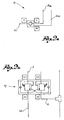
- . - figure 1 shows a three-dimensional, schematic view of a hydraulic circuit
- - figures 2a and 2b represent a diagram of a lock valve and a main lock valve of the hydraulic circuit in figure 1, and
- FIG. 1 represents a detailed diagram of a hydraulic system comprising the circuit in figure 1.
- a hydraulic circuit is globally indicated with reference numeral 1, according to the present invention, according to a preferred embodiment.
- Said circuit comprises at least one actuator 2 for lifting a bed and/or footboard.
- Said actuator is preferably a single action type actuator, in other words it is suitable to influence the bed only for lifting, whereas the lowering of said bed is achieved by gravity.
- said actuator is a double action type actuator, in other words it is suitable to influence the footboard so it can be both lifted and lowered.
- the hydraulic circuit 1 comprises a main line 4 that is operatively connected to said actuators.
- Said main line 4 is preferably connected in parallel to said actuators 2.
- said main line 4 comprises branching out stretches 4a, which branch out from said main line 4.
- said hydraulic circuit 1 comprises a pilot line 6, which is operatively connected to said actuators 2 suitable to transmit a pilot signal in the form of work fluid pressure.
- said pilot line 6 is connected in parallel to said actuators 2.
- said pilot line 6 comprises branching out stretches 6a, which branch out from said pilot line 6.
- the hydraulic circuit 1 also comprises at least one lock valve 8. Said circuit preferably comprises a lock valve 8 for each actuator 2.
- Said lock valve is, for example, a three-way valve, in particular with two inputs and one output.
- said lock valve 8 is connected in input to a branching out stretch 4a of the main line 4 of the circuit, to a branching out stretch 6a of the pilot line 6, and, in output, to a connecting strip 10 to the respective actuator 2.
- the lock valve 8 is realised so that it constitutes a unidirectional valve, sometimes called a "no return" valve, from the main line 4 to the connecting strip 10 to the actuator 2.
- the lock valve 8 can be crossed by the work fluid from the main line 4 to the connecting strip 10, feeding the actuator. In these conditions, on the contrary, the lock valve cannot be crossed by the work fluid from the connecting strip 10 to the main line 4, preventing the actuator from withdrawing.
- the lock valve 8 When there is a pilot signal along the pilot line 6, the lock valve 8 is piloted on opening, in other words it allows the work fluid to pass from the connecting strip 10 to the main line 4.
- said lock valve is gauged at a first level of pressure, for example between 25 and 45 bars inclusive, preferably between 30 and 40 bars.
- said hydraulic circuit preferably comprises a pressure switch.
- said hydraulic circuit preferably comprises a pressure test connector. Said pressure switch and/or said pressure test connector are preferably operatively connected to said pilot line 6, upstream of said branching out stretches 6a.
- the hydraulic circuit 1 comprises a main lock valve 12 and a distributor 16 upstream of said main lock valve.
- Said main lock valve 12 is preferably a four-way valve with two inputs and two outputs.
- a first output is drained.
- a second output is connected to the main line 4.
- a first input is connected to the pilot line 6.
- a second input is connected to a connecting strip 14 with the distributor 16.
- Said main lock valve 12 comprises two normally closed two-way valves, in other words to prevent the work fluid from passing unless a preset command signal is given.
- said two-way valves are gauged at a second level of pressure, which is generally much higher than the first level of pressure at which the lock valves 8 are gauged.
- Said second level of pressure is preferably equal to three or four times the first level of pressure.
- the first two-way valve is connected to the connecting strip 14 and to the main line 4.
- the second two-way valve is connected to the pilot line 6 and is drained.
- the first two-way valve is influenced on opening by the pilot signal and by the work fluid in the main line 4.
- the second two-way valve is influenced on opening by the level of pressure of the connecting strip 14.
- the distributor 16 is connected in input to a power line 18 that is connected to a device for putting the fluid under pressure, for example an electro-pump, which is also drained.
- pilot line 6 pilots the lock valves 8, so that said valves can be crossed by the work fluid from the connecting strip 10 to the branching out stretch 4a of the main line 4.
- the actuators are authorised to lower, although this does not take place until the first two-way valve of the main lock valve 12 is open.
- the first two-way valve of the main lock valve 12 is influenced on opening by the level of pressure in the main line 4.
- the second level of pressure is much higher than the first level of pressure that makes the lock vales 8 open, so the main lock valve 12 only opens when the second level of pressure is reached in the main line by means of the load weighing on the bed.
- the hydraulic circuit allows correct lowering of the bed or floorboard that are influenced by the actuators.
- the circuit foresees a first valve to authorise the lowering and a second open valve, which effectively permits the lowering.
- This second valve is brought into an open position only when there is a determined load weighing on the bed.
- This circuit is particularly suitable for use with commercial vehicles, trailers, semi-trailers and lorries, which often present a considerable difference in the conditions of the load weighing on each actuator, as they have large beds for lifting or lowering.
- the above-described circuit allows the bed or footboard to be held at a determined height, even when there is a leakage of work fluid.
- the above-described circuit allows the authorisation to lower the actuators, which is piloted by the pilot signal of the pilot line, and the actual lowering, which is commanded by the load conditions weighing on the bed or footboard.
- the lowering takes place when it is commanded and authorised. If there is also authorisation for all of the lock valves, but not a lowering command, in other words the main lock valve stays closed, the lowering does not take place.
- a bed or footboard for example, act in conjunction with a number of actuators for their lifting and/or lowering, and said hydraulic circuit presents a number of lock valves inferior to the number of actuators.
- not all of the actuators are fitted with a lock valve.
Landscapes
- Engineering & Computer Science (AREA)
- Transportation (AREA)
- Mechanical Engineering (AREA)
- Health & Medical Sciences (AREA)
- Public Health (AREA)
- Fluid-Pressure Circuits (AREA)
- Forklifts And Lifting Vehicles (AREA)
Abstract
Description
- . The present invention relates to a hydraulic circuit, in particular an oleodynamic one, which is particularly suitable to be used to lift and lower beds and/or footboards, for example in vehicles for transporting goods, such as lorries, trailers and semi-trailers.
- . The use of hydraulic circuits is known, comprising hydraulic actuators for lifting beds and/or footboards. Said actuators are generally single action actuators, in other words, they are suitable to influence the bed so that it can be lifted, whereas the lowering of the bed is guaranteed by gravity acting on the drained actuators.
- . In these types of systems, lock valves, in other words unidirectional valves, are foreseen to ensure that the lifted bed is kept at the required height. These valves allow work fluid to pass to the actuator to lift the bed, however they stop the fluid from passing in the opposite direction to prevent the bed from lowering.
- . Whereas when the bed needs to be lowered, the lock valves are commanded to allow the passage of the fluid to come out of the cylinder.
- . However these circuits present some disadvantages.
- . Firstly they do not guarantee correct lowering of the bed, which is basically due to the different load conditions weighing on each actuator. These load conditions influence the ways in which the actuator withdraws, starting with the speed.
- . This disadvantage is particularly felt in the sector of constructing trailers, semi-trailers, lorries and the like, for transporting goods.
- . In fact in this sector the aforesaid circuits act in conjunction with footboards or beds of a considerable size, and their load conditions weighing on each actuator can also be very different; this results in unwanted inclination of the bed or footboard and sometimes their breaking.
- . It is the object of the present invention to realise a hydraulic circuit, which is particularly suitable to act in conjunction with a bed and/or footboard, in particular of a trailer, semi-trailer and the like, for their correct lifting and/or lowering.
- . Such object is achieved with a hydraulic circuit realised in keeping with the following claim 1. The claims depending on this describe executable variations.
- . The characteristics and advantages of the circuit according to the present invention will be appreciated from the description reported below of an embodiment, given by way of example, which is not limiting, in keeping with the accompanying figures, wherein:
- . - figure 1 shows a three-dimensional, schematic view of a hydraulic circuit;
- . - figures 2a and 2b represent a diagram of a lock valve and a main lock valve of the hydraulic circuit in figure 1, and
- . - figure 3 represents a detailed diagram of a hydraulic system comprising the circuit in figure 1.
- . With reference to the accompanying figures, a hydraulic circuit is globally indicated with reference numeral 1, according to the present invention, according to a preferred embodiment.
- . Said circuit comprises at least one
actuator 2 for lifting a bed and/or footboard. Said actuator is preferably a single action type actuator, in other words it is suitable to influence the bed only for lifting, whereas the lowering of said bed is achieved by gravity. - . According to a variation of embodiment, said actuator is a double action type actuator, in other words it is suitable to influence the footboard so it can be both lifted and lowered.
- . The hydraulic circuit 1 comprises a
main line 4 that is operatively connected to said actuators. - . Said
main line 4 is preferably connected in parallel to saidactuators 2. In other words, saidmain line 4 comprises branching outstretches 4a, which branch out from saidmain line 4. - . Moreover, said hydraulic circuit 1 comprises a pilot line 6, which is operatively connected to said
actuators 2 suitable to transmit a pilot signal in the form of work fluid pressure. - . According to a preferred embodiment, said pilot line 6 is connected in parallel to said
actuators 2. In other words, said pilot line 6 comprises branching outstretches 6a, which branch out from said pilot line 6. - . The hydraulic circuit 1 also comprises at least one
lock valve 8. Said circuit preferably comprises alock valve 8 for eachactuator 2. - . Said lock valve is, for example, a three-way valve, in particular with two inputs and one output. In particular, said
lock valve 8 is connected in input to a branching outstretch 4a of themain line 4 of the circuit, to a branching outstretch 6a of the pilot line 6, and, in output, to a connectingstrip 10 to therespective actuator 2. - . The
lock valve 8 is realised so that it constitutes a unidirectional valve, sometimes called a "no return" valve, from themain line 4 to the connectingstrip 10 to theactuator 2. - . In other words, when there is no pilot signal along the pilot line 6, in other words when said pilot line is drained, the
lock valve 8 can be crossed by the work fluid from themain line 4 to the connectingstrip 10, feeding the actuator. In these conditions, on the contrary, the lock valve cannot be crossed by the work fluid from the connectingstrip 10 to themain line 4, preventing the actuator from withdrawing. - . When there is a pilot signal along the pilot line 6, the
lock valve 8 is piloted on opening, in other words it allows the work fluid to pass from the connectingstrip 10 to themain line 4. - . According to a preferred embodiment, said lock valve is gauged at a first level of pressure, for example between 25 and 45 bars inclusive, preferably between 30 and 40 bars.
- . In other words, when the fluid pressure in the pilot line 6 reaches said first level of pressure, the lock valve is open, as described above.
- . Moreover, said hydraulic circuit preferably comprises a pressure switch. Moreover, said hydraulic circuit preferably comprises a pressure test connector. Said pressure switch and/or said pressure test connector are preferably operatively connected to said pilot line 6, upstream of said branching out
stretches 6a. - . Moreover, the hydraulic circuit 1 comprises a
main lock valve 12 and adistributor 16 upstream of said main lock valve. - . Said
main lock valve 12 is preferably a four-way valve with two inputs and two outputs. - . A first output is drained. A second output is connected to the
main line 4. - . A first input is connected to the pilot line 6. A second input is connected to a connecting
strip 14 with thedistributor 16. - . Said
main lock valve 12 comprises two normally closed two-way valves, in other words to prevent the work fluid from passing unless a preset command signal is given. - . In particular, said two-way valves are gauged at a second level of pressure, which is generally much higher than the first level of pressure at which the
lock valves 8 are gauged. - . Said second level of pressure is preferably equal to three or four times the first level of pressure.
- . The first two-way valve is connected to the connecting
strip 14 and to themain line 4. The second two-way valve is connected to the pilot line 6 and is drained. - . The first two-way valve is influenced on opening by the pilot signal and by the work fluid in the
main line 4. The second two-way valve is influenced on opening by the level of pressure of the connectingstrip 14. - . The
distributor 16 is connected in input to apower line 18 that is connected to a device for putting the fluid under pressure, for example an electro-pump, which is also drained. - . In a first position of the distributor, said neutral position, the pilot line 6 is drained. Consequently the
lock valves 8 do not receive any pilot signal and stop the actuator from withdrawing. - . In other words, in said conditions, the lifted bed or footboard stay at the required height.
- . This raised position is also maintained in the event of work fluid leaking upstream of the
lock valves 8. - . In a second position of the
distributor 16, said lifting position, thepower line 18 upstream of the distributor is connected to the connectingstrip 14 downstream of this. - . The work fluid in the connecting
strip 14, put under pressure by the electro-pump, influences the first two-way valve of themain lock valve 12, bringing said first two-way valve from the normally closed position to the open position, in which the connectingstrip 14 is joined to themain line 4. - . In said state, the actuators are fed with work fluid and the bed or footboard is lifted.
- . In a third position of the
distributor 16, said lowering position, the pilot line 6 is put under pressure. - . On opening, said pilot line 6 pilots the
lock valves 8, so that said valves can be crossed by the work fluid from the connectingstrip 10 to the branching outstretch 4a of themain line 4. - . In other words, the actuators are authorised to lower, although this does not take place until the first two-way valve of the
main lock valve 12 is open. - . The first two-way valve of the
main lock valve 12 is influenced on opening by the level of pressure in themain line 4. - . The second level of pressure is much higher than the first level of pressure that makes the
lock vales 8 open, so themain lock valve 12 only opens when the second level of pressure is reached in the main line by means of the load weighing on the bed. - . This guarantees simultaneous lowering of the actuators.
- . Innovatively, according to the present invention the hydraulic circuit allows correct lowering of the bed or floorboard that are influenced by the actuators.
- . Advantageously, the circuit foresees a first valve to authorise the lowering and a second open valve, which effectively permits the lowering. This second valve is brought into an open position only when there is a determined load weighing on the bed.
- . This circuit is particularly suitable for use with commercial vehicles, trailers, semi-trailers and lorries, which often present a considerable difference in the conditions of the load weighing on each actuator, as they have large beds for lifting or lowering.
- . Also advantageously the above-described circuit allows the bed or footboard to be held at a determined height, even when there is a leakage of work fluid.
- . Advantageously, note that the above-described circuit allows the authorisation to lower the actuators, which is piloted by the pilot signal of the pilot line, and the actual lowering, which is commanded by the load conditions weighing on the bed or footboard.
- . In other words, the lowering takes place when it is commanded and authorised. If there is also authorisation for all of the lock valves, but not a lowering command, in other words the main lock valve stays closed, the lowering does not take place.
- . Clearly those skilled in the art can make modifications and variations to the above described circuit to satisfy specific, contingent needs.
- . In a variation of embodiment, a bed or footboard, for example, act in conjunction with a number of actuators for their lifting and/or lowering, and said hydraulic circuit presents a number of lock valves inferior to the number of actuators.
- . In other words, in a variation of embodiment, not all of the actuators are fitted with a lock valve.
- . These variations are also to be included in the scope of protection defined by the following claims.
Claims (14)
- Hydraulic circuit (1) suitable to act in conjunction with a bed and/or footboard to be lifted and/or lowered, said circuit being joinable to a device for putting a work fluid under pressure, wherein said circuit comprises:- at least one actuator (2) that is operatively connected to said bed or said footboard;- a main line (4) for feeding the work fluid to said actuator (2);- a pilot line (6) separate from said main line (4), which is suitable to transmit a pilot signal;- at least one lock valve (8) set upstream of each actuator (2) that is operatively connected to said main line and to said pilot line, said valve being unidirectional towards the actuator and pilotable on opening in the opposite direction and being gauged on opening at a first level of pressure of the pilot line (6) ;- a distributor (16) that is operatively connected to said main line (4) and to said pilot line (6) and joinable to said device for putting the fluid under pressure;said system being characterised in that it also comprises a main lock valve (12) upstream of said lock valves (8) and downstream of said distributor, which is operatively connected to said distributor (16), to said pilot line and to said main line, said main valve (12) being gauged on opening at a second level of pressure of the main line (4), which is greater than the first level of pressure, in said open position the reflux of the work fluid being allowed by the main line.
- Circuit according to claim 1, wherein said actuator (2) is a single action actuator.
- Circuit according to claim 1, wherein said actuator (2) is a double action actuator.
- Circuit according to any one of the previous claims,
wherein said main lock valve (12) is a four-way valve. - Circuit according to any one of the previous claims,
wherein said lock valve (8) is a three-way valve. - Circuit according to any one of the previous claims,
wherein said distributor (16) presents a neutral position, in which said pilot line (6) is drained. - Circuit according to any one of the previous claims,
wherein said distributor (16) presents a lifting position in which said device for putting the fluid under pressure is operatively connected to said main line (4). - Circuit according to any one of the previous claims,
wherein said distributor presents a lowering position, in which said pilot line (6) is under pressure. - Hydraulic system comprising a circuit (1) realised in keeping with any one of the previous claims, comprising said device for putting the fluid under pressure.
- System according to claim 9, wherein said device for putting the fluid under pressure is an electro-pump.
- Trailer, semi-trailer or vehicle for transporting goods comprising a bed or a footboard to be lifted and/or lowered, and a circuit realised in keeping with any one of the previous claims from 1 to 8.
- Trailer, semi-trailer or vehicle according to claim 11 comprising additional actuators, which do not act in conjunction with lock valves (8).
- Hydraulic circuit (1) suitable to act in conjunction with a bed and/or footboard to be lifted and/or lowered,
wherein said circuit comprises:- at least one actuator (2) that is operatively connected to said bed or said footboard;- a main line (4) for feeding the work fluid to said actuator (2);- a pilot line (6), separate from said main line (4), that is suitable to transmit a pilot signal;- at least one lock valve (8) set upstream of each actuator (2), which is operatively connected to said main line, said valve being unidirectional towards the actuator and pilotable on opening in the opposite direction by the pilot signal;said circuit being characterised in that it also comprises a main lock valve (12), which is operatively connected to said main line (4), said main lock valve (12) being pilotable on opening by the load conditions weighing on the bed to allow the reflux of the work fluid from the main line. - Hydraulic circuit (1) suitable to act in conjunction with a bed and/or a footboard for lifting and/or lowering, wherein said circuit comprises:- at least one actuator (2) that is operatively connected to said bed or said footboard;- a main line (4) to feed the work fluid to said actuator (2);- a pilot line (6), separate from said main line (4), suitable to transmit a pilot signal;- at least one lock valve (8) set upstream of each actuator (2) that is operatively connected to said main line;- a main lock valve (12), upstream of the lock valves (8) that is operatively connected to said main line (4);wherein, to lower the bed, said pilot signal authorises the lock valves(8) and the load weighing on the bed opens said main lock valve (12) for the reflux of the work fluid from the main line (4).
Applications Claiming Priority (1)
| Application Number | Priority Date | Filing Date | Title |
|---|---|---|---|
| IT2004000559 | 2004-10-08 |
Publications (2)
| Publication Number | Publication Date |
|---|---|
| EP1645463A1 true EP1645463A1 (en) | 2006-04-12 |
| EP1645463B1 EP1645463B1 (en) | 2007-12-19 |
Family
ID=35033522
Family Applications (1)
| Application Number | Title | Priority Date | Filing Date |
|---|---|---|---|
| EP04425797A Expired - Lifetime EP1645463B1 (en) | 2004-10-08 | 2004-10-25 | Hydraulic circuit for lifting and lowering beds and/or footboards of a trailer, semi-trailer and the like |
Country Status (3)
| Country | Link |
|---|---|
| EP (1) | EP1645463B1 (en) |
| AT (1) | ATE381463T1 (en) |
| DE (1) | DE602004010813D1 (en) |
Cited By (1)
| Publication number | Priority date | Publication date | Assignee | Title |
|---|---|---|---|---|
| GB2554335A (en) * | 2016-05-20 | 2018-04-04 | Parkhouse Country Estates Ltd | Improvements in and relating to vehicles |
Citations (3)
| Publication number | Priority date | Publication date | Assignee | Title |
|---|---|---|---|---|
| US5110251A (en) * | 1989-01-17 | 1992-05-05 | Gray Ralph E | Hydraulic platform lift for truck trailers |
| US5791860A (en) * | 1997-01-27 | 1998-08-11 | Holland Equipment Limited | Hydraulic platform lift for a truck tailgate |
| DE19960302A1 (en) * | 1999-12-14 | 2001-06-21 | Meiller Fahrzeuge | Control valve device for hydraulic cylinder, which in blocking bypass state can act as pressure limiting valve acting towards container |
-
2004
- 2004-10-25 AT AT04425797T patent/ATE381463T1/en not_active IP Right Cessation
- 2004-10-25 DE DE602004010813T patent/DE602004010813D1/en not_active Expired - Lifetime
- 2004-10-25 EP EP04425797A patent/EP1645463B1/en not_active Expired - Lifetime
Patent Citations (3)
| Publication number | Priority date | Publication date | Assignee | Title |
|---|---|---|---|---|
| US5110251A (en) * | 1989-01-17 | 1992-05-05 | Gray Ralph E | Hydraulic platform lift for truck trailers |
| US5791860A (en) * | 1997-01-27 | 1998-08-11 | Holland Equipment Limited | Hydraulic platform lift for a truck tailgate |
| DE19960302A1 (en) * | 1999-12-14 | 2001-06-21 | Meiller Fahrzeuge | Control valve device for hydraulic cylinder, which in blocking bypass state can act as pressure limiting valve acting towards container |
Cited By (2)
| Publication number | Priority date | Publication date | Assignee | Title |
|---|---|---|---|---|
| GB2554335A (en) * | 2016-05-20 | 2018-04-04 | Parkhouse Country Estates Ltd | Improvements in and relating to vehicles |
| GB2554335B (en) * | 2016-05-20 | 2019-10-09 | Parkhouse Country Estates Ltd | A hydraulic vehicular roof assembly |
Also Published As
| Publication number | Publication date |
|---|---|
| ATE381463T1 (en) | 2008-01-15 |
| DE602004010813D1 (en) | 2008-01-31 |
| EP1645463B1 (en) | 2007-12-19 |
Similar Documents
| Publication | Publication Date | Title |
|---|---|---|
| DE10333610B4 (en) | Compressed air treatment device for motor vehicle compressed air systems | |
| EP1369598B1 (en) | Electro-hydraulic lifting control device for industrial use vehicles | |
| EP2384943B1 (en) | Valve device, electrically actuated handbrake and method for controlling same | |
| EP2547565B1 (en) | Electrically actuatable parking brake system | |
| EP2024214B1 (en) | Method for controlling or regulating the air pressure in a compressed air supply device | |
| DE102016106793B4 (en) | Hydraulic steering | |
| DE102011051505B4 (en) | Level control valve unit with integrated distributor | |
| EP1820708A2 (en) | Hydraulic assembly | |
| EP2338753A1 (en) | Electrically actuated handbrake and method for controlling the same | |
| EP2516186B1 (en) | Valve device for an air suspension system | |
| EP2540538B1 (en) | Pneumatic spring assembly | |
| DE102015115082B4 (en) | Valve unit for pneumatic applications as well as air suspension system | |
| DE102009005229B4 (en) | Air spring system with height limitation | |
| EP1645463B1 (en) | Hydraulic circuit for lifting and lowering beds and/or footboards of a trailer, semi-trailer and the like | |
| DE2533673C2 (en) | Hydraulic control system | |
| EP2338754B1 (en) | Electrically actuated handbrake and method for controlling same | |
| DE102015226432A1 (en) | Brake valve assembly and method for a brake valve assembly | |
| EP2466154B1 (en) | Electrohydraulic control device | |
| EP2016818A1 (en) | Hoisting gear and method for operating such a hoisting gear | |
| EP3436705B1 (en) | Control device | |
| EP2016817B1 (en) | Method for operating a hoisting gear and hoisting gear | |
| US7152401B2 (en) | Hydraulic steering arrangement | |
| JPH075272B2 (en) | Side shift clamp device | |
| EP3037678B1 (en) | Lifting module | |
| EP2384944B1 (en) | Method for operating an electrically actuated handbrake |
Legal Events
| Date | Code | Title | Description |
|---|---|---|---|
| PUAI | Public reference made under article 153(3) epc to a published international application that has entered the european phase |
Free format text: ORIGINAL CODE: 0009012 |
|
| AK | Designated contracting states |
Kind code of ref document: A1 Designated state(s): AT BE BG CH CY CZ DE DK EE ES FI FR GB GR HU IE IT LI LU MC NL PL PT RO SE SI SK TR |
|
| AX | Request for extension of the european patent |
Extension state: AL HR LT LV MK |
|
| 17P | Request for examination filed |
Effective date: 20060613 |
|
| 17Q | First examination report despatched |
Effective date: 20060720 |
|
| AKX | Designation fees paid |
Designated state(s): AT BE BG CH CY CZ DE DK EE ES FI FR GB GR HU IE IT LI LU MC NL PL PT RO SE SI SK TR |
|
| GRAP | Despatch of communication of intention to grant a patent |
Free format text: ORIGINAL CODE: EPIDOSNIGR1 |
|
| GRAS | Grant fee paid |
Free format text: ORIGINAL CODE: EPIDOSNIGR3 |
|
| GRAA | (expected) grant |
Free format text: ORIGINAL CODE: 0009210 |
|
| AK | Designated contracting states |
Kind code of ref document: B1 Designated state(s): AT BE BG CH CY CZ DE DK EE ES FI FR GB GR HU IE IT LI LU MC NL PL PT RO SE SI SK TR |
|
| REG | Reference to a national code |
Ref country code: GB Ref legal event code: FG4D |
|
| REG | Reference to a national code |
Ref country code: IE Ref legal event code: FG4D |
|
| REG | Reference to a national code |
Ref country code: CH Ref legal event code: EP |
|
| REF | Corresponds to: |
Ref document number: 602004010813 Country of ref document: DE Date of ref document: 20080131 Kind code of ref document: P |
|
| PG25 | Lapsed in a contracting state [announced via postgrant information from national office to epo] |
Ref country code: LI Free format text: LAPSE BECAUSE OF FAILURE TO SUBMIT A TRANSLATION OF THE DESCRIPTION OR TO PAY THE FEE WITHIN THE PRESCRIBED TIME-LIMIT Effective date: 20071219 Ref country code: CH Free format text: LAPSE BECAUSE OF FAILURE TO SUBMIT A TRANSLATION OF THE DESCRIPTION OR TO PAY THE FEE WITHIN THE PRESCRIBED TIME-LIMIT Effective date: 20071219 Ref country code: SE Free format text: LAPSE BECAUSE OF FAILURE TO SUBMIT A TRANSLATION OF THE DESCRIPTION OR TO PAY THE FEE WITHIN THE PRESCRIBED TIME-LIMIT Effective date: 20080319 |
|
| PG25 | Lapsed in a contracting state [announced via postgrant information from national office to epo] |
Ref country code: SI Free format text: LAPSE BECAUSE OF FAILURE TO SUBMIT A TRANSLATION OF THE DESCRIPTION OR TO PAY THE FEE WITHIN THE PRESCRIBED TIME-LIMIT Effective date: 20071219 Ref country code: PL Free format text: LAPSE BECAUSE OF FAILURE TO SUBMIT A TRANSLATION OF THE DESCRIPTION OR TO PAY THE FEE WITHIN THE PRESCRIBED TIME-LIMIT Effective date: 20071219 Ref country code: NL Free format text: LAPSE BECAUSE OF FAILURE TO SUBMIT A TRANSLATION OF THE DESCRIPTION OR TO PAY THE FEE WITHIN THE PRESCRIBED TIME-LIMIT Effective date: 20071219 Ref country code: FI Free format text: LAPSE BECAUSE OF FAILURE TO SUBMIT A TRANSLATION OF THE DESCRIPTION OR TO PAY THE FEE WITHIN THE PRESCRIBED TIME-LIMIT Effective date: 20071219 |
|
| NLV1 | Nl: lapsed or annulled due to failure to fulfill the requirements of art. 29p and 29m of the patents act | ||
| REG | Reference to a national code |
Ref country code: CH Ref legal event code: PL |
|
| PG25 | Lapsed in a contracting state [announced via postgrant information from national office to epo] |
Ref country code: AT Free format text: LAPSE BECAUSE OF FAILURE TO SUBMIT A TRANSLATION OF THE DESCRIPTION OR TO PAY THE FEE WITHIN THE PRESCRIBED TIME-LIMIT Effective date: 20071219 |
|
| PG25 | Lapsed in a contracting state [announced via postgrant information from national office to epo] |
Ref country code: ES Free format text: LAPSE BECAUSE OF FAILURE TO SUBMIT A TRANSLATION OF THE DESCRIPTION OR TO PAY THE FEE WITHIN THE PRESCRIBED TIME-LIMIT Effective date: 20080330 Ref country code: CZ Free format text: LAPSE BECAUSE OF FAILURE TO SUBMIT A TRANSLATION OF THE DESCRIPTION OR TO PAY THE FEE WITHIN THE PRESCRIBED TIME-LIMIT Effective date: 20071219 |
|
| PG25 | Lapsed in a contracting state [announced via postgrant information from national office to epo] |
Ref country code: BE Free format text: LAPSE BECAUSE OF FAILURE TO SUBMIT A TRANSLATION OF THE DESCRIPTION OR TO PAY THE FEE WITHIN THE PRESCRIBED TIME-LIMIT Effective date: 20071219 Ref country code: SK Free format text: LAPSE BECAUSE OF FAILURE TO SUBMIT A TRANSLATION OF THE DESCRIPTION OR TO PAY THE FEE WITHIN THE PRESCRIBED TIME-LIMIT Effective date: 20071219 Ref country code: RO Free format text: LAPSE BECAUSE OF FAILURE TO SUBMIT A TRANSLATION OF THE DESCRIPTION OR TO PAY THE FEE WITHIN THE PRESCRIBED TIME-LIMIT Effective date: 20071219 |
|
| PG25 | Lapsed in a contracting state [announced via postgrant information from national office to epo] |
Ref country code: PT Free format text: LAPSE BECAUSE OF FAILURE TO SUBMIT A TRANSLATION OF THE DESCRIPTION OR TO PAY THE FEE WITHIN THE PRESCRIBED TIME-LIMIT Effective date: 20080519 |
|
| EN | Fr: translation not filed | ||
| PLBE | No opposition filed within time limit |
Free format text: ORIGINAL CODE: 0009261 |
|
| STAA | Information on the status of an ep patent application or granted ep patent |
Free format text: STATUS: NO OPPOSITION FILED WITHIN TIME LIMIT |
|
| PG25 | Lapsed in a contracting state [announced via postgrant information from national office to epo] |
Ref country code: DK Free format text: LAPSE BECAUSE OF FAILURE TO SUBMIT A TRANSLATION OF THE DESCRIPTION OR TO PAY THE FEE WITHIN THE PRESCRIBED TIME-LIMIT Effective date: 20071219 Ref country code: DE Free format text: LAPSE BECAUSE OF FAILURE TO SUBMIT A TRANSLATION OF THE DESCRIPTION OR TO PAY THE FEE WITHIN THE PRESCRIBED TIME-LIMIT Effective date: 20080320 |
|
| 26N | No opposition filed |
Effective date: 20080922 |
|
| PGFP | Annual fee paid to national office [announced via postgrant information from national office to epo] |
Ref country code: IT Payment date: 20080724 Year of fee payment: 5 |
|
| PG25 | Lapsed in a contracting state [announced via postgrant information from national office to epo] |
Ref country code: GR Free format text: LAPSE BECAUSE OF FAILURE TO SUBMIT A TRANSLATION OF THE DESCRIPTION OR TO PAY THE FEE WITHIN THE PRESCRIBED TIME-LIMIT Effective date: 20080320 |
|
| PG25 | Lapsed in a contracting state [announced via postgrant information from national office to epo] |
Ref country code: FR Free format text: LAPSE BECAUSE OF FAILURE TO SUBMIT A TRANSLATION OF THE DESCRIPTION OR TO PAY THE FEE WITHIN THE PRESCRIBED TIME-LIMIT Effective date: 20081010 Ref country code: BG Free format text: LAPSE BECAUSE OF FAILURE TO SUBMIT A TRANSLATION OF THE DESCRIPTION OR TO PAY THE FEE WITHIN THE PRESCRIBED TIME-LIMIT Effective date: 20080319 Ref country code: EE Free format text: LAPSE BECAUSE OF FAILURE TO SUBMIT A TRANSLATION OF THE DESCRIPTION OR TO PAY THE FEE WITHIN THE PRESCRIBED TIME-LIMIT Effective date: 20071219 |
|
| PG25 | Lapsed in a contracting state [announced via postgrant information from national office to epo] |
Ref country code: MC Free format text: LAPSE BECAUSE OF NON-PAYMENT OF DUE FEES Effective date: 20081031 |
|
| GBPC | Gb: european patent ceased through non-payment of renewal fee |
Effective date: 20081025 |
|
| PG25 | Lapsed in a contracting state [announced via postgrant information from national office to epo] |
Ref country code: CY Free format text: LAPSE BECAUSE OF FAILURE TO SUBMIT A TRANSLATION OF THE DESCRIPTION OR TO PAY THE FEE WITHIN THE PRESCRIBED TIME-LIMIT Effective date: 20071219 |
|
| PG25 | Lapsed in a contracting state [announced via postgrant information from national office to epo] |
Ref country code: IE Free format text: LAPSE BECAUSE OF NON-PAYMENT OF DUE FEES Effective date: 20081027 |
|
| PG25 | Lapsed in a contracting state [announced via postgrant information from national office to epo] |
Ref country code: GB Free format text: LAPSE BECAUSE OF NON-PAYMENT OF DUE FEES Effective date: 20081025 |
|
| PG25 | Lapsed in a contracting state [announced via postgrant information from national office to epo] |
Ref country code: LU Free format text: LAPSE BECAUSE OF NON-PAYMENT OF DUE FEES Effective date: 20081025 Ref country code: HU Free format text: LAPSE BECAUSE OF FAILURE TO SUBMIT A TRANSLATION OF THE DESCRIPTION OR TO PAY THE FEE WITHIN THE PRESCRIBED TIME-LIMIT Effective date: 20080620 |
|
| PG25 | Lapsed in a contracting state [announced via postgrant information from national office to epo] |
Ref country code: TR Free format text: LAPSE BECAUSE OF FAILURE TO SUBMIT A TRANSLATION OF THE DESCRIPTION OR TO PAY THE FEE WITHIN THE PRESCRIBED TIME-LIMIT Effective date: 20071219 |
|
| PG25 | Lapsed in a contracting state [announced via postgrant information from national office to epo] |
Ref country code: IT Free format text: LAPSE BECAUSE OF NON-PAYMENT OF DUE FEES Effective date: 20091025 |