EP1820708A2 - Hydraulic assembly - Google Patents
Hydraulic assembly Download PDFInfo
- Publication number
- EP1820708A2 EP1820708A2 EP07102574A EP07102574A EP1820708A2 EP 1820708 A2 EP1820708 A2 EP 1820708A2 EP 07102574 A EP07102574 A EP 07102574A EP 07102574 A EP07102574 A EP 07102574A EP 1820708 A2 EP1820708 A2 EP 1820708A2
- Authority
- EP
- European Patent Office
- Prior art keywords
- pressure
- trailer
- hydraulic
- brake
- line
- Prior art date
- Legal status (The legal status is an assumption and is not a legal conclusion. Google has not performed a legal analysis and makes no representation as to the accuracy of the status listed.)
- Granted
Links
- 238000010586 diagram Methods 0.000 description 11
- 239000012530 fluid Substances 0.000 description 7
- 230000008901 benefit Effects 0.000 description 4
- 230000008859 change Effects 0.000 description 4
- 230000001276 controlling effect Effects 0.000 description 4
- 230000036316 preload Effects 0.000 description 4
- 230000007423 decrease Effects 0.000 description 3
- 230000009467 reduction Effects 0.000 description 3
- 230000004044 response Effects 0.000 description 3
- 230000033228 biological regulation Effects 0.000 description 2
- 230000008878 coupling Effects 0.000 description 2
- 238000010168 coupling process Methods 0.000 description 2
- 238000005859 coupling reaction Methods 0.000 description 2
- 238000012986 modification Methods 0.000 description 2
- 230000004048 modification Effects 0.000 description 2
- 230000003247 decreasing effect Effects 0.000 description 1
- 230000001419 dependent effect Effects 0.000 description 1
- 238000011161 development Methods 0.000 description 1
- 230000018109 developmental process Effects 0.000 description 1
- 230000000694 effects Effects 0.000 description 1
- 238000005457 optimization Methods 0.000 description 1
- 230000001105 regulatory effect Effects 0.000 description 1
- 230000003014 reinforcing effect Effects 0.000 description 1
Images


Classifications
-
- B—PERFORMING OPERATIONS; TRANSPORTING
- B60—VEHICLES IN GENERAL
- B60T—VEHICLE BRAKE CONTROL SYSTEMS OR PARTS THEREOF; BRAKE CONTROL SYSTEMS OR PARTS THEREOF, IN GENERAL; ARRANGEMENT OF BRAKING ELEMENTS ON VEHICLES IN GENERAL; PORTABLE DEVICES FOR PREVENTING UNWANTED MOVEMENT OF VEHICLES; VEHICLE MODIFICATIONS TO FACILITATE COOLING OF BRAKES
- B60T7/00—Brake-action initiating means
- B60T7/12—Brake-action initiating means for automatic initiation; for initiation not subject to will of driver or passenger
- B60T7/20—Brake-action initiating means for automatic initiation; for initiation not subject to will of driver or passenger specially for trailers, e.g. in case of uncoupling of or overrunning by trailer
-
- B—PERFORMING OPERATIONS; TRANSPORTING
- B60—VEHICLES IN GENERAL
- B60T—VEHICLE BRAKE CONTROL SYSTEMS OR PARTS THEREOF; BRAKE CONTROL SYSTEMS OR PARTS THEREOF, IN GENERAL; ARRANGEMENT OF BRAKING ELEMENTS ON VEHICLES IN GENERAL; PORTABLE DEVICES FOR PREVENTING UNWANTED MOVEMENT OF VEHICLES; VEHICLE MODIFICATIONS TO FACILITATE COOLING OF BRAKES
- B60T11/00—Transmitting braking action from initiating means to ultimate brake actuator without power assistance or drive or where such assistance or drive is irrelevant
- B60T11/10—Transmitting braking action from initiating means to ultimate brake actuator without power assistance or drive or where such assistance or drive is irrelevant transmitting by fluid means, e.g. hydraulic
- B60T11/108—Transmitting braking action from initiating means to ultimate brake actuator without power assistance or drive or where such assistance or drive is irrelevant transmitting by fluid means, e.g. hydraulic to a trailer fluid system
Definitions
- the invention relates to a hydraulic arrangement for braking a trailer, with a hydraulically connectable to a brake system of a trailer brake line, a hydraulic source, a hydraulic tank, a hydraulic source and the tank with the brake line connecting, hydraulically controllable trailer brake valve, a between the brake line and the Trailer brake valve extending first control pressure line, a extending between the trailer brake valve and a control pressure source second control pressure line and arranged in the second control pressure line, adjustable, pressure reducing means for controlling the control pressure.
- the object underlying the invention is seen to provide a hydraulic arrangement of the type mentioned, by which the aforementioned problems are overcome.
- a hydraulic arrangement of the aforementioned type comprises a control pressure source, which is formed as part of the hydraulic circuit of a brake system of a towing vehicle pulling the trailer, wherein the pressure reducing means by an adjustable biasing force mechanically in an open basic position is zwingbar.
- the control pressure source is formed as part of the hydraulic circuit of the brake system of the towing vehicle
- a control pressure in the second control pressure line can be generated by generating a brake pressure in the towing vehicle, for example by pressing the brake pedal.
- the pressure reducing means is in an open basic position, so that even if an electronic control fails on the towing vehicle, the functionality of the hydraulic brake system for the trailer is guaranteed.
- the control pressure source can be designed, for example, as a hydraulic line connected to the brake system of the towing vehicle.
- the second control pressure line can be branched off directly from the brake line, so that whenever a pressure is built up in the brake line of the towing vehicle, a control pressure is present for controlling the trailer brake valve.
- the control pressure line can be branched off directly or connected indirectly, for example via a connecting part or a valve, with the brake line or another brake pressure or a pressure line leading the brake system of the towing vehicle.
- the pressure reducing means in the second control pressure line is designed as an adjustable, hydraulically switchable pressure reducing valve.
- the pressure reducing valve is designed such that the biasing force is adjustable or adjustable by an operator, be it by manual, electric or hydraulic means, whereby it is always ensured that a pre-set biasing force acts independently of hydraulic or electrical means.
- the pressure reducing valve Via a pilot pressure line leading from the second control pressure line trailer brake valve side to the pressure reducing valve, the pressure reducing valve can be brought into a closed position, provided that the pressure prevailing in the control pressure line overcomes the preset biasing force. Should therefore set in the second control pressure line, a control pressure that exceeds the preset value, the pressure reducing valve is brought into the closed position.
- the trailer brake valve is variably driven up to a preset pressure for the second control pressure line according to the pressure generated by the brake system for the towing vehicle or the pressure generated by the control pressure source.
- a bypass line which is connected in parallel to the pressure reducing valve allows the arrangement of a check valve, which is closed in the direction of the trailer brake valve and by which a return flow of hydraulic fluid from the second control pressure line is simplified or accelerated.
- the pressure reducing valve may be formed as a conventional pressure reducing valve, which closes the second control pressure line from a certain control pressure in the second control pressure line, or as a switching valve which closes the second control pressure line in both directions or at least in the direction of the trailer brake valve from a certain pressure in the brake line.
- this is connected via a pilot pressure line to the brake line of the trailer, so that, when a maximum brake pressure, the switching valve closes hydraulically closes.
- the pressure reducing valve preferably has an adjustable biasing spring, with which the biasing force is generated, which forces the pressure reducing valve in an open basic position.
- the biasing spring can be manually or electrically adjusted by an operator.
- the biasing force of the adjusting spring is given purely mechanically, at which maximum pressure the Pressure reducing valve should close, so that even if one of the braking system of the trailer or the towing vehicle or components of these controlling electronics, a braking the trailer and the brake system of the towing vehicle branched brake pressure is built up.
- Adjusting the preload spring sets a maximum brake pressure for the trailer.
- the control pressure in the control pressure line, which controls the trailer brake valve can be set to a specific maximum pressure which, in accordance with the previously mentioned guidelines, for example 100 bar (120 bar in France), must not fall below 150 bar.
- the pressure reducing valve may comprise electronic adjusting means which make it possible to generate a force which counteracts or enhances the biasing force of the biasing spring.
- Such electronic adjusting means may be formed, for example, as magnetic coils, which influence a deflection of the biasing spring, ie increase or decrease.
- the preload spring must be set so strong that in case of failure of an electrical system, the rules mentioned above are still met.
- the max. Trailer brake pressure not less than 100 bar (120 bar in France) and not exceeding 150 bar. If the spring is set to 100 bar (120 bar in France), with increasing electrical control signal, a higher hydraulic pressure can be built to switch the pressure reducing valve, which, as mentioned above, can be designed as a pressure reducing valve or as a switching valve.
- the preload spring can be electronically amplified by up to 50 bar. If the spring is set to 150 bar, must with increasing electronic control signal, a lower hydraulic pressure are built to switch the pressure reducing valve. The preload spring can be relieved electronically by up to 50 bar in this case. In the event of a failure of the electrical system, the trailer would still be able to be braked, the maximum pressure being either 100 bar (120 bar in France) or 150 bar. Even with the use of switching valves in place of pressure reducing valves as pressure reducing valves, electronic adjustments or controls of the biasing spring can be applied so that the same electronic means amplifying or relieving, in case of failure of the electrical system, the trailer with max. 100 bar or 150 bar to brake. In this case, it is not the control pressure acting in the second control pressure line which is decisive, but the pressure acting in the brake line for the trailer, as described above.
- the trailer brake valve may be formed as a proportional slide valve, which is hydraulically actuated via the first control pressure line from the brake line of the trailer and hydraulically via the second control pressure line from the brake system of the towing vehicle.
- the trailer brake valve is designed so that with increasing control pressure in the second control pressure line, the slide shifts proportionally or increasingly opens, so that sets a higher brake pressure by the funded by the hydraulic source hydraulic fluid. In this case, at maximum brake pressure for the trailer equilibrium, since the pressure on the part of the brake line in the first control pressure line counteracts the pressure in the second control pressure line.
- a third control pressure line may be provided, with which the trailer brake valve is hydraulically controllable in addition to the first and second control pressure line.
- the third control pressure line is preferably provided with an electronically adjustable pressure reducing valve which connects the hydraulic source and the hydraulic tank with the third control pressure line.
- the additional control of the trailer brake valve can be used to a map change of the trailer brake valve, so that by applying an additional control pressure, the braking behavior of the trailer can be made flexible.
- the arrangement of the third control pressure line is preferably carried out parallel to the second control pressure line. The essence of this embodiment is further the limitation of the maximum trailer brake pressure by the maximum control pressure in the second control pressure line to a value of 100 bar or 120 bar, as previously explained.
- the limiting pressure can be fixed and not electronically adjustable, except for the difference of 100 bar and 120 bar.
- the braking behavior or the behavior of the slide valve is thereby designed so that the vehicle and its trailer can be braked in its most unfavorable condition with regard to the French regulation.
- This basic setting of the Control signal by the control pressure in the second control pressure line to the trailer brake valve spool is now superimposed by the control pressure of the third control pressure line, which is adjusted by the arranged between the third control pressure line and the hydraulic source or hydraulic tank elektroproportionalale pressure reducing valve. Due to the additional third control pressure, the slide valve can be deflected to a greater extent and thus a greater braking effect can be achieved. It thus takes place a superposition of the two pressures and it is possible to change the map of the trailer brake valve freely within predetermined limits and so to set the braking behavior of the entire train positive with respect to the driving behavior.
- a pressure sensor is provided, with which the pressure of the brake system of the towing vehicle can be determined. The measured by the pressure sensor pressure in the brake system of the towing vehicle can then be used for further processing and optimization of the hydraulic arrangement.
- An electronic control unit for controlling or regulating electronically adjustable or switchable valves and for processing electronic sensor signals evaluates the pressure measured in the brake system of the towing vehicle by the pressure sensor or pressure sensors and calculates the pressure reduction valve in accordance with the characteristic curve for the trailer brake valve specified by the operator the third control pressure line to be generated control pressure, which then deflects the trailer brake valve spool further than would be possible only by the control pressure generated in the second control pressure line by the brake signal of the towing vehicle of the towing vehicle.
- the control pressures in the second and third control pressure line there is a superposition of the control pressures in the second and third control pressure line. It is thus possible to change the map of the trailer brake valve freely within predetermined limits and so to set the braking behavior of the entire train positive with respect to the driving behavior.
- a hydraulic arrangement according to the invention is particularly suitable for a combination of trailer and towing vehicle in agricultural operation, wherein a hydraulic brake system for the trailer and a hydraulic brake system is provided for the towing vehicle.
- a hydraulic brake system for the trailer and a hydraulic brake system is provided for the towing vehicle.
- other applications are conceivable in which a combination of towing vehicle and trailer with hydraulic brake systems are used and a hydraulic arrangement according to the invention can be used, for example in the field of commercial vehicles or even in the field of passenger cars.
- the advantages of the invention are in particular that it is possible for an operator to consider the state of charge of his trailer by a simple adjustment for the deceleration of his entire vehicle combination. Furthermore, he can adjust his maximum trailer brake pressure from the cabin and so optimize the braking behavior of his entire vehicle combination while driving. Furthermore, he can customize the map of his trailer brake valve of the respective tire size and the total weight of his towing vehicle from the cabin. If no trailer is operated, energy can be saved during normal operation because the characteristic can be set to its minimum maximum pressure. Should it come to a failure of the electrical system, the train can still be braked controlled.
- FIG. 1 shows a combination of a traction vehicle 10, in the form of an agricultural tractor, and a trailer 12.
- the towing vehicle 10 and the trailer 12 each have a hydraulically actuated brake system 14, 16, wherein the supply and control components for the brake systems 14, 16 are arranged mainly on the towing vehicle 10.
- the brake systems 14, 16 have hydraulically actuated brake means 18, 20, which are designed as engageable with wheels 22 of the towing vehicle 10 and with wheels 24 of the trailer 12 engageable brake shoes.
- the actuation of the brake means 18, 20 takes place by hydraulic pressurization of corresponding brake lines 26, 28.
- the supply and control components for the brake systems 14, 16 include a hydraulic tank 30, a hydraulic pump 32, a hydraulic control 34 for the brake system 14 of the towing vehicle 10, a hydraulic control 36 for the trailer 12 and an electronic control 38 for electronically controllable components of the hydraulic controls 36 for the towing vehicle 10 or the trailer 12.
- a braking pressure triggering brake pedal 42 which is connected to the hydraulic control 34 of the brake system 14, and an electronic adjuster 44, with the control signals to the electronic controller 38 can be generated are arranged.
- the brake system 16 of the trailer 12 is hydraulically connected to the brake system 14 of the towing vehicle 10.
- FIG. 2 shows a first embodiment of the hydraulic control 36 for the trailer 12.
- the hydraulic control 36 has connecting lines 48, 50 which connect the hydraulic control 36 with the hydraulic tank 30 and the hydraulic pump 32. Furthermore, a hydraulic Line 52 is provided, which represents a connection to the hydraulic control 34 for the towing vehicle 10, and to the brake system 14 of the towing vehicle 10.
- a brake line 54 connects the hydraulic control 36 with the hydraulic coupling point 46 of the towing vehicle 10.
- the hydraulic control 36 further comprises a trailer brake valve 56 which is arranged between the connecting lines 48, 50 and the brake line 54.
- the trailer brake valve 56 is preferably designed as a hydraulically controllable proportional slide valve, which is hydraulically actuated via a first control pressure line 58 connected to the brake line 54 and via a second control pressure line 60 connected to the hydraulic line 52.
- the position of the trailer brake valve 56, and thus also the pressure in the brake line 54, consequently depends on the pressure difference between the first and second control pressure lines 58, 60 present at the trailer brake valve 56.
- the trailer brake valve 56 connects the hydraulic tank 30 in a first extreme position 62 and in a second extreme position 62 Extreme position 64, the hydraulic pump 32 with the brake line 54.
- the trailer brake valve 56 is formed as a proportionally controllable slide valve, any intermediate positions are proportional to the force acting on the Anticiangebremsventil 56 control pressures possible.
- the second control pressure line 60 is provided with a pressure reducing means in the form of a pressure reducing valve 66, wherein the hydraulic line 52 serves as a control pressure source for the second control pressure line 60.
- another component of the brake system 14 of the tractor 10 may serve as a control pressure source, as long as it is directly or indirectly connected to the applied brake pressure of the brake system 14.
- the pressure reducing valve 66 serves for Reduction or limitation of the control pressure with which the second control pressure line 60 is acted upon.
- the pressure reducing valve 66 is adjustable via an adjusting device designed as a manually adjustable biasing spring 68 and is thereby mechanically forced into a presettable open basic position.
- a counter to the biasing force of the biasing spring 68 acting control pressure is applied via a connected to the second control pressure line 60 third control pressure line 70 and moves the pressure reducing valve 66 in accordance with the height of the control pressure against the biasing force toward the closed position.
- the pressure reducing valve 66 is then closed via the third control pressure line 70 against the set biasing force.
- the setting of the maximum brake pressure for the trailer 12 is as mentioned by adjustment of the biasing spring 68 of the pressure reducing valve.
- the pilot pressure which shifts the trailer brake valve 56, can be set to a specific maximum pressure which, for example, does not fall below 100 bar or 120 bar (in France) and does not exceed 150 bar.
- FIG. 3 shows a further exemplary embodiment in which, in addition to the exemplary embodiment shown in FIG. 2, a bypass line 72 is arranged, with which the pressure reducing valve is bypassed and which extends between the hydraulic line 52 and the second control pressure line 60.
- the bypass line 72 has a check valve 74 which closes in the direction of the second control pressure line 60.
- the check valve 74 facilitates a backflow of the hydraulic fluid with decreasing brake pressure, or control pressure in the second control pressure line 60.
- only a return flow of the hydraulic fluid is made possible.
- FIG. 1 An electronic adjusting device, which interacts with the pretensioning spring 68, permits the electronic adjustment of the pressure reducing valve 66 or the pretensioning spring 68.
- the pretensioning spring can be proportionally amplified or relieved electronically.
- the adjusting device is preferably designed as an electronically controllable magnetic coil 76, which is adjustable via the electronic control 38. The adjustment of the magnetic coil 76 or the adjusting device takes place via the adjusting device 44 arranged in the vehicle cabin 40, via which corresponding control signals are given to the electronic control 38.
- the adjusting device can also be designed as an electric motor or as another electronic adjusting device, with which the biasing force acting on the pressure reducing valve is adjustable.
- the biasing spring 68 must be set or designed so that the regulations are still met in case of failure of the electronics.
- the max. Trailer brake pressure for example, 100 bar (120 bar in France) not lower and not exceed 150 bar.
- the biasing spring 68 can electronically increase by up to 50 bar in accordance with the electronic signal given by the adjusting means 44 be increased proportionally to set a maximum pressure for the trailer brake valve 56 of 150 bar, with increasing electronic signal acting on the pressure reducing valve 56 biasing force of the biasing spring 68 and solenoid 76 increases.
- the biasing spring 68 can be electronically relieved by up to 50 bar proportional to the predetermined by the setting means 44 electronic signal to set a maximum pressure for the trailer brake valve 56 of 150 bar, with increasing electronic Signal acting on the pressure reducing valve 56 biasing force of biasing spring 68 and solenoid 76 decreases (not shown here in the switching logic in Figure 4).
- the maximum pressure being either 100 bar (120 bar in France) or 150 bar.
- a pressure sensor 77 disposed in the brake pipe 54 of the trailer 12, which is generally not essential to the operation of the hydraulic assembly, but more accurate adjustment of trailer brake pressure may be achieved via the electronic control unit 38 ,
- the advantage would be equivalent to a closed loop, in which the output pressure of the hydraulic arrangement or the trailer brake pressure continuously monitored and thereby an intended control is improved.
- FIGS. 5 and 6 each show a further embodiment, wherein instead of the pressure reducing valve 66 of Figures 2 to 4, a switching valve 78 is arranged.
- the switching valve 78 has a closed position and a passage position, the passage position also here is preset by the biasing spring 68.
- the biasing force can also be adjusted electronically by an electronic adjusting device in the form of a magnetic coil 76 here.
- this embodiment can take place with and without a bypass line 72, with the switching valve 78 permitting a return of the hydraulic control pressure fluid in the direction of the brake system 14 of the towing vehicle 10 in the closed position shown in FIG. 6 (without bypass line 72).
- the switching valve 78 in Figures 5 and 6 is unlike in the embodiments of Figures 2 to 4 via a third control pressure line 70 'connected to the brake line 54 for the trailer 12.
- the maximum pressure is, as in the previous embodiments, given by the presettable biasing force. It is thus not, as in the embodiments previously ( Figures 2 to 4), the control pressure acting on the trailer brake valve 56, the control signal for the pressure reducing means, but the trailer 12 braking braking, acting in the brake line 54 brake pressure.
- the electronics can, as already mentioned, also here reinforcing or reducing acting on the biasing force for the switching valve, so that in case of failure of the electronics of the trailer with, for example, max. 100 bar (or 120 bar in France) or 150 bar can be braked.
- a pressure sensor 77 may also be provided here be disposed in the brake pipe 54 of the trailer 12.
- FIGS. 7 to 10 differ essentially from the exemplary embodiments with regard to FIGS. 2 to 6 in that the trailer brake valve 56 can be additionally actuated via a further control pressure line 80 parallel to the second control pressure line 70 in order to produce a characteristic curve K the trailer brake valve 56 can be flexibly adjusted, d. H. increase or decrease the response of the trailer brake valve 56 (see Figure 11).
- An enhanced response of a trailer brake valve 56 means in the present case that, in comparison to the previous embodiments with the same brake pressure in the brake system 14 of the towing vehicle 10, a higher brake pressure in the brake line 54 for the trailer 12 is achieved.
- the trailer brake valve 56 is thus actuated by a first control pressure acting on a first side of the trailer brake valve 56 by the first control pressure line 58, and by second and third (parallel) control pressures respectively on the opposite second side of the trailer brake valve 56 by the second and third further control pressure line 60, 80 is applied, controlled.
- an electronically controllable, electro-proportional pressure reducing valve 82 is arranged, which connects the further control pressure line 80 both with the hydraulic tank 30 via a line 48 'and with the hydraulic pump 32 via a line 50'.
- the Further control pressure line 80 in conjunction with the electro-proportional pressure reducing valve 82 thus the total applied control pressure on the second side of the trailer brake valve 56 can be increased to increase the response of the trailer brake valve 56 and the slope of the characteristic K of the trailer brake valve 56 variable (flexible) so as to map a different characteristic curve K comprehensive characteristic field F for the trailer brake valve 56 (see FIG. 11).
- the electro-proportional pressure reducing valve 82 has a biasing spring 84 and an electronic adjusting device 86, for example, an electromagnetic coil, which counteracts the biasing spring 84.
- the biasing spring 84 holds the pressure reducing valve 82 in a home position in which no control pressure is built up by the hydraulic pump 32 in the further control pressure line 80.
- the electro-proportional pressure reducing valve 82 can be adjusted in proportion to the control signals, so that an additional control pressure for the trailer brake valve 56 can be established.
- FIGS. 7 and 8 show two different versions of how a trailer brake valve 56 can be flexibly operated in accordance with the above embodiments, wherein the exemplary embodiments illustrated in FIGS. 7 and 8 include an adjustable one arranged in the second control pressure line 60 Pressure reducing valve 66 which is connected via a third control pressure line 70 to the second control pressure line 60 and the embodiments shown in Figures 9 and 10 a in the second control pressure line 60th arranged adjustable switching valve 78, which is connected via a third control pressure line 70 'to the brake line 54 for the trailer 12.
- the adjustable pressure reducing valve 66 or by the adjustable switching valve 78 the control pressure in the second control pressure line 60 can be limited according to the embodiments of Figures 2 to 6.
- Figures 7 and 8 differ in that the pressure reducing valve 66, analogous to the embodiments shown in Figures 2 and 3, once without and once with bypass line 72 with check valve 74 is executed (Figure 7 and Figure 8).
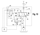
- Figures 9 and 10 differ in that the switching valve 78, analogous to the embodiments shown in Figures 5 and 6, once without and once with bypass line 72 with check valve 74 is executed ( Figure 9 and Figure 10).
- a pressure reduction in the control pressure line is ensured here as well via a return possibility of the hydraulic control pressure fluid in the closed position of the switching valve 72 (FIG. 9) or via a check valve 74 (FIG. 10) arranged separately in the bypass line 72.
- electro-proportional pressure reducing valve 82 in the embodiments of Figures 7 to 10 with a serving as a control pressure source hydraulic line 52 connected pressure sensor 88 is arranged with which a pressure in the brake system 14 of Towing vehicle 10 can be detected. Both the pressure sensor 88 and the electro-proportional pressure reducing valve 82 and the adjusting device 86 are connected to the electronic control 38. Corresponding control signals for the Electro-proportional pressure reducing valve 82 can be predetermined or generated by the adjusting device 44 in conjunction with the electronic control 38. It can also be provided in the embodiments according to the figures 7 to 10, as already to the embodiment described in Figure 4, a pressure sensor 77 which is arranged in the brake pipe 54 of the trailer 12.
- An essential feature for all exemplary embodiments illustrated in FIGS. 7 to 10 is that initially limiting the maximum brake pressure for the trailer 12 by limiting the control pressure in the second control pressure line 60 via the adjustable pressure reducing valve 66 or via the adjustable switching valve 78 analogous to the In the figures 2 to 6 illustrated embodiments takes place.
- a deceleration of the trailer 12 can occur in the event of failure of the electrical system. It is important that this maximum brake pressure is fixed and should not be adjustable (except for the difference 100 bar and 120 bar, which may be useful for reasons of variety of parts, so that one and the same pressure reducing valve 66, for example, the specifications for 100 bar and for The brake characteristic or the characteristic curve K of the trailer brake valve 56 is designed or set in a basic setting so that in the basic position of the electro-proportional pressure reducing valve 82, the vehicle combination (10, 12) in its most unfavorable State with respect to the French rule can be braked without violating the rule (eg, lower characteristic K in Figure 11). It is of course also another (greater or lesser) slope of the characteristic curve K of the trailer brake valve 56 conceivable, but the vehicle should not be braked too aggressively, since this mode is required only in case of failure of
- the characteristic K which represents a smaller slope and a minimum maximum pressure (lower characteristic in Figure 11) reflects the braking behavior of the trailer brake valve 56 in case of failure of the electronics again.
- This basic setting of the control pressure for the trailer brake valve 56 is now superimposed by a further control pressure, which is generated by the electro-proportional pressure reducing valve 82 and the associated hydraulic supply line to the hydraulic pump 32.
- the electronic control 38 evaluates the pressure measured in the brake system 14 of the towing vehicle 10 with the illustrated pressure sensor 88 and calculates the pressure signal to be generated by the electroproportional pressure reducing valve 82 based on the characteristic curve K predetermined by the operator via the setting device 44, whereupon the pressure is controlled by the electronic control 38 generated control of the adjustment 86 takes place.
Abstract
Description
Die Erfindung betrifft eine hydraulische Anordnung zum Bremsen eines Anhängers, mit einer mit einer Bremsanlage eines Anhängers hydraulisch verbindbaren Bremsleitung, einer Hydraulikquelle, einem Hydrauliktank, einem die Hydraulikquelle und den Tank mit der Bremsleitung verbindenden, hydraulisch ansteuerbaren Anhängerbremsventil, einer sich zwischen der Bremsleitung und dem Anhängerbremsventil erstreckenden ersten Steuerdruckleitung, einer sich zwischen dem Anhängerbremsventil und einer Steuerdruckquelle erstreckenden zweiten Steuerdruckleitung und einem in der zweiten Steuerdruckleitung angeordneten, einstellbaren, Druck reduzierenden Mittel zur Steuerung des Steuerdrucks.The invention relates to a hydraulic arrangement for braking a trailer, with a hydraulically connectable to a brake system of a trailer brake line, a hydraulic source, a hydraulic tank, a hydraulic source and the tank with the brake line connecting, hydraulically controllable trailer brake valve, a between the brake line and the Trailer brake valve extending first control pressure line, a extending between the trailer brake valve and a control pressure source second control pressure line and arranged in the second control pressure line, adjustable, pressure reducing means for controlling the control pressure.
Bei Zugfahrzeugen mit einem oder mehreren Anhängern müssen besondere Vorgaben hinsichtlich der Bremsanlage des Anhängers eingehalten werden, insbesondere wenn es sich dabei um hydraulische Bremsanlagen am Anhänger handelt. Die Vorgaben und Richtlinien für hydraulische Anhängerbremsanlagen sind von Staat zu Staat verschieden, was dazu führt, dass die Bremsanlagen möglichst variabel einstellbar ausgebildet sein müssen, um den verschiedenen Anforderungen gerecht zu werden und um möglichst universell einsetzbar zu sein. Insbesondere bei der Gewährleistung eines maximalen Anhängerbremsdrucks werden unterschiedliche Standards in Europa angewandt. Dabei muss in den meisten Ländern Europas der maximale Anhängerbremsdruck bei voller Bremsung des Zugfahrzeugs zwischen 100 und 150 bar liegen. In Frankreich muss der maximale Anhängerbremsdruck bei voller Bremsung des Zugfahrzeugs sogar zwischen 120 und 150 bar liegen. Ferner darf, wenn die Bremse des Zugfahrzeuges nicht betätigt ist, am Anhänger kein Bremsdruck anstehen. Zusätzlich muss beispielsweise in Frankreich am Anhänger ein Druck von 100 bar anstehen, wenn das Zugfahrzeug mit einer Verzögerung von 25% bis 35% abgebremst wird. Es ergeben sich somit einige grundsätzliche Probleme, die im Folgenden aufgelistet werden: Ein unbeladener Anhänger wird bei gleichem Bremsdruck stärker abgebremst als ein beladener Anhänger. Es kann somit ein Über- oder Unterbremsen des Anhängers und damit ein Einknicken des gesamten Zuges stattfinden. Ein unbeladenes Zugfahrzeug wird bei gleichem Bremsdruck stärker abgebremst als ein beladenes Zugfahrzeug. Es kann somit auch hier ein Über- oder Unterbremsen des Anhängers und somit ein Einknicken des gesamten Zuges stattfinden. Bei gleichem Bremsdruck erzeugen große Reifendurchmesser eine geringere Verzögerungskraft als kleine Reifendurchmesser. Dieses gilt auch für neue und abgefahrene Reifen. Aufgrund dieser Problemstellung ist es schwierig, eine richtige Abstimmung des hydraulischen Anhängerbremsventils für einen gesamten Zug zu finden.For towing vehicles with one or more trailers, special requirements must be met with regard to the trailer's braking system, especially if these are hydraulic brake systems on the trailer. The specifications and guidelines for hydraulic trailer brake systems vary from state to state, which means that the brake systems must be designed as variable as possible to meet the various requirements and to be as universally applicable. In particular, ensuring maximum trailer brake pressure applies different standards in Europe. In most European countries, the maximum trailer brake pressure must be between 100 and 150 bar when the towing vehicle is fully braked. In France, the maximum trailer brake pressure at full braking of the towing vehicle must be between 120 and 150 bar. Furthermore, if the brake of the towing vehicle is not actuated, there must be no brake pressure on the trailer. In addition, for example, in France on the trailer, a pressure of 100 bar when the towing vehicle decelerates with a deceleration of 25% to 35%. There are thus some fundamental problems, which are listed below: An unloaded trailer is braked more at the same brake pressure than a loaded trailer. It can thus take place over or under braking of the trailer and thus buckling of the entire train. An unloaded towing vehicle is slowed down more at the same brake pressure than a loaded towing vehicle. It can thus take place here too over or under braking of the trailer and thus buckling of the entire train. At the same brake pressure, large tire diameters produce a lower deceleration force than small tire diameters. This also applies to new and worn tires. Due to this problem, it is difficult to find a proper tuning of the hydraulic trailer brake valve for an entire train.
Im Stand der Technik sind so genannte Anpassungsventile bekannt, die den max. Bremsdruck am Anhänger begrenzen. In der Ausgabe Nr. 8, 2005, Seiten 54 und 55 der Fachzeitschrift "PROFI" wird beispielsweise eine hydraulische Anordnung zu einem Bremssystem der Firma Paul Forrer AG offenbart, bei dem über ein Lastanpassungsventil in der Bremsleitung des Anhängers ein variabler Bremsdruck für den Anhänger einstellbar ist, so dass das Bremsverhalten den unterschiedlichen Beladungszuständen des Anhängers angepasst werden kann. Nachteilig wirkt sich hier aus, dass die Einstellung des Lasthalteventils außerhalb einer Kabine des Zugfahrzeugs manuell erfolgen muss. Zudem ist diese Lösung mit erheblichen Leistungsverlusten verbunden, da ein bereits erzeugter Bremsdruck in der Bremsleitung nachträglich begrenzt und der verbleibende Bremsdrucküberschuss somit vergeudet wird.In the prior art, so-called adjustment valves are known, the max. Limit brake pressure on the trailer. Issue No. 8, 2005,
Die der Erfindung zugrunde liegende Aufgabe wird darin gesehen, eine hydraulische Anordnung der eingangs genannten Art anzugeben, durch welches die vorgenannten Probleme überwunden werden.The object underlying the invention is seen to provide a hydraulic arrangement of the type mentioned, by which the aforementioned problems are overcome.
Die Aufgabe wird erfindungsgemäß durch die Lehre des Patentanspruchs 1 gelöst. Weitere vorteilhafte Ausgestaltungen und Weiterbildungen der Erfindung gehen aus den Unteransprüchen hervor.The object is achieved by the teaching of claim 1. Further advantageous embodiments and modifications of the invention will become apparent from the dependent claims.
Erfindungsgemäß umfasst eine hydraulische Anordnung der eingangs genannten Art eine Steuerdruckquelle, die als Teil des Hydraulikkreises einer Bremsanlage eines den Anhänger ziehenden Zugfahrzeugs ausgebildet ist, wobei das den Druck reduzierende Mittel durch eine einstellbare Vorspannkraft mechanisch in eine geöffnete Grundstellung zwingbar ist. Dadurch, dass die Steuerdruckquelle als Teil des Hydraulikkreises der Bremsanlage des Zugfahrzeugs ausgebildet ist, kann durch Erzeugen eines Bremsdrucks im Zugfahrzeug, beispielsweise durch Treten des Bremspedals, ein Steuerdruck in der zweiten Steuerdruckleitung generiert werden. Gleichzeitig befindet sich das Druck reduzierende Mittel in einer geöffneten Grundstellung, so dass auch bei Ausfall einer Elektroniksteuerung am Zugfahrzeug, die Funktionalität der hydraulischen Bremsanlage für den Anhänger gewährleistet ist. Ferner erfolgt durch die Anordnung des Druck reduzierenden Mittels in der zweiten Steuerdruckleitung eine Begrenzung des Bremsdrucks für die Bremsanlage des Anhängers nicht erst in der Bremsleitung, also in einer großvolumigen Leitung, sondern bereits in der zweiten Steuerleitung für das Anhängerbremsventil, also in einer kleinvolumigen Leitung, so dass Leistungsverluste minimiert werden können.According to the invention, a hydraulic arrangement of the aforementioned type comprises a control pressure source, which is formed as part of the hydraulic circuit of a brake system of a towing vehicle pulling the trailer, wherein the pressure reducing means by an adjustable biasing force mechanically in an open basic position is zwingbar. Characterized in that the control pressure source is formed as part of the hydraulic circuit of the brake system of the towing vehicle, a control pressure in the second control pressure line can be generated by generating a brake pressure in the towing vehicle, for example by pressing the brake pedal. At the same time, the pressure reducing means is in an open basic position, so that even if an electronic control fails on the towing vehicle, the functionality of the hydraulic brake system for the trailer is guaranteed. Furthermore, by the arrangement of the pressure-reducing means in the second control pressure line, a limitation of the brake pressure for the brake system of the trailer not only in the brake line, ie in a large-volume line, but already in the second control line for the Trailer brake valve, so in a small volume line, so that power losses can be minimized.
Die Steuerdruckquelle kann beispielsweise als eine mit der Bremsanlage des Zugfahrzeugs verbundene hydraulische Leitung ausgebildet sein. Dies führt dazu, dass die zweite Steuerdruckleitung direkt von der Bremsleitung abzweigbar ist, so dass stets, wenn ein Druck in der Bremsleitung des Zugfahrzeugs aufgebaut wird, ein Steuerdruck zur Steuerung des Anhängerbremsventils ansteht. Die Steuerdruckleitung kann dabei direkt abgezweigt oder indirekt, beispielsweise über ein Verbindungsteil oder ein Ventil, mit der Bremsleitung oder einer anderen einen Bremsdruck bzw. einen Druck führenden Leitung der Bremsanlage des Zugfahrzeugs verbunden sein.The control pressure source can be designed, for example, as a hydraulic line connected to the brake system of the towing vehicle. As a result, the second control pressure line can be branched off directly from the brake line, so that whenever a pressure is built up in the brake line of the towing vehicle, a control pressure is present for controlling the trailer brake valve. The control pressure line can be branched off directly or connected indirectly, for example via a connecting part or a valve, with the brake line or another brake pressure or a pressure line leading the brake system of the towing vehicle.
Das Druck reduzierende Mittel in der zweiten Steuerdruckleitung ist als einstellbares, hydraulisch schaltbares Druckreduzierventil ausgebildet. Dabei ist das Druckreduzierventil derart ausgebildet, dass die Vorspannkraft von einer Bedienperson einstellbar bzw. justierbar ist, sei es durch manuelle, elektrische oder hydraulische Mittel, wobei stets gewährleistet wird, dass eine voreingestellte Vorspannkraft unabhängig von hydraulischen oder elektrischen Mitteln angreift. Über eine Pilotdruckleitung, die von der zweiten Steuerdruckleitung anhängerbremsventilseitig zum Druckreduzierventil führt, kann das Druckreduzierventil in eine Schließstellung gebracht werden, vorausgesetzt, dass der in der Steuerdruckleitung herrschende Druck die voreingestellte Vorspannkraft überwindet. Sollte sich somit in der zweiten Steuerdruckleitung ein Steuerdruck einstellen, der den voreingestellten Wert übersteigt, wird das Druckreduzierventil in Schließstellung gebracht. Somit kann das Anhängerbremsventil bis zu einem voreingestellten Druck für die zweite Steuerdruckleitung entsprechend dem vom Bremssystem für das Zugfahrzeug bzw. dem von der Steuerdruckquelle generierten Druck variabel angesteuert werden.The pressure reducing means in the second control pressure line is designed as an adjustable, hydraulically switchable pressure reducing valve. In this case, the pressure reducing valve is designed such that the biasing force is adjustable or adjustable by an operator, be it by manual, electric or hydraulic means, whereby it is always ensured that a pre-set biasing force acts independently of hydraulic or electrical means. Via a pilot pressure line leading from the second control pressure line trailer brake valve side to the pressure reducing valve, the pressure reducing valve can be brought into a closed position, provided that the pressure prevailing in the control pressure line overcomes the preset biasing force. Should therefore set in the second control pressure line, a control pressure that exceeds the preset value, the pressure reducing valve is brought into the closed position. Thus, can the trailer brake valve is variably driven up to a preset pressure for the second control pressure line according to the pressure generated by the brake system for the towing vehicle or the pressure generated by the control pressure source.
Eine Bypassleitung, die dem Druckreduzierventil parallel geschaltet ist ermöglicht die Anordnung eines Rückschlagventils, welches in Richtung des Anhängerbremsventils geschlossen ist und durch welches ein Rückströmen von Hydraulikflüssigkeit aus der zweiten Steuerdruckleitung vereinfacht bzw. beschleunigt wird.A bypass line which is connected in parallel to the pressure reducing valve allows the arrangement of a check valve, which is closed in the direction of the trailer brake valve and by which a return flow of hydraulic fluid from the second control pressure line is simplified or accelerated.
Das Druckreduzierventil kann als herkömmliches Druckreduzierventil, welches ab einen bestimmten Steuerdruck in der zweiten Steuerdruckleitung die zweite Steuerdruckleitung schließt, oder aber als Schaltventil ausgebildet sein, welches ab einen bestimmten Druck in der Bremsleitung die zweite Steuerdruckleitung in beide Richtungen oder zumindest in Richtung zum Anhängerbremsventil schließt. Im Falle des Schaltventils ist dieses über eine Pilotdruckleitung mit der Bremsleitung des Anhängers verbunden, so dass, bei Erreichen eines maximalen Bremsdrucks, das Schaltventil hydraulisch angesteuert schließt.The pressure reducing valve may be formed as a conventional pressure reducing valve, which closes the second control pressure line from a certain control pressure in the second control pressure line, or as a switching valve which closes the second control pressure line in both directions or at least in the direction of the trailer brake valve from a certain pressure in the brake line. In the case of the switching valve, this is connected via a pilot pressure line to the brake line of the trailer, so that, when a maximum brake pressure, the switching valve closes hydraulically closes.
Das Druckreduzierventil weist vorzugsweise eine verstellbare Vorspannfeder aufweist, mit welcher die Vorspannkraft erzeugt wird, die das Druckreduzierventil in eine geöffnete Grundstellung zwingt. Die Vorspannfeder kann dabei von einer Bedienperson manuell oder elektrisch verstellt werden. Durch die Vorspannkraft der Verstellfeder wird rein mechanisch vorgegeben, bei welchem maximalen Druck das Druckreduzierventil schließen soll, so dass auch bei Ausfall einer das Bremssystem des Anhängers oder des Zugfahrzeugs oder Komponenten von diesen steuernden Elektronik ein den Anhänger bremsender und vom Bremssystem des Zugfahrzeugs abgezweigter Bremsdruck aufgebaut wird. Durch Verstellen der Vorspannfeder erfolgt die Einstellung eines maximalen Bremsdrucks für den Anhänger. Dadurch kann der Steuerdruck in der Steuerdruckleitung, der das Anhängerbremsventil ansteuert, auf einen bestimmten Maximaldruck eingestellt werden, der entsprechend der zuvor angesprochenen Richtlinien, beispielsweise 100 bar (120 bar in Frankreich) nicht unterschreiten und 150 bar nicht überschreiten darf.The pressure reducing valve preferably has an adjustable biasing spring, with which the biasing force is generated, which forces the pressure reducing valve in an open basic position. The biasing spring can be manually or electrically adjusted by an operator. By the biasing force of the adjusting spring is given purely mechanically, at which maximum pressure the Pressure reducing valve should close, so that even if one of the braking system of the trailer or the towing vehicle or components of these controlling electronics, a braking the trailer and the brake system of the towing vehicle branched brake pressure is built up. Adjusting the preload spring sets a maximum brake pressure for the trailer. As a result, the control pressure in the control pressure line, which controls the trailer brake valve, can be set to a specific maximum pressure which, in accordance with the previously mentioned guidelines, for example 100 bar (120 bar in France), must not fall below 150 bar.
Das Druckreduzierventil kann elektronische Verstellmittel aufweisen, die es ermöglichen, eine Stellkraft zu erzeugen, die der Vorspannkraft der Vorspannfeder entgegenwirkt oder diese verstärkt. Derartige elektronische Verstellmittel können beispielsweise als Magnetspulen ausgebildet sein, die eine Auslenkung der Vorspannfeder beeinflussen, d. h. vergrößern oder verringern. In diesen Fällen muss die Vorspannfeder so stark eingestellt sein, dass bei Ausfall einer Elektrik die eingangs genannten Vorschriften nach wie vor erfüllt werden. Somit darf der max. Anhängerbremsdruck auch hier die 100 bar (120 bar in Frankreich) nicht unterschreiten und die 150 bar nicht überschreiten. Wenn die Feder auf 100 bar (120 bar in Frankreich) eingestellt ist, kann mit zunehmendem elektrischen Steuersignal ein höherer hydraulischer Druck aufgebaut werden, um das Druckreduzierventil, welches, wie oben erwähnt, als Druckreduzierventil oder auch als Schaltventil ausgebildet sein kann, zu schalten. Die Vorspannfeder kann in diesem Fall elektronisch um bis zu 50 bar proportional verstärkt werden. Wenn die Feder auf 150 bar eingestellt ist, muss mit zunehmendem elektronischem Steuersignal ein geringerer hydraulischer Druck aufgebaut werden, um das Druckreduzierventil zu schalten. Die Vorspannfeder kann in diesem Fall elektronisch um bis zu 50 bar proportional entlastet werden. Bei einem Ausfall der Elektrik würde der Anhänger immer noch abgebremst werden können, wobei der Maximaldruck entweder 100 bar (120 bar in Frankreich) oder 150 bar betragen könnte. Auch bei Einsatz von Schaltventilen an Stelle von Druckreduzierventilen als Druckreduzierventile, können elektronische Verstellungen bzw. Ansteuerungen der Vorspannfeder angewendet werden, so dass die gleichen elektronischen Mittel verstärkend oder entlastend wirken, um bei Ausfall der Elektrik den Anhänger mit max. 100 bar oder 150 bar bremsen zu können. Dabei ist hier nicht der in der zweiten Steuerdruckleitung wirkende Steuerdruck ausschlaggebend, sondern der in der Bremsleitung für den Anhänger wirkende Druck, wie oben beschrieben.The pressure reducing valve may comprise electronic adjusting means which make it possible to generate a force which counteracts or enhances the biasing force of the biasing spring. Such electronic adjusting means may be formed, for example, as magnetic coils, which influence a deflection of the biasing spring, ie increase or decrease. In these cases, the preload spring must be set so strong that in case of failure of an electrical system, the rules mentioned above are still met. Thus, the max. Trailer brake pressure not less than 100 bar (120 bar in France) and not exceeding 150 bar. If the spring is set to 100 bar (120 bar in France), with increasing electrical control signal, a higher hydraulic pressure can be built to switch the pressure reducing valve, which, as mentioned above, can be designed as a pressure reducing valve or as a switching valve. In this case, the preload spring can be electronically amplified by up to 50 bar. If the spring is set to 150 bar, must with increasing electronic control signal, a lower hydraulic pressure are built to switch the pressure reducing valve. The preload spring can be relieved electronically by up to 50 bar in this case. In the event of a failure of the electrical system, the trailer would still be able to be braked, the maximum pressure being either 100 bar (120 bar in France) or 150 bar. Even with the use of switching valves in place of pressure reducing valves as pressure reducing valves, electronic adjustments or controls of the biasing spring can be applied so that the same electronic means amplifying or relieving, in case of failure of the electrical system, the trailer with max. 100 bar or 150 bar to brake. In this case, it is not the control pressure acting in the second control pressure line which is decisive, but the pressure acting in the brake line for the trailer, as described above.
Das Anhängerbremsventil kann als proportionales Schieberventil ausgebildet sein, welches hydraulisch über die erste Steuerdruckleitung seitens der Bremsleitung des Anhängers sowie hydraulisch über die zweite Steuerdruckleitung seitens der Bremsanlage des Zugfahrzeugs ansteuerbar ist. Das Anhängerbremsventil ist dabei so ausgebildet, dass mit größer werdendem Steuerdruck in der zweiten Steuerdruckleitung sich der Schieber proportional verschiebt bzw. zunehmend öffnet, so dass sich ein höherer Bremsdruck durch die von der Hydraulikquelle geförderte Hydraulikflüssigkeit einstellt. Dabei stellt sich bei maximalem Bremsdruck für den Anhänger ein Gleichgewicht ein, da der Druck seitens der Bremsleitung in der ersten Steuerdruckleitung dem Druck in der zweiten Steuerdruckleitung entgegenwirkt. Ist die zweite Steuerdruckleitung hingegen nicht druckbeaufschlagt, d.h. die Bremsanlage des Zugfahrzeugs wird nicht betätigt, so dass sich kein Steuerdruck weiter aufbaut, wird das Schieberventil in die entgegen gesetzte Richtung bewegt und der Druck baut sich über das Schieberventil ab, indem die zuvor geförderte Hydraulikflüssigkeit in Richtung des Hydrauliktanks abfließen kann.The trailer brake valve may be formed as a proportional slide valve, which is hydraulically actuated via the first control pressure line from the brake line of the trailer and hydraulically via the second control pressure line from the brake system of the towing vehicle. The trailer brake valve is designed so that with increasing control pressure in the second control pressure line, the slide shifts proportionally or increasingly opens, so that sets a higher brake pressure by the funded by the hydraulic source hydraulic fluid. In this case, at maximum brake pressure for the trailer equilibrium, since the pressure on the part of the brake line in the first control pressure line counteracts the pressure in the second control pressure line. Is the second one Control pressure line, however, not pressurized, ie the brake system of the towing vehicle is not actuated so that no control pressure builds up further, the slide valve is moved in the opposite direction and the pressure builds up on the slide valve by the previously funded hydraulic fluid in the direction of the hydraulic tank can drain away.
Eine dritte Steuerdruckleitung kann vorgesehen sein, mit welcher das Anhängerbremsventil zusätzlich zur ersten und zweiten Steuerdruckleitung hydraulisch ansteuerbar ist. Die dritte Steuerdruckleitung ist dabei vorzugsweise mit einem elektronisch verstellbaren Druckreduzierventil versehen, welches die Hydraulikquelle und den Hydrauliktank mit der dritten Steuerdruckleitung verbindet. Die zusätzliche Ansteuerung des Anhängerbremsventils kann zu einer Kennfeldänderung des Anhängerbremsventils genutzt werden, so dass durch Aufbringen eines zusätzlichen Steuerdrucks das Bremsverhalten des Anhängers flexibel gestaltet werden kann. Die Anordnung der dritten Steuerdruckleitung erfolgt dabei vorzugsweise parallel zur zweiten Steuerdruckleitung. Das Wesentliche bei diesem Ausführungsbeispiel ist weiterhin zunächst die Begrenzung des maximalen Anhängerbremsdruckes durch den maximalen Steuerdruck in der zweiten Steuerdruckleitung auf einen Wert von 100 bar bzw. 120 bar, wie zuvor erläutert. Der Begrenzungsdruck kann dabei fest eingestellt und nicht elektronisch verstellbar sein, bis auf den Unterschied von 100 bar und 120 bar. Das Bremsverhalten bzw. das Verhalten des Schieberventils ist dadurch derart ausgelegt, dass das Fahrzeug samt Anhänger in seinem ungünstigsten Zustand bezüglich der französischen Vorschrift abgebremst werden kann. Diese Grundeinstellung des Steuersignals durch den Steuerdruck in der zweiten Steuerdruckleitung auf den Anhängerbremsventilschieber wird nun von dem Steuerdruck der dritten Steuerdruckleitung überlagert, welcher durch das zwischen der dritten Steuerdruckleitung und der Hydraulikquelle bzw. Hydrauliktank angeordnete elektroproportionale Druckreduzierventil eingestellt wird. Durch den zusätzlichen dritten Steuerdruck kann das Schieberventil in einem größeren Maße ausgelenkt werden und damit eine größere Bremswirkung erzielt werden. Es findet somit eine Überlagerung der beiden Drücke statt und es ist möglich, das Kennfeld des Anhängerbremsventils frei innerhalb vorgegebener Grenzen zu verändern und so das Bremsverhalten des gesamten Zuges positiv bezüglich des Fahrverhaltens einzustellen.A third control pressure line may be provided, with which the trailer brake valve is hydraulically controllable in addition to the first and second control pressure line. The third control pressure line is preferably provided with an electronically adjustable pressure reducing valve which connects the hydraulic source and the hydraulic tank with the third control pressure line. The additional control of the trailer brake valve can be used to a map change of the trailer brake valve, so that by applying an additional control pressure, the braking behavior of the trailer can be made flexible. The arrangement of the third control pressure line is preferably carried out parallel to the second control pressure line. The essence of this embodiment is further the limitation of the maximum trailer brake pressure by the maximum control pressure in the second control pressure line to a value of 100 bar or 120 bar, as previously explained. The limiting pressure can be fixed and not electronically adjustable, except for the difference of 100 bar and 120 bar. The braking behavior or the behavior of the slide valve is thereby designed so that the vehicle and its trailer can be braked in its most unfavorable condition with regard to the French regulation. This basic setting of the Control signal by the control pressure in the second control pressure line to the trailer brake valve spool is now superimposed by the control pressure of the third control pressure line, which is adjusted by the arranged between the third control pressure line and the hydraulic source or hydraulic tank elektroproportionalale pressure reducing valve. Due to the additional third control pressure, the slide valve can be deflected to a greater extent and thus a greater braking effect can be achieved. It thus takes place a superposition of the two pressures and it is possible to change the map of the trailer brake valve freely within predetermined limits and so to set the braking behavior of the entire train positive with respect to the driving behavior.
In weiteren Ausführungsbeispielen ist ein Drucksensor vorgesehen, mit welchem der Druck der Bremsanlage des Zugfahrzeugs ermittelbar ist. Der mittels des Drucksensors gemessene Druck in der Bremsanlage des Zugfahrzeugs kann dann zur weiteren Verarbeitung und Optimierung der hydraulischen Anordnung herangezogen werden.In further embodiments, a pressure sensor is provided, with which the pressure of the brake system of the towing vehicle can be determined. The measured by the pressure sensor pressure in the brake system of the towing vehicle can then be used for further processing and optimization of the hydraulic arrangement.
Es kann ein Drucksensor vorgesehen sein, der in der Bremsleitung des Anhängers angeordnet ist, wobei dies für die Funktion der hydraulischen Anordnung nicht zwingend erforderlich ist, jedoch eine genauere Einstellungen bzw. Regelung des Anhängerbremsdrucks erzielt werden kann. Der Vorteil käme einem geschlossenen Regelkreis gleich, bei dem der Ausgangsdruck der hydraulischen Anordnung bzw. der Anhängerbremsdruck laufend überwacht und dadurch eine vorgesehene Regelung verbessert wird.It can be provided a pressure sensor which is arranged in the brake line of the trailer, which is not absolutely necessary for the function of the hydraulic arrangement, however, a more accurate settings or control of the trailer brake pressure can be achieved. The advantage would be equivalent to a closed loop, in which the output pressure of the hydraulic arrangement or the trailer brake pressure continuously monitored and thereby an intended control is improved.
Eine elektronische Steuereinheit zur Steuerung bzw. Regelung elektronisch verstellbarer oder schaltbarer Ventile sowie zur Verarbeitung elektronischer Sensorsignale bewertet hierbei den durch den Drucksensor bzw. die Drucksensoren gemessenen Druck im Bremssystem des Zugfahrzeugs und berechnet anhand der von der Bedienperson vorgegebenen Kennlinie für das Anhängerbremsventil den vom Druckreduzierventil in der dritten Steuerdruckleitung zu erzeugenden Steuerdruck, welcher dann den Anhängerbremsventilschieber weiter auslenkt, als dies nur durch den in der zweiten Steuerdruckleitung durch das Bremssignal der Bremsanlage des Zugfahrzeugs erzeugten Steuerdruck möglich wäre. Es findet somit eine Überlagerung der Steuerdrücke in der zweiten und dritten Steuerdruckleitung statt. Es ist somit möglich, das Kennfeld des Anhängerbremsventils frei innerhalb vorgegebener Grenzen zu verändern und so das Bremsverhalten des gesamten Zuges positiv bezüglich des Fahrverhaltens einzustellen. So ist es auch denkbar, dass eine bestimmte Intelligenz in der elektronischen Steuerung hinterlegt wird, die beispielsweise anhand der Druckanstiegsgeschwindigkeit im Zugfahrzeug erkennt, ob es sich um eine Notbremsung handelt, um dann den Anhänger wesentlich schneller und stärker als normal abzubremsen. Als Versorgungsdruck des elektrischen Druckreduzierventils in der dritten Steuerdruckleitung kann der von der Hydraulikquelle erzeugte Druck je nach Bedarf gedrosselt oder ungedrosselt angewandt werden. Dieses ist aus bautechnischen Gründen vorteilhaft, da dieser Druck als Versorgungsdruck für das Bremssystem des Anhängers benötigt wird und somit eine kompaktere Bauweise ermöglicht wird.An electronic control unit for controlling or regulating electronically adjustable or switchable valves and for processing electronic sensor signals evaluates the pressure measured in the brake system of the towing vehicle by the pressure sensor or pressure sensors and calculates the pressure reduction valve in accordance with the characteristic curve for the trailer brake valve specified by the operator the third control pressure line to be generated control pressure, which then deflects the trailer brake valve spool further than would be possible only by the control pressure generated in the second control pressure line by the brake signal of the towing vehicle of the towing vehicle. Thus, there is a superposition of the control pressures in the second and third control pressure line. It is thus possible to change the map of the trailer brake valve freely within predetermined limits and so to set the braking behavior of the entire train positive with respect to the driving behavior. So it is also conceivable that a certain intelligence is stored in the electronic control, which recognizes, for example, based on the pressure rise speed in the towing vehicle, whether it is an emergency braking, then slow down the trailer much faster and stronger than normal. As the supply pressure of the electric pressure reducing valve in the third control pressure line, the pressure generated by the hydraulic source can be throttled or unthrottled as needed. This is advantageous for constructional reasons, since this pressure is needed as supply pressure for the brake system of the trailer and thus a more compact design is made possible.
Eine erfindungsgemäße hydraulische Anordnung eignet sich besonders für eine Kombination aus Anhänger und Zugfahrzeug im landwirtschaftlichen Betrieb, wobei eine hydraulische Bremsanlage für den Anhänger und eine hydraulische Bremsanlage für das Zugfahrzeug vorgesehen ist. Es sind jedoch auch andere Einsatzgebiete denkbar, in denen eine Kombination aus Zugfahrzeug und Anhänger mit hydraulische Bremsanlagen zum Einsatz kommen und eine erfindungsgemäße hydraulische Anordnung Anwendung finden kann, beispielsweise im Bereich von Nutzfahrzeugen oder sogar im Bereich von Personenkraftwagen.A hydraulic arrangement according to the invention is particularly suitable for a combination of trailer and towing vehicle in agricultural operation, wherein a hydraulic brake system for the trailer and a hydraulic brake system is provided for the towing vehicle. However, other applications are conceivable in which a combination of towing vehicle and trailer with hydraulic brake systems are used and a hydraulic arrangement according to the invention can be used, for example in the field of commercial vehicles or even in the field of passenger cars.
Die Vorteile der Erfindung liegen insbesondere darin, dass es für eine Bedienperson möglich ist den Ladezustand seines Anhängers durch eine einfache Verstellung für die Abbremsung seiner gesamten Fahrzeugkombination zu berücksichtigen. Ferner kann er von der Kabine aus seinen maximalen Anhängerbremsdruck verstellen und so während der Fahrt das Abbremsverhalten seiner gesamten Fahrzeugkombination optimieren. Des Weiteren kann er von der Kabine aus das Kennfeld seines Anhängerbremsventils der jeweiligen Reifengröße und dem Gesamtgewicht seines Zugfahrzeugs anpassen. Wenn kein Anhänger betrieben wird, kann im normalen Betrieb Energie gespart werden, da die Kennlinie auf ihren minimalen Maximaldruck eingestellt werden kann. Sollte es zu einem Ausfall der Elektrik kommen, kann der Zug immer noch kontrolliert abgebremst werden.The advantages of the invention are in particular that it is possible for an operator to consider the state of charge of his trailer by a simple adjustment for the deceleration of his entire vehicle combination. Furthermore, he can adjust his maximum trailer brake pressure from the cabin and so optimize the braking behavior of his entire vehicle combination while driving. Furthermore, he can customize the map of his trailer brake valve of the respective tire size and the total weight of his towing vehicle from the cabin. If no trailer is operated, energy can be saved during normal operation because the characteristic can be set to its minimum maximum pressure. Should it come to a failure of the electrical system, the train can still be braked controlled.
Anhand der Zeichnung, die ein Ausführungsbeispiel der Erfindung zeigt, werden nachfolgend die Erfindung sowie weitere Vorteile und vorteilhafte Weiterbildungen und Ausgestaltungen der Erfindung näher beschrieben und erläutert.Reference to the drawing, which shows an embodiment of the invention, the invention and further advantages and advantageous developments and refinements of the invention are described and explained in more detail below.
Es zeigt:
- Fig. 1
- eine Kombination aus Zugfahrzeug und Anhänger mit einer erfindungsgemäßen hydraulischen Anordnung,
- Fig. 2
- einen schematischen Hydraulikschaltplan einer erfindungsgemäßen hydraulischen Anordnung mit manueller Verstellung eines Druckreduzierventils,
- Fig. 3
- einen schematischen Hydraulikschaltplan einer erfindungsgemäßen hydraulischen Anordnung mit manueller Verstellung eines Druckreduzierventils und Bypassleitung,
- Fig. 4
- einen schematischen Hydraulikschaltplan einer erfindungsgemäßen hydraulischen Anordnung mit elektronischer Verstellung eines Druckreduzierventils und Bypassleitung,
- Fig. 5
- einen schematischen Hydraulikschaltplan einer erfindungsgemäßen hydraulischen Anordnung mit elektronischer Verstellung eines Schaltventils und Bypassleitung,
- Fig. 6
- einen schematischen Hydraulikschaltplan einer erfindungsgemäßen hydraulischen Anordnung mit elektronischer Verstellung eines Schaltventils ohne Bypassleitung,
- Fig. 7
- einen schematischen Hydraulikschaltplan einer erfindungsgemäßen hydraulischen Anordnung mit manueller Verstellung eines Druckreduzierventils ohne Bypassleitung und mit zusätzlicher Steuerdruckleitung und Drucksensor,
- Fig. 8
- einen schematischen Hydraulikschaltplan einer erfindungsgemäßen hydraulischen Anordnung mit manueller Verstellung eines Druckreduzierventils mit Bypassleitung und mit zusätzlicher Steuerdruckleitung und Drucksensor,
- Fig. 9
- einen schematischen Hydraulikschaltplan einer erfindungsgemäßen hydraulischen Anordnung mit manueller Verstellung eines Schaltventils ohne Bypassleitung und mit zusätzlicher Steuerdruckleitung und Drucksensor,
- Fig. 10
- einen schematischen Hydraulikschaltplan einer erfindungsgemäßen hydraulischen Anordnung mit manueller Verstellung eines Schaltventils mit Bypassleitung und mit zusätzlicher Steuerdruckleitung und Drucksensor und
- Fig. 11
- ein Diagramm eines Kennlinienfeldes für ein Anhängerbremsventil mit variabler Kennlinie.
- Fig. 1
- a combination of towing vehicle and trailer with a hydraulic arrangement according to the invention,
- Fig. 2
- FIG. 2 shows a schematic hydraulic circuit diagram of a hydraulic arrangement according to the invention with manual adjustment of a pressure-reducing valve, FIG.
- Fig. 3
- FIG. 2 shows a schematic hydraulic circuit diagram of a hydraulic arrangement according to the invention with manual adjustment of a pressure reducing valve and bypass line, FIG.
- Fig. 4
- FIG. 2 shows a schematic hydraulic circuit diagram of a hydraulic arrangement according to the invention with electronic adjustment of a pressure-reducing valve and bypass line, FIG.
- Fig. 5
- FIG. 2 a schematic hydraulic circuit diagram of a hydraulic arrangement according to the invention with electronic adjustment of a switching valve and bypass line, FIG.
- Fig. 6
- FIG. 2 a schematic hydraulic circuit diagram of a hydraulic arrangement according to the invention with electronic adjustment of a switching valve without bypass line, FIG.
- Fig. 7
- a schematic hydraulic circuit diagram of a hydraulic arrangement according to the invention with manual adjustment of a pressure reducing valve without bypass line and with additional control pressure line and pressure sensor,
- Fig. 8
- a schematic hydraulic circuit diagram of a hydraulic arrangement according to the invention with manual adjustment of a pressure reducing valve with bypass line and with additional control pressure line and pressure sensor,
- Fig. 9
- a schematic hydraulic circuit diagram of a hydraulic arrangement according to the invention with manual adjustment of a switching valve without bypass line and with additional control pressure line and pressure sensor,
- Fig. 10
- a schematic hydraulic circuit diagram of a hydraulic arrangement according to the invention with manual adjustment of a switching valve with bypass line and with additional control pressure line and pressure sensor and
- Fig. 11
- a diagram of a characteristic field for a trailer brake valve with a variable characteristic.
Figur 1 zeigt eine Kombination aus einem Zugfahrzeug 10, in Form eines landwirtschaftlichen Schleppers, und einem Anhänger 12. Das Zugfahrzeug 10 und der Anhänger 12 verfügen jeweils über eine hydraulisch betätigbare Bremsanlage 14, 16, wobei die Versorgungs- und Steuerungskomponenten für die Bremsanlagen 14, 16 vorwiegend am Zugfahrzeug 10 angeordnet sind.1 shows a combination of a
Die Bremsanlagen 14, 16 verfügen über hydraulisch betätigbare Bremsmittel 18, 20, welche als mit Rädern 22 des Zugfahrzeugs 10 und mit Rädern 24 des Anhängers 12 in Eingriff bringbare Bremsbacken ausgebildet sind. Die Betätigung der Bremsmittel 18, 20 erfolgt durch hydraulische Druckbeaufschlagung entsprechender Bremsleitungen 26, 28.The
Die Versorgungs- und Steuerungskomponenten für die Bremsanlagen 14, 16 umfassen einen Hydrauliktank 30, eine Hydraulikpumpe 32, eine Hydrauliksteuerung 34 für die Bremsanlage 14 des Zugfahrzeugs 10, eine Hydrauliksteuerung 36 für den Anhänger 12 sowie eine elektronische Steuerung 38 für elektronisch ansteuerbare Komponenten der Hydrauliksteuerungen 36 für das Zugfahrzeug 10 oder den Anhänger 12. In einer Fahrzeugkabine 40 des Zugfahrzeugs 10 sind ein den Bremsdruck auslösendes Bremspedal 42, welches mit der Hydrauliksteuerung 34 der Bremsanlage 14 verbunden ist, sowie eine elektronische Einstelleinrichtung 44, mit der Steuersignale an die elektronische Steuerung 38 generierbar sind, angeordnet. Über eine am Zugfahrzeug 10 angeordnete hydraulische Koppelstelle 46 wird die Bremsanlage 16 des Anhängers 12 mit der Bremsanlage 14 des Zugfahrzeugs 10 hydraulisch verbunden.The supply and control components for the
Die Anordnung und Ausbildung der Hydrauliksteuerung 36 für den Anhänger 12 wird anhand der in den Figuren 2 bis 10 dargestellten Ausführungsbeispiele erläutert.The arrangement and design of the
Figur 2 zeigt ein erstes Ausführungsbeispiel der Hydrauliksteuerung 36 für den Anhänger 12. Die Hydrauliksteuerung 36 verfügt über Anschlussleitungen 48, 50, die die Hydrauliksteuerung 36 mit dem Hydrauliktank 30 und der Hydraulikpumpe 32 verbinden. Ferner ist eine hydraulische Leitung 52 vorgesehen, die eine Verbindung zur Hydrauliksteuerung 34 für das Zugfahrzeug 10, bzw. zur Bremsanlage 14 des Zugfahrzeugs 10 darstellt. Eine Bremsleitung 54 verbindet die Hydrauliksteuerung 36 mit der hydraulischen Koppelstelle 46 des Zugfahrzeugs 10. Die Hydrauliksteuerung 36 umfasst weiterhin ein Anhängerbremsventil 56 welches zwischen den Anschlussleitungen 48, 50 und der Bremsleitung 54 angeordnet ist. Das Anhängerbremsventil 56 ist vorzugsweise als hydraulisch ansteuerbares proportionales Schieberventil ausgebildet, welches über eine mit der Bremsleitung 54 verbundenen ersten Steuerdruckleitung 58 und über eine mit der hydraulischen Leitung 52 verbundenen zweiten Steuerdruckleitung 60 hydraulisch ansteuerbar ist. Die Stellung des Anhängerbremsventils 56 und damit auch der Druck in der Bremsleitung 54 richtet sich folglich nach der am Anhängerbremsventil 56 anliegenden Druckdifferenz zwischen der ersten und zweiten Steuerdruckleitung 58, 60. Das Anhängerbremsventil 56 verbindet in einer ersten Extremstellung 62 den Hydrauliktank 30 und in einer zweiten Extremstellung 64 die Hydraulikpumpe 32 mit der Bremsleitung 54. Da das Anhängerbremsventil 56 als proportional ansteuerbares Schieberventil ausgebildet ist, sind proportional zu den auf das Anhängebremsventil 56 wirkenden Steuerdrücken beliebige Zwischenstellungen möglich. Die zweite Steuerdruckleitung 60 ist mit einem Druck reduzierenden Mittel in Form eines Druckreduzierventils 66 versehen, wobei die hydraulische Leitung 52 als Steuerdruckquelle für die zweite Steuerdruckleitung 60 dient. Hierbei kann auch eine andere Komponente der Bremsanlage 14 des Zugfahrzeugs 10 als Steuerdruckquelle dienen, solange diese mit dem beaufschlagten Bremsdruck der Bremsanlage 14 mittelbar oder unmittelbar in Verbindung steht. Das Druckreduzierventil 66 dient zur Reduzierung bzw. Begrenzung des Steuerdrucks, mit dem die zweite Steuerdruckleitung 60 beaufschlagt wird. Das Druckreduzierventil 66 ist über eine als manuell verstellbare Vorspannfeder 68 ausgebildete Einstelleinrichtung verstellbar und wird dadurch mechanisch in eine voreinstellbare geöffnete Grundstellung gezwungen. Ein entgegen der Vorspannkraft der Vorspannfeder 68 wirkender Steuerdruck wird über eine mit der zweiten Steuerdruckleitung 60 verbundenen dritten Steuerdruckleitung 70 aufgebracht und bewegt das Druckreduzierventil 66 entsprechend der Höhe des Steuerdrucks entgegen der Vorspannkraft in Richtung Schließstellung. Bei Erreichen eines maximalen Steuerdrucks in der zweiten Steuerdruckleitung 60 wird dann das Druckreduzierventil 66 über die dritte Steuerdruckleitung 70 entgegen der eingestellten Vorspannkraft geschlossen. Durch entsprechende Voreinstellung der Vorspannkraft wird somit ein maximaler Steuerdruck in der zweiten Steuerdruckleitung 60 und damit ein maximaler Druck für die Bremsleitung 54 des Anhängers 12 eingestellt. Die Einstellung des maximalen Bremsdrucks für den Anhänger 12 erfolgt wie erwähnt durch Verstellung der Vorspannfeder 68 des Druckreduzierventils. Hierdurch kann der Pilotdruck, der das Anhängerbremsventil 56 verschiebt, auf einen bestimmten Maximaldruck eingestellt werden, der beispielsweise 100 bar oder 120 bar (in Frankreich) nicht unterschreitet und 150 bar nicht überschreitet.Figure 2 shows a first embodiment of the
Figur 3 zeigt ein weiteres Ausführungsbeispiel, bei dem zusätzlich zu dem in Figur 2 dargestellten Ausführungsbeispiel eine Bypassleitung 72 angeordnet ist, mit der das Druckreduzierventil umgangen wird und die sich zwischen der hydraulischen Leitung 52 und der zweiten Steuerdruckleitung 60 erstreckt. Die Bypassleitung 72 weist ein Rückschlagventil 74 auf, welches in Richtung der zweiten Steuerdruckleitung 60 schließt. Das Rückschlagventil 74 erleichtert ein Rückströmen der Hydraulikflüssigkeit bei nachlassendem Bremsdruck, bzw. Steuerdruck in der zweiten Steuerdruckleitung 60. Je nach Ausführung des Druckreduzierventils 66 wird dadurch auch erst ein Rückströmen der Hydraulikflüssigkeit ermöglicht.FIG. 3 shows a further exemplary embodiment in which, in addition to the exemplary embodiment shown in FIG. 2, a
Ein weiteres Ausführungsbeispiel ist in Figur 4 dargestellt. Eine mit der Vorspannfeder 68 in Wechselwirkung tretende elektronische Verstelleinrichtung ermöglicht die elektronische Verstellung des Druckreduzierventils 66 bzw. der Vorspannfeder 68. Durch die Verstelleinrichtung kann die Vorspannfeder elektronisch gesteuert proportional verstärkt oder entlastet werden. Die Verstelleinrichtung ist vorzugsweise als elektronisch ansteuerbare Magnetspule 76 ausgebildet, die über die elektronische Steuerung 38 verstellbar ist. Die Verstellung der Magnetspule 76 bzw. der Verstelleinrichtung erfolgt über die in der Fahrzeugkabine 40 angeordnete Einstelleinrichtung 44, über die entsprechende Steuersignale an die elektronische Steuerung 38 gegeben werden. Die Verstelleinrichtung kann auch als Elektromotor oder als eine andere elektronische Verstelleinrichtung ausgebildet sein, mit der die auf das Druckreduzierventil wirkende Vorspannkraft verstellbar ist. Die Vorspannfeder 68 muss so eingestellt bzw. ausgebildet sein, dass bei Ausfall der Elektronik die Vorschriften nach wie vor erfüllt werden. Somit darf der max. Anhängerbremsdruck beispielsweise 100 bar (120 bar in Frankreich) nicht unter- und 150 bar nicht überschreiten. Wenn die Vorspannfeder 68 beispielsweise auf 100 bar (120 bar in FR) voreingestellt ist, kann die Vorspannfeder 68 entsprechend dem durch die Einstelleinrichtung 44 vorgegebenen elektronischen Signals elektronisch um bis zu 50 bar proportional verstärkt werden, um einen Maximaldruck für das Anhängerbremsventil 56 von 150 bar einzustellen, wobei mit zunehmenden elektronischen Signal die auf das Druckreduzierventil 56 wirkende Vorspannkraft von Vorspannfeder 68 und Magnetspule 76 zunimmt. Wenn die Vorspannfeder 68 hingegen auf 150 bar voreingestellt ist, kann die Vorspannfeder 68 entsprechend dem durch die Einstelleinrichtung 44 vorgegebenen elektronischen Signals elektronisch um bis zu 50 bar proportional entlastet werden, um einen Maximaldruck für das Anhängerbremsventil 56 von 150 bar einzustellen, wobei mit zunehmenden elektronischen Signal die auf das Druckreduzierventil 56 wirkende Vorspannkraft von Vorspannfeder 68 und Magnetspule 76 abnimmt (hier so nicht in der Schaltlogik in Figur 4 dargestellt). Bei einem Ausfall der Elektrik würde der Anhänger immer noch abgebremst werden können, wobei der Maximaldruck entweder 100 bar (120 bar in Frankreich) oder 150 bar betragen würde. Es kann ein Drucksensor 77 vorgesehen sein, der in der Bremsleitung 54 des Anhängers 12 angeordnet ist, wobei dies für die Funktion der hydraulischen Anordnung generell nicht zwingend erforderlich ist, jedoch eine genauere Einstellung bzw. Regelung des Anhängerbremsdrucks über die elektronische Steuereinheit 38 erzielt werden kann. Der Vorteil käme einem geschlossenen Regelkreis gleich, bei dem der Ausgangsdruck der hydraulischen Anordnung bzw. der Anhängerbremsdruck laufend überwacht und dadurch eine vorgesehene Regelung verbessert wird.Another embodiment is shown in FIG. An electronic adjusting device, which interacts with the
Die Figuren 5 und 6 zeigen jeweils ein weiteres Ausführungsbeispiel, wobei an Stelle des Druckreduzierventils 66 aus den Figuren 2 bis 4 ein Schaltventil 78 angeordnet ist. Das Schaltventil 78 weist eine Schließstellung und eine Durchlassstellung auf, wobei die Durchlassstellung auch hier durch die Vorspannfeder 68 voreingestellt ist. Analog zu dem Ausführungsbeispiel aus Figur 4 kann die Vorspannkraft auch hier durch eine elektronische Verstelleinrichtung in Form einer Magnetspule 76 elektronisch verstellt werden. Gemäß den Figuren 5 und 6 kann diese Ausführung mit und ohne Bypassleitung 72 erfolgen, wobei das Schaltventil 78 bei dem in Figur 6 dargestellten Ausführungsbeispiel (ohne Bypassleitung 72) in der Schließstellung ein Rücklauf der hydraulischen Steuerdruckflüssigkeit in Richtung der Bremsanlage 14 des Zugfahrzeugs 10 zulässt, was in dem in Figur 5 dargestellten Ausführungsbeispiel durch ein separates, in der Bypassleitung 72 angeordnetes, Rückschlagventil 74 gewährleistet wird. Das Schaltventil 78 in den Figuren 5 und 6 ist anders als in den Ausführungsbeispielen zu den Figuren 2 bis 4 über eine dritte Steuerdruckleitung 70' mit der Bremsleitung 54 für den Anhänger 12 verbunden. Somit wird erzielt, dass ab einem bestimmten Druck in der Bremsleitung bzw. ab einem Maximaldruck das Schaltventil 78 automatisch druckgesteuert in die Schließstellung gebracht wird. Der Maximaldruck wird dabei, wie auch in den Ausführungsbeispielen zuvor, von der voreinstellbaren Vorspannkraft vorgegeben. Es ist somit nicht, wie in den Ausführungsbeispielen zuvor (Figuren 2 bis 4), der auf das Anhängerbremsventil 56 wirkende Steuerdruck das Steuersignal für das Druck reduzierende Mittel, sondern der den Anhänger 12 bremsende, in der Bremsleitung 54 wirkende Bremsdruck. Die Elektronik kann, wie bereits erwähnt, auch hier verstärkend oder reduzierend auf die Vorspannkraft für das Schaltventil wirken, so dass bei Ausfall der Elektronik der Anhänger mit beispielsweise max. 100 bar (bzw. 120 bar in Frankreich) oder 150 bar bremsbar ist. Optional kann auch hier, wie bereits zu dem in Figur 4 beschriebenen Ausführungsbeispiel ein Drucksensor 77 vorgesehen sein, der in der Bremsleitung 54 des Anhängers 12 angeordnet ist.Figures 5 and 6 each show a further embodiment, wherein instead of the
Weitere Ausführungsbeispiele sind in den Figuren 7 bis 10 dargestellt, die sich im Wesentlichen darin von den Ausführungsbeispielen bezüglich der Figuren 2 bis 6 unterscheiden, dass das Anhängerbremsventil 56 über eine weitere Steuerdruckleitung 80 parallel zu der zweiten Steuerdruckleitung 70 zusätzlich ansteuerbar ist, um eine Kennlinie K des Anhängerbremsventils 56 flexibel verstellen zu können, d. h. das Ansprechverhalten des Anhängerbremsventils 56 zu verstärken oder abzuschwächen (siehe Figur 11). Ein verstärktes Ansprechverhalten eines Anhängerbremsventils 56 bedeutet im vorliegenden Fall, dass im Vergleich zu den vorangegangenen Ausführungsbeispielen bei gleichem Bremsdruck in der Bremsanlage 14 des Zugfahrzeugs 10 ein höherer Bremsdruck in der Bremsleitung 54 für den Anhänger 12 erzielt wird. Bildlich gesehen bedeutet dies eine Zunahme der Steigung der Kennlinie K des Anhängerbremsventils 56 (siehe Figur 11, steilere Kennlinie K). Das Anhängerbremsventil 56 wird somit durch einen ersten Steuerdruck, der auf einer ersten Seite des Anhängerbremsventils 56 durch die erste Steuerdruckleitung 58, und durch einen zweiten und dritten (parallel wirkenden) Steuerdruck, der jeweils auf der gegenüberliegenden zweiten Seite des Anhängerbremsventils 56 durch die zweite und weitere Steuerdruckleitung 60, 80 beaufschlagt wird, gesteuert.Further exemplary embodiments are illustrated in FIGS. 7 to 10, which differ essentially from the exemplary embodiments with regard to FIGS. 2 to 6 in that the
Wie in den Figuren 7 bis 10 dargestellt, ist ein elektronisch ansteuerbares, elektroproportionales Druckreduzierventil 82 angeordnet, welches die weitere Steuerdruckleitung 80 sowohl mit dem Hydrauliktank 30 über eine Leitung 48' als auch mit der Hydraulikpumpe 32 über eine Leitung 50' verbindet. Über die weitere Steuerdruckleitung 80 in Verbindung mit dem elektroproportionalen Druckreduzierventil 82 kann somit der insgesamt aufgebrachte Steuerdruck auf der zweiten Seite des Anhängerbremsventils 56 erhöht werden, um das Ansprechverhalten des Anhängerbremsventils 56 zu verstärken bzw. um die Steigung der Kennlinie K des Anhängerbremsventils 56 variabel (flexibel) zu gestalten um so ein verschiedene Kennlinien K umfassendes Kennfeld F für das Anhängerbremsventil 56 abzubilden (siehe Figur 11). Das elektroproportionale Druckreduzierventil 82 verfügt über eine Vorspannfeder 84 sowie über eine elektronische Verstelleinrichtung 86, beispielsweise eine elektromagnetische Spule, die der Vorspannfeder 84 entgegenwirkt. Die Vorspannfeder 84 hält das Druckreduzierventil 82 in einer Grundstellung, in der kein Steuerdruck seitens der Hydraulikpumpe 32 in der weiteren Steuerdruckleitung 80 aufgebaut wird. Durch von der elektronischen Steuerung 38 generierte Steuersignale kann das elektroproportionale Druckreduzierventil 82 proportional zu den Steuersignalen verstellt werden, so dass ein zusätzlicher Steuerdruck für das Anhängerbremsventil 56 aufgebaut werden kann.As shown in Figures 7 to 10, an electronically controllable, electro-proportional
Die in den Figuren 7 und 8 sowie 9 und 10 dargestellten hydraulischen Schaltpläne zeigen zwei verschiedene Versionen, wie ein Anhängerbremsventil 56 entsprechend den obigen Ausführungen flexibel betrieben werden kann, wobei die in den Figuren 7 und 8 dargestellten Ausführungsbeispiele ein in der zweiten Steuerdruckleitung 60 angeordnetes einstellbares Druckreduzierventil 66 aufweisen, welches über eine dritte Steuerdruckleitung 70 mit der zweiten Steuerdruckleitung 60 verbunden ist und die in den Figuren 9 und 10 dargestellten Ausführungsbeispiele ein in der zweiten Steuerdruckleitung 60 angeordnetes einstellbares Schaltventil 78 aufweisen, welches über eine dritte Steuerdruckleitung 70' mit der Bremsleitung 54 für den Anhänger 12 verbunden ist. Durch das einstellbare Druckreduzierventil 66 bzw. durch das einstellbare Schaltventil 78 kann der Steuerdruck in der zweiten Steuerdruckleitung 60 gemäß den Ausführungen zu den Figuren 2 bis 6 begrenzt werden. Die Figuren 7 und 8 unterscheiden sich dadurch, dass das Druckreduzierventil 66, analog zu den in den Figuren 2 und 3 dargestellten Ausführungsbeispielen, einmal ohne und einmal mit Bypassleitung 72 mit Rückschlagventil 74 ausgeführt ist(Figur 7 bzw. Figur 8). Die Figuren 9 und 10 unterscheiden sich dadurch, dass das Schaltventil 78, analog zu den in den Figuren 5 und 6 dargestellten Ausführungsbeispielen, einmal ohne und einmal mit Bypassleitung 72 mit Rückschlagventil 74 ausgeführt ist (Figur 9 bzw. Figur 10). Entsprechend wird auch hier über eine Rücklaufmöglichkeit der hydraulischen Steuerdruckflüssigkeit in der Schließstellung des Schaltventils 72 (Figur 9) oder über ein separat in der Bypassleitung 72 angeordnetes Rückschlagventil 74 (Figur 10) ein Druckabbau in der Steuerdruckleitung gewährleistet.The hydraulic circuit diagrams illustrated in FIGS. 7 and 8 as well as 9 and 10 show two different versions of how a
Neben dem bereits erwähnten, zur flexiblen Ansteuerung des Anhängerbremsventils 56 angeordneten, elektroproportionalen Druckreduzierventil 82, ist in den Ausführungsbeispielen zu den Figuren 7 bis 10 ein mit der als Steuerdruckquelle dienenden hydraulischen Leitung 52 verbundener Drucksensor 88 angeordnet, mit dem ein Druck in der Bremsanlage 14 des Zugfahrzeugs 10 erfasst werden kann. Sowohl der Drucksensor 88 als auch das elektroproportionale Druckreduzierventil 82 bzw. die Verstelleinrichtung 86 sind mit der elektronischen Steuerung 38 verbunden. Entsprechende Steuersignale für das elektroproportionale Druckreduzierventil 82 können durch die Einstelleinrichtung 44 in Verbindung mit der elektronischen Steuerung 38 vorgegeben bzw. generiert werden. Es kann auch in den Ausführungsbeispielen gemäß den Figuren 7 bis 10, wie bereits zu dem in Figur 4 beschriebenen Ausführungsbeispiel, ein Drucksensor 77 vorgesehen sein, der in der Bremsleitung 54 des Anhängers 12 angeordnet ist.In addition to the already mentioned, for the flexible control of the
Ein für alle in den Figuren 7 bis 10 dargestellten Ausführungsbeispielen wesentliches Merkmal ist, dass zunächst die Begrenzung des maximalen Bremsdrucks für den Anhänger 12 durch Begrenzung des Steuerdrucks in der zweiten Steuerdruckleitung 60 über das einstellbare Druckreduzierventil 66 bzw. über das einstellbare Schaltventil 78 analog zu den in den Figuren 2 bis 6 dargestellten Ausführungsbeispielen erfolgt.An essential feature for all exemplary embodiments illustrated in FIGS. 7 to 10 is that initially limiting the maximum brake pressure for the
Ausgehend von einem fest eingestellten Steuerdruck in der zweiten Steuerdruckleitung 60 zur Einstellung des vorgeschriebenen maximalen Bremsdrucks für den Anhänger 12 (beispielsweise 100 bar oder 120 bar für Frankreich) kann bei Ausfall der Elektrik eine vorschriftsmäßige Abbremsung des Anhängers 12 erfolgen. Wichtig ist, dass dieser maximale Bremsdruck fest eingestellt ist und nicht verstellbar sein sollte (bis auf den Unterschied 100 bar und 120 bar, was aus Gründen der Teilevielfalt sinnvoll sein kann, so dass ein und dasselbe Druckreduzierventil 66 beispielsweise den Vorgaben für 100 bar und für 120 bar genügt. Die Bremscharakteristik bzw. die Kennlinie K des Anhängerbremsventils 56 ist in einer Grundeinstellung so ausgelegt bzw. eingestellt, dass in der Grundstellung des elektroproportionalen Druckreduzierventils 82 die Fahrzeugkombination (10, 12) in ihrem ungünstigsten Zustand bezüglich der französischen Vorschrift abgebremst werden kann, ohne die Vorschrift zu verletzen (z. B. untere Kennlinie K in Figur 11). Es ist natürlich auch eine andere (größere oder kleinere) Steigung der Kennlinie K des Anhängerbremsventils 56 denkbar, doch sollte das Fahrzeug nicht zu aggressiv abgebremst werden, da diese Betriebsart nur bei Ausfall der el. Versorgung benötigt wird.Starting from a fixed control pressure in the second
Die Kennlinie K, die eine kleinere Steigung und einen minimalen Maximaldruck wiedergibt (untere Kennlinie in Figur 11) spiegelt das Bremsverhalten des Anhängerbremsventils 56 bei Ausfall der Elektronik wieder. Diese Grundeinstellung des Steuerdrucks für das Anhängerbremsventil 56 wird nun von einem weiteren Steuerdruck überlagert, welcher von dem elektroproportionalen Druckreduzierventil 82 bzw. der damit verbundenen hydraulischen Versorgungsleitung zur Hydraulikpumpe 32 erzeugt wird. Die elektronische Steuerung 38 bewertet hierzu den mit dem dargestellten Drucksensor 88 gemessenen Druck in der Bremsanlage 14 des Zugfahrzeugs 10 und berechnet anhand der von der Bedienperson über die Einstelleinrichtung 44 vorgegebene Kennlinie K das vom elektroproportionalen Druckreduzierventil 82 zu erzeugende Drucksignal, woraufhin eine durch die elektronische Steuerung 38 generierte Ansteuerung der Verstelleinrichtung 86 erfolgt. Dies führt, ausgehend von der Grundstellung des elektroproportionalen Druckreduzierventils 82, zu einer weiteren Auslenkung des Anhängerbremsventils 56 als dies nur durch das Bremssignal des Zugfahrzeugs 10 möglich wäre und damit zu einer steileren Kennlinie K des Anhängerbremsventils 56. Ausgehend von einer steileren Kennlinie K kann in umgekehrter Weise auch eine Rückführung zu einer flacheren Kennlinie K erfolgen. Bei Ausfall der Elektronik wird automatisch die Grundstellung des elektroproportionalen Druckreduzierventils 82 sowie die Grundeinstellung der Kennlinie eingerichtet.The characteristic K, which represents a smaller slope and a minimum maximum pressure (lower characteristic in Figure 11) reflects the braking behavior of the
Es ist somit möglich, das Kennfeld F frei innerhalb vorgegebener Grenzen (obere untere Kennlinien K) zu verändern und so das Bremsverhalten der gesamten Fahrzeugkombination (Zugfahrzeug 10 und Anhänger 12) positiv bezüglich des Fahrverhaltens einzustellen. So ist es auch denkbar, dass eine bestimmte Intelligenz in der elektronischen Steuerung hinterlegt wird, die beispielsweise anhand der Druckanstiegsgeschwindigkeit im Zugfahrzeug 10 erkennt, ob es sich um eine Notbremsung handelt, um dann den Anhänger 12 wesentlich schneller und stärker als normal abzubremsen.It is thus possible to change the map F freely within predetermined limits (upper lower curves K) and thus to set the braking behavior of the entire vehicle combination (towing
Auch wenn die Erfindung lediglich anhand eines Ausführungsbeispiels beschrieben wurde, erschließen sich für den Fachmann im Lichte der vorstehenden Beschreibung sowie der Zeichnung viele verschiedenartige Alternativen, Modifikationen und Varianten, die unter die vorliegende Erfindung fallen.Although the invention has been described by way of example only, in light of the foregoing description and the drawings, those skilled in the art will recognize many different alternatives, modifications and variations which are within the scope of the present invention.
Claims (14)
Applications Claiming Priority (1)
| Application Number | Priority Date | Filing Date | Title |
|---|---|---|---|
| DE102006007575A DE102006007575A1 (en) | 2006-02-18 | 2006-02-18 | Hydraulic arrangement |
Publications (3)
| Publication Number | Publication Date |
|---|---|
| EP1820708A2 true EP1820708A2 (en) | 2007-08-22 |
| EP1820708A3 EP1820708A3 (en) | 2008-06-18 |
| EP1820708B1 EP1820708B1 (en) | 2009-08-12 |
Family
ID=38027672
Family Applications (1)
| Application Number | Title | Priority Date | Filing Date |
|---|---|---|---|
| EP07102574A Active EP1820708B1 (en) | 2006-02-18 | 2007-02-16 | Hydraulic assembly |
Country Status (4)
| Country | Link |
|---|---|
| US (1) | US8646852B2 (en) |
| EP (1) | EP1820708B1 (en) |
| AT (1) | ATE439281T1 (en) |
| DE (2) | DE102006007575A1 (en) |
Cited By (2)
| Publication number | Priority date | Publication date | Assignee | Title |
|---|---|---|---|---|
| WO2011054424A1 (en) * | 2009-10-27 | 2011-05-12 | Robert Bosch Gmbh | Adaptive brake system for load trailers |
| EP3533673A1 (en) * | 2018-03-03 | 2019-09-04 | WABCO GmbH | Method for controlling the braking of a vehicle train and vehicle train which can be operated using the method |
Families Citing this family (12)
| Publication number | Priority date | Publication date | Assignee | Title |
|---|---|---|---|---|
| ITTO20110587A1 (en) * | 2011-07-04 | 2013-01-05 | Cnh Italia Spa | METHOD AND APPARATUS FOR BRAKING A TRACTOR EQUIPPED WITH A TRAILER |
| CN103661337A (en) * | 2012-09-05 | 2014-03-26 | 卡特彼勒公司 | Method and system for releasing break-down machine parking brake and machine comprising system |
| US11272666B2 (en) | 2016-04-26 | 2022-03-15 | Fecon, Llc | System for controlling a brake in an auxiliary hydraulic system |
| EP3379222B1 (en) | 2017-03-22 | 2020-12-30 | Methode Electronics Malta Ltd. | Magnetoelastic based sensor assembly |
| US11135882B2 (en) | 2018-02-27 | 2021-10-05 | Methode Electronics, Inc. | Towing systems and methods using magnetic field sensing |
| US11491832B2 (en) | 2018-02-27 | 2022-11-08 | Methode Electronics, Inc. | Towing systems and methods using magnetic field sensing |
| US11221262B2 (en) | 2018-02-27 | 2022-01-11 | Methode Electronics, Inc. | Towing systems and methods using magnetic field sensing |
| DE18907724T1 (en) | 2018-02-27 | 2021-03-25 | Methode Electronics, Inc. | Towing systems and methods using magnetic field measurement |
| US11084342B2 (en) | 2018-02-27 | 2021-08-10 | Methode Electronics, Inc. | Towing systems and methods using magnetic field sensing |
| US11014417B2 (en) | 2018-02-27 | 2021-05-25 | Methode Electronics, Inc. | Towing systems and methods using magnetic field sensing |
| CN108953419B (en) * | 2018-09-25 | 2023-12-01 | 杭叉集团股份有限公司 | Hydraulic braking system |
| DE102019102136A1 (en) * | 2019-01-29 | 2020-07-30 | Horsch Leeb Application Systems Gmbh | Braking system for an agricultural trailer and agricultural train network, comprising a tractor and at least one trailer coupled to it |
Citations (6)
| Publication number | Priority date | Publication date | Assignee | Title |
|---|---|---|---|---|
| GB911096A (en) * | 1959-09-23 | 1962-11-21 | Automotive Prod Co Ltd | Improvements in or relating to liquid pressure braking systems for vehicles |
| FR2420463A1 (en) * | 1978-03-23 | 1979-10-19 | Bosch Gmbh Robert | Trailer brake using hydraulic servo on towing unit - has pressure limiter to prevent excessive braking and locking |
| DE2825847A1 (en) * | 1978-06-13 | 1979-12-20 | Fritzmeier Ag | HYDRAULIC TRAILER BRAKE SYSTEM FOR COMMERCIAL VEHICLES |
| FR2496577A1 (en) * | 1980-12-18 | 1982-06-25 | Fiat Trattori Spa | Hydraulic braking circuit for agricultural tractor trailer - has trailer brakes implement circuits independently connected to fluid pressure via source distributor |
| EP0072951A2 (en) * | 1981-08-27 | 1983-03-02 | Robert Bosch Gmbh | Hydraulic control means |
| EP1538044A2 (en) * | 2003-12-01 | 2005-06-08 | Bosch Rexroth AG | Hydraulic trailer brake device |
Family Cites Families (6)
| Publication number | Priority date | Publication date | Assignee | Title |
|---|---|---|---|---|
| GB1249312A (en) * | 1968-02-01 | 1971-10-13 | Girling Ltd | Improvements in hydraulic systems, such as vehicle braking systems |
| GB1332126A (en) * | 1969-12-18 | 1973-10-03 | Massey Ferguson Services Nv | Apparatus for controlling auxiliary hydraulic services in tractors or towing vehicles |
| US4343517A (en) * | 1979-02-23 | 1982-08-10 | Clayton Dewandre & Company Limited | Hydraulic braking systems for tractor-trailer combinations |
| US4243271A (en) * | 1979-05-31 | 1981-01-06 | Massey-Ferguson Inc. | Hydraulic braking system |
| DE19514733B4 (en) * | 1995-04-21 | 2004-08-12 | Bosch Rexroth Ag | brake valve |
| US6729696B2 (en) * | 2001-05-08 | 2004-05-04 | Bendix Commercial Vehicle Systems, Llc | Two step park release valve |
-
2006
- 2006-02-18 DE DE102006007575A patent/DE102006007575A1/en not_active Withdrawn
-
2007
- 2007-02-14 US US11/674,715 patent/US8646852B2/en active Active
- 2007-02-16 DE DE502007001263T patent/DE502007001263D1/en active Active
- 2007-02-16 EP EP07102574A patent/EP1820708B1/en active Active
- 2007-02-16 AT AT07102574T patent/ATE439281T1/en active
Patent Citations (6)
| Publication number | Priority date | Publication date | Assignee | Title |
|---|---|---|---|---|
| GB911096A (en) * | 1959-09-23 | 1962-11-21 | Automotive Prod Co Ltd | Improvements in or relating to liquid pressure braking systems for vehicles |
| FR2420463A1 (en) * | 1978-03-23 | 1979-10-19 | Bosch Gmbh Robert | Trailer brake using hydraulic servo on towing unit - has pressure limiter to prevent excessive braking and locking |
| DE2825847A1 (en) * | 1978-06-13 | 1979-12-20 | Fritzmeier Ag | HYDRAULIC TRAILER BRAKE SYSTEM FOR COMMERCIAL VEHICLES |
| FR2496577A1 (en) * | 1980-12-18 | 1982-06-25 | Fiat Trattori Spa | Hydraulic braking circuit for agricultural tractor trailer - has trailer brakes implement circuits independently connected to fluid pressure via source distributor |
| EP0072951A2 (en) * | 1981-08-27 | 1983-03-02 | Robert Bosch Gmbh | Hydraulic control means |
| EP1538044A2 (en) * | 2003-12-01 | 2005-06-08 | Bosch Rexroth AG | Hydraulic trailer brake device |
Cited By (2)
| Publication number | Priority date | Publication date | Assignee | Title |
|---|---|---|---|---|
| WO2011054424A1 (en) * | 2009-10-27 | 2011-05-12 | Robert Bosch Gmbh | Adaptive brake system for load trailers |
| EP3533673A1 (en) * | 2018-03-03 | 2019-09-04 | WABCO GmbH | Method for controlling the braking of a vehicle train and vehicle train which can be operated using the method |
Also Published As
| Publication number | Publication date |
|---|---|
| EP1820708A3 (en) | 2008-06-18 |
| DE502007001263D1 (en) | 2009-09-24 |
| ATE439281T1 (en) | 2009-08-15 |
| DE102006007575A1 (en) | 2007-08-23 |
| US8646852B2 (en) | 2014-02-11 |
| US20070205656A1 (en) | 2007-09-06 |
| EP1820708B1 (en) | 2009-08-12 |
Similar Documents
| Publication | Publication Date | Title |
|---|---|---|
| EP1820708B1 (en) | Hydraulic assembly | |
| DE102009045191C5 (en) | Method for operating a braking device for a hydraulically braked towing vehicle | |
| EP3145769B1 (en) | Electropneumatic brake control device with automatic ventilation of the spring applied brake in the event of a power loss | |
| DE102006010695B4 (en) | Hydraulic steering | |
| EP3473509B1 (en) | Brake module for a hydraulically braked towing vehicle which can be coupled together with a pneumatically braked trailer vehicle | |
| DE10354056A1 (en) | Valve device for an air suspension device for a vehicle | |
| EP2613987A1 (en) | Method for adjusting the clamping force exerted by a parking brake, regulating and control appliance for carrying out said method, and vehicle parking brake comprising such a control appliance | |
| DE102008030511B4 (en) | Brake system for a vehicle | |
| DE4108915C2 (en) | Hydraulic device for supplying pressure medium to a privileged primary load circuit | |
| DE4235707B4 (en) | Hydrostatic drive system | |
| EP2268516B1 (en) | Pressure generator of a hydraulic vehicle brake system and operating method for this | |
| EP1538044B1 (en) | Hydraulic trailer brake device | |
| DE102006046854B4 (en) | Hydrostatic adjustment unit with a servo system and a servo unit controlling the valve unit | |
| DE102009047035A1 (en) | Hydraulic control system for controlling one or more consumer loads, has directional valve, where each consumer load is assigned to directional valve during insert of two-way valves | |
| DE102009031742A1 (en) | Portable working machine, particularly industrial truck, has brake, which is formed as spring-loaded brake, and by which hydraulic pressure is hydraulically detached in brake pressure chambers | |
| EP0797727A1 (en) | Hydraulic system for a motor vehicle | |
| DE102004027971B4 (en) | Hydraulic steering device | |
| EP1759949B1 (en) | Trailer brake valve | |
| EP3398418A1 (en) | Hydraulic system of a machine usable in agriculture or civil engineering | |
| DE3842348A1 (en) | DRIVE CONTROL AND SPEED LIMITATION DEVICE | |
| EP1954949B1 (en) | Hydraulic control device | |
| DE10151831B4 (en) | Hydraulic system for a truck | |
| EP2157320A1 (en) | Hydraulic device for a hydro motor | |
| WO1996018809A1 (en) | Hydraulic system for a motor vehicle | |
| EP2957441B1 (en) | Pneumatic suspension unit for lifting and lowering a vehicle structure |
Legal Events
| Date | Code | Title | Description |
|---|---|---|---|
| PUAI | Public reference made under article 153(3) epc to a published international application that has entered the european phase |
Free format text: ORIGINAL CODE: 0009012 |
|
| AK | Designated contracting states |
Kind code of ref document: A2 Designated state(s): AT BE BG CH CY CZ DE DK EE ES FI FR GB GR HU IE IS IT LI LT LU LV MC NL PL PT RO SE SI SK TR |
|
| AX | Request for extension of the european patent |
Extension state: AL BA HR MK YU |
|
| PUAL | Search report despatched |
Free format text: ORIGINAL CODE: 0009013 |
|
| AK | Designated contracting states |
Kind code of ref document: A3 Designated state(s): AT BE BG CH CY CZ DE DK EE ES FI FR GB GR HU IE IS IT LI LT LU LV MC NL PL PT RO SE SI SK TR |
|
| AX | Request for extension of the european patent |
Extension state: AL BA HR MK RS |
|
| RIC1 | Information provided on ipc code assigned before grant |
Ipc: B60T 11/10 20060101ALI20080514BHEP Ipc: B60T 11/34 20060101ALI20080514BHEP Ipc: B60T 7/20 20060101AFI20070523BHEP |
|
| 17P | Request for examination filed |
Effective date: 20081218 |
|
| GRAP | Despatch of communication of intention to grant a patent |
Free format text: ORIGINAL CODE: EPIDOSNIGR1 |
|
| AKX | Designation fees paid |
Designated state(s): AT BE BG CH CY CZ DE DK EE ES FI FR GB GR HU IE IS IT LI LT LU LV MC NL PL PT RO SE SI SK TR |
|
| GRAS | Grant fee paid |
Free format text: ORIGINAL CODE: EPIDOSNIGR3 |
|
| GRAA | (expected) grant |
Free format text: ORIGINAL CODE: 0009210 |
|
| AK | Designated contracting states |
Kind code of ref document: B1 Designated state(s): AT BE BG CH CY CZ DE DK EE ES FI FR GB GR HU IE IS IT LI LT LU LV MC NL PL PT RO SE SI SK TR |
|
| REG | Reference to a national code |
Ref country code: GB Ref legal event code: FG4D Free format text: NOT ENGLISH |
|
| REG | Reference to a national code |
Ref country code: CH Ref legal event code: EP Ref country code: CH Ref legal event code: NV Representative=s name: E. BLUM & CO. AG PATENT- UND MARKENANWAELTE VSP |
|
| REG | Reference to a national code |
Ref country code: IE Ref legal event code: FG4D |
|
| REF | Corresponds to: |
Ref document number: 502007001263 Country of ref document: DE Date of ref document: 20090924 Kind code of ref document: P |
|
| LTIE | Lt: invalidation of european patent or patent extension |
Effective date: 20090812 |
|
| PG25 | Lapsed in a contracting state [announced via postgrant information from national office to epo] |
Ref country code: SE Free format text: LAPSE BECAUSE OF FAILURE TO SUBMIT A TRANSLATION OF THE DESCRIPTION OR TO PAY THE FEE WITHIN THE PRESCRIBED TIME-LIMIT Effective date: 20090812 Ref country code: LT Free format text: LAPSE BECAUSE OF FAILURE TO SUBMIT A TRANSLATION OF THE DESCRIPTION OR TO PAY THE FEE WITHIN THE PRESCRIBED TIME-LIMIT Effective date: 20090812 Ref country code: ES Free format text: LAPSE BECAUSE OF FAILURE TO SUBMIT A TRANSLATION OF THE DESCRIPTION OR TO PAY THE FEE WITHIN THE PRESCRIBED TIME-LIMIT Effective date: 20091123 Ref country code: IS Free format text: LAPSE BECAUSE OF FAILURE TO SUBMIT A TRANSLATION OF THE DESCRIPTION OR TO PAY THE FEE WITHIN THE PRESCRIBED TIME-LIMIT Effective date: 20091212 Ref country code: FI Free format text: LAPSE BECAUSE OF FAILURE TO SUBMIT A TRANSLATION OF THE DESCRIPTION OR TO PAY THE FEE WITHIN THE PRESCRIBED TIME-LIMIT Effective date: 20090812 |
|
| PG25 | Lapsed in a contracting state [announced via postgrant information from national office to epo] |
Ref country code: LV Free format text: LAPSE BECAUSE OF FAILURE TO SUBMIT A TRANSLATION OF THE DESCRIPTION OR TO PAY THE FEE WITHIN THE PRESCRIBED TIME-LIMIT Effective date: 20090812 Ref country code: SI Free format text: LAPSE BECAUSE OF FAILURE TO SUBMIT A TRANSLATION OF THE DESCRIPTION OR TO PAY THE FEE WITHIN THE PRESCRIBED TIME-LIMIT Effective date: 20090812 Ref country code: PL Free format text: LAPSE BECAUSE OF FAILURE TO SUBMIT A TRANSLATION OF THE DESCRIPTION OR TO PAY THE FEE WITHIN THE PRESCRIBED TIME-LIMIT Effective date: 20090812 |
|
| REG | Reference to a national code |
Ref country code: IE Ref legal event code: FD4D |
|
| PG25 | Lapsed in a contracting state [announced via postgrant information from national office to epo] |
Ref country code: BG Free format text: LAPSE BECAUSE OF FAILURE TO SUBMIT A TRANSLATION OF THE DESCRIPTION OR TO PAY THE FEE WITHIN THE PRESCRIBED TIME-LIMIT Effective date: 20091112 Ref country code: PT Free format text: LAPSE BECAUSE OF FAILURE TO SUBMIT A TRANSLATION OF THE DESCRIPTION OR TO PAY THE FEE WITHIN THE PRESCRIBED TIME-LIMIT Effective date: 20091212 |
|
| PG25 | Lapsed in a contracting state [announced via postgrant information from national office to epo] |
Ref country code: EE Free format text: LAPSE BECAUSE OF FAILURE TO SUBMIT A TRANSLATION OF THE DESCRIPTION OR TO PAY THE FEE WITHIN THE PRESCRIBED TIME-LIMIT Effective date: 20090812 Ref country code: CZ Free format text: LAPSE BECAUSE OF FAILURE TO SUBMIT A TRANSLATION OF THE DESCRIPTION OR TO PAY THE FEE WITHIN THE PRESCRIBED TIME-LIMIT Effective date: 20090812 Ref country code: RO Free format text: LAPSE BECAUSE OF FAILURE TO SUBMIT A TRANSLATION OF THE DESCRIPTION OR TO PAY THE FEE WITHIN THE PRESCRIBED TIME-LIMIT Effective date: 20090812 Ref country code: IE Free format text: LAPSE BECAUSE OF FAILURE TO SUBMIT A TRANSLATION OF THE DESCRIPTION OR TO PAY THE FEE WITHIN THE PRESCRIBED TIME-LIMIT Effective date: 20090812 Ref country code: DK Free format text: LAPSE BECAUSE OF FAILURE TO SUBMIT A TRANSLATION OF THE DESCRIPTION OR TO PAY THE FEE WITHIN THE PRESCRIBED TIME-LIMIT Effective date: 20090812 |
|
| PG25 | Lapsed in a contracting state [announced via postgrant information from national office to epo] |
Ref country code: SK Free format text: LAPSE BECAUSE OF FAILURE TO SUBMIT A TRANSLATION OF THE DESCRIPTION OR TO PAY THE FEE WITHIN THE PRESCRIBED TIME-LIMIT Effective date: 20090812 |
|
| PLBE | No opposition filed within time limit |
Free format text: ORIGINAL CODE: 0009261 |
|
| STAA | Information on the status of an ep patent application or granted ep patent |
Free format text: STATUS: NO OPPOSITION FILED WITHIN TIME LIMIT |
|
| 26N | No opposition filed |
Effective date: 20100517 |
|
| PG25 | Lapsed in a contracting state [announced via postgrant information from national office to epo] |
Ref country code: GR Free format text: LAPSE BECAUSE OF FAILURE TO SUBMIT A TRANSLATION OF THE DESCRIPTION OR TO PAY THE FEE WITHIN THE PRESCRIBED TIME-LIMIT Effective date: 20091113 Ref country code: MC Free format text: LAPSE BECAUSE OF NON-PAYMENT OF DUE FEES Effective date: 20100301 |
|
| PGRI | Patent reinstated in contracting state [announced from national office to epo] |
Ref country code: IT Effective date: 20110501 |
|
| PG25 | Lapsed in a contracting state [announced via postgrant information from national office to epo] |
Ref country code: CY Free format text: LAPSE BECAUSE OF FAILURE TO SUBMIT A TRANSLATION OF THE DESCRIPTION OR TO PAY THE FEE WITHIN THE PRESCRIBED TIME-LIMIT Effective date: 20090812 |
|
| PG25 | Lapsed in a contracting state [announced via postgrant information from national office to epo] |
Ref country code: HU Free format text: LAPSE BECAUSE OF FAILURE TO SUBMIT A TRANSLATION OF THE DESCRIPTION OR TO PAY THE FEE WITHIN THE PRESCRIBED TIME-LIMIT Effective date: 20100213 Ref country code: LU Free format text: LAPSE BECAUSE OF NON-PAYMENT OF DUE FEES Effective date: 20100216 |
|
| PG25 | Lapsed in a contracting state [announced via postgrant information from national office to epo] |
Ref country code: TR Free format text: LAPSE BECAUSE OF FAILURE TO SUBMIT A TRANSLATION OF THE DESCRIPTION OR TO PAY THE FEE WITHIN THE PRESCRIBED TIME-LIMIT Effective date: 20090812 |
|
| REG | Reference to a national code |
Ref country code: FR Ref legal event code: PLFP Year of fee payment: 10 |
|
| REG | Reference to a national code |
Ref country code: FR Ref legal event code: PLFP Year of fee payment: 11 |
|
| REG | Reference to a national code |
Ref country code: FR Ref legal event code: PLFP Year of fee payment: 12 |
|
| PGFP | Annual fee paid to national office [announced via postgrant information from national office to epo] |
Ref country code: NL Payment date: 20230226 Year of fee payment: 17 |
|
| PGFP | Annual fee paid to national office [announced via postgrant information from national office to epo] |
Ref country code: FR Payment date: 20230223 Year of fee payment: 17 Ref country code: CH Payment date: 20230307 Year of fee payment: 17 Ref country code: AT Payment date: 20230201 Year of fee payment: 17 |
|
| PGFP | Annual fee paid to national office [announced via postgrant information from national office to epo] |
Ref country code: IT Payment date: 20230221 Year of fee payment: 17 Ref country code: GB Payment date: 20230227 Year of fee payment: 17 Ref country code: DE Payment date: 20230119 Year of fee payment: 17 Ref country code: BE Payment date: 20230227 Year of fee payment: 17 |
|
| PGFP | Annual fee paid to national office [announced via postgrant information from national office to epo] |
Ref country code: NL Payment date: 20240226 Year of fee payment: 18 |