EP1645434A1 - Apparatus for the sychronised processing of a book block made of at least one printed sheet - Google Patents
Apparatus for the sychronised processing of a book block made of at least one printed sheet Download PDFInfo
- Publication number
- EP1645434A1 EP1645434A1 EP04405631A EP04405631A EP1645434A1 EP 1645434 A1 EP1645434 A1 EP 1645434A1 EP 04405631 A EP04405631 A EP 04405631A EP 04405631 A EP04405631 A EP 04405631A EP 1645434 A1 EP1645434 A1 EP 1645434A1
- Authority
- EP
- European Patent Office
- Prior art keywords
- stop
- book block
- guide
- conveyor
- book
- Prior art date
- Legal status (The legal status is an assumption and is not a legal conclusion. Google has not performed a legal analysis and makes no representation as to the accuracy of the status listed.)
- Granted
Links
Images


Classifications
-
- B—PERFORMING OPERATIONS; TRANSPORTING
- B42—BOOKBINDING; ALBUMS; FILES; SPECIAL PRINTED MATTER
- B42C—BOOKBINDING
- B42C19/00—Multi-step processes for making books
- B42C19/08—Conveying between operating stations in machines
-
- B—PERFORMING OPERATIONS; TRANSPORTING
- B65—CONVEYING; PACKING; STORING; HANDLING THIN OR FILAMENTARY MATERIAL
- B65H—HANDLING THIN OR FILAMENTARY MATERIAL, e.g. SHEETS, WEBS, CABLES
- B65H2301/00—Handling processes for sheets or webs
- B65H2301/30—Orientation, displacement, position of the handled material
- B65H2301/33—Modifying, selecting, changing orientation
- B65H2301/332—Turning, overturning
- B65H2301/3322—Turning, overturning according to a determined angle
- B65H2301/33222—90°
-
- B—PERFORMING OPERATIONS; TRANSPORTING
- B65—CONVEYING; PACKING; STORING; HANDLING THIN OR FILAMENTARY MATERIAL
- B65H—HANDLING THIN OR FILAMENTARY MATERIAL, e.g. SHEETS, WEBS, CABLES
- B65H2301/00—Handling processes for sheets or webs
- B65H2301/40—Type of handling process
- B65H2301/42—Piling, depiling, handling piles
- B65H2301/422—Handling piles, sets or stacks of articles
- B65H2301/4224—Gripping piles, sets or stacks of articles
- B65H2301/42242—Gripping piles, sets or stacks of articles by acting on the outermost articles of the pile for clamping the pile
-
- B—PERFORMING OPERATIONS; TRANSPORTING
- B65—CONVEYING; PACKING; STORING; HANDLING THIN OR FILAMENTARY MATERIAL
- B65H—HANDLING THIN OR FILAMENTARY MATERIAL, e.g. SHEETS, WEBS, CABLES
- B65H2701/00—Handled material; Storage means
- B65H2701/10—Handled articles or webs
- B65H2701/19—Specific article or web
- B65H2701/1932—Signatures, folded printed matter, newspapers or parts thereof and books
-
- B—PERFORMING OPERATIONS; TRANSPORTING
- B65—CONVEYING; PACKING; STORING; HANDLING THIN OR FILAMENTARY MATERIAL
- B65H—HANDLING THIN OR FILAMENTARY MATERIAL, e.g. SHEETS, WEBS, CABLES
- B65H2801/00—Application field
- B65H2801/48—Bookbinding
Definitions
- the invention relates to a device for the cyclical processing of book block formed by at least one printing sheet by adhesive bonding, consisting of a lying and back voran a conveyor end of a feed forming abutment supplied book block and this in a circulating on a traction means clamp of a conveyor for the transfer of one each Book blocks in synchronism parallel driven lifting device.
- Muller Martini Marketing AG Zofingen / Switzerland sells an automatic small perfect binder under the name Amigo Digital.
- this book blocks are successively fed to a arranged at the end of a Zubigweges stop a lifting device and pivoted along this in a standing position up, from where the book block falls into an open bracket of a revolving conveyor. During this process The lifting device moves in synchronism with the rotating clamp. In this clip, the clamped book block passes the processing stations of a perfect binder.
- a disadvantage of this known device is that the book blocks after they are raised in the standing position, the subsequent fall back into an open bracket with respect to their position, in particular the position of the individual sheets of a book block are not controllable and so the production quality and reliability can affect.
- a feed of the book blocks on an inclined plane from bottom to top, as is known, is possible only over several processing cycles, for which a longer feed distance would be required.
- Object of the present invention is to provide a device of the type mentioned above, with the easily avoided the circumstances mentioned in the book block transfer into a clamp of a conveyor.
- the Zu211 is associated with the stop lifting device by which a supplied book block about a horizontal axis in a standing position pivotally and by means of adjustable driven stop in the clamp of the conveyor can be transferred.
- this constructive measure lying book block can be selectively transferred and avoiding at least one movement unhindered in an adhesive binder.
- This device is suitable for an adhesive binder with circulating on a circular path or an oval track clamp.
- the lifting device advantageously has a stop which is pivotable about a horizontal axis for transferring a book block into a clamp of the conveyor and perpendicular to the feed direction of the book block is conveyively adjustable, wherein the lifting movement of the stop can be initiated before the arrival of a book block at the stop ,
- the adjustability of the stop can also be used to adjust the format of the supplied book block.
- the stop responds to a guide assembly along the Zu211organs. is adjustable along a management level of the lifting device, so that a functional superposition of the movements of the lifting device and thereby a gain of time can arise.
- the stop advantageously offset at intervals over the conveying width of the Zu Industriesorgans protruding fingers.
- the stop is pivotable back about a arranged below the conveying plane of the Zuzhouorgans horizontal axis in the feed direction of the book block, such that the lifting device of the feed member can be raised and constructiveversenkbar.
- the fingers of the stop at the roots between two each of the feed member forming conveyor strand rotating traction means are arranged retractable.
- stop guide rails are preferably connected, which form a right angle with the fingers.
- the guide rails are advantageously arranged when feeding the book block between the circulating traction means of the Zuglassorgans, so that the book blocks are transported exclusively by the conveying strand of the traction means.
- the former is expediently drive-connected to a traction mechanism, by means of which the book block is conveyed upwards from a stationary position.
- the book blocks can each be pivoted from the lying position on the feeder by a drive-connected with the stop countershaft by means of the guide rails in a standing on the book block back position.
- the guiding plane forming guide rails is assigned by far a guide member which supports and guides the book block on the opposite side.
- the guide element can be extended parallel to the guide plane formed by the guide level by a slider.
- the different book block thicknesses require against tilting an adjustment of the distance between the guide plane formed by the guide rail and the guide element, for which purpose a traction mechanism is advantageously provided.
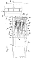
- a device 1 for cyclically processing book block 2 formed from at least one printing sheet is illustrated by adhesive binding. Furthermore, Figs. 1 and 2 a fixed to a traction means of a rotating conveyor of a perfect binder staple 3. The supplied on a conveyor belt 4 or the like.
- the device 1 in the conveying direction F book block 2 are a feeder 5 cyclically resp. passed intermittently. That is, the book block 2 following a book block 2 ', 2''are stopped on the conveyor belt 4 until the device 1 has transferred the recorded book block 2 in the bracket 3 and in the Starting position shown in FIG. 1 has returned.
- a light barrier 6 at the delivery end of the conveyor belt 4 detects the presence of a subsequent book block 2 '.
- the feed member 5 consists of several (according to FIG. 2 five) at intervals side by side transversely to the conveying direction F arranged conveying elements 7 of rotating belts 8, for which purpose two guide rollers 9, 10 are provided.
- the conveying ends of the bands 8 form a conveying plane in which a discontinued book block 2 with the front edge in the conveying direction F is fed to a stop 11.
- the position of the stop 11, which is (also) provided for lifting the stationary book block 2 is drivingly connected to a traction mechanism 12 on both sides and along the stationary arranged Zu Industries 5 on a guide assembly 13 displaceable or movable for lifting a book block 2.
- a lifting device 14 forming stop 11 is pivotable about a horizontal axis 15, so that the pending on the stop 11 book block 2 is approximately perpendicular to this.
- the fingers 16 are arranged between each two conveying elements 7 of the Zuglassorgans 5, guide rails 18 which extend between the conveying elements 7 to a free end and with the crossbar 17th of the stop 11 are connected.
- the guide rails 18 are advantageously below the on Supports 19 sliding supported conveying run of the conveying elements 7 formed conveying plane, so that a friction of the book block 2 can be avoided on the guide rails 18.
- the lifting of a book block 2 by the associated with the stop 11 guide rails 18 begins with a pivoting movement of the lifting device 14 of FIG. 1 in the clockwise direction by 90 ° (see Fig.
- the pivoting movement takes place via a toothed wheel gear 20, consisting of a toothed wheel 22 fastened to a shaft 21 connected to the stop 11 and which meshes with a toothed segment 23 which is pivotally driven.
- the drive of the toothed segment 23 is achieved by a lever gear 24 having a voltage applied to a rotating, endless control track 25 by means of roller 28 lever arm 26 and one with its free end on the one hand and the toothed segment 23 on the other hand connected handlebar 27.
- An electric motor 29 intended for driving the feed element 5 is connected to the control track 25 by a drive belt 30.
- the staple 3 of an adhesive binder which is illustrated schematically in FIGS.
- the device 1 has an immovable 31 and a movable clamping jaw 32, which are shown in the open position of the staple 3.
- the opening operation of the clip 3 is initiated by a counter to a spring force on a control cam 33 connected to the movable jaw 32 connected roller 34.
- the device 1 follows in parallel on a transfer section of the staple 3 of the perfect binder, wherein the feed member 5 does not change its position within the device 1, but the lifting device 14 raises the book block 2 and from below into the Introduces bracket 3.
- the synchronization of the device 1 with the clip 3 of the perfect binder is initiated as soon as a book block 2 is located on the feeding member 5.
- the return of the device 1 in the starting position takes place after the takeover of the book block 2 by the bracket. 3 Fig.
- a guide member 35 shows the up through the guide rails 18 on the stop 11 in a standing on the back standing position book block 2, which is guided against tilting by a guide member 35.
- the latter is adjustable due to the changing book block thickness along the fingers 16 of the stop 11.
- the guide member 35 is drivingly connected to a further traction mechanism 36, which consists of two Anlagenstoffierin 37, each with two pulleys 37, 38 and a drive wheel 39, wherein a Umlenkrollencru 37 and the drive wheel 39 of the traction mechanism 36, the same axis 15 as the gear 22 of Zahnradvorgeleges 20 have.
- the guide element 35 which forms a support wall when the book block 2 is set up, consists of a plurality of guide elements 40 distributed on the book block back length, which can be adjusted and locked together on the fingers 16 of the stop 11.
- the guide elements 40 can be extended by an ejectable slide 41, to which a pneumatically controllable pressure cylinder 42 is connected to the slider 41.
- the patent drawing gives a detailed and exemplary execution and operation of the guide 35, so that a detailed description is unnecessary.
- Fig. 3 further illustrates the position of the ready for Kochwerk GmbHüng in the bracket 3 book block 2, which is located below the open bracket 3 of the perfect binder. The lifting of the book block 2 in the lifting device 14 takes place during the parallel synchronization of the device.
- FIG. 6 shows the book block 2 clamped in the closed position 3 of the perfect binder in the processing position.
- the roller 34 of the clamp 3 has left the control cam 33 and the stop 11 can now be lowered.
- the guide elongating slide 41 of the guide elements 40 are retracted as shown in FIG. 7, so that upon pivoting back of the lifting device 14, an impact on the bracket 3 is prevented.
- the lifting device 14 has reached the starting position again and it can be a next book block 2 'taken from conveyor belt 4.
Abstract
Description
Die Erfindung betrifft eine Einrichtung zur taktweisen Verarbeitung von aus wenigstens einem Druckbogen gebildeten Buchblocks durch Klebebinden, bestehend aus einer die liegend und rückenvoran einem das Förderende eines Zuführorgans bildenden Anschlag zugeführten Buchblocks und diese in eine darüber an einem Zugmittel umlaufende Klammer eines Förderers zur Ueberführung jeweils eines Buchblocks im Gleichlauf parallel angetriebenen Hebevorrichtung.The invention relates to a device for the cyclical processing of book block formed by at least one printing sheet by adhesive bonding, consisting of a lying and back voran a conveyor end of a feed forming abutment supplied book block and this in a circulating on a traction means clamp of a conveyor for the transfer of one each Book blocks in synchronism parallel driven lifting device.
Unter der Bezeichnung Amigo Digital vertreibt die Müller Martini Marketing AG, Zofingen/Schweiz einen automatischen Klein-Klebebinder. Bei diesem werden Buchblocks hintereinander einem am Ende eines Zuführweges angeordneten Anschlag einer Hebevorrichtung zugeführt und entlang diesem in eine stehende Lage nach oben geschwenkt, von wo der Buchblock in eine offene Klammer eines umlaufenden Förderers fällt. Während diesem Vorgang bewegt sich die Hebevorrichtung im Gleichlauf mit der umlaufenden Klammer. In dieser Klammer passiert der eingespannte Buchblock die Bearbeitungsstationen eines Klebebinders.Muller Martini Marketing AG, Zofingen / Switzerland sells an automatic small perfect binder under the name Amigo Digital. In this book blocks are successively fed to a arranged at the end of a Zuführweges stop a lifting device and pivoted along this in a standing position up, from where the book block falls into an open bracket of a revolving conveyor. During this process The lifting device moves in synchronism with the rotating clamp. In this clip, the clamped book block passes the processing stations of a perfect binder.
Ein Nachteil dieser bekannten Einrichtung besteht darin, dass die Buchblöcke, nachdem sie in die stehende Lage angehoben sind, beim anschliessenden Zurückfallen in eine offene Klammer hinsichtlich ihrer Lage, insbesondere die Lage der einzelnen Druckbogen eines Buchblockes nicht kontrollierbar sind und so die Produktionsqualität und -zuverlässigkeit beeinträchtigen können.A disadvantage of this known device is that the book blocks after they are raised in the standing position, the subsequent fall back into an open bracket with respect to their position, in particular the position of the individual sheets of a book block are not controllable and so the production quality and reliability can affect.
Eine Zuführung der Buchblocks auf einer schiefen Ebene von unten nach oben, wie bekannt, ist nur über mehrere Verarbeitungstakte möglich, wozu eine längere Zuführstrecke erforderlich wäre.A feed of the book blocks on an inclined plane from bottom to top, as is known, is possible only over several processing cycles, for which a longer feed distance would be required.
Aufgabe der vorliegenden Erfindung ist es, eine Einrichtung der eingangs genannten Art zu schaffen, mit der auf einfache Weise die erwähnten Umstände bei der Buchblockübergabe in eine Klammer eines Förderers vermieden werden.Object of the present invention is to provide a device of the type mentioned above, with the easily avoided the circumstances mentioned in the book block transfer into a clamp of a conveyor.
Erfindungsgemäss wird diese Aufgabe dadurch gelöst, dass dem Zuführorgan die den Anschlag aufweisende Hebevorrichtung zugeordnet ist, durch die ein zugeführter Buchblock um eine horizontale Achse in eine stehende Lage verschwenkbar und mittels verstellbar angetriebenem Anschlag in die Klammer des Förderers überführbar ist.
Mit dieser konstruktiven Massnahme können liegend zugeführte Buchblocks gezielt und unter Vermeidung wenigstens einer Bewegung ungehindert in einen Klebebinder überführt werden.According to the invention this object is achieved in that the Zuführorgan is associated with the stop lifting device by which a supplied book block about a horizontal axis in a standing position pivotally and by means of adjustable driven stop in the clamp of the conveyor can be transferred.
With this constructive measure lying book block can be selectively transferred and avoiding at least one movement unhindered in an adhesive binder.
Ueberdies beansprucht eine solche Lösung eine geringere Bauhöhe.Moreover, such a solution claims a lower height.
Diese Einrichtung eignet sich für einen Klebebinder mit auf einer Kreisbahn oder einer ovalen Bahn umlaufenden Klammer.This device is suitable for an adhesive binder with circulating on a circular path or an oval track clamp.
Die Hebevorrichtung weist vorteilhaft einen Anschlag auf, der zur Ueberführung eines Buchblocks in eine Klammer des Förderers um eine horizontale Achse schwenkbar ist und senkrecht zur Zuführrichtung des Buchblocks förderwirksam verstellbar ist, wobei die Hebebewegung des Anschlags schon vor dem Eintreffen eines Buchblocks am Anschlag eingeleitet werden kann. Die Verstellbarkeit des Anschlages kann auch zur Einstellung des Formats des zugeführten Buchblocks verwendet werden.The lifting device advantageously has a stop which is pivotable about a horizontal axis for transferring a book block into a clamp of the conveyor and perpendicular to the feed direction of the book block is conveyively adjustable, wherein the lifting movement of the stop can be initiated before the arrival of a book block at the stop , The adjustability of the stop can also be used to adjust the format of the supplied book block.
Als eine einfache Weiterausgestaltung des erfindungsgemässen Gegenstandes erweist es sich, wenn der Anschlag an einer Führungsanordnung entlang des Zuführorgans resp. entlang einer Führungsebene der Hebevorrichtung verstellbar ist, sodass eine funktionelle Ueberlagerung der Bewegungen der Hebevorrichtung und dadurch ein Zeitgewinn entstehen kann.As a simple further development of the inventive subject matter, it turns out when the stop responds to a guide assembly along the Zuführorgans. is adjustable along a management level of the lifting device, so that a functional superposition of the movements of the lifting device and thereby a gain of time can arise.
Durch das Zusammenwirken von Zuführorgan und Hebevorrichtung weist der Anschlag vorteilhaft in Abständen über die Förderbreite des Zuführorgans versetzt abstehende Finger auf.Due to the interaction of supply member and lifting device, the stop advantageously offset at intervals over the conveying width of the Zuführorgans protruding fingers.
Vorzugsweise ist der Anschlag um eine unterhalb der Förderebene des Zuführorgans angeordnete horizontale Achse in Zuführrichtung der Buchblocks zurück schwenkbar, derart, dass die Hebevorrichtung von dem Zuführorgan aushebbar und zurückversenkbar ist.Preferably, the stop is pivotable back about a arranged below the conveying plane of the Zuführorgans horizontal axis in the feed direction of the book block, such that the lifting device of the feed member can be raised and zurückversenkbar.
Zweckdienlich sind die Finger des Anschlages an den Wurzeln zwischen jeweils zwei das Zuführorgan bildende Fördertrum umlaufender Zugmittel versenkbar angeordnet.Conveniently, the fingers of the stop at the roots between two each of the feed member forming conveyor strand rotating traction means are arranged retractable.
Mit dem Anschlag sind vorzugsweise Führungsleisten verbunden, die einen rechten Winkel mit den Fingern bilden.With the stop guide rails are preferably connected, which form a right angle with the fingers.
Die Führungsleisten sind beim Zuführen der Buchblocks vorteilhaft zwischen den umlaufenden Zugmitteln des Zuführorgans angeordnet, so dass die Buchblocks ausschliesslich von den Fördertrums der Zugmittel transportiert werden.The guide rails are advantageously arranged when feeding the book block between the circulating traction means of the Zuführorgans, so that the book blocks are transported exclusively by the conveying strand of the traction means.
Zur Verstellung des Anschlags resp. zur Ueberführung eines Buchblocks in eine Klammer eines Klebebinders ist ersterer zweckmässig mit einem Zugmittelgetriebe antriebsverbunden, durch welches der Buchblock aus einer stehenden Lage nach oben gefördert wird.To adjust the attack resp. for transferring a book block into a clamp of a perfect binder, the former is expediently drive-connected to a traction mechanism, by means of which the book block is conveyed upwards from a stationary position.
Die Buchblocks können jeweils aus der liegenden Position auf dem Zuführorgan durch ein mit dem Anschlag antriebsverbundenes Vorgelege mittels der Führungsleisten in eine auf dem Buchblockrücken stehende Lage geschwenkt werden.The book blocks can each be pivoted from the lying position on the feeder by a drive-connected with the stop countershaft by means of the guide rails in a standing on the book block back position.
Gegen das einseitige Kippen der auf dem Anschlag stehenden Buchblocks ist den die Führungsebene bildenden Führungsleisten mit Abstand ein Leitorgan zugeordnet, welches den Buchblock an der gegenüberliegenden Seite stützt und führt.Against the one-sided tilting of the book block standing on the stop, the guiding plane forming guide rails is assigned by far a guide member which supports and guides the book block on the opposite side.
Insbesondere für kleine Buchblockformate kann das Leitorgan parallel zu der durch die Führungsleisten gebildeten Führungsebene durch einen Schieber verlängert werden.In particular, for small book block formats, the guide element can be extended parallel to the guide plane formed by the guide level by a slider.
Die unterschiedlichen Buchblockdicken verlangen gegen das Kippen ein Verstellen des Abstandes zwischen der durch die Führungsleisten gebildeten Führungsebene und dem Leitorgan, wozu vorteilhaft ein Zugmittelgetriebe vorgesehen ist.The different book block thicknesses require against tilting an adjustment of the distance between the guide plane formed by the guide rail and the guide element, for which purpose a traction mechanism is advantageously provided.
Anschliessend wird die Erfindung unter Bezugnahme auf die Zeichnung, auf die bezüglich aller in der Beschreibung nicht näher erwähnten Einzelheiten verwiesen wird, anhand eines Ausführungsbeispiels erläutert. In der Zeichnung zeigen:
- Fig. 1
- eine Seitenansicht einer Ausführungsform der erfindungsgemässen Einrichtung sowie eine Klammer eines Klebebinders,
- Fig. 2
- eine Draufsicht auf die in Fig. 1 gezeigte Einrichtung,
- Fig. 3
- eine Seitenansicht der Einrichtung gemäss Fig. 1 mit verschwenkter Hebevorrichtung,
- Fig. 4
- eine Seitenansicht der Einrichtung gemäss Fig. 3 mit verlängertem Leitorgan,
- Fig. 5
- eine Seitenansicht der Einrichtung gemäss einer der Fig. 3 und 4 mit angehobenem Buchblock,
- Fig. 6
- eine Seitenansicht der Einrichtung gemäss einer der Fig. 3 bis 5 mit in die Klammer des Klebebinders überführtem Buchblock,
- Fig. 7
- eine Seitenansicht der Einrichtung gemäss einer der Fig. 3 bis 6 mit eingespanntem Buchblock bei zurückgefahrenem Anschlag und Leitorgan,
- Fig. 8
- eine Seitenansicht der Einrichtung gemäss einer der Fig. 3 bis 6 mit der sich in der Ausgangsposition befindenden Hebevorrichtung und
- Fig. 9
- einen Längsschnitt gemäss A - A in Fig. 1 durch eine die Verstellantriebe der Hebevorrichtung, des Anschlages und des Leitorgans aufweisenden gemeinsamen Antriebsachse.
- Fig. 1
- a side view of an embodiment of the inventive device and a clip of a perfect binder,
- Fig. 2
- a plan view of the device shown in Fig. 1,
- Fig. 3
- 1 is a side view of the device according to FIG. 1 with pivoted lifting device, FIG.
- Fig. 4
- a side view of the device according to FIG. 3 with extended guide member,
- Fig. 5
- 3 shows a side view of the device according to one of FIGS. 3 and 4 with the book block raised,
- Fig. 6
- 3 shows a side view of the device according to one of FIGS. 3 to 5 with the book block transferred into the clip of the adhesive binder,
- Fig. 7
- 3 is a side view of the device according to one of FIGS. 3 to 6 with clamped book block when retracted stop and guide element,
- Fig. 8
- a side view of the device according to one of Figs. 3 to 6 with the lifting device located in the starting position and
- Fig. 9
- a longitudinal section according to A - A in Fig. 1 by a the adjusting drives the lifting device, the stop and the guide member having common drive axle.
In den Fig. 1 und 2 ist eine Einrichtung 1 zur taktweisen Verarbeitung von aus wenigstens einem Druckbogen gebildeten Buchblocks 2 durch Klebebinden dargestellt. Weiterhin zeigen die Fig. 1 und 2 eine an einem Zugmittel eines umlaufenden Förderers eines Klebebinders befestigte Klammer 3. Die auf einem Förderband 4 oder dgl. der Einrichtung 1 in Förderrichtung F zugeführten Buchblocks 2 werden einem Zuführorgan 5 taktweise resp. intermittierend übergeben. D.h., die einem überführten Buchblock 2 folgenden Buchblocks 2', 2'' werden solange auf dem Förderband 4 angehalten, bis die Einrichtung 1 den aufgenommenen Buchblock 2 in die Klammer 3 überführt hat und in die Ausgangsstellung gemäss Fig. 1 zurückgekehrt ist. Eine Lichtschranke 6 am Förderende des Förderbandes 4 stellt die Anwesenheit eines nachfolgenden Buchblocks 2' fest. Das Zuführorgan 5 besteht aus mehreren (gemäss Fig. 2 fünf) in Abständen nebeneinander quer zur Förderrichtung F angeordneten Förderelementen 7 aus umlaufenden Bändern 8, wozu jeweils zwei Umlenkrollen 9, 10 vorgesehen sind. Die Fördertrums der Bänder 8 bilden eine Förderebene in der ein aufgegebener Buchblock 2 mit der in Förderrichtung F vorderen Kante einem Anschlag 11 zugeführt wird. Die Position des Anschlages 11, der (auch) zum Anheben der stehenden Buchblocks 2 vorgesehen ist, ist mit einem Zugmittelgetriebe 12 beidseits antriebsverbunden und entlang des stationär angeordneten Zuführorgans 5 an einer Führungsanordnung 13 versetzbar bzw. zum Anheben eines Buchblocks 2 verfahrbar. Daneben ist der Teil einer Hebevorrichtung 14 bildende Anschlag 11 um eine horizontale Achse 15 schwenkbar, so dass der am Anschlag 11 anstehende Buchblock 2 etwa senkrecht auf diesem steht. Hierzu weist der Anschlag 11, an dem der Buchblock 2 mit dem Rücken ansteht, mehrere über die Rückenlänge des Buchblocks 2 resp. quer zur Förderrichtung F in Abständen verteilte Finger 16 auf, die an einer mit dem Zugmittel 12 antriebsverbundenen Traverse 17 befestigt und an der Führungsanordnung 13 verschiebbar sind. Als Aufstellhilfe der Buchblocks 2 weist der um etwa 90° umlegbare Anschlag 11, dessen Finger 16 zwischen jeweils zwei Förderelementen 7 des Zuführorgans 5 angeordnet sind, Führungsleisten 18 auf, die sich zwischen den Förderelementen 7 zu einem freien Ende hin erstrecken und mit der Traverse 17 des Anschlages 11 verbunden sind. Zum Zeitpunkt der Zuführung der Buchblocks 2, also in der Ausgangsstellung der Hebevorrichtung 14, befinden sich die Führungsleisten 18 vorteilhaft unterhalb der durch die auf Auflagen 19 gleitend abgestützten Fördertrums der Förderelemente 7 gebildeten Förderebene, damit eine Reibung der Buchblocks 2 an den Führungsleisten 18 vermieden werden kann.
Das Anheben eines Buchblocks 2 durch die mit dem Anschlag 11 verbundenen Führungsleisten 18 beginnt mit einer Schwenkbewegung der Hebevorrichtung 14 gemäss Fig. 1 im Uhrzeigersinn um 90° (siehe Fig. 3), nach welcher der Buchblock 2 in einer senkrechten Lage aufrecht auf dem Anschlag 11 steht. Die Schwenkbewegung erfolgt über ein Zahnradvorgelege 20, bestehend aus einem an einer mit dem Anschlag 11 verbundenen Welle 21 befestigten Zahnrad 22, das mit einem schwenkbar angetriebenen Zahnsegment 23 kämmt. Der Antrieb des Zahnsegmentes 23 wird durch ein Hebelgetriebe 24 erzielt, das einen an einer drehenden, endlosen Steuerbahn 25 mittels Rolle 28 anliegenden Hebelarm 26 und einen mit dessen freiem Ende einerseits und dem Zahnsegment 23 andererseits verbundenen Lenker 27 aufweist.
Ein für den Antrieb des Zuführorgans 5 bestimmter Elektromotor 29 ist durch einen Antriebsriemen 30 mit der Steuerbahn 25 verbunden. Die in den Fig. 1 und 2 schematisch veranschaulichte Klammer 3 eines Klebebinders weist eine unbewegliche 31 und eine bewegliche Klemmbacke 32 auf, die in geöffneter Stellung der Klammer 3 gezeigt sind. Der Oeffnungsvorgang der Klammer 3 wird durch eine gegen eine Federkraft auf eine Steuerkulisse 33 auflaufende mit der beweglichen Klemmbacke 32 verbundene Rolle 34 eingeleitet.
Während dem Ueberführungsvorgang folgt die Einrichtung 1 auf einem Ueberführungsabschnitt parallel der Klammer 3 des Klebebinders im Gleichlauf, wobei das Zuführorgan 5 dabei seine Lage innerhalb der Einrichtung 1 nicht ändert, die Hebevorrichtung 14 jedoch den Buchblock 2 hochstellt und von unten in die Klammer 3 einführt. Der Gleichlauf der Einrichtung 1 mit der Klammer 3 des Klebebinders wird eingeleitet, sobald sich ein Buchblock 2 auf dem Zuführorgan 5 befindet. Die Rückkehr der Einrichtung 1 in die Ausgangsstellung erfolgt nach Uebernahme des Buchblocks 2 durch die Klammer 3.
Fig. 3 zeigt den durch die Führungsleisten 18 am Anschlag 11 in eine auf dem Rücken stehende Lage hochgeschwenkten Buchblock 2, der gegen Kippen durch ein Leitorgan 35 geführt ist. Letzteres ist aufgrund der sich ändernden Buchblockdicke entlang den Fingern 16 des Anschlages 11 verstellbar. Hierzu ist das Leitorgan 35 mit einem weiteren Zugmittelgetriebe 36 antriebsverbunden, das aus zwei Zugmittelelementen 37 mit jeweils zwei Umlenkrollen 37, 38 und einem Antriebsrad 39 besteht, wobei ein Umlenkrollenpaar 37 und das Antriebsrad 39 des Zugmittelgetriebes 36 die gleiche Achse 15 wie das Zahnrad 22 des Zahnradvorgeleges 20 aufweisen.
Das Leitorgan 35, das bei aufgestelltem Buchblock 2 für diesen eine Stützwand bildet, besteht aus mehreren, auf die Buch- blockrückenlänge verteilten Leitelementen 40, die gemeinsam an den Fingern 16 des Anschlages 11 verstell- und feststellbar sind. Für eine kleine Formatbreite eines Buchblocks 2 können die Leitelemente 40 durch einen ausstossbaren Schieber 41 verlängert werden, wozu ein pneumatisch steuerbarer Druckzylinder 42 mit dem Schieber 41 verbunden ist. Die Patentzeichnung vermittelt ausführlich und beispielhaft eine Ausführung und Funktionsweise des Leitorgans 35, sodass sich eine detaillierte Beschreibung erübrigt. Fig. 3 stellt weiterhin die Lage des zur Ueberführüng in die Klammer 3 bereitstehenden Buchblocks 2 dar, der sich unterhalb der offenen Klammer 3 des Klebebinders befindet. Das Anheben des Buchblocks 2 in der Hebevorrichtung 14 erfolgt während dem parallelen Gleichlauf der Einrichtung 1 -Zuführorgan 5 und Hebevorrichtung 14- und der Klammer 3 aus der Stellung gemäss Fig. 3. Befindet sich ein Buchblock 2 mit kleiner Formatbreite zwischen den Führungsleisten 18 und dem Leitorgan 35, werden (unmittelbar) vor dem Anheben des Buchblocks zur Ueberführung in die Klammer 3 die Schieber 41 der Leitelemente 40 ausgestossen, sodass der Buchblock 2 die Klammer 3 geführt erreicht (siehe Fig. 4 und 5).
Fig. 6 zeigt den in der geschlossenen Klammer 3 des Klebebinders in der Verarbeitungsposition eingespannten Buchblock 2. Die Rolle 34 der Klammer 3 hat die Steuerkulisse 33 verlassen und der Anschlag 11 kann nun abgesenkt werden.
Während dem Absenken der Finger 16 des Anschlages 11 werden die die Führung verlängernden Schieber 41 der Leitelemente 40 gemäss Fig. 7 eingezogen, damit beim Zurückschwenken der Hebevorrichtung 14 ein Auftreffen an der Klammer 3 verhindert wird.In FIGS. 1 and 2, a device 1 for cyclically processing
The lifting of a
An
During the transfer process, the device 1 follows in parallel on a transfer section of the
Fig. 3 shows the up through the guide rails 18 on the
The
FIG. 6 shows the
During the lowering of the
In Fig. 8 hat die Hebevorrichtung 14 die Ausgangsstellung wieder erreicht und es kann ein nächster Buchblock 2' von Förderband 4 übernommen werden.In Fig. 8, the lifting
Fig. 9 zeigt die für die Verstellantriebe der Hebevorrichtung 14, des Anschlags 11 und des Leitorgans 35 vorgesehene gemeinsame Achse 15, die eine in einem Gestell 43 gelagerte Welle 21 des Zahnrades 22 für die Schwenkbewegungen der Hebevorrichtung 14 bestimmten Zahnradvorgeleges 20 aufweist.
Auf der Welle 21 lagert ein weiteres Zahnrad 44, das mit dem Zugmittelgetriebe 12 zur Verstellung des Anschlages 11 resp. zur Anhebung eines auf letzterem stehenden und in die Klammer 3 zu überführenden Buchblock 2 verbunden ist, wobei die Verbindung des Zahnrades 44 mit dem Zugmittelgetriebe 12 durch eine auf der Welle 21 lagernde Hohlwelle 45 gelöst ist.
Dem zur Verstellung des Leitorgans 35 zuständigen Zugmittelgetriebe 36 ist an der Achse 15 das weitere Zahnrad 39 zugeordnet, das an einer weiteren Hohlwelle 47 festsitzt, die an der Hohlwelle 45 drehbar sitzt. Mit der Hohlwelle 45 sind Umlenkräder des für die Verstellung des Leitorgans 35 vorgesehen Zugmittelgetriebes verbunden.9 shows the
On the
The responsible for adjusting the
Claims (16)
Priority Applications (6)
| Application Number | Priority Date | Filing Date | Title |
|---|---|---|---|
| AT04405631T ATE399650T1 (en) | 2004-10-07 | 2004-10-07 | DEVICE FOR THE CYCLE PROCESSING OF BOOK BLOCKS FORMED FROM AT LEAST ONE PRINTED SHEET |
| EP04405631A EP1645434B1 (en) | 2004-10-07 | 2004-10-07 | Apparatus for the sychronised processing of a book block made of at least one printed sheet |
| DE502004007501T DE502004007501D1 (en) | 2004-10-07 | 2004-10-07 | Device for the cyclic processing of book block formed from at least one printed sheet |
| JP2005284060A JP2006103323A (en) | 2004-10-07 | 2005-09-29 | Apparatus for periodically processing book block formed of at least one sheet of printing paper with glue book-binding machine |
| US11/245,446 US7607882B2 (en) | 2004-10-07 | 2005-10-07 | Apparatus for the timed processing of book blocks for perfect binding |
| CN200510108414.7A CN1757522B (en) | 2004-10-07 | 2005-10-08 | Apparatus for circularly bonded processing of a book block made of at least one printed sheet |
Applications Claiming Priority (1)
| Application Number | Priority Date | Filing Date | Title |
|---|---|---|---|
| EP04405631A EP1645434B1 (en) | 2004-10-07 | 2004-10-07 | Apparatus for the sychronised processing of a book block made of at least one printed sheet |
Publications (2)
| Publication Number | Publication Date |
|---|---|
| EP1645434A1 true EP1645434A1 (en) | 2006-04-12 |
| EP1645434B1 EP1645434B1 (en) | 2008-07-02 |
Family
ID=34932311
Family Applications (1)
| Application Number | Title | Priority Date | Filing Date |
|---|---|---|---|
| EP04405631A Not-in-force EP1645434B1 (en) | 2004-10-07 | 2004-10-07 | Apparatus for the sychronised processing of a book block made of at least one printed sheet |
Country Status (6)
| Country | Link |
|---|---|
| US (1) | US7607882B2 (en) |
| EP (1) | EP1645434B1 (en) |
| JP (1) | JP2006103323A (en) |
| CN (1) | CN1757522B (en) |
| AT (1) | ATE399650T1 (en) |
| DE (1) | DE502004007501D1 (en) |
Cited By (5)
| Publication number | Priority date | Publication date | Assignee | Title |
|---|---|---|---|---|
| EP2292444A2 (en) | 2009-09-03 | 2011-03-09 | Müller Martini Holding AG | Device for the paced processing of a printed product with a transfer device |
| EP2803496A1 (en) * | 2013-05-17 | 2014-11-19 | Müller Martini Holding AG | Feeder for an adhesive binding machine |
| CN104443981A (en) * | 2014-10-29 | 2015-03-25 | 肇庆三向教学仪器制造有限公司 | Conveying experimental equipment capable of achieving automatic feedback |
| CN108177949A (en) * | 2017-11-28 | 2018-06-19 | 广州市永合祥自动化设备科技有限公司 | Bond production line and production method |
| US20230136370A1 (en) * | 2020-02-11 | 2023-05-04 | Heidelberger Druckmaschinen Ag | Method of moving a stack of products by use of a robot |
Families Citing this family (15)
| Publication number | Priority date | Publication date | Assignee | Title |
|---|---|---|---|---|
| US8047523B2 (en) * | 2008-11-07 | 2011-11-01 | Kabushiki Kaisha Toshiba | Sheet loading apparatus, sheet post-processing apparatus and image forming apparatus |
| ITMI20100189U1 (en) * | 2010-06-04 | 2011-12-05 | Revicart S R L | TRANSFER EQUIPMENT FOR A LINE END OF A FOLDING MACHINE. |
| CN101870406B (en) * | 2010-06-04 | 2012-05-23 | 吴仲明 | Equipment for automatically separating books, opening pages and printing anti-counterfeit and anti-channel conflict information on bound printed matters |
| US8579101B2 (en) * | 2010-12-23 | 2013-11-12 | Johnsen Machine Company Ltd. | Bag turning machine and method |
| DE102012003602A1 (en) * | 2012-02-21 | 2013-08-22 | Kolbus Gmbh & Co. Kg | Apparatus for feeding book blocks in the import channel of a Weiterverarbeitungseinrichhtung |
| EP2810904B1 (en) * | 2013-06-05 | 2016-03-09 | Müller Martini Holding AG | Feeding of loose stacks of sheets into a transport channel |
| US10093440B2 (en) * | 2014-01-21 | 2018-10-09 | R.A. Pearson Company | Vertical load case packer |
| AU2015376066B2 (en) * | 2015-01-07 | 2021-03-11 | Nilesh Dhirajlal Parmar | Sheet processing machine and method of manufacturing thereof |
| CN106494114B (en) * | 2016-12-30 | 2018-03-06 | 深圳市精密达机械有限公司 | A kind of this equipment of bookblock point |
| CN108620567B (en) * | 2018-07-17 | 2023-11-17 | 浙江省机电设计研究院有限公司 | Device and method for conveying sand boxes at fixed beats |
| JP7311887B2 (en) * | 2019-08-08 | 2023-07-20 | ホリゾン・インターナショナル株式会社 | Bookbinding equipment |
| JP6694194B1 (en) * | 2019-11-07 | 2020-05-13 | ホリゾン・インターナショナル株式会社 | Paper bundle supply device |
| DE102020103402A1 (en) | 2020-02-11 | 2021-08-12 | Heidelberger Druckmaschinen Aktiengesellschaft | Method for moving a stack of products with a robot |
| DE102020103400A1 (en) | 2020-02-11 | 2021-08-12 | Heidelberger Druckmaschinen Aktiengesellschaft | Method for moving a stack of products with a robot |
| DE102020201669A1 (en) | 2020-02-11 | 2021-08-12 | Heidelberger Druckmaschinen Aktiengesellschaft | Device for moving a stack of products with a robot |
Citations (4)
| Publication number | Priority date | Publication date | Assignee | Title |
|---|---|---|---|---|
| US3633727A (en) * | 1968-09-07 | 1972-01-11 | Walter Sigloch Grossbuchbinder | Device for feeding book pads to a trimming machine |
| DE2226455A1 (en) * | 1972-05-26 | 1973-12-13 | Smith Mfg Co | DEVICE FOR EXECUTING BOOKS FROM SINGLE-KNIFE BOOKBINDING MACHINES |
| DE3413222A1 (en) * | 1984-04-07 | 1985-10-17 | Kolbus GmbH & Co KG, 4993 Rahden | Method for transferring book blocks into the transporting means of a book-binding machine and apparatus for carrying out the method |
| EP0790139A1 (en) * | 1996-02-17 | 1997-08-20 | Horizon International Inc. | Apparatus for supplying paper to book producing machine |
Family Cites Families (28)
| Publication number | Priority date | Publication date | Assignee | Title |
|---|---|---|---|---|
| US2666926A (en) * | 1950-03-25 | 1954-01-26 | Isaacs Marcus Manly | Buckle and like mounting |
| US2865517A (en) * | 1954-10-26 | 1958-12-23 | Wm Hollingsworth Machine Co In | Inverter for printed sheets |
| US3043506A (en) * | 1960-03-07 | 1962-07-10 | James M Shackleton | Envelope construction |
| US3593913A (en) * | 1969-04-29 | 1971-07-20 | Fred C Bremer | Document carrier construction |
| US3576972A (en) * | 1969-09-12 | 1971-05-04 | Doniel J Wood | Document carrier |
| US3757736A (en) * | 1971-04-12 | 1973-09-11 | Magnamatrix Corp | Semi-automatic bookbinder |
| US3800124A (en) * | 1971-08-23 | 1974-03-26 | Saving Devices Inc Lab | Envelope for mutilated checks |
| US3908836A (en) * | 1974-05-01 | 1975-09-30 | Takashi Ikeda | Apparatus for supplying sheets to a sheet processing machine in successive stacks |
| CA1093593A (en) * | 1977-10-24 | 1981-01-13 | Masateru Tokuno | Apparatus for transporting boards |
| FR2543928B1 (en) * | 1983-04-08 | 1986-01-17 | Martin Sa | METHOD AND DEVICE FOR AUTOMATICALLY FEEDING A PLATE PRODUCTS PROCESSING MACHINE |
| US4640655A (en) * | 1985-04-12 | 1987-02-03 | Con-Vey/Keystone, Inc. | Continuous feeding apparatus |
| US4700941A (en) * | 1986-05-22 | 1987-10-20 | Thermoguard Equipment Inc. | Corrugated sheet unstacking and feeding apparatus |
| DE3713036A1 (en) * | 1987-01-21 | 1988-08-04 | Kolbus Gmbh & Co Kg | FRONT ADHESIVE DEVICE FOR ADHESIVE BINDING MACHINE |
| JP3046976B2 (en) * | 1992-05-27 | 2000-05-29 | ホリゾン・インターナショナル株式会社 | Discharge device for bookbinding machine |
| US5358372A (en) * | 1993-07-08 | 1994-10-25 | Thermoguard Equipment, Inc. | Sheet block inverter |
| US5427225A (en) * | 1993-07-21 | 1995-06-27 | Oimatsu Industries Company Limited | Sheet-like workpiece delivering apparatus |
| DE4417691C2 (en) * | 1994-05-20 | 1997-01-30 | Roland Man Druckmasch | System for preparing a stack of sheets for processing in a sheet-processing machine |
| US5594225A (en) * | 1995-06-07 | 1997-01-14 | Botvin; Arthur D. | Methods and systems for conducting financial transactions via facsimile |
| US5743374A (en) * | 1995-08-25 | 1998-04-28 | Monsees; Claude E. | Stack turner and replenisher and method |
| JP3165954B2 (en) * | 1996-02-17 | 2001-05-14 | ホリゾン・インターナショナル株式会社 | Paper feeder for bookbinding device |
| JP3484696B2 (en) * | 1996-02-17 | 2004-01-06 | ホリゾン・インターナショナル株式会社 | Connection structure between bookbinding device and paper supply device |
| JPH10217632A (en) * | 1997-02-05 | 1998-08-18 | Dainippon Printing Co Ltd | Bookbinding device |
| CA2230464C (en) * | 1997-02-28 | 2004-07-20 | Newnes Machine Ltd. | Continuous breakdown tilt hoist with overhead rotatable secondary hoist |
| US5954473A (en) * | 1997-06-23 | 1999-09-21 | Moore U.S.A., Inc. | Readily adjustable cut sheet stacker |
| US6142288A (en) * | 1997-11-06 | 2000-11-07 | Asterisk, Inc. | Fanfold sheet feeder having stack positioner |
| ITMI991140A1 (en) * | 1999-05-24 | 2000-11-24 | O M G Di G Pessina E A Perobel | CONVEYOR AND ROTATION APPARATUS OF PACKAGES OF BOOKS OR SIMILAR |
| DE19959745A1 (en) * | 1999-12-10 | 2001-06-13 | Kolbus Gmbh & Co Kg | Method for producing brochures and device for carrying out the method |
| ITMI20010137A1 (en) * | 2000-02-12 | 2002-07-25 | Kolbus Gmbh & Co Kg | PROCEDURE FOR BINDING A BLOCK OF BOOK OR BOOKLET IN A COVER AND DEVICE FOR EXECUTION OF THE PROCEDURE |
-
2004
- 2004-10-07 EP EP04405631A patent/EP1645434B1/en not_active Not-in-force
- 2004-10-07 DE DE502004007501T patent/DE502004007501D1/en active Active
- 2004-10-07 AT AT04405631T patent/ATE399650T1/en not_active IP Right Cessation
-
2005
- 2005-09-29 JP JP2005284060A patent/JP2006103323A/en not_active Ceased
- 2005-10-07 US US11/245,446 patent/US7607882B2/en not_active Expired - Fee Related
- 2005-10-08 CN CN200510108414.7A patent/CN1757522B/en not_active Expired - Fee Related
Patent Citations (4)
| Publication number | Priority date | Publication date | Assignee | Title |
|---|---|---|---|---|
| US3633727A (en) * | 1968-09-07 | 1972-01-11 | Walter Sigloch Grossbuchbinder | Device for feeding book pads to a trimming machine |
| DE2226455A1 (en) * | 1972-05-26 | 1973-12-13 | Smith Mfg Co | DEVICE FOR EXECUTING BOOKS FROM SINGLE-KNIFE BOOKBINDING MACHINES |
| DE3413222A1 (en) * | 1984-04-07 | 1985-10-17 | Kolbus GmbH & Co KG, 4993 Rahden | Method for transferring book blocks into the transporting means of a book-binding machine and apparatus for carrying out the method |
| EP0790139A1 (en) * | 1996-02-17 | 1997-08-20 | Horizon International Inc. | Apparatus for supplying paper to book producing machine |
Cited By (9)
| Publication number | Priority date | Publication date | Assignee | Title |
|---|---|---|---|---|
| EP2292444A2 (en) | 2009-09-03 | 2011-03-09 | Müller Martini Holding AG | Device for the paced processing of a printed product with a transfer device |
| US8210512B2 (en) | 2009-09-03 | 2012-07-03 | Mueller Martini Holding Ag | Arrangement for the timed processing of a printed product with the aid of a transfer device |
| EP2803496A1 (en) * | 2013-05-17 | 2014-11-19 | Müller Martini Holding AG | Feeder for an adhesive binding machine |
| CN104163054A (en) * | 2013-05-17 | 2014-11-26 | 海德堡印刷机械股份公司 | Feeder for an adhesive binding machine |
| CN104163054B (en) * | 2013-05-17 | 2017-08-18 | 米勒马丁尼控股股份公司 | Feeder for adhesive binder |
| CN104443981A (en) * | 2014-10-29 | 2015-03-25 | 肇庆三向教学仪器制造有限公司 | Conveying experimental equipment capable of achieving automatic feedback |
| CN108177949A (en) * | 2017-11-28 | 2018-06-19 | 广州市永合祥自动化设备科技有限公司 | Bond production line and production method |
| US20230136370A1 (en) * | 2020-02-11 | 2023-05-04 | Heidelberger Druckmaschinen Ag | Method of moving a stack of products by use of a robot |
| US11952232B2 (en) * | 2020-02-11 | 2024-04-09 | Heidelberger Druckmaschinen Ag | Method of moving a stack of products by use of a robot |
Also Published As
| Publication number | Publication date |
|---|---|
| CN1757522B (en) | 2012-05-30 |
| US20060076725A1 (en) | 2006-04-13 |
| US7607882B2 (en) | 2009-10-27 |
| DE502004007501D1 (en) | 2008-08-14 |
| JP2006103323A (en) | 2006-04-20 |
| ATE399650T1 (en) | 2008-07-15 |
| CN1757522A (en) | 2006-04-12 |
| EP1645434B1 (en) | 2008-07-02 |
Similar Documents
| Publication | Publication Date | Title |
|---|---|---|
| EP1645434B1 (en) | Apparatus for the sychronised processing of a book block made of at least one printed sheet | |
| DE2807295C2 (en) | ||
| EP0623542B1 (en) | Device for forming a stack of printed sheets, where these are piled on the edge | |
| DE3015509C2 (en) | Screen printing machine | |
| DE1761688B2 (en) | Transport device for flat structures occurring in a scale formation | |
| CH651525A5 (en) | DEVICE FOR BUNDLING PAPER SHEETS, e.g. PAPER MONEY. | |
| EP0932572B1 (en) | Conveyor | |
| DE2414954A1 (en) | DEVICE FOR CREATING GAPS BETWEEN THE SHEETS OF PAPER CARRIED BY A CONVEYOR | |
| DE2508745A1 (en) | Assembly station for paper sheet stacks - has vertical jaw clamps for moving finished stack to conveyor belt | |
| DE102007053490A1 (en) | Gatherer/gang stitcher for collating folded sheets to form brochure, has driving elements adjustable between inactive position and active position, and inkjet device fitted to side of gathering section | |
| DE2335358C3 (en) | Automatic machine for transporting and sewing the signatures in books | |
| EP1942009B1 (en) | Device for pressing and joint-creasing books with book supply | |
| EP3406456B1 (en) | Adhesive binder | |
| EP1419898B1 (en) | Stapler used in the collation of printed articles to form printed products | |
| DE3508236A1 (en) | EXPORT DEVICE FOR ADHESIVE BINDING MACHINES | |
| AT412966B (en) | TRANSPORT DEVICE, ESPECIALLY FOR PLATED WORKPIECES | |
| DE102009058149A1 (en) | Device for turning book blocks, books o. The like. Printed products | |
| DE2726973C2 (en) | Book block conveyor | |
| DE102008023865A1 (en) | Saddle stitcher with variable chain pitch | |
| CH672761A5 (en) | ||
| DE3100866C2 (en) | ||
| DE2220567A1 (en) | METHOD AND DEVICE FOR BOOKBINDING | |
| DE2920667A1 (en) | METHOD AND DEVICE FOR STACKING SQUARE PRODUCTS, ESPECIALLY SQUARE PRINT PRODUCTS, MAGAZINES OR THE LIKE. | |
| EP1588861B1 (en) | Process and device for applying an at least nearly flat supplemental product on a lateral surface of a signature | |
| DE3216834C2 (en) | Device for stacking thin, large-area blanks with clean edges |
Legal Events
| Date | Code | Title | Description |
|---|---|---|---|
| PUAI | Public reference made under article 153(3) epc to a published international application that has entered the european phase |
Free format text: ORIGINAL CODE: 0009012 |
|
| AK | Designated contracting states |
Kind code of ref document: A1 Designated state(s): AT BE BG CH CY CZ DE DK EE ES FI FR GB GR HU IE IT LI LU MC NL PL PT RO SE SI SK TR |
|
| AX | Request for extension of the european patent |
Extension state: AL HR LT LV MK |
|
| 17P | Request for examination filed |
Effective date: 20060810 |
|
| AKX | Designation fees paid |
Designated state(s): AT BE BG CH CY CZ DE DK EE ES FI FR GB GR HU IE IT LI LU MC NL PL PT RO SE SI SK TR |
|
| 17Q | First examination report despatched |
Effective date: 20070126 |
|
| GRAP | Despatch of communication of intention to grant a patent |
Free format text: ORIGINAL CODE: EPIDOSNIGR1 |
|
| GRAS | Grant fee paid |
Free format text: ORIGINAL CODE: EPIDOSNIGR3 |
|
| GRAA | (expected) grant |
Free format text: ORIGINAL CODE: 0009210 |
|
| AK | Designated contracting states |
Kind code of ref document: B1 Designated state(s): AT BE BG CH CY CZ DE DK EE ES FI FR GB GR HU IE IT LI LU MC NL PL PT RO SE SI SK TR |
|
| REG | Reference to a national code |
Ref country code: GB Ref legal event code: FG4D Free format text: NOT ENGLISH |
|
| REG | Reference to a national code |
Ref country code: CH Ref legal event code: EP |
|
| REF | Corresponds to: |
Ref document number: 502004007501 Country of ref document: DE Date of ref document: 20080814 Kind code of ref document: P |
|
| REG | Reference to a national code |
Ref country code: IE Ref legal event code: FG4D Free format text: LANGUAGE OF EP DOCUMENT: GERMAN |
|
| PG25 | Lapsed in a contracting state [announced via postgrant information from national office to epo] |
Ref country code: SI Free format text: LAPSE BECAUSE OF FAILURE TO SUBMIT A TRANSLATION OF THE DESCRIPTION OR TO PAY THE FEE WITHIN THE PRESCRIBED TIME-LIMIT Effective date: 20080702 |
|
| PG25 | Lapsed in a contracting state [announced via postgrant information from national office to epo] |
Ref country code: NL Free format text: LAPSE BECAUSE OF FAILURE TO SUBMIT A TRANSLATION OF THE DESCRIPTION OR TO PAY THE FEE WITHIN THE PRESCRIBED TIME-LIMIT Effective date: 20080702 |
|
| NLV1 | Nl: lapsed or annulled due to failure to fulfill the requirements of art. 29p and 29m of the patents act | ||
| PG25 | Lapsed in a contracting state [announced via postgrant information from national office to epo] |
Ref country code: PT Free format text: LAPSE BECAUSE OF FAILURE TO SUBMIT A TRANSLATION OF THE DESCRIPTION OR TO PAY THE FEE WITHIN THE PRESCRIBED TIME-LIMIT Effective date: 20081202 Ref country code: ES Free format text: LAPSE BECAUSE OF FAILURE TO SUBMIT A TRANSLATION OF THE DESCRIPTION OR TO PAY THE FEE WITHIN THE PRESCRIBED TIME-LIMIT Effective date: 20081013 |
|
| REG | Reference to a national code |
Ref country code: IE Ref legal event code: FD4D |
|
| PG25 | Lapsed in a contracting state [announced via postgrant information from national office to epo] |
Ref country code: BG Free format text: LAPSE BECAUSE OF FAILURE TO SUBMIT A TRANSLATION OF THE DESCRIPTION OR TO PAY THE FEE WITHIN THE PRESCRIBED TIME-LIMIT Effective date: 20081002 Ref country code: FI Free format text: LAPSE BECAUSE OF FAILURE TO SUBMIT A TRANSLATION OF THE DESCRIPTION OR TO PAY THE FEE WITHIN THE PRESCRIBED TIME-LIMIT Effective date: 20080702 |
|
| PG25 | Lapsed in a contracting state [announced via postgrant information from national office to epo] |
Ref country code: IE Free format text: LAPSE BECAUSE OF FAILURE TO SUBMIT A TRANSLATION OF THE DESCRIPTION OR TO PAY THE FEE WITHIN THE PRESCRIBED TIME-LIMIT Effective date: 20080702 Ref country code: EE Free format text: LAPSE BECAUSE OF FAILURE TO SUBMIT A TRANSLATION OF THE DESCRIPTION OR TO PAY THE FEE WITHIN THE PRESCRIBED TIME-LIMIT Effective date: 20080702 Ref country code: DK Free format text: LAPSE BECAUSE OF FAILURE TO SUBMIT A TRANSLATION OF THE DESCRIPTION OR TO PAY THE FEE WITHIN THE PRESCRIBED TIME-LIMIT Effective date: 20080702 |
|
| PLBE | No opposition filed within time limit |
Free format text: ORIGINAL CODE: 0009261 |
|
| STAA | Information on the status of an ep patent application or granted ep patent |
Free format text: STATUS: NO OPPOSITION FILED WITHIN TIME LIMIT |
|
| PG25 | Lapsed in a contracting state [announced via postgrant information from national office to epo] |
Ref country code: MC Free format text: LAPSE BECAUSE OF NON-PAYMENT OF DUE FEES Effective date: 20081031 Ref country code: RO Free format text: LAPSE BECAUSE OF FAILURE TO SUBMIT A TRANSLATION OF THE DESCRIPTION OR TO PAY THE FEE WITHIN THE PRESCRIBED TIME-LIMIT Effective date: 20080702 Ref country code: SK Free format text: LAPSE BECAUSE OF FAILURE TO SUBMIT A TRANSLATION OF THE DESCRIPTION OR TO PAY THE FEE WITHIN THE PRESCRIBED TIME-LIMIT Effective date: 20080702 Ref country code: CZ Free format text: LAPSE BECAUSE OF FAILURE TO SUBMIT A TRANSLATION OF THE DESCRIPTION OR TO PAY THE FEE WITHIN THE PRESCRIBED TIME-LIMIT Effective date: 20080702 |
|
| 26N | No opposition filed |
Effective date: 20090403 |
|
| PG25 | Lapsed in a contracting state [announced via postgrant information from national office to epo] |
Ref country code: AT Free format text: LAPSE BECAUSE OF NON-PAYMENT OF DUE FEES Effective date: 20081007 Ref country code: SE Free format text: LAPSE BECAUSE OF FAILURE TO SUBMIT A TRANSLATION OF THE DESCRIPTION OR TO PAY THE FEE WITHIN THE PRESCRIBED TIME-LIMIT Effective date: 20081002 |
|
| PG25 | Lapsed in a contracting state [announced via postgrant information from national office to epo] |
Ref country code: PL Free format text: LAPSE BECAUSE OF FAILURE TO SUBMIT A TRANSLATION OF THE DESCRIPTION OR TO PAY THE FEE WITHIN THE PRESCRIBED TIME-LIMIT Effective date: 20080702 |
|
| PG25 | Lapsed in a contracting state [announced via postgrant information from national office to epo] |
Ref country code: LU Free format text: LAPSE BECAUSE OF NON-PAYMENT OF DUE FEES Effective date: 20081007 Ref country code: HU Free format text: LAPSE BECAUSE OF FAILURE TO SUBMIT A TRANSLATION OF THE DESCRIPTION OR TO PAY THE FEE WITHIN THE PRESCRIBED TIME-LIMIT Effective date: 20090103 Ref country code: CY Free format text: LAPSE BECAUSE OF FAILURE TO SUBMIT A TRANSLATION OF THE DESCRIPTION OR TO PAY THE FEE WITHIN THE PRESCRIBED TIME-LIMIT Effective date: 20080702 |
|
| PG25 | Lapsed in a contracting state [announced via postgrant information from national office to epo] |
Ref country code: TR Free format text: LAPSE BECAUSE OF FAILURE TO SUBMIT A TRANSLATION OF THE DESCRIPTION OR TO PAY THE FEE WITHIN THE PRESCRIBED TIME-LIMIT Effective date: 20080702 |
|
| PG25 | Lapsed in a contracting state [announced via postgrant information from national office to epo] |
Ref country code: GR Free format text: LAPSE BECAUSE OF FAILURE TO SUBMIT A TRANSLATION OF THE DESCRIPTION OR TO PAY THE FEE WITHIN THE PRESCRIBED TIME-LIMIT Effective date: 20081003 |
|
| REG | Reference to a national code |
Ref country code: FR Ref legal event code: PLFP Year of fee payment: 12 |
|
| PGFP | Annual fee paid to national office [announced via postgrant information from national office to epo] |
Ref country code: GB Payment date: 20151022 Year of fee payment: 12 |
|
| PGFP | Annual fee paid to national office [announced via postgrant information from national office to epo] |
Ref country code: BE Payment date: 20151022 Year of fee payment: 12 Ref country code: FR Payment date: 20151022 Year of fee payment: 12 |
|
| PG25 | Lapsed in a contracting state [announced via postgrant information from national office to epo] |
Ref country code: BE Free format text: LAPSE BECAUSE OF NON-PAYMENT OF DUE FEES Effective date: 20161031 |
|
| GBPC | Gb: european patent ceased through non-payment of renewal fee |
Effective date: 20161007 |
|
| REG | Reference to a national code |
Ref country code: FR Ref legal event code: ST Effective date: 20170630 |
|
| PG25 | Lapsed in a contracting state [announced via postgrant information from national office to epo] |
Ref country code: GB Free format text: LAPSE BECAUSE OF NON-PAYMENT OF DUE FEES Effective date: 20161007 Ref country code: FR Free format text: LAPSE BECAUSE OF NON-PAYMENT OF DUE FEES Effective date: 20161102 |
|
| REG | Reference to a national code |
Ref country code: BE Ref legal event code: MM Effective date: 20161031 |
|
| PGFP | Annual fee paid to national office [announced via postgrant information from national office to epo] |
Ref country code: DE Payment date: 20181015 Year of fee payment: 15 |
|
| PGFP | Annual fee paid to national office [announced via postgrant information from national office to epo] |
Ref country code: IT Payment date: 20181031 Year of fee payment: 15 |
|
| PGFP | Annual fee paid to national office [announced via postgrant information from national office to epo] |
Ref country code: CH Payment date: 20190122 Year of fee payment: 15 |
|
| REG | Reference to a national code |
Ref country code: DE Ref legal event code: R119 Ref document number: 502004007501 Country of ref document: DE |
|
| REG | Reference to a national code |
Ref country code: CH Ref legal event code: PL |
|
| PG25 | Lapsed in a contracting state [announced via postgrant information from national office to epo] |
Ref country code: DE Free format text: LAPSE BECAUSE OF NON-PAYMENT OF DUE FEES Effective date: 20200501 Ref country code: CH Free format text: LAPSE BECAUSE OF NON-PAYMENT OF DUE FEES Effective date: 20191031 Ref country code: LI Free format text: LAPSE BECAUSE OF NON-PAYMENT OF DUE FEES Effective date: 20191031 |
|
| PG25 | Lapsed in a contracting state [announced via postgrant information from national office to epo] |
Ref country code: IT Free format text: LAPSE BECAUSE OF NON-PAYMENT OF DUE FEES Effective date: 20191007 |