EP1644588B1 - Un système dente pour un engin de terrassement - Google Patents
Un système dente pour un engin de terrassement Download PDFInfo
- Publication number
- EP1644588B1 EP1644588B1 EP04749111A EP04749111A EP1644588B1 EP 1644588 B1 EP1644588 B1 EP 1644588B1 EP 04749111 A EP04749111 A EP 04749111A EP 04749111 A EP04749111 A EP 04749111A EP 1644588 B1 EP1644588 B1 EP 1644588B1
- Authority
- EP
- European Patent Office
- Prior art keywords
- tooth
- holder
- accordance
- essentially
- tooth portion
- Prior art date
- Legal status (The legal status is an assumption and is not a legal conclusion. Google has not performed a legal analysis and makes no representation as to the accuracy of the status listed.)
- Active
Links
- 230000003116 impacting effect Effects 0.000 claims description 13
- 238000010521 absorption reaction Methods 0.000 claims description 8
- 238000010008 shearing Methods 0.000 claims description 8
- 230000007246 mechanism Effects 0.000 claims description 6
- 239000002184 metal Substances 0.000 claims description 6
- 230000003993 interaction Effects 0.000 claims description 4
- 239000000463 material Substances 0.000 claims description 4
- 210000000078 claw Anatomy 0.000 claims description 3
- 230000002787 reinforcement Effects 0.000 claims description 2
- 230000000916 dilatatory effect Effects 0.000 claims 1
- 238000013461 design Methods 0.000 description 9
- 238000012986 modification Methods 0.000 description 8
- 230000004048 modification Effects 0.000 description 8
- 230000008901 benefit Effects 0.000 description 7
- 239000011435 rock Substances 0.000 description 7
- 230000000694 effects Effects 0.000 description 5
- 238000004140 cleaning Methods 0.000 description 4
- 238000012423 maintenance Methods 0.000 description 4
- 238000003780 insertion Methods 0.000 description 3
- 230000037431 insertion Effects 0.000 description 3
- 230000002452 interceptive effect Effects 0.000 description 3
- 230000001154 acute effect Effects 0.000 description 2
- 238000006243 chemical reaction Methods 0.000 description 2
- 230000001419 dependent effect Effects 0.000 description 2
- 230000010339 dilation Effects 0.000 description 2
- 238000009434 installation Methods 0.000 description 2
- 230000008439 repair process Effects 0.000 description 2
- 229910000831 Steel Inorganic materials 0.000 description 1
- 230000035508 accumulation Effects 0.000 description 1
- 238000009825 accumulation Methods 0.000 description 1
- 230000006978 adaptation Effects 0.000 description 1
- 238000009412 basement excavation Methods 0.000 description 1
- 230000008859 change Effects 0.000 description 1
- 238000011161 development Methods 0.000 description 1
- 230000003670 easy-to-clean Effects 0.000 description 1
- 230000006872 improvement Effects 0.000 description 1
- 230000009467 reduction Effects 0.000 description 1
- 238000010079 rubber tapping Methods 0.000 description 1
- 239000010959 steel Substances 0.000 description 1
Images


Classifications
-
- E—FIXED CONSTRUCTIONS
- E02—HYDRAULIC ENGINEERING; FOUNDATIONS; SOIL SHIFTING
- E02F—DREDGING; SOIL-SHIFTING
- E02F9/00—Component parts of dredgers or soil-shifting machines, not restricted to one of the kinds covered by groups E02F3/00 - E02F7/00
- E02F9/28—Small metalwork for digging elements, e.g. teeth scraper bits
- E02F9/2808—Teeth
- E02F9/2816—Mountings therefor
- E02F9/2825—Mountings therefor using adapters
-
- E—FIXED CONSTRUCTIONS
- E02—HYDRAULIC ENGINEERING; FOUNDATIONS; SOIL SHIFTING
- E02F—DREDGING; SOIL-SHIFTING
- E02F3/00—Dredgers; Soil-shifting machines
- E02F3/04—Dredgers; Soil-shifting machines mechanically-driven
- E02F3/28—Dredgers; Soil-shifting machines mechanically-driven with digging tools mounted on a dipper- or bucket-arm, i.e. there is either one arm or a pair of arms, e.g. dippers, buckets
- E02F3/36—Component parts
-
- E—FIXED CONSTRUCTIONS
- E02—HYDRAULIC ENGINEERING; FOUNDATIONS; SOIL SHIFTING
- E02F—DREDGING; SOIL-SHIFTING
- E02F5/00—Dredgers or soil-shifting machines for special purposes
-
- E—FIXED CONSTRUCTIONS
- E02—HYDRAULIC ENGINEERING; FOUNDATIONS; SOIL SHIFTING
- E02F—DREDGING; SOIL-SHIFTING
- E02F9/00—Component parts of dredgers or soil-shifting machines, not restricted to one of the kinds covered by groups E02F3/00 - E02F7/00
-
- E—FIXED CONSTRUCTIONS
- E02—HYDRAULIC ENGINEERING; FOUNDATIONS; SOIL SHIFTING
- E02F—DREDGING; SOIL-SHIFTING
- E02F9/00—Component parts of dredgers or soil-shifting machines, not restricted to one of the kinds covered by groups E02F3/00 - E02F7/00
- E02F9/28—Small metalwork for digging elements, e.g. teeth scraper bits
- E02F9/2808—Teeth
- E02F9/2858—Teeth characterised by shape
-
- E—FIXED CONSTRUCTIONS
- E02—HYDRAULIC ENGINEERING; FOUNDATIONS; SOIL SHIFTING
- E02F—DREDGING; SOIL-SHIFTING
- E02F9/00—Component parts of dredgers or soil-shifting machines, not restricted to one of the kinds covered by groups E02F3/00 - E02F7/00
- E02F9/28—Small metalwork for digging elements, e.g. teeth scraper bits
- E02F9/2866—Small metalwork for digging elements, e.g. teeth scraper bits for rotating digging elements
Definitions
- the present invention relates to a tooth system for a tool for earth moving machinery, which tooth system is of the type comprising a holder located on the tool and a front tooth portion that is detachably arranged on and in relation to the holder, which tooth portion is in the form of an exchangeable wear and/or replacement part intended for the actual earth moving, which tooth portion comprises a rear leg and the holder comprises a cavity designed to receive the leg in interaction with the tooth portion and thereby achieve a unified joint for assimilation of occurings loads, F s , F c , F p , via a predetermined connection geometry comprising special, opposite, mutually interacting contact surfaces and, at least initially, clearance surfaces that are arranged along the tooth portion and holder.
- An example of such tools and exchangeable wears and/or replacement part is, here, especially comprised by a dredging tool's rotating bore bit, also called a cutter head, with its replaceable wear teeth.
- these tooth systems can also be used for other types of earth moving machinery, such as the bucket to a digger, etc.
- said wear teeth are arranged at a given distance from each other, generally helical, elongated along blades protruding from a central body attached to a central, rotating hub.
- the blades suitably extend in a helical line from the hub at the forward end of the body and rearward in the tool's feed direction to the rear end of the rotating body comprising a back ring, holding the blades together, where also a suction device is arranged for removal of the loosened earthen mass through the interspace between the blades.
- Such tooth systems usually comprise two main connection parts in the form of a "female” and a “male” part that together form a full, assembled “tooth” in a series of adjacently arranged teeth along, for example, the bore bit's blades or the bucket's cutting edge.
- a "tooth” thus, comprises a forward wear-part in the form of a replaceable tooth portion with a (cutting) point and comprising a rear leg for mounting in a specially-designed groove at a rear, stationary holder, which suitably is firmly fixed to, for example, the bore bit.
- the connection parts also comprise a connection system common to the parts and with a detachable locking mechanism.
- Every such connection system has a distinctively characteristic geometry, comprising the surfaces and the form of the legs and grooves named above, in order to thereby attempt to have the wear-part of each "tooth" held effectively and safely in place in a function-sufficient manner that embodies minimal wear to the wear-part until, due to inevitable wear, the wear-part must be replaced.
- Such commercial tooth systems are designed to absorb loads (F) from the use of the tool through specially designed and mutually interactive contact zones, which are arranged along the joint between the connection parts defined by the leg and groove.
- Each contact zone comprises at least two mutually opposing and interacting contact surfaces arranged one on each connection part and arranged at a given angle to the line of axial symmetry Y of said joint.
- every active load (F) thus, comprises, see Figure 18 , in part a shearing force component, F c that acts essentially from the front parallel to the work surface and axially placed in relation to the said joint, in part a normal force component F s that acts essentially from above, perpendicular to the work surface and in part a transverse force component F p that acts from the side, essentially parallel to the work surface and more perpendicular in relation to said tooth part's protrusion beyond the connection parts' common joint.
- the new concept for a tooth system comprises a number of characteristics, which characteristics alone or in combination are unique in comparison with the presently available tooth systems and which characteristics afford advantageous solutions to a number of problems that can arise with known tooth systems.
- a consequent problem is that the conventional tooth systems that have all too wide a degree of play between the tooth and holder develop problems with "hammering", that is, said parts are powerfully impacted against one another during the use of the tool. This hammering causes considerable increase in wear. Those tooth systems that instead have all too narrow a degree of play, that is have a too small gap between the tooth and holder, develop the problem of the tooth becoming difficult to remove from the holder.
- Tooth systems designed for earth moving encounter their greatest, and thus, as regards the tooth system design, most often the gravest loads when breaking hard rock. This is due to the very large normal loads F s that impact essentially perpendicularly to the rock, as such occurs in the course of breaking rock.
- the known tooth systems, by prior art thus usually obtain disadvantageous wear damage along the joint between component connection parts of the tooth system, as these lack the required capacity to withstand such F s loads.
- Conventional tooth systems comprise a locking system that is difficult to improve upon in the confined space available between the tooth and holder at the location of the locking device being used and these tooth system do not allow separate types of locking systems and/or modifications to the locking system itself without the tooth's and/or holder's joint first being adapted to the given locking system and/or its modifications.
- leg-type tooth system can be had from the American Patent document US-A-4 642 920 and the German document DE-2 153 964 , which describe two tooth systems, each with a locking system comprising a rear, pretensioned locking mechanism.
- the strap is also subjected to all the load dynamics since it is always caught between the contact surfaces of the holder and the tooth leg when in operation.
- the tooth system described by US-3 349 508 has, in practice, only one participating contact zone for absorption, metal against metal, of the torsional forces about the Y axis since the vertical back is, preferably, without contact surfaces, e.g. it is non-contacting, and one of the two horizontal "arms" in the cross section presses against the elastic strap. In practice, essentially all wear will therefore occur at the contact zone of the first arm, where metal meets metal.
- An important object of the present invention is to achieve a new and improved tooth system for the tool for an earth removal machine, which tooth system essentially reduces or wholly eliminates the wear between the different connection parts caused by hammering and/or caused by too large surface loads on the tooth system's joint between the holder and tooth point.
- Another object of the present invention is to achieve a new and improved tooth system, which tooth system essentially reduces or wholly eliminates the problem with disadvantageously large wear damage along the joint between the tooth system's component connection parts due to the very large loads arising during, e.g., the breaking of hard rock mass.
- Yet another object of the present invention is to achieve a leg-type tooth system, which is easy to clean of dirt and earth removal residue that accumulate between the holder and the tooth portion and along the joint's contact and clearing surface(s), and further with a holder that can be easily repaired at its back side.
- the new and improved tooth system is also designed to essentially reduce and simplify the earlier, often complicated maintenance caused by the wear and the plastic deformation along the known tooth system's inner joint due to the impacting surface forces between the interactive parts.
- the new and improved tooth system also affords a possibility to increase the strength for the same due to a change in the connection geometry.
- tooth system comprises an improved locking system that allows different types of locking systems and/or modifications to the locking system to be used without essentially adapting the tooth portion's and/or holder's connection system to the given locking system and/or modifications thereof; that given locking devices can be assembled and removed in a simpler more effective manner and without any essential safety hazards arising therefrom; and that the locking system retains the capacity to maintain a fixity and the cohesive force of the connection parts, as the locking system wear increases and the above said hammering essentially is reduced or wholly eliminated.
- an improved tooth system distinguished by the tooth leg and holder cavity, along at least a front part of said joint, to have a multi-armed cruciform cross section comprising at least four projection arms and at least four grooves each that interact with each projecting arm.
- the joint and pretensioning thus, ensure that the tooth portion shall always be positioned in a predetermined position in relation to the holder and, thus, also in relation to the given tool and work surface during the entire life cycle of the tooth system.
- the multi-armed, x-shaped, joint unifies a high degree of strength with a large contact area.
- the contact area is also advantageously large, while the contact area can be advantageously less at the rear end of the joint, that is, the end of the leg, where the loads are less.
- the new tooth system combines advantages from the tooth systems known by prior art as described above.
- the part of the tooth system connection parts forming the female part, that is, the holder, that receives the other part inside itself displays a, preferably somewhat internally convergent, x-shaped front side and front part, that is, the joint surfaces in the cross-vertical plane (XZ) between the interacting sides of the tooth portion and holder, facing one another, including the corresponding surfaces along the front part of the dovetail groove and the front part of the tooth portion's leg, being multi-armed with at least four arms, cruciform or x-shaped, with a notch or dovetail groove that is internally convergent towards its back end.
- XZ cross-vertical plane
- This, cruciform and preferably somewhat convergent dovetail groove affords a play-free fixity and prevents faulty alignment since the tooth portion, that is, the male part, upon use, is pressed into the female part with increased contact along the contact surfaces along the joint between the two parts.
- the cruciform design thus, ensure that the tooth portion shall always be aligned in a predetermined position in relation to the holder and, thus, also in relation to the given tool and work surface during the entire life cycle of the tooth system. This is an especially important characteristic used with advantage by the tooth system of a dredger cutter since the dredger cutter is one of the tools which has the highest requirements for how the teeth are arranged.
- Cruciform or star-shaped etc. projection arms also afford a considerable improvement of the durability, rigidity and strength of the tooth system.
- a lesser degree of play is, at least initially, arranged on the one hand, between the vertical sides of the leg and the accordant vertical sides of the dovetail groove, at the bottom of the groove, that is, at the lower corners of the cross section (T2) and, on the other hand, the vertical sides of the spine peak and the dovetail groove's accordant vertical sides at its neck and also between the lower side of the leg and the dovetail groove's accordant bottom; but at the said play, the loads are also significally lower.
- the multi-arm form at the front of the holder also affords the great advantage of having, after only inserting the male part a minimal distance into the female part, all relevant loads, including all torques, absorbed by a very large contact area compared with what is known by prior art, which is why the surface load becomes very small and wear is consequently minimal.
- the tooth portion can also be very easily removed from the dovetail groove because the interacting parts do not grind against one another since the surface load and deformation are so low. With equivalent loads in combination with a convergent joint, a plastic deformation will presently occur between the groove and the leg that, more or less, "molds" together the parts by means of the plastic deformation.
- the present tooth system design uses the lever principle in an optimal manner.
- the new design has a joint between the holder and the tooth portion in the form of a rearwardly and upwardly open notch along the top side, preferably an open dovetail groove, which makes possible simple cleaning of the joint. It is actually sufficient to install a new tooth portion in order for cleaning to be done, because the installation of the tooth portion itself causes possible accumulations of dirt to be pushed in front of the tooth part and out through the notch's outer, rear end at the rear of the holder.
- a further advantage with the present tooth system is that it allows, to a greater extent, the use of many different types of locking systems and/or modifications to the locking system itself, without the common joint of the tooth portion and/or holder having to be significantly adapted to the given locking system and/or modifications thereto, e.g., due to a cross-going aperture for the locking device, pervading both connection parts, comprising two consecutively coaxial apertures.
- these apertures are displaced in relation to one another so that the locking mechanism can be cut off, whereupon the tooth falls out.
- a new tooth portion can no longer be installed because the new locking device aperture in the new tooth portion no longer fits the displaced locking device aperture of the worn holder.
- the locking device of the locking system can also be removed and installed by means of some standard tools, suitably an air or electrically powered wrench, without damage hazards arising therefrom.
- the present tooth system's possible locking systems that comprise an elastic body whereby the locking systems obtain the same pretensioning capacity each time a new tooth portion is installed despite the holder being worn.
- connection geometry between the tooth portion and holder of the present tooth system is equipped with an protruding part, below referred to as heel or torque heel, with a definite external geometry and a corresponding depression to interact with the heel, in order to absorb the laterally impacting transverse forces (F p ), see Figure 18 , that essentially impact parallel to the working surface but perpendicular to the axial symmetry axis of the tooth point.
- F p laterally impacting transverse forces
- the heel is arranged at the tooth portions underside and the depression at the bottom of the notch/dovetail groove.
- Said heel and depression are preferably arranged lengthwise at a position in the notch/dovetail groove that corresponds, after installation of the leg, to the optimal position for the tooth system's function with regard to the loads and torques that can conceivably arise during the use of the tool.
- the torques resulting from transverse forces (F p ), around the joint's Y axis, along the notch/dovetail groove are mainly absorbed by the horizontal contact surfaces along the tooth portion's wings that are inserted in the aforementioned, namely cruciform, front side, that is, the essentially horizontal joint surfaces between the interacting, mutually opposed sides of the tooth portion and holder in said multi-armed part.
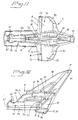
- FIG. 1 With reference to Figures 1 and 2 , there is schematically shown a tooth system 1 intended for a tool 2 for an earth moving machine 3 for the loosening and breaking of more or less hard earth and rock mass from a working surface (W), see Figure 17 , whereupon these masses can be removed in a suitable manner.
- the present invention 1 is of the type that comprises a holder 4 arranged at the tool 2 and a frontal tooth portion 5 in the form of a replaceable wear and/or replacement part intended for the earth moving itself, which tooth portion 5 is removeably arranged in relation to and at the holder 4.
- the tooth system 2 thus, comprises two main connection parts in the form of a "female part” 4 and a "male part” 5 that together form a unified and assembled "tooth".
- the holder 4 forms, preferably though not necessarily, the female part 4 of the present invention.
- Examples of an earth moving machine 3, tool 2 and wear and/or replacement parts 5 suitable for a tooth system 1 in accordance with the invention are here embodied by the rotating bore bit 2 of a dredger cutter 3 with its replaceable wear teeth 5.
- the tooth system 1 may of course also be used at other types of tools 2 of earth moving machines 3 as at the bucket of an excavator.
- said wear teeth 5 are arranged in a predetermined distance from one another, along more or less helically extending blades 6, see Figure 25 .
- the blades 6 protrude from a rotational central hub 7 and backwards in the tool's 2 direction of feed to a uniting back ring 8 forming a rotation body 9.
- a suction device 11 see Figure 2 , arranged for the removal of loosened earthen masses through an intermediary area or trough 12, see Figure 25 , between the helically shaped blades 6.
- the tooth portion 5 comprises a back leg 13 for assembly into a fitted cavity 14 at the holder 4 that is suitably fastened to the tool 2, e.g., with a weld joint or screw fastener.
- the cavity 14 is designed so that while interacting with the tooth portion 5 it receives the expended tooth leg 13, inclusive of those surfaces (B) of the tooth portion 5 that are facing theretoward and that, after assembly of the tooth portion 5 at the holder 4, during contact with the front (A) of the holder 4 is situated within an imagined vertical plane (XZ) situated directly in front of the forward most parts of the holder 4, see Figure 5 , and thereby achieve a common joint for the absorption of all loads F c , F p , F s arising through a predetermined connection geometry, essentially comprising the form of said leg 13 and cavity 14, comprising special opposed, internally and interacting contact surfaces 15 and, at least initially, clearance surfaces 16 arranged along the surfaces of the leg 6 and the cavity 14.
- at least initially it is, here, meant that these clearance surfaces 16 can be reformed into contact surfaces after some degree of inevitable wear.
- the contact surfaces 15 form a mainly blunt recess to said vertical plane (XZ), where the majority of the contact surfaces 15 at the forward part (C) of the joint, that is, comprising the front side (A) of the holder 4 and the back surfaces (B) of the tooth portion 5 that faces the holder 4, are arranged almost perpendicular to the longitudinal symmetry axis Y, that is, essentially in or parallel to the cross vertical plane (XZ).
- This forward part (C) generally absorbs all or at least the essential majority of all loads and torques that arise and as this stop zone (C) is considerably larger than those used by tooth systems known by prior art a powerful reduction of the load to surface ratio is achieved, which powerfully reduces wear, the risk of deformation, breakage and considerably extends the service life.
- the contact surfaces 15 along the back part (D) of the joint between the connection parts 4, 5, see Figures 3, 4 , 11 , and 27 are suitably arranged in a considerably more acute angle ⁇ , depicted in the shown embodiment as being less than 10°, to the axial symmetry axis Y or parallel thereto, that is, essentially in the joining direction of the connection parts 4, 5 along the joint, which is why any possible remaining load here, although after long use, is still significantly lower than that at the front part (C) of the joint and absorbed by friction forces due to the wedging effect between these contact surfaces, that is friction surfaces 15', see Figures 4 , 5 and 27 .
- the effect of transverse forces and torques on the design will be described in more detail below.
- a preferred embodiment of the notch 14 is shown seen from the back side 17 of the holder 4, from the front side (A) and from the top side 18.
- the notch 14 can be divided into a back 19, middle 20 and front 21 part(s).
- the lengthwise side walls 22 and the bottom 23 are essentially perpendicularly arranged, which is why the upward and rearward open cavity 14 becomes box-shaped, that is, the cross section within this part 19 is essentially U-shaped.
- the cross section (T2) is essentially designed as a rounded triangle where the blunt side 23' of the triangle is turned downward.
- the lengthwise, essentially vertical side walls 22, which are corresponded by the tooth portion's 5 sides, named H1 and H2, see Figure 19 , are, preferably, parallel or somewhat convergent while the bottom 23 is essentially perpendicular, that is, horizontally arranged theretoward.
- These lengthwise, essentially vertical side walls 22 shall preferably be clearance surfaces, see especially Figure 27 , while the upward continuation of the side walls 22 towards the upper, outer neck 24 of said notch 14 is formed by inwardly angled lengthwise sides 25 intended to form contact surfaces 15 together with the tooth leg 13 (see D1 and D2).
- the lengthwise side walls 26 of the notch neck 24 within the middle 20 and the front part 21 of the upper part of the notch 14, see Figures 7 and 9 extends symmetrically forward to the front side (A) of the holder 4 from an initial parallel portion 27.
- a lesser degree of play 16 is, at least initially, arranged on the one hand, between the vertical sides H1, H2 of the leg 13 and the accordant vertical sides 22 of the dovetail groove 14 at the bottom of the groove 23, that is, along the lower corners of the cross section (T2) and, on the other hand, the vertical sides 39 of the spine peak 38 and the dovetail groove's 14 accordant vertical sides 26 at its neck 24 and also between the lower side E1, E2 of the leg 13 and the dovetail groove's 14 accordant bottom 23; but the loads allowed at the location of the said play 16 are also considerably lower.
- the cavity 14 is, thus, open rearwards at its back end 19, see Figure 4 , and also upwardly open 24 along its entire length, that is, the open notch 24 runs along the entire top side 18 of the holder 4, see Figure 9 .
- the aforementioned repairs and cleaning problems of existing tooth systems 1 of the leg-type are, thus, eliminated by the present invention.
- said notch 14 is not open 24 along the entire top side 18, but rather the notch 14 is sealed a short segment on the back 19 top side 18 of the holder 4 (unshown).
- the cross section (T1) in the illustrated embodiment, is multi-armed, namely cruciform, see Figures 7 and 26 , comprising at least four grooves in the form of a notch dilations 24, 28, 29 and 30; the upper one of which is formed by the actual neck opening 14 of the notch and the other grooves 28, 29, 30 each comprise an enlargement of the cross section, which dilates from within the middle part 20 of the notch 14, relative to the axis Y, see Figures 5 and 7 .
- transverse forces F p and the shearing force F c and also the torques to which all the forces F p , F s , F c give rise are also absorbed by the contact surfaces 15 along the joint of the holder 4, but also these are for the most part absorbed at the front part (C) of the joint through the contact surfaces 15 along said wear extensions 28, 29, 30 whose relatively considerable contact surfaces guarantee a low surface load and, thus, minimal wear.
- the notch 14 design shall be made more apparent by the description of the tooth portion's 5 leg 13 and those surfaces (B) of the tooth portion 5 that are facing toward the holder 4.
- a multi-armed, cruciform cross section (T1) comprising at least four projection arms 31, 32, 33, 34 that each interact with its own groove 24, 28, 29, 30, respectively.
- the lengthwise inner surfaces 22, 23, 26 along the back part 19 and middle part 20 of the notch 14 optimally should also not be load-affected or only absorb low loads and torques, that is, the greater part shall serve as clearance surfaces 16, see Figure 19 and 27 . All or at least almost all loads and torques should instead be absorbed by a load transferring interaction between the wear extensions toward the sides 28, 29 and the downward 30 together with the corresponding projection arms 32, 33, 34.
- the projection arms 31, 32, 33, 34 are comprised by the back part 31 of the tooth portion 5 angled to a forward slope, essentially obliquely, and symmetrically upward, by the two laterally arranged wing portions 32, 33 that are essentially horizontal and symmetrical to either side of the tooth point 31 and an essentially downward vertically arranged heel 34.
- the arm 31 is also designated as the tooth point 31 when this "arm" 31 largely forms the portion outside the holder 4, see Figures 3 , 17 and 18 , while the other projection arms 32, 33, 34 to the greater extent if not wholly are situated within the holder's 4 grooves 28, 29, 30.
- the tooth point 31 in said embodiment has, in part, a front side 35 with an optimal angle ⁇ to winch force F s of 22° and an optimal angle ⁇ of 112° to shearing force F c , and in part an optimal angle ⁇ of 90° between the transverse force component F p and a vertical plane along the lengthwise symmetry axis Y.
- the angle ⁇ between the reference plane and the winch force F s is optimally 100°
- the angle ⁇ between the reference plane and the shearing force F c is optimally 10°
- the transverse force component F p as before, impact parallel to the said reference plane, that is, with the optimal angle ⁇ of 90°.
- the winch force angle ⁇ and shearing force angle ⁇ are significantly greater, so that the lever principle is not exploited as fully as in the present tooth system design 1.
- angles and leverage ratio are not limited to exactly [exclusively] those values indicated, but rather they can vary within a reasonable interval.
- each contact zone is, here, summarized through the contact surfaces 15 of the tooth portion 4 in accordance with Figure 19 , however see other Figures also, especially Figures 26 and 27 .
- the winch force F s is absorbed essentially through the contact zones formed along the lower, essentially horizontal, lateral contact surfaces F1 and F2 on the two laterally arranged wing portions 32, 32 see Figure 5 and 15 , and the upper, angled, lengthwise contact surfaces D1 and D2 on the upper part of the tooth leg 13, see Figures 6 and 10 .
- the shearing force F c is absorbed essentially through the contact zones formed along the upper, angled surfaces B1 and B2 on the tooth portion's 5 two laterally arranged wing portions 32, 32 see Figure 5 and 11 , and the essentially horizontal, lower contact surfaces E1 and E2 on the bottom part of the tooth leg 13, see Figures 4 and 15 .
- transverse forces F p and torques resultant therefrom that are of course constituted by either pressure or tensile stresses depending on the changeable direction of impact of the particular force F p , are absorbed for force from the right in Figure 19 , essentially through the contact zones formed along the essentially vertical, lengthwise surface G2 at the torque heel 34, see Figures 7 and 13 , the upper, angled, lengthwise contact surface D1 at the top side of the tooth leg 13, see Figures 6 and 10 , the lower, essentially horizontal, lateral contact surface F2 at the tooth portion's 5 one lateral wing portion 33, see Figures 5 and 15 , the upper, angled surface B1 at the tooth portion's 5 other lateral wing portion 32, see Figures 5 and 11 , and the upper, essentially horizontal, lateral contact surface C1 at the tooth portion's 5 lateral wing portion 32, see Figures 7 and 10 .
- the holder's 4 and tooth portion's 5 surfaces designated as H1, H2, I1, I2, J1, J2, in accordance with Figure 19 are normally free of impact loads and, thus, clearing surfaces under normal conditions of usage for the tooth system 1.
- the clearance surfaces H1, H2, J1, J2, I1, I2 will slowly be transformed into contact surfaces, the surface loads will then be distributed over additional areas, thereby reducing the progression of wear.
- the tooth system 1 also comprising an additional projection arm, that is the heel 34, in comparison with systems known by prior art, the considerable advantage is achieved where also the transverse forces F p are absorbed at the front part (C) of the joint, which is unique.
- the wear part 5 of each tooth 1 is held in place in a much more effective, secure and operationally reliable manner and that the impacting forces F s , Fc, F p and their resultant torques, are normally only absorbed through the substantially larger contact surfaces 15 intended for this purpose as well as being intended for certain defined loads and torques, which contact surfaces for forces F s , F c , F p and for the torque dependent on F p are set mainly on the front part (C) of the joint, so that only a very minimal wear occurs, which considerably prolongs the life cycle of the tooth system 1.
- the impacting surface forces along the tooth system's 1 rear joint 13, 20 can possibly cause wear and a degree of plastic deformation of the effective parts 4, 5, which earlier required expensive and often complicated maintenance. Thanks to the possibility of clearance surfaces 16, these problems are eliminated or at least essentially reduced by a preferred embodiment of the present tooth system design 1 comprising a possibility to attach an easily removable insert, not shown, of a suitable hard metal at the rear contact surfaces 13, 20 of the joint, that is within the notch/dovetail groove 14, itself, which insert absorbs the impacting surfaces forces. A simple and uncomplicated maintenance is thereby achieved, when the insert can, quite simply, be replaced when it has worn out or been plastically deformed to a predetermined extent.
- the upwardly open, extended notch 24 makes it possible to set another, secondary material reinforcement in the form of one or more strong, rigidity-enhancing devices 36 along the tooth portion's 5 spine part 37, which extends out of the notch 24 and holder 4, that is, above the spine part's 37 diagonal peak 38 and along its sides 39, through which it affords the possibility of increased strength of the tooth portion 5, which is, itself, wholly unique for tooth systems of the leg type 1.
- the spine part 37 protruding through and above the notch neck 24 also facilitates removal while a light tapping thereon releases the tooth portion 5.
- connection parts 4, 5 comprise, apart from the characteristic connection geometry of the aforementioned joint, also a locking system 40, common to parts 4, 5, for achieving an elastic, releasable and adjustable pretensioned locking, which locking system 40 will retain its ability to maintain a secure and cohesive locking of the connection parts 4, 5 throughout the lifecycle of the tooth system 1 without hammering, that is, due to its pretensioning ability, even while wear on the locking system 40 and/or connection parts increases.
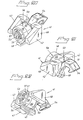
- the locking system 40 comprises, see Figures 20 - 24 , a fastening device 41 arranged at the back side 17 of the holder 4, comprising a fitting device 42 designed to precisely fit into the cavity's 14 open rear, extended part 19 between two blades 43, 44, which suitably extend as a continuation, essentially in the axial direction, of the lengthwise side walls 22 of the notch 14 and toward two essentially vertical stop surfaces 45, 46 arranged transversely to the holder 4, one on either side of the notch 14.
- the fitting device 42 comprises three L-shaped fitting pieces 47, 48, 49 attached at a central, circular front support plate 50 and through which supporting plate 50 a central hole 51 is made.
- the fastening device 41 comprises a bolt 53, see Figure 23 , which is arranged centrally through the fitting device 42 and support plate's hole 51.
- the bolt 53 has a claw or hook 54 arranged at the front end and a thread 55 on the rearward facing end intended for a rear tensioning and locking device 56.
- a preferred embodiment of the tensioning and locking device 56 comprises a rear, with its internal bottom 57 sealed, sleeve 58 and a locking nut 59 that is rotatably arranged on said threaded bolt 53, inside said sleeve 58 and against said sealed bottom 57. Threaded on the bolt 53, between the sleeve's 58 sealed bottom 57 and the support plate 50, there is also an elastic body 60 arranged, through which a certain, determined pretensioning force can be transferred in an adjustable manner from the holder 4 to the tooth portion 5 through the tensioning device 41 in the form of a, under operation, dynamic, though always tensile, thus, always uniting axial force every time a new tooth portion 5 is installed even when the holder 4 is worn.
- the placement of the tensioning device 41 at the rear end 17, 19 of the holder 4 in the present tooth system 1 protects the actual locking mechanism against damage from moved earthen masses, loosened by means of the tool 2, at the same time as the locking device 56 of the particular locking system 40 may be fitted and disassembled in a simpler and more efficient manner using some standard tool, expediently a pneumatic or electric-powered wrench, without causing a substantial hazard for damage.
- the claw or hook 54 of the tensioning device 41 is arranged to grip in or around a recess or hook device 61 interacting with the tensioning device 41 and expediently arranged on the rear end 52 of the tooth portion 5.
- the tooth system 1 different types of locking systems and/or modifications of the locking system, itself, can be used, without essential adaptation of the tooth portion 5 and/or connection parts 4, 5 to the given locking system and/or its modifications.
- the locking system 40 also can not be affected by the problems of the holder's locking device opening no longer fitting the worn tooth portion's protruding locking device opening, which so often do affect conventional tooth systems as known by prior art.
- the locking device 56 is installed, adjusted and removed axially at the rear end 17 of the tooth system 1 and this is done without possible deformations of the joint connection geometry complicating the work to be done.
- the tensioning device 41 is, thus, configured in such a way that it provides adjustable, elastic pretensioning that tightness the holder 4 relative to the tooth portion 5, essentially internally along the notch and axially along the cavity's 14 axial symmetry axis Y, that is, essentially rearwards in relation to the tool's 2 direction of work and in which the multi-armed form and the pretensioning guarantee that the tooth portion 5 will always be situated in a predetermined position relative to the holder 4 and, thus, also in relation to the given tool 2 and also the working surface (W) throughout the tooth system's 1 entire life cycle.
Claims (23)
- Système denté (1) conçu pour un outil (2) d'une machine de terrassement (3), lequel système denté (1) est du type intégrant un support (4) pouvant être fixé à l'outil (2) et une partie dentée avant (5), qui est agencée de manière amovible par rapport au support (4) et sur celui-ci et est sous forme d'une pièce d'usure remplaçable et/ou d'une pièce de rechange conçue pour le terrassement réel (W), laquelle partie dentée (5) comprend un pied arrière (13) et le support (4) comprend une cavité (14) conçue pour recevoir le pied arrière (13) en coopération avec la partie dentée (5) et obtient ainsi un raccord commun (A, B, C, D) pour l'absorption de forces produites (Fs, Fc, Fp) grâce à une géométrie de raccordement prédéterminée comprenant des surfaces de contact (15) opposées, spéciales, interagissant mutuellement et, au moins initialement, des surfaces de dégagement (16) qui sont agencées le long de la partie dentée (5) et du support (4), et un dispositif tendeur (41) est disposé au niveau de la partie arrière (19) de la cavité (14) pour permettre un resserrement et/ou une précontrainte réglable de la partie dentée (5) par rapport au support (4) de manière essentiellement axiale le long de l'axe de symétrie longitudinale Y de la cavité (14), dans lequel le pied denté (13) et la cavité (14), le long d'au moins une partie avant (C) dudit raccord (A, B, C, D) ont une section transversale cruciforme à plusieurs bras (T1) comprenant quatre bras de projection (31, 32, 33, 34), et quatre rainures (24, 28, 29, 30) interagissant chacune avec un bras de projection (31, 32, 33, 34).
- Système denté (1) conformément à la revendication 1, dans lequel les bras de projection (31, 32, 33, 34) comprennent au moins un bras (31) disposé de manière essentiellement verticale ou un talon (34) et deux parties ailes (32, 33), disposées de manière essentiellement latérale vers ceux-ci.
- Système denté (1) conformément à la revendication 1, dans lequel les bras de projection (31, 32, 33, 34) comprennent un bras supérieur (31) disposé de manière essentiellement verticale, un talon inférieur (34) disposé de manière essentiellement verticale et deux parties ailes (32, 33) latérales agencées de manière essentiellement horizontale.
- Système denté (1) conformément aux revendications 1, 2 ou 3, dans lequel le pied denté (13) présente une section transversale (T2) convergente vers l'arrière.
- Système denté (1) conformément à la revendication 4, dans lequel la cavité (14) est conçue sous forme d'encoche (14) convergeant vers l'intérieur du support (4).
- Système denté (1) conformément à l'une quelconque des revendications précédentes, dans lequel la cavité (14) est constituée par une encoche (14) s'ouvrant vers l'arrière (19) et vers le haut (24) le long du côté supérieur du support (4).
- Système denté (1) conformément à l'une quelconque des revendications précédentes, dans lequel une section transversale (T2) dans une partie médiane (20) de la cavité (14) comprend une partie triangulaire inférieure tronquée avec des coins essentiellement arrondis (22), où le côté inférieur émoussé forme le fond (23) de la cavité (14) et où les coins inférieurs (22) de la section transversale (T2) comprennent de préférence des surfaces de dégagement (16) longitudinales, tandis que le prolongement vers le haut de la section transversale (T2) est essentiellement formé par des côtés longitudinaux orientés vers l'intérieur (25), destinés à former des zones de contact en interaction (15) conjointement avec les surfaces latérales (D1, D2) du pied denté (13) et par la suite par des parois latérales (26), longitudinales, essentiellement verticales, à une certaine distance les unes des autres formant un collet d'encoche supérieur (24) ouvert vers le haut.
- Système denté (1) conformément à l'une quelconque des revendications précédentes, dans lequel chacune des rainures (24, 28, 29, 30) dans une partie avant (21) de la cavité (14) comprend une dilatation vers l'extérieur de la section transversale d'encoche (T1) de l'intérieur de la cavité (14) et vers l'avant par rapport à l'axe de symétrie longitudinale Y.
- Système denté (1) conformément à l'une quelconque des revendications précédentes, dans lequel une partie médiane (20) de la cavité (14) présente un jeu (16) disposé dans la partie entre les côtés inférieurs (H1, H2) du pied denté (13) et les côtés longitudinaux (22) de la cavité (14) au fond (23) de la cavité, et dans la partie entre les côtés (39) de la partie dorsale (37) de la partie dentée (5) et les côtés longitudinaux supérieurs (26) de la cavité (24) et entre le pied denté (13) en-dessous (E1, E2) et le fond (23) de la cavité (14).
- Système denté (1) conformément à l'une quelconque des revendications précédentes en combinaison avec la revendication 6, dans lequel la partie dentée (5) comprend une partie dorsale (37) faisant saillie à travers l'encoche ouverte (24).
- Système denté (1) conformément à la revendication 10, dans lequel un renfort de matériau secondaire (36) est disposé au niveau de la partie dorsale (37) de la partie dentée (5).
- Système denté (1) conformément à la revendication 1, dans lequel des surfaces de contact (15) sont disposées le long d'une partie arrière (D) du raccord (A, B, C, D) entre le support et les dents (4, 5), suivant un angle très aigu δ, qui est inférieur à 10°, par rapport à l'axe de symétrie longitudinale Y ou parallèle à celui-ci.
- Système denté (1) conformément à l'une quelconque des revendications précédentes, dans lequel la partie dentée (5) ou le support (4) comporte un talon de couple en saillie (34) et la partie de liaison opposée (4 ou 5) comprend une dépression correspondante (30), interagissant avec le talon (34) pour absorber les forces transversales heurtant latéralement (Fp), qui heurtent de manière perpendiculaire à l'axe de symétrie longitudinale Y.
- Système denté (1) conformément à l'une quelconque des revendications précédentes, dans lequel les bras de projection (31, 32, 33, 34) sont constitués par un point denté (31), symétriquement agencé vers le haut et essentiellement quelque peu incliné vers l'avant, et les deux parties ailes (32, 33) latérales, agencées de manière essentiellement horizontale, symétriques sur chaque côté du point denté (31) et un talon (34) conçu vers le bas de manière essentiellement verticale.
- Système denté (1) conformément à l'une quelconque des revendications précédentes, dans lequel, après l'assemblage du support (4) et de la partie dentée (5), une zone de choc (A, B) au début du raccord (C) entre eux, forme une zone de butée commune, dont les surfaces de butée (15) comprennent le côté avant (A) du support (4) et le côté arrière opposé (B) de la partie dentée (5), où la plus grande partie des surfaces (B) de la partie dentée (5) qui est en contact avec le côté avant (A) du support (4), est située sur le même côté que le support (4) d'un plan vertical imaginaire (XZ) directement positionné en face des parties les plus en avant du support (4).
- Système denté (1) conformément à l'une quelconque des revendications précédentes, dans lequel essentiellement la plus grande partie des forces (Fs, Fc, Fp) et les couples en résultant sont absorbées à travers des surfaces de contact (15) principalement au niveau de la partie avant du raccord (C).
- Système denté (1) conformément à l'une des revendications 2 à 16, dans lequel les zones de contact pour l'absorption des forces de treuil (Fs), ainsi que les couples en résultant, sont disposés le long des surfaces de contact inférieures (F1 et F2) au niveau des deux parties ailes latérales (32, 33) de la partie dentée (5) et des surfaces de contact supérieures (D1 et D2) au niveau du côté supérieur du pied denté (13).
- Système denté (1) conformément à l'une quelconque des revendications 2 à 17, dans lequel les zones de contact pour l'absorption de la force de cisaillement (Fc), ainsi que les couples en résultant, sont disposés le long des surfaces de contact supérieures (B1 et B2) au niveau des deux parties ailes latérales (32, 33) de la partie dentée (5) et des surfaces de contact inférieures (E1 et E2) au niveau du côté inférieur du pied denté (13).
- Système denté (1) selon l'une quelconque des revendications 2 à 18, dans lequel les zones de contact pour l'absorption de la force transversale (Fp), ainsi que les couples en résultant, en fonction d'une direction de choc d'une force donnée (Fp), sont disposés le long d'au moins une surface (G2) de contact longitudinal, essentiellement verticale, au niveau du talon de couple (34), au moins une surface de contact (D1) supérieure, inclinée, longitudinale au niveau du côté supérieur du pied denté (13), au moins une surface de contact (F2), inférieure, latérale, essentiellement horizontale, au niveau de l'une des parties ailes latérales (33) de la partie dentée (5), au moins une surface de contact (B1) supérieure, inclinée au niveau de l'autre partie aile latérale (32) de la partie dentée (5) et au moins une surface de contact (C1) supérieure, latérale, essentiellement horizontale, au niveau de l'autre partie aile latérale (32) de la partie dentée ; ou, pour une force (Fp) à partir de la direction opposée, essentiellement à travers les surfaces de contact correspondantes (G1, D2, F1, B2 et C2).
- Système denté (1) conformément à l'une quelconque des revendications 2 à 19, dans lequel le rapport de levage des forces normales (Fs), transversales (Fp) et de cisaillement (Fc) par rapport à l'axe de symétrie axiale Y et un point d'appui, de préférence le talon (34), autour duquel la torsion se produit dans le raccord entre les parties de liaison (4, 5) où la longueur en saillie de la partie dentée (5) le long l'axe de symétrie longitudinale Y à partir dudit point d'appui définit le premier bras de levier (b) et où la longueur le long de l'axe de symétrie longitudinale Y du pied dentée (13) inséré dans le support (4) à partir dudit point d'appui définit le deuxième bras de levier (r), est inférieure à un, qui est (b)/(r)<1.
- Système denté (1) conformément à l'une quelconque des revendications précédentes, dans lequel le dispositif de fixation (41) pouvant être fixé de manière amovible au niveau du côté arrière (17) du support (4) comprend un dispositif de raccord (42), qui est conçu pour s'adapter de la partie arrière ouverte (19) de la cavité (14) et contre la surface d'extrémité (52) du pied denté (13), un boulon (53) fileté (55), qui est disposé à travers le dispositif de raccord (42), avec une griffe ou un crochet (54) avant pour interagir avec un évidement ou un dispositif de crochet (61) disposé au niveau de la partie dentée (5), et un dispositif de verrouillage et de précontrainte arrière (56) comprenant un corps élastique (60) et un mécanisme de verrouillage (59) pour réaliser une fixité dynamique et un positionnement fiable à une position prédéterminée par la partie dentée remplaçable (5) au niveau du support (4) à travers la forme à bras multiples et la force de précontrainte réglable.
- Système denté (1) conformément à l'une quelconque des revendications précédentes, dans lequel le système denté (1) comprend un insert amovible, approprié à des métaux durs, au niveau de la partie arrière (D) du raccord (A, B, C, D) dans la cavité (14), lequel insert absorbe les forces de surface entre les parties de liaison en interaction du support (4) et de la partie dentée (5).
- Système denté (1) conformément à l'une quelconque des revendications précédentes, dans lequel la machine de terrassement (3), l'outil (2) et les pièces d'usure et/ou de rechange (5) pour l'enlèvement et la rupture de masses à partir d'une surface de travail (W), sont en particulier exemplifiés par un trépan (2) d'un dispositif de coupe (3) de drague avec ses dents d'usure remplaçables (5).
Applications Claiming Priority (2)
| Application Number | Priority Date | Filing Date | Title |
|---|---|---|---|
| SE0302061A SE0302061L (sv) | 2003-07-11 | 2003-07-11 | Tandsystem |
| PCT/SE2004/001075 WO2005005737A1 (fr) | 2003-07-11 | 2004-07-02 | Systeme dente |
Publications (2)
| Publication Number | Publication Date |
|---|---|
| EP1644588A1 EP1644588A1 (fr) | 2006-04-12 |
| EP1644588B1 true EP1644588B1 (fr) | 2013-01-02 |
Family
ID=27764982
Family Applications (1)
| Application Number | Title | Priority Date | Filing Date |
|---|---|---|---|
| EP04749111A Active EP1644588B1 (fr) | 2003-07-11 | 2004-07-02 | Un système dente pour un engin de terrassement |
Country Status (17)
| Country | Link |
|---|---|
| US (2) | US7694443B2 (fr) |
| EP (1) | EP1644588B1 (fr) |
| JP (1) | JP4571634B2 (fr) |
| KR (1) | KR101088224B1 (fr) |
| CN (1) | CN1849428B (fr) |
| AU (1) | AU2004256377B2 (fr) |
| BR (1) | BRPI0412497B1 (fr) |
| CA (1) | CA2532153C (fr) |
| DK (1) | DK1644588T3 (fr) |
| EA (1) | EA007547B1 (fr) |
| EG (1) | EG24114A (fr) |
| ES (1) | ES2400818T3 (fr) |
| HK (1) | HK1094901A1 (fr) |
| MX (1) | MXPA06000439A (fr) |
| SE (1) | SE0302061L (fr) |
| WO (1) | WO2005005737A1 (fr) |
| ZA (1) | ZA200600233B (fr) |
Families Citing this family (27)
| Publication number | Priority date | Publication date | Assignee | Title |
|---|---|---|---|---|
| US6729052B2 (en) * | 2001-11-09 | 2004-05-04 | Esco Corporation | Assembly for securing an excavating tooth |
| SE0302061L (sv) * | 2003-07-11 | 2004-07-20 | Combi Wear Parts Ab | Tandsystem |
| US7114272B2 (en) | 2003-09-09 | 2006-10-03 | H&L Tooth Company | Winged digging tooth |
| KR101316443B1 (ko) * | 2006-09-01 | 2013-10-08 | 메탈로제니아, 에스.에이. | 준설 기계용 치상부재 및 어댑터 |
| ATE467726T1 (de) * | 2007-06-01 | 2010-05-15 | Ihc Holland Ie Bv | Zahnsystem |
| SE532815C2 (sv) * | 2007-11-09 | 2010-04-13 | Combi Wear Parts Ab | Självskärpande, autosignalerande slitdel |
| BE1018563A4 (nl) * | 2009-01-09 | 2011-03-01 | Dredging Int | Snijkop voor het baggeren van ondergrond en gebruik van deze snijkop voor het baggeren van ondergrond. |
| DE102009029894B4 (de) * | 2009-06-23 | 2019-03-21 | Betek Gmbh & Co. Kg | Bodenbearbeitungswerkzeug |
| NL2004771C2 (en) * | 2010-05-26 | 2011-11-29 | Ihc Holland Ie Bv | Tooth system. |
| WO2012006664A1 (fr) * | 2010-07-13 | 2012-01-19 | Bradken Resources Pty Limited | Ensemble dent d'excavation |
| AU2011253666B8 (en) | 2010-11-30 | 2014-09-25 | Joy Global Surface Mining Inc | Pick Assembly |
| WO2012072801A2 (fr) * | 2010-12-03 | 2012-06-07 | Wirtgen Gmbh | Porte-burin et système de porte-burin comprenant un porte-burin et une partie de base |
| CN103174187B (zh) * | 2013-03-19 | 2015-04-15 | 中交天津港航勘察设计研究院有限公司 | 一种挖土机具用卡环齿装置 |
| US10378187B2 (en) | 2014-03-07 | 2019-08-13 | Vermeer Manufacturing Company | Replaceable mounting apparatus for reducing elements |
| USD746340S1 (en) * | 2014-04-11 | 2015-12-29 | Vermeer Manufacturing Company | Mounting block for reducing elements |
| USD746878S1 (en) * | 2014-04-11 | 2016-01-05 | Vermeer Manufacturing Company | Mounting block for reducing elements |
| EP2966228A1 (fr) | 2014-07-11 | 2016-01-13 | Metalogenia Research & Technologies S.L. | Dent et adaptateur pour une machine de dragage |
| TR201815004T4 (tr) * | 2015-02-13 | 2018-11-21 | Caterpillar Work Tools Bv | Bir tahrip aletine yönelik bir diş bloğu. |
| NL2015612B1 (en) * | 2015-10-14 | 2017-05-08 | Ihc Holland Ie Bv | Snail tooth. |
| NL2015672B1 (en) | 2015-10-28 | 2017-05-29 | Ihc Holland Ie Bv | Tooth retaining and locking system. |
| NL2015785B1 (en) * | 2015-11-13 | 2017-06-02 | Ihc Holland Ie Bv | Adapter system for cutting tooth. |
| CN205284046U (zh) * | 2016-01-22 | 2016-06-08 | 刘高 | 粉碎农田砾石的刀头 |
| USD798913S1 (en) * | 2016-02-04 | 2017-10-03 | Beaver Mulching Inc. | Combined mulching tooth and depth limiter |
| NL2017180B1 (en) | 2016-07-18 | 2018-01-24 | Ihc Holland Ie Bv | Additive manufactured tooth for dredging or mining |
| EP3358089A1 (fr) | 2017-02-07 | 2018-08-08 | Leo Dynamische Investering B.V. | Tête de coupe et système denté |
| US20210071387A1 (en) * | 2019-09-10 | 2021-03-11 | Caterpillar Inc. | Cutting component with fastening portion |
| US11766003B2 (en) * | 2020-02-04 | 2023-09-26 | Capital D'investissement Carrier Inc. | Excavating assembly and tree felling head including same |
Family Cites Families (27)
| Publication number | Priority date | Publication date | Assignee | Title |
|---|---|---|---|---|
| US2148309A (en) * | 1937-11-05 | 1939-02-21 | Stephens Henry | Mining cutter |
| US2167425A (en) * | 1938-12-22 | 1939-07-25 | Page Engineering Company | Tooth-point construction |
| US2385395A (en) * | 1944-02-11 | 1945-09-25 | Electric Steel Foundry | Excavating tooth |
| US2613069A (en) * | 1948-10-15 | 1952-10-07 | Cincinnati Mine Machinery Co | Mining machine bit and block |
| US2791414A (en) * | 1954-07-30 | 1957-05-07 | Cincinnati Mine Machinery Co | Cutter bit and holder |
| US3349508A (en) * | 1965-09-07 | 1967-10-31 | Petersen Anita E | Tooth with t-shaped shank |
| GB1297827A (fr) * | 1970-08-25 | 1972-11-29 | ||
| NL164633B (nl) * | 1971-02-11 | 1980-08-15 | Hattum En Blankevoort N V Van | Snijkopconstructie. |
| JPS5214562Y2 (fr) * | 1972-10-13 | 1977-04-01 | ||
| US4050172A (en) * | 1974-01-07 | 1977-09-27 | Petersen Gerald A | Excavator tooth, holder therefor and staple retainer |
| US4275929A (en) * | 1978-08-25 | 1981-06-30 | The Cincinnati Mine Machinery Company | Means for removably affixing a cutter bit mounting lug to a base member on the driven element of a mining machine or the like |
| US4240669A (en) * | 1978-10-02 | 1980-12-23 | Joy Manufacturing Company | Mining cutter bit holder and mounting assemblies |
| US4261620A (en) * | 1979-10-30 | 1981-04-14 | Carmet Company | Tapered lock pin for a cutter tool bit |
| US4320925A (en) * | 1980-02-14 | 1982-03-23 | Florida Machine & Foundry Co. | Dredge cutterhead tooth |
| US4343516A (en) * | 1980-08-11 | 1982-08-10 | Ingersoll-Rand Company | Cutter bit assembly |
| US4693518A (en) * | 1981-01-08 | 1987-09-15 | Kennametal, Inc. | Means for holding cutter bits |
| US4542943A (en) * | 1982-04-08 | 1985-09-24 | Kennametal Inc. | Earthworking tool for protecting from abnormally high cutting loads |
| DE3339558A1 (de) * | 1982-11-13 | 1985-05-09 | Peters, Albert, 4000 Düsseldorf | Gewinnungseinrichtung mit dreh-kippmeissel und geschlossener meisseltasche |
| DE3444563A1 (de) * | 1984-12-06 | 1986-06-19 | Lehnhoff Hartstahl GmbH & Co, 7570 Baden-Baden | Baggerzahn-anordnung |
| US4621871A (en) * | 1985-06-19 | 1986-11-11 | Koehring Company | Quickly replaceable cutter socket |
| GB8717116D0 (en) * | 1987-07-20 | 1987-08-26 | Wimet Mining Ltd | Cutter picks |
| US5011229A (en) * | 1988-11-09 | 1991-04-30 | Joy Technologies Inc. | Miner cutting bit holding apparatus |
| US4915455A (en) * | 1988-11-09 | 1990-04-10 | Joy Technologies Inc. | Miner cutting bit holding apparatus |
| EP0649945B1 (fr) * | 1993-08-30 | 1996-04-17 | Baz Service Ag | Dent d'excavatrice |
| ES2158805B1 (es) * | 1999-10-01 | 2002-04-01 | Metalogenia Sa | Perfeccionamientos en los acoplamientos para dientes de maquinas para movimiento de tierras. |
| US6854810B2 (en) * | 2000-12-20 | 2005-02-15 | Kennametal Inc. | T-shaped cutter tool assembly with wear sleeve |
| SE0302061L (sv) * | 2003-07-11 | 2004-07-20 | Combi Wear Parts Ab | Tandsystem |
-
2003
- 2003-07-11 SE SE0302061A patent/SE0302061L/xx not_active IP Right Cessation
-
2004
- 2004-07-02 US US10/563,968 patent/US7694443B2/en active Active
- 2004-07-02 MX MXPA06000439A patent/MXPA06000439A/es active IP Right Grant
- 2004-07-02 CA CA2532153A patent/CA2532153C/fr active Active
- 2004-07-02 JP JP2006520137A patent/JP4571634B2/ja active Active
- 2004-07-02 ES ES04749111T patent/ES2400818T3/es active Active
- 2004-07-02 EP EP04749111A patent/EP1644588B1/fr active Active
- 2004-07-02 CN CN2004800260520A patent/CN1849428B/zh active Active
- 2004-07-02 KR KR1020067000617A patent/KR101088224B1/ko active IP Right Grant
- 2004-07-02 EA EA200600238A patent/EA007547B1/ru unknown
- 2004-07-02 DK DK04749111.3T patent/DK1644588T3/da active
- 2004-07-02 AU AU2004256377A patent/AU2004256377B2/en active Active
- 2004-07-02 WO PCT/SE2004/001075 patent/WO2005005737A1/fr active Application Filing
- 2004-07-02 BR BRPI0412497A patent/BRPI0412497B1/pt active IP Right Grant
- 2004-07-21 ZA ZA200600233A patent/ZA200600233B/en unknown
-
2006
- 2006-01-14 EG EGNA2006000027 patent/EG24114A/xx active
-
2007
- 2007-02-26 HK HK07102129.3A patent/HK1094901A1/xx unknown
-
2010
- 2010-03-16 US US12/724,824 patent/US7971375B2/en active Active
Also Published As
| Publication number | Publication date |
|---|---|
| EA200600238A1 (ru) | 2006-08-25 |
| JP4571634B2 (ja) | 2010-10-27 |
| SE0302061D0 (sv) | 2003-07-11 |
| ZA200600233B (en) | 2007-03-28 |
| US7971375B2 (en) | 2011-07-05 |
| HK1094901A1 (en) | 2007-04-13 |
| AU2004256377A1 (en) | 2005-01-20 |
| WO2005005737A1 (fr) | 2005-01-20 |
| EG24114A (en) | 2008-06-29 |
| CN1849428B (zh) | 2012-04-04 |
| DK1644588T3 (da) | 2013-02-18 |
| KR20060041218A (ko) | 2006-05-11 |
| ES2400818T3 (es) | 2013-04-12 |
| MXPA06000439A (es) | 2006-08-23 |
| AU2004256377B2 (en) | 2009-08-20 |
| CN1849428A (zh) | 2006-10-18 |
| SE524301C2 (sv) | 2004-07-20 |
| EP1644588A1 (fr) | 2006-04-12 |
| EA007547B1 (ru) | 2006-10-27 |
| BRPI0412497A (pt) | 2006-09-19 |
| CA2532153A1 (fr) | 2005-01-20 |
| US20070245602A1 (en) | 2007-10-25 |
| BRPI0412497B1 (pt) | 2015-09-08 |
| CA2532153C (fr) | 2012-09-11 |
| US20100170120A1 (en) | 2010-07-08 |
| SE0302061L (sv) | 2004-07-20 |
| KR101088224B1 (ko) | 2011-11-30 |
| JP2007521429A (ja) | 2007-08-02 |
| US7694443B2 (en) | 2010-04-13 |
Similar Documents
| Publication | Publication Date | Title |
|---|---|---|
| US7971375B2 (en) | Tooth system | |
| CA3010637C (fr) | Ensembles de couplage avec reprise amelioree | |
| CN1800522B (zh) | 耐磨组件及耐磨构件 | |
| US6839990B2 (en) | Excavator teeth | |
| JP4584247B2 (ja) | 掘削機の掘削縁部用の磨耗アッセンブリ | |
| JP2007521429A5 (fr) | ||
| MX2014004314A (es) | Ensamble de diente de herramienta de acoplamiento de tierra con punta y adaptador. | |
| CA3125978C (fr) | Broche de machinerie lourde avec cliquet | |
| SK4012002A3 (en) | Working tool with replaceable working bit | |
| WO2018147724A1 (fr) | Tête de coupe et système d'outil | |
| AU2002301249B2 (en) | Excavator teeth | |
| OA16239A (en) | Coupling assemblies with enhanced take up. | |
| JPH05311703A (ja) | 保持用クランプ及び切削刃組立体 |
Legal Events
| Date | Code | Title | Description |
|---|---|---|---|
| PUAI | Public reference made under article 153(3) epc to a published international application that has entered the european phase |
Free format text: ORIGINAL CODE: 0009012 |
|
| 17P | Request for examination filed |
Effective date: 20060125 |
|
| AK | Designated contracting states |
Kind code of ref document: A1 Designated state(s): AT BE BG CH CY CZ DE DK EE ES FI FR GB GR HU IE IT LI LU MC NL PL PT RO SE SI SK TR |
|
| DAX | Request for extension of the european patent (deleted) | ||
| 17Q | First examination report despatched |
Effective date: 20101111 |
|
| RTI1 | Title (correction) |
Free format text: A TOOTH SYSTEM FOR AN EARTH MOVING MACHINERY |
|
| GRAP | Despatch of communication of intention to grant a patent |
Free format text: ORIGINAL CODE: EPIDOSNIGR1 |
|
| GRAJ | Information related to disapproval of communication of intention to grant by the applicant or resumption of examination proceedings by the epo deleted |
Free format text: ORIGINAL CODE: EPIDOSDIGR1 |
|
| GRAS | Grant fee paid |
Free format text: ORIGINAL CODE: EPIDOSNIGR3 |
|
| GRAA | (expected) grant |
Free format text: ORIGINAL CODE: 0009210 |
|
| AK | Designated contracting states |
Kind code of ref document: B1 Designated state(s): AT BE BG CH CY CZ DE DK EE ES FI FR GB GR HU IE IT LI LU MC NL PL PT RO SE SI SK TR |
|
| REG | Reference to a national code |
Ref country code: GB Ref legal event code: FG4D |
|
| REG | Reference to a national code |
Ref country code: CH Ref legal event code: EP Ref country code: AT Ref legal event code: REF Ref document number: 591716 Country of ref document: AT Kind code of ref document: T Effective date: 20130115 |
|
| REG | Reference to a national code |
Ref country code: IE Ref legal event code: FG4D |
|
| REG | Reference to a national code |
Ref country code: DK Ref legal event code: T3 |
|
| REG | Reference to a national code |
Ref country code: DE Ref legal event code: R096 Ref document number: 602004040634 Country of ref document: DE Effective date: 20130228 |
|
| REG | Reference to a national code |
Ref country code: ES Ref legal event code: FG2A Ref document number: 2400818 Country of ref document: ES Kind code of ref document: T3 Effective date: 20130412 |
|
| REG | Reference to a national code |
Ref country code: NL Ref legal event code: T3 |
|
| REG | Reference to a national code |
Ref country code: AT Ref legal event code: MK05 Ref document number: 591716 Country of ref document: AT Kind code of ref document: T Effective date: 20130102 |
|
| PG25 | Lapsed in a contracting state [announced via postgrant information from national office to epo] |
Ref country code: SI Free format text: LAPSE BECAUSE OF FAILURE TO SUBMIT A TRANSLATION OF THE DESCRIPTION OR TO PAY THE FEE WITHIN THE PRESCRIBED TIME-LIMIT Effective date: 20130102 |
|
| PG25 | Lapsed in a contracting state [announced via postgrant information from national office to epo] |
Ref country code: BG Free format text: LAPSE BECAUSE OF FAILURE TO SUBMIT A TRANSLATION OF THE DESCRIPTION OR TO PAY THE FEE WITHIN THE PRESCRIBED TIME-LIMIT Effective date: 20130402 Ref country code: AT Free format text: LAPSE BECAUSE OF FAILURE TO SUBMIT A TRANSLATION OF THE DESCRIPTION OR TO PAY THE FEE WITHIN THE PRESCRIBED TIME-LIMIT Effective date: 20130102 Ref country code: CY Free format text: LAPSE BECAUSE OF FAILURE TO SUBMIT A TRANSLATION OF THE DESCRIPTION OR TO PAY THE FEE WITHIN THE PRESCRIBED TIME-LIMIT Effective date: 20130102 Ref country code: CZ Free format text: LAPSE BECAUSE OF FAILURE TO SUBMIT A TRANSLATION OF THE DESCRIPTION OR TO PAY THE FEE WITHIN THE PRESCRIBED TIME-LIMIT Effective date: 20130102 Ref country code: SE Free format text: LAPSE BECAUSE OF FAILURE TO SUBMIT A TRANSLATION OF THE DESCRIPTION OR TO PAY THE FEE WITHIN THE PRESCRIBED TIME-LIMIT Effective date: 20130102 |
|
| PG25 | Lapsed in a contracting state [announced via postgrant information from national office to epo] |
Ref country code: GR Free format text: LAPSE BECAUSE OF FAILURE TO SUBMIT A TRANSLATION OF THE DESCRIPTION OR TO PAY THE FEE WITHIN THE PRESCRIBED TIME-LIMIT Effective date: 20130403 Ref country code: PL Free format text: LAPSE BECAUSE OF FAILURE TO SUBMIT A TRANSLATION OF THE DESCRIPTION OR TO PAY THE FEE WITHIN THE PRESCRIBED TIME-LIMIT Effective date: 20130102 Ref country code: FI Free format text: LAPSE BECAUSE OF FAILURE TO SUBMIT A TRANSLATION OF THE DESCRIPTION OR TO PAY THE FEE WITHIN THE PRESCRIBED TIME-LIMIT Effective date: 20130102 Ref country code: PT Free format text: LAPSE BECAUSE OF FAILURE TO SUBMIT A TRANSLATION OF THE DESCRIPTION OR TO PAY THE FEE WITHIN THE PRESCRIBED TIME-LIMIT Effective date: 20130502 |
|
| PG25 | Lapsed in a contracting state [announced via postgrant information from national office to epo] |
Ref country code: SK Free format text: LAPSE BECAUSE OF FAILURE TO SUBMIT A TRANSLATION OF THE DESCRIPTION OR TO PAY THE FEE WITHIN THE PRESCRIBED TIME-LIMIT Effective date: 20130102 Ref country code: EE Free format text: LAPSE BECAUSE OF FAILURE TO SUBMIT A TRANSLATION OF THE DESCRIPTION OR TO PAY THE FEE WITHIN THE PRESCRIBED TIME-LIMIT Effective date: 20130102 Ref country code: RO Free format text: LAPSE BECAUSE OF FAILURE TO SUBMIT A TRANSLATION OF THE DESCRIPTION OR TO PAY THE FEE WITHIN THE PRESCRIBED TIME-LIMIT Effective date: 20130102 |
|
| PLBE | No opposition filed within time limit |
Free format text: ORIGINAL CODE: 0009261 |
|
| STAA | Information on the status of an ep patent application or granted ep patent |
Free format text: STATUS: NO OPPOSITION FILED WITHIN TIME LIMIT |
|
| 26N | No opposition filed |
Effective date: 20131003 |
|
| REG | Reference to a national code |
Ref country code: DE Ref legal event code: R097 Ref document number: 602004040634 Country of ref document: DE Effective date: 20131003 |
|
| PG25 | Lapsed in a contracting state [announced via postgrant information from national office to epo] |
Ref country code: MC Free format text: LAPSE BECAUSE OF FAILURE TO SUBMIT A TRANSLATION OF THE DESCRIPTION OR TO PAY THE FEE WITHIN THE PRESCRIBED TIME-LIMIT Effective date: 20130102 |
|
| REG | Reference to a national code |
Ref country code: CH Ref legal event code: PL |
|
| REG | Reference to a national code |
Ref country code: IE Ref legal event code: MM4A |
|
| PG25 | Lapsed in a contracting state [announced via postgrant information from national office to epo] |
Ref country code: CH Free format text: LAPSE BECAUSE OF NON-PAYMENT OF DUE FEES Effective date: 20130731 Ref country code: LI Free format text: LAPSE BECAUSE OF NON-PAYMENT OF DUE FEES Effective date: 20130731 |
|
| PG25 | Lapsed in a contracting state [announced via postgrant information from national office to epo] |
Ref country code: IE Free format text: LAPSE BECAUSE OF NON-PAYMENT OF DUE FEES Effective date: 20130702 |
|
| PG25 | Lapsed in a contracting state [announced via postgrant information from national office to epo] |
Ref country code: HU Free format text: LAPSE BECAUSE OF FAILURE TO SUBMIT A TRANSLATION OF THE DESCRIPTION OR TO PAY THE FEE WITHIN THE PRESCRIBED TIME-LIMIT; INVALID AB INITIO Effective date: 20040702 |
|
| REG | Reference to a national code |
Ref country code: FR Ref legal event code: PLFP Year of fee payment: 13 |
|
| REG | Reference to a national code |
Ref country code: FR Ref legal event code: PLFP Year of fee payment: 14 |
|
| REG | Reference to a national code |
Ref country code: FR Ref legal event code: PLFP Year of fee payment: 15 |
|
| PGFP | Annual fee paid to national office [announced via postgrant information from national office to epo] |
Ref country code: TR Payment date: 20230622 Year of fee payment: 20 Ref country code: NL Payment date: 20230726 Year of fee payment: 20 Ref country code: LU Payment date: 20230727 Year of fee payment: 20 |
|
| REG | Reference to a national code |
Ref country code: DE Ref legal event code: R082 Ref document number: 602004040634 Country of ref document: DE Representative=s name: GLAWE DELFS MOLL PARTNERSCHAFT MBB VON PATENT-, DE |
|
| PGFP | Annual fee paid to national office [announced via postgrant information from national office to epo] |
Ref country code: IT Payment date: 20230720 Year of fee payment: 20 Ref country code: GB Payment date: 20230727 Year of fee payment: 20 Ref country code: ES Payment date: 20230804 Year of fee payment: 20 |
|
| PGFP | Annual fee paid to national office [announced via postgrant information from national office to epo] |
Ref country code: FR Payment date: 20230725 Year of fee payment: 20 Ref country code: DK Payment date: 20230727 Year of fee payment: 20 Ref country code: DE Payment date: 20230727 Year of fee payment: 20 Ref country code: BE Payment date: 20230727 Year of fee payment: 20 |