EP1643766A1 - Informationsaufzeichnungseinrichtung, informationsaufzeichnungsverfahren, informationübertragungseinrichtung und informationsübertragungsverfahren - Google Patents
Informationsaufzeichnungseinrichtung, informationsaufzeichnungsverfahren, informationübertragungseinrichtung und informationsübertragungsverfahren Download PDFInfo
- Publication number
- EP1643766A1 EP1643766A1 EP04745639A EP04745639A EP1643766A1 EP 1643766 A1 EP1643766 A1 EP 1643766A1 EP 04745639 A EP04745639 A EP 04745639A EP 04745639 A EP04745639 A EP 04745639A EP 1643766 A1 EP1643766 A1 EP 1643766A1
- Authority
- EP
- European Patent Office
- Prior art keywords
- information
- recording
- event
- border
- partial
- Prior art date
- Legal status (The legal status is an assumption and is not a legal conclusion. Google has not performed a legal analysis and makes no representation as to the accuracy of the status listed.)
- Withdrawn
Links
Images


Classifications
-
- H—ELECTRICITY
- H04—ELECTRIC COMMUNICATION TECHNIQUE
- H04N—PICTORIAL COMMUNICATION, e.g. TELEVISION
- H04N5/00—Details of television systems
- H04N5/76—Television signal recording
- H04N5/91—Television signal processing therefor
- H04N5/92—Transformation of the television signal for recording, e.g. modulation, frequency changing; Inverse transformation for playback
-
- H—ELECTRICITY
- H04—ELECTRIC COMMUNICATION TECHNIQUE
- H04N—PICTORIAL COMMUNICATION, e.g. TELEVISION
- H04N21/00—Selective content distribution, e.g. interactive television or video on demand [VOD]
- H04N21/40—Client devices specifically adapted for the reception of or interaction with content, e.g. set-top-box [STB]; Operations thereof
- H04N21/43—Processing of content or additional data, e.g. demultiplexing additional data from a digital video stream; Elementary client operations, e.g. monitoring of home network or synchronising decoder's clock; Client middleware
- H04N21/433—Content storage operation, e.g. storage operation in response to a pause request, caching operations
- H04N21/4334—Recording operations
-
- H—ELECTRICITY
- H04—ELECTRIC COMMUNICATION TECHNIQUE
- H04N—PICTORIAL COMMUNICATION, e.g. TELEVISION
- H04N5/00—Details of television systems
- H04N5/76—Television signal recording
- H04N5/78—Television signal recording using magnetic recording
- H04N5/781—Television signal recording using magnetic recording on disks or drums
-
- H—ELECTRICITY
- H04—ELECTRIC COMMUNICATION TECHNIQUE
- H04N—PICTORIAL COMMUNICATION, e.g. TELEVISION
- H04N5/00—Details of television systems
- H04N5/76—Television signal recording
- H04N5/91—Television signal processing therefor
- H04N5/92—Transformation of the television signal for recording, e.g. modulation, frequency changing; Inverse transformation for playback
- H04N5/926—Transformation of the television signal for recording, e.g. modulation, frequency changing; Inverse transformation for playback by pulse code modulation
- H04N5/9261—Transformation of the television signal for recording, e.g. modulation, frequency changing; Inverse transformation for playback by pulse code modulation involving data reduction
-
- G—PHYSICS
- G11—INFORMATION STORAGE
- G11B—INFORMATION STORAGE BASED ON RELATIVE MOVEMENT BETWEEN RECORD CARRIER AND TRANSDUCER
- G11B20/00—Signal processing not specific to the method of recording or reproducing; Circuits therefor
- G11B20/10—Digital recording or reproducing
- G11B20/18—Error detection or correction; Testing, e.g. of drop-outs
Definitions
- the present invention relates to an information recording apparatus and an information recording method, more concretely, the invention relates to an information recording apparatus for recording information which is outputted from an output device as recording information tobe recorded, an information recording method, and a technical field thereof.
- digital broadcast such as so-called digital high vision broadcast is starting.
- this digital broadcast originally with high image quality is received by a receiving apparatus such as a set top box, and thereafter the received digital broadcast is sent to an information recording and reproducing apparatus such as a recorder while maintaining its image quality and recorded in an optical disc or a hard disc.
- Patent Document 1 Japanese Unexamined Patent Publication No. JP-A-11-239185( Figures 1 and 5)
- the present application is provided in consideration of the above problems and, concerning one example of the problems, to provide an information recording apparatus and method which can record various information pieces in an accurate program structure state by certainly detecting a drop of an information piece which designates a change point of the program inside the information to be recorded in a case where digital broadcast is received and recorded.
- Claim 1 has an adding device which adds border information, which designates a boarder between a partial recording information piece and another partial recording information piece, to recording information, the recording information including a plurality of partial recording information pieces; and a transmitting device which transmits the recording information with the border information added thereto and transmission order information designating a transmitting order of the partial recording information pieces.
- the border information is added to the recording information, and the recording information is transmitted along with the transmission order information, if a structure of comparing a relationship between the border information and the transmission order information is adapted, when the result of the comparison is inconsistent, it is possible to assuredly recognize that the border information lacks on a transmission route of various information on the receiver' s side.
- the invention recited in Claim 2 is based on the information transmitting apparatus according to claim 1 and further has a first transmitting device which transmits the transmission order information using a transmission method, by which it is assured that information arrives at where the information is transmitted; and a second transmitting device which transmits the recording information using a transmission method different from that for the transmission order information.
- the transmission order information is transmitted by a transmitting method, by which it is assured that information arrives at where the information is transmitted and the recording information is transmitted by a transmitting method which is different from the transmission order information. Therefore, it is possible to transmit the transmission order information by a transmission method, which is more secure than the recording information, to which the border information is added. Therefore, it is possible to assuredly recognize a drop of the border information in these receiving parties.
- the invention recited in Claim 3 is based on an information recording apparatus which receives input of recording information having a plurality of partial recording information pieces and boarder information designating a border of the partial recording information pieces and transmission order information designating an order of transmitting the partial recording information, and records at least the recording information to a recording medium, and has an erroneous detection detecting device which detects an erroneous detection of the boarder information on the basis of the transmission order information.
- the invention recited in Claim 4 is based on an information recording apparatus according to claim 3, and has the erroneous detection detecting device has a counting device which counts a number of the border information; and a comparison device which compares a counted value obtained by the counting device and a value of the transmission order information.
- the invention recited in Claim 5 is based on an information recording apparatus according to claim 3 or 4, and further has a generation device which generates control information on the basis of the border information; a correction device which corrects the control information for controlling the recording information that is recorded when an erroneous detection of the border information is detected; and a recording device which records the control information thus corrected onto the recording medium.
- the management information is corrected when an erroneous detection of the border information is detected, it is possible to constantly maintain a content of the control information and a recording information piece which are consistent.
- the invention recited in Claim 6 is based on an information recording apparatus according to claim 5, and further has an adding device which adds time information to the recording information that is recorded onto the recording medium, wherein the correcting device detects a discontinuous point of time information, which time information is added to the recording information, and regenerates the control information by regarding the discontinuous point thus detected as a border of the partial recording information piece.
- control information is regenerated by assuredly detecting a border of the partial recording information pieces since the time information is added to the recording information to be recorded onto the recording medium, a discontinuous point of the time information thus added is detected, and the management information is regenerated by regarding the detected discontinuous point as the border of the partial recording information.
- the invention recited in Claim 7 has an adding step of adding border information designating a border between a partial recording information piece and another partial recording information piece to recording information which includes a plurality of partial recording information pieces; and a transmitting step of transmitting the recording information with the border information added thereto and transmission order information which designates a transmission order of the partial recording information pieces.
- the border information is added to the recording information and the recording information and the transmission order information are transmitted, if a structure of comparing a relationship between the border information and the transmission order information is compared, it is possible to assuredly recognize a drop of border information on a transmission paths of each information by the receiver's side when the relation shows inconsistency.
- the invention recited in Claim 8 is based on an information recording method which inputs recording information including a plurality of partial recording information pieces, boarder information which designates a boarder of the partial recording information pieces, and transmission order information which designates a transmission order of the partial recording information pieces, and recording at least the recording information onto a recording medium, and has an erroneous detection detecting process for detecting an erroneous detection of the border information on the basis of the transmission order information.
- the erroneous detection of the border information is detected based on the transmission order (information) information, it is possible to assuredly recognize a drop of border information on transmission paths of each information.
- the embodiment described below is about an embodiment in a case where the present invention is applied a broadcast receiving and recording system which is made up of an information output device(so-called set top box) which receives a broadcasting program which is sent via broadcasting radio waves of a so-called digital television broadcast using an MPEG method as a compression method (hereinafter simply referred to as a digital broadcast) and outputs a received information piece corresponding to the received broadcast program and an information recording device which acquires the received information from the receiving device and recording the obtained information piece into the recording medium.
- an information output device which receives a broadcasting program which is sent via broadcasting radio waves of a so-called digital television broadcast using an MPEG method as a compression method (hereinafter simply referred to as a digital broadcast) and outputs a received information piece corresponding to the received broadcast program and an information recording device which acquires the received information from the receiving device and recording the obtained information piece into the recording medium.
- a change point (more specifically a change time) of an event in a transport stream of the received airwaves is detected and reflected into the recording stream to be generated mainly in the process of generating the recording stream in the set top box ST so as to assuredly reflect the information showing a point of change (a change point) of the events into the recording stream for the information recording and reproducing apparatus SR.
- Figure 12 is a flow chart for showing the recording process in its entirety.
- Step S2 it is confirmed whether or not an operation of recording output information Sdp which has been sent from the set top box ST is conducted in the above remote controller 26 (Step S2). If it is not conducted (NO is Step S2), the process remains the same.
- Step S80 When if the operation is conducted (YES in Step S2), a recording process for recording the output information Sdp thus transmitted is recorded into the hard disc HD (Step S80), an accident detecting process for detecting whether or not an unexpected accident such as a drop of packet occurs in a transmitting process from the set top box ST in recording the above output information Sdp (Step S100), a program management information recording process for recording unit information INF as a program management information having a content into which a state of the detected accident is reflected onto the hard disc HD (Step S115) are independently and mutually conducted in parallel.
- Step S140 it is confirmed whether or not an operation of ending the recording process is conducted through the remote controller 26 (Step S140), when it is not conducted (NO is Step s140), the processes of Steps S80, S90 and S115 are successively conducted. On the other hand, when the ending process is conducted (YES in Step S140), the process in the information recording and reproducing apparatus R according to the embodiment is completed.
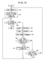
- Figure 13 is a flow chart for showing the packet recording process.
- Step S80 when the recording stream from the set top box is recorded in the hard disc HD in the information recording and reproducing apparatus SR of the embodiment, first a reference number flag showing the number of the packets PT which are recorded into the hard disc HD is initialized (Step S80). Next, the recording start position of the stream information SOB ( Figures 4 and 5) including an aligned unit ALU ( Figure 5) on the hard disc HD is obtained based on the hard disc HD and temporarily memorized into a memory (not shown) inside the microcomputer 23 on the basis of the hard disc HD in Step S81. Further, it is constantly monitored whether or not an operation of stopping a recording process according to the embodiment is operated to stop the recording process of the embodiment by the remote control section 26 (Step S82).
- Step S82 When the operation is conducted along YES in Step S82, the recording process is terminated. On the other hand, when the operation is not conducted (NO in Step S82), a piece of the packet PT, which is sent as the recording stream, is received (Step S83) . Further, the information in the received packet is recorded at a position of record in the hard disc HD (Step S84) . Then the above-mentioned reference flag is increased by "1" (Step S85) .
- Step S86 it is confirmed whether or not two consecutive event change tables DIT are detected in a case where the two event change information tables DIT are inserted into the recording stream.
- Step S86 when the two consecutive event information tables DIT are detected (YES in Step S86), a record end position of the stream information SOB on the hard disc HD is obtained on the basis of the hard disc HD and temporarily memorized on the memory inside the microcomputer 23 (Step S87) . Then the process moves to the above-mentioned Step S82 so as to receive next packet from the set top box ST.
- Step S86 when the two consecutive event change information tables are not detected (NO in Step S86), it is confirmed whether or not the value of the reference number flag showing the packet number, which is received in the one aligned unit at the present time, reaches a predetermined set number or not (Step S88).
- the process moves to the above-mentioned Step S80 so as to receive a next packet PT from the set top box ST.
- the process moves to Step S80 so as to repeat the above process for the next aligned unit ALU.
- the unit information INF shown in Figure 4 is formed in use of the unit information temporary file which is sent in the process shown in Step S60 of Figure 10, and the information is recorded into the hard disc HD along the recording format shown in Figure 4.
- Figure 14 schematically shows a relationship between the aligned unit ALU and the packet PT on the hard disc HD on the time axis after the digital information is recorded.
- the recording stream following the next packet PT is recorded from the top of the aligned unit ALU which is unrecorded.
- the event change information table is inserted after inserting a requisite number of null packets including no information so as to make the border of the packet PT in agreement with the border of the aligned unit ALU.
- the unit information temporary file when the unit information temporary file is normally received, as shown in the top end of Figure 15, it is sent in a state where the event change information table DIT is inserted at each change of content as the event in the stage of the output information Sdp which is outputted from the set top box ST.
- the third event change information table DIT on the observers left is a unit, of which EIT (abbreviation thereof is EIT and information showing an attribute and so on of each event) contained in the original TS is not obtainable by some reason when the output information Sdp is generated, and is inserted in a short time after the immediate prior event change information table (the second event information change table DIT counted from the observer's left in the top end of Figure 15) is inserted.
- EIT abbreviation thereof is EIT and information showing an attribute and so on of each event
- the value of the event reference number flags corresponding to the each event change information table DIT is "0", "1", "2" and "3" in the sequential manner from the observer's left as shown in the second column from the top on Figure 15.
- the unit information temporary file corresponding to the event reference flag "2" is not resultantly generated. Therefore, in a case shown in Figure 15, the number of the unit information temporary file which is generated in correspondence with the output information Sdp outputted from the set top box in Figure 15 are three, namely a unit information temporary file TFO corresponding to an event reference number flag "0"; a unit information temporary file TF1 corresponding to an event information reference flag "1”, and a unit information temporary file TF3 corresponding to an event information reference flag "3" as shown in the third column from the top on Figure 15.
- the mode is in a shape such that borders of aligned units ALU are respectively formed at change points of events as shown in the second column from THE top on Figure 2.
- the aligned units belonging to each of the event reference number flags form "extent", being a pack of information corresponding to the above stream information SOB in the information recorded on the hard disc HD.
- output information Sdp without a unit information temporary file TF formed therefrom, forms a garbage extent, being unnecessary information on the hard disc HD.
- the output information pieces Sdp corresponding to each of the extents respectively form the units Y on the logical format which respectively correspond to each of the events on the hard disc HD.
- Figure 16 is a flowchart for showing the recording process.
- Figures 17-18 show examples of a reproduction control screen which is displayed on a display device (not shown in Figure 3) when the output information Sdp, which is recorded onto the hard disc HD in use of the unit information INF recorded onto the hard disc HD, is reproduced.
- a file acquisition flag which shows that one file (including a unit information temporary flag, hereinafter the definition is the same) is normally received, is initialized (Step S116).
- An event counter being a parameter which increases at each receipt of one event of output information Sdp aside from the set top box ST, is initialized in the information recording and reproducing apparatus SR(Step S117).
- a unit registration flag being a parameter indicating whether or not the unit information INF is in a condition that the unit information is able to be registered onto the hard disc HD, is initialized (Step S118). Counting of the timer used for a recording clock signal or the like in the information recording and reproducing apparatus SR is started (Step S119).
- Step S120 it is confirmed whether or not an operation of stopping a recording process of the recording stream onto the hard disc is conducted in the remote control section 26 (Step S120).
- the operation is conducted (YES in Step S120)
- the process directly goes to Step S140 shown in figure 12.
- the process is not conducted (NO in Step S120)
- Step S86 when the two continuous event change tables DIT are detected (YES of Step S122), next it is confirmed whether or not the above file acquisition flag is "1"(Step S123).
- Step S123 it represents that all necessary reproduction information pieces Sdp are received without causing a packet drop to be described below.
- the unit registration flag is "1" so as to record the received file to the hard disc HD (Step S124).
- the unit registration flag is "1" (YES in Step S124)
- the unit information temporary file is read out of the received file and records thus read-out file as the unit information INF(Step S125).
- the record starting position and the record ending position are recorded (Step S126).
- the file acquisition flag is initialized (Step S127) .
- the event counter is incremented by "1" (Step S128). Then the process transfers to the above Step S118 in preparation for receipt of the next packet.
- Step S122 when two event change information tables DIT are not consecutively detected (No in Step S122), it is then checked whether or not the unit registration flag is "0" and also the above timer count exceeds two seconds (Step S129).
- Step S129 the process returns to the above Step S120 and packets are continuously received.
- the timer count exceeds two seconds the unit registration flag is rendered "1" (Step S130) and packets are continuously received after returning to the above Step S120.
- a channel selection operation for exemplifying along with a display example on a display D in Figure 17 when for example a program which is broadcasted in channel 101 is recorded for seven minutes, a program broadcasted in channel 102 is then watched for less than two seconds for selecting stations; a program broadcasted in channel 102 is then recorded for five minutes; the recording process is then temporarily ended (stopped) ; a new program which is started in the same channel 103 is then recorded for eight minutes; and a programbroadcasted in channel 141 is then recorded for 10 minutes, the unit information piece INF, which designates that the recording is done, of the program broadcasted in the above channel 102 is not recorded. Accordingly, as the result, a program "BBB" which has been broadcasted in the channel 102 is not displayed at all in the unit information INF after a series of recording information processes is completed, like the unit information on the display D shown in Figure 18.
- the threshold time of "two seconds" used in the judgment of Step S129 in Figure 16 is basically set in an arbitrary manner. More specifically, it may be possible to make a user of the information recording and reproducing apparatus SR arbitrarily set up or to set up in reference of the information amount of an information unit such as a packet on the partial TS.
- FIG. 19 is a drawing schematically showing the mode.
- the unit information temporary file TF0, TF1 and TF2 are respectively formed in correspondence with the event reference number flag, which changes at a timing of inserting each event change information table DIT in a manner similar to the case described in reference of Figure 5 (vide the uppermost column of Figure 19) .
- Step S100 an accident detecting process described below is conducted in parallel with the packet recording process (Step S80).
- Figure 20 is a flowchart showing the accident detecting process.
- Step S101 first an error possibility flag is first initialized (Step S101); then it is confirmed whether or not an operation of stopping to record a recording stream to the hard disc in the remote controller 26 (Step S102); and when if the operation is not conducted (NO in Step S102), the unit information INF is formed in use of the unit information temporary file which is sent by the process shown in Step S60 (Step S103).
- Step S104 a present value of the event counter is compared with a value of the event reference number flag corresponding to the output information which is currently received, and it is confirmed whether or not the values are equal.
- Step S107 when the current value of the event counter does not match the value of the event reference number (NO in Step S104), it is assumed that the above described drop of packet possibly occurs, and the above error possibility flag is rendered "1" (Step S107), and the process moves to the above Step S102 for waiting receipt of a next file.
- Step S104 when there is a file in which the current value of the event counter matches THE event reference number flag which is designated by the received unit information INF (Step S104), it is assumed that the output information is normally received at present, the file acquisition flag is rendered "1" (Step S105), and the received flag is recorded as the unit information temporary file on the hard disc HD onto the hard disc HD (Step S106), and the process transits to the following Step S102 for waiting receipt of the next file.
- Step S108 when an operation of stopping the recording process is instructed onto the remote controller (YES in Step S102), it is then confirmed whether or not the value of the prospect flag is "0" (Step S108).
- the value of the error possibility flag is "0"
- Step S109 the discontinuous point at a timing when the drop of packet occurs by a process such as the above-mentioned arrival time information is detected on the hard disc HD (Step S109), and the final address of the aligned unit ALU including the searched discontinuous point is recognized as a record ending position of the stream information SOB immediately before the aligned unit and a record starting position of the stream information SOB immediately after the aligned unit(Step S110), a file system, being management information, is reproduced and the process transfers to Step S140 shown in Figure 12.
- the event reference number flag and the event counter are compared, and when these values are different, it is recognized that DIT lacks and and the input information Sdp is inputted, it is possible to assuredly detect an event where the output information Sdp is inputted in a state that DIT lacks.
- the change point of the event is detected by detecting the discontinuous point of the arrival time information inside the output information, it is possible to assuredly detect the change point of the event.
- the output information is recorded onto the hard disc as-is. Therefore, a necessary information is recorded into the hard disc at a high rate.
- the programs corresponding to the flowcharts respectively shown in Figures 6 to 10 and Figures 12, 13, and 16 are recorded in the recording medium such as a flexible disk and a hard disc or through a network such as an internet.
- the programs are read out of a general-purpose CPU and conducted, such the CPU is operated as the microcomputer 3 or 23 according to the present embodiment.
Landscapes
- Engineering & Computer Science (AREA)
- Multimedia (AREA)
- Signal Processing (AREA)
- Television Signal Processing For Recording (AREA)
- Signal Processing For Digital Recording And Reproducing (AREA)
- Management Or Editing Of Information On Record Carriers (AREA)
Applications Claiming Priority (2)
| Application Number | Priority Date | Filing Date | Title |
|---|---|---|---|
| JP2003193567 | 2003-07-08 | ||
| PCT/JP2004/007929 WO2005004475A1 (ja) | 2003-07-08 | 2004-06-07 | 情報記録装置及び情報記録方法並びに情報送出装置及び情報送出方法 |
Publications (2)
| Publication Number | Publication Date |
|---|---|
| EP1643766A1 true EP1643766A1 (de) | 2006-04-05 |
| EP1643766A4 EP1643766A4 (de) | 2011-01-26 |
Family
ID=33562469
Family Applications (1)
| Application Number | Title | Priority Date | Filing Date |
|---|---|---|---|
| EP04745639A Withdrawn EP1643766A4 (de) | 2003-07-08 | 2004-06-07 | Informationsaufzeichnungseinrichtung, informationsaufzeichnungsverfahren, informationübertragungseinrichtung und informationsübertragungsverfahren |
Country Status (6)
| Country | Link |
|---|---|
| US (1) | US20060159418A1 (de) |
| EP (1) | EP1643766A4 (de) |
| JP (1) | JP4194601B2 (de) |
| KR (1) | KR20060028806A (de) |
| CN (1) | CN1820502A (de) |
| WO (1) | WO2005004475A1 (de) |
Cited By (1)
| Publication number | Priority date | Publication date | Assignee | Title |
|---|---|---|---|---|
| EP1950962A1 (de) * | 2005-10-27 | 2008-07-30 | Matsushita Electric Industrial Co., Ltd. | Transportstromerzeugungsvorrichtung, aufzeichnungsvorrichtung damit und transportstromerzeugungsverfahren |
Families Citing this family (1)
| Publication number | Priority date | Publication date | Assignee | Title |
|---|---|---|---|---|
| CN101713625B (zh) * | 2009-08-14 | 2011-09-21 | 江苏省鑫通阀门制造有限公司 | 组合式螺纹量规 |
Citations (2)
| Publication number | Priority date | Publication date | Assignee | Title |
|---|---|---|---|---|
| EP1021048A2 (de) * | 1999-01-14 | 2000-07-19 | Kabushiki Kaisha Toshiba | System zur Aufnahme von digitalem Video und Aufnahmemedium |
| EP1102275A2 (de) * | 1999-11-12 | 2001-05-23 | Matsushita Electric Industrial Co., Ltd. | Aufzeichnungsgerät und Programmaufzeichnungsmedium |
Family Cites Families (3)
| Publication number | Priority date | Publication date | Assignee | Title |
|---|---|---|---|---|
| EP2146499B1 (de) * | 1997-11-14 | 2012-10-31 | Sony Deutschland Gmbh | Verteilung von MPEG-2-Transportströmen über IEEE 1394-Hausnetzwerk |
| JP2001086440A (ja) * | 1999-09-13 | 2001-03-30 | Toshiba Corp | ディジタル放送復号再生装置及びディジタル放送受信端末装置 |
| GB0007868D0 (en) * | 2000-03-31 | 2000-05-17 | Koninkl Philips Electronics Nv | Methods and apparatus for editing digital video recordings and recordings made by such methods |
-
2004
- 2004-06-07 CN CNA2004800195485A patent/CN1820502A/zh active Pending
- 2004-06-07 EP EP04745639A patent/EP1643766A4/de not_active Withdrawn
- 2004-06-07 JP JP2005511312A patent/JP4194601B2/ja not_active Expired - Fee Related
- 2004-06-07 WO PCT/JP2004/007929 patent/WO2005004475A1/ja active Application Filing
- 2004-06-07 KR KR1020067000031A patent/KR20060028806A/ko not_active Application Discontinuation
- 2004-06-07 US US10/563,251 patent/US20060159418A1/en not_active Abandoned
Patent Citations (2)
| Publication number | Priority date | Publication date | Assignee | Title |
|---|---|---|---|---|
| EP1021048A2 (de) * | 1999-01-14 | 2000-07-19 | Kabushiki Kaisha Toshiba | System zur Aufnahme von digitalem Video und Aufnahmemedium |
| EP1102275A2 (de) * | 1999-11-12 | 2001-05-23 | Matsushita Electric Industrial Co., Ltd. | Aufzeichnungsgerät und Programmaufzeichnungsmedium |
Non-Patent Citations (1)
| Title |
|---|
| See also references of WO2005004475A1 * |
Cited By (2)
| Publication number | Priority date | Publication date | Assignee | Title |
|---|---|---|---|---|
| EP1950962A1 (de) * | 2005-10-27 | 2008-07-30 | Matsushita Electric Industrial Co., Ltd. | Transportstromerzeugungsvorrichtung, aufzeichnungsvorrichtung damit und transportstromerzeugungsverfahren |
| EP1950962A4 (de) * | 2005-10-27 | 2010-02-03 | Panasonic Corp | Transportstromerzeugungsvorrichtung, aufzeichnungsvorrichtung damit und transportstromerzeugungsverfahren |
Also Published As
| Publication number | Publication date |
|---|---|
| US20060159418A1 (en) | 2006-07-20 |
| CN1820502A (zh) | 2006-08-16 |
| JPWO2005004475A1 (ja) | 2006-08-17 |
| WO2005004475A1 (ja) | 2005-01-13 |
| EP1643766A4 (de) | 2011-01-26 |
| JP4194601B2 (ja) | 2008-12-10 |
| KR20060028806A (ko) | 2006-04-03 |
Similar Documents
| Publication | Publication Date | Title |
|---|---|---|
| US8606081B2 (en) | Stream data recording device, stream data recording/reproducing device, stream data reproduction device, stream data editing device, stream recording method, and stream reproducing method | |
| EP2329654B1 (de) | Vorrichtungen für digitalen videoempfang und -ausgang mit fehlererkennungs- und verdeckungsschaltung sowie verfahren | |
| KR20000031860A (ko) | 디지털 데이터 스트림 기록방법 및 그 장치 | |
| US20050125825A1 (en) | Broadcast system, recording device, recording method, program, and recording medium | |
| US20040060076A1 (en) | Method and apparatus for preventing duplicate recording of a broadcasting program | |
| US8195030B2 (en) | Reproduction apparatus, reproduction method, recording apparatus, recording method, AV data switching method, output apparatus, and input apparatus | |
| US20020006273A1 (en) | High-density recording medium having data format acceptable to a digital television and a data reproducing apparatus thereof | |
| US5895123A (en) | Information recording/reproduction apparatus for reproducing picture and audio signals in synchronization | |
| KR100405975B1 (ko) | Pvr에서의 스트림 점프 방법 | |
| JP2006270299A (ja) | Cm検出装置およびcm検出方法 | |
| US20060269255A1 (en) | Recording and reproducing apparatus, MPEG image stream recording and reproducing apparatus and medium | |
| US8380038B2 (en) | Broadcasting station apparatus and recording/reproducing apparatus | |
| EP1643766A1 (de) | Informationsaufzeichnungseinrichtung, informationsaufzeichnungsverfahren, informationübertragungseinrichtung und informationsübertragungsverfahren | |
| US8254764B2 (en) | Recording apparatus, image reproducing apparatus, and special reproduction method therefor | |
| US20060271994A1 (en) | Information output device and information output method, information recording device and information recording method, information output program and information recording program, and information recording medium | |
| US20040081436A1 (en) | Data recording apparatus, data reproduction apparatus, data recording program, data reproduction program, recording medium and data recording medium | |
| CN101981926A (zh) | 数字广播发送器、数字广播接收器及其方法 | |
| JP2005184093A (ja) | 番組録画再生システム、番組録画再生サーバ、番組受信端末及び番組表生成方法 | |
| KR100914706B1 (ko) | 방송 수신기 및 장면 정보 수신 방법 | |
| JP3534710B2 (ja) | デジタル放送受信システム | |
| WO2005004155A1 (ja) | 情報記録装置及び情報記録方法 | |
| CN101175167A (zh) | 检测电视节目转换的设备及方法 | |
| JP2003143544A (ja) | デジタル放送受信装置 | |
| JP2000312340A (ja) | デジタル情報信号記録方法、デジタル情報信号記録装置、及びデジタル情報信号記録媒体 | |
| JP2000023093A (ja) | 映像識別信号の附加及び削除装置及びその方法 |
Legal Events
| Date | Code | Title | Description |
|---|---|---|---|
| PUAI | Public reference made under article 153(3) epc to a published international application that has entered the european phase |
Free format text: ORIGINAL CODE: 0009012 |
|
| 17P | Request for examination filed |
Effective date: 20060104 |
|
| AK | Designated contracting states |
Kind code of ref document: A1 Designated state(s): DE FR GB |
|
| DAX | Request for extension of the european patent (deleted) | ||
| RBV | Designated contracting states (corrected) |
Designated state(s): DE FR GB |
|
| RAP1 | Party data changed (applicant data changed or rights of an application transferred) |
Owner name: PIONEER CORPORATION |
|
| A4 | Supplementary search report drawn up and despatched |
Effective date: 20101223 |
|
| STAA | Information on the status of an ep patent application or granted ep patent |
Free format text: STATUS: THE APPLICATION IS DEEMED TO BE WITHDRAWN |
|
| 18D | Application deemed to be withdrawn |
Effective date: 20110103 |