EP1643537A2 - Dielectric barrier discharge lamp with plug-in electrodes - Google Patents
Dielectric barrier discharge lamp with plug-in electrodes Download PDFInfo
- Publication number
- EP1643537A2 EP1643537A2 EP05018817A EP05018817A EP1643537A2 EP 1643537 A2 EP1643537 A2 EP 1643537A2 EP 05018817 A EP05018817 A EP 05018817A EP 05018817 A EP05018817 A EP 05018817A EP 1643537 A2 EP1643537 A2 EP 1643537A2
- Authority
- EP
- European Patent Office
- Prior art keywords
- discharge
- electrodes
- discharge lamp
- discharge vessel
- plug connection
- Prior art date
- Legal status (The legal status is an assumption and is not a legal conclusion. Google has not performed a legal analysis and makes no representation as to the accuracy of the status listed.)
- Withdrawn
Links
Images


Classifications
-
- H—ELECTRICITY
- H01—ELECTRIC ELEMENTS
- H01J—ELECTRIC DISCHARGE TUBES OR DISCHARGE LAMPS
- H01J65/00—Lamps without any electrode inside the vessel; Lamps with at least one main electrode outside the vessel
- H01J65/04—Lamps in which a gas filling is excited to luminesce by an external electromagnetic field or by external corpuscular radiation, e.g. for indicating plasma display panels
- H01J65/042—Lamps in which a gas filling is excited to luminesce by an external electromagnetic field or by external corpuscular radiation, e.g. for indicating plasma display panels by an external electromagnetic field
- H01J65/046—Lamps in which a gas filling is excited to luminesce by an external electromagnetic field or by external corpuscular radiation, e.g. for indicating plasma display panels by an external electromagnetic field the field being produced by using capacitive means around the vessel
Definitions
- the present invention relates to a dielectrically impeded discharge lamp.
- This is understood to mean discharge lamps in which at least the anodes or, in the case of bipolar operation, also all electrodes are separated by a dielectric layer from a discharge medium in the discharge vessel.
- an autonomous extinction of the discharge by an internal counterpolarization occurs.
- the lamp operation is thus ultimately by a dense series of very short discharge flashes.
- Such dielectrically impeded discharge lamps have been variously known in the art and, due to various advantageous technical characteristics, are of particular interest for the backlighting of display devices, such as computer monitors and television screens, or for office automation applications.
- elongated rod-shaped lamp shapes are generally used, which can be used to illuminate documents in scanners, fax machines, copiers and the like.
- Such discharge lamps with a tubular elongate discharge vessel are also already known and available. You can also use it for other applications, for example as a UV emitter for certain technical processes, be of interest.
- the present invention is not limited to any particular application.
- Dielectrically impeded discharge lamps can not be operated with direct current due to the short outlined discharge mechanism, but are operated either with unipolar power supply pulses or with bipolar power supply pulses.
- the frequencies used are usually in the order of some 10 kHz.
- the described tubular elongated discharge lamps have electrodes oriented along the longitudinal extent. This does not necessarily mean that the electrodes must run as simple straight strips parallel to the direction of longitudinal extension. They can also be meandering or structured in a different form, but run overall along the longitudinal extent.
- the invention relates to discharge lamps in which at least two electrodes outside the discharge vessel, d. H. on the outside, are attached. In the prior art, both types with internal electrodes and those with external electrodes are known. External electrodes provide i. d. R. simpler production, but force certain minimum thicknesses of the dielectric layer between the electrode and the discharge medium, because the discharge vessel wall itself serves as such
- the electrodes are usually contacted by soldering or so-called crimp connections.
- the contact is made to cables that connect to a ballast for operating the discharge lamp.
- the invention is based on the technical problem of specifying a dielectrically impeded discharge lamp with at least two external electrodes, which can be contacted in an advantageous manner.
- the invention should specify a corresponding lighting system with such a lamp and a suitable ballast and a method for contacting the discharge lamp.
- the technical problem is solved by a dielectrically impeded discharge lamp, in which the electrodes are rod-shaped and formed at one end as a plug connection element.
- the invention is also directed to a lighting system with such a discharge lamp and with an electronic ballast for operating the lamp, with a housing of the ballast, a connector element is firmly connected, which is designed so that the lamp with the contacts having the end complementary plug connection element can be connected by mating with the connector element of the housing to the ballast.
- the invention is also directed to a method for contacting the discharge lamp, in which in each case one end of the rod-shaped electrodes plugged together as a plug connection element with a complementary counter-plug connection element and the discharge lamp is thus electrically connected.
- rod-shaped means that the electrodes have a certain inherent dimensional stability and can therefore be used as a plug connection element, ie are not foil electrodes.
- the length and width of the electrodes should be comparable transversely to the longitudinal extent of the order of magnitude, for example not differing by more than a factor of 5 from one another.
- the electrodes should be designed so that they are in a mechanically preferably detachable, d. H. can be separated again without fundamental destruction, form can be connected to a complementary connector element.
- a plug-in connection is understood to mean a frictional connection of largely inherently stable elements taking place while retaining the essential shape of the plug connection elements.
- the connector is to be demarcated from, for example, crimp, in which foil-like electrodes are contacted in a significant change in their shape and without taking advantage of dimensional stability.
- the electrodes may be simple round rods and either have a pipe end as a so-called female element of the plug connection or terminate as a so-called male element as a round rod.
- the trained for receiving a round rod tube end as a female connector element can thus be present both on the electrode side and cable or ballast side.
- the round cross-sectional shape is preferred.
- a further embodiment provides to increase the contact area between the electrodes, for example the mentioned round bars, and the discharge vessel by bridging and thus widening the contact surface with a conductive flowable substance.
- this substance may also be a conductive adhesive.
- a particular embodiment also provides that the electrodes are not, as usual, made of a metal, but of a conductive and to some extent deformable plastic.
- the elasticity of this plastic can on the one hand widen the contact surface on the discharge vessel and on the other facilitate the production of the connector.
- metallic electrodes are also preferred.
- a further embodiment of the invention provides that the electrodes are attached to the discharge vessel by positive engagement with a cuff enclosing the electrodes, which cuff partially surrounds the circumference of the discharge vessel perpendicular to the longitudinal extent, while leaving an aperture for light emission free.
- This also relates to a corresponding production method, in which the electrodes are attached to a tubular elongate discharge vessel by a positive engagement with a cuff enclosing the electrodes such that the electrodes lie along the longitudinal extent of the discharge vessel, the cuff leaving an aperture open for light emission.
- Cuff is here referred to a device that has its own sufficient dimensional stability to hold the electrodes by positive engagement.
- the cuff should therefore be used as a kind of clamp or clamping device. This allows to release an aperture for light emission by the discharge lamp, so that the cuff does not have to be made particularly thin and not transparent.
- the cuff must also not be glued on. It also allows stabilization and / or protection of the discharge vessel against external influences and can thus also to a desired weight reasons and to avoid high voltages reduction of the wall thicknesses of the discharge vessel contribute.
- the electrodes can be mounted on the discharge vessel by simply clipping on or pushing in or into the sleeve, so that the production of the discharge lamp at this point is significantly simplified and accelerated.
- the electrodes are not yet adhesively bonded or otherwise fastened to the discharge vessel, and further that the sleeve is biased for this purpose, ie also in the mounted state still maintains a certain contact pressure.
- the sleeve itself is held on the discharge vessel only by form-fitting or frictional connection as a result of its intrinsic stability, that is, it rests freely on itself. So you should also not be glued additionally.
- the sleeve extends substantially along the entire discharge vessel. It can also be used in one case, one or a plurality of sleeves, which make up only part of the longitudinal extent of the discharge vessel.
- the above explanation of the positive locking and the inherent dimensional stability of the sleeve is not to be understood as necessarily having to be in one piece. It is provided in the context of a particular embodiment of the invention, on the contrary, to use an at least two-part cuff. In this case, a functional differentiation can take place, for example in the form of an outer shielding plate and an electrical insulation located therein between the electrodes and the shielding plate. In such cases, the insulation itself may not necessarily be dimensionally stable, although it should be considered part of the cuff.
- Another possibility for a two-part cuff consists in two along the longitudinal extent of the discharge vessel divided and in the assembled state adjoining and firmly connected parts that produce a positive or non-positive connection in the connected state relative to the discharge vessel. Such parts can therefore also be applied without form and force fit to the discharge vessel and then connected to produce the positive or non-positive connection.
- Particularly suitable are clip connections between the two parts, preferably also non-detachable clip connections.
- This embodiment is particularly suitable for sleeves, which consist of not substantially elastic material.
- a further embodiment of the invention provides for a modular arrangement of individual discharge vessels, which can be operated together as a quasi-uniform discharge lamp.
- the electrodes of the individual modules can be plugged together and the cuffs of individual modules could also be connected to each other or configured only adjacent to one another, however, it would also be possible to use a continuous cuff for a plurality of modules.
- this embodiment may be advantageous, for example when the discharge vessels are modularly arranged in the manner described modular and are held by modular or continuous sleeves and thereby continuous external electrodes in the manner according to the invention by the sleeve (s) are held.
- the frequencies used during operation of the discharge lamp are generally of the order of a few 10 kHz, so that such discharge lamps generate interference radiation in EMC-sensitive environments.
- This problem can advantageously be solved by a conductive metallic shield which partially surrounds the discharge vessel and thereby leaves open an opening angle for the emission of light, wherein at least one of the opening angle limiting screen surface of the shield of the discharge vessel is at its outermost end by a distance which is at least as large as half the average diameter of the discharge vessel transversely to the longitudinal extent.
- Tubular discharge lamps of this type have a so-called aperture along their longitudinal extension, that is to say a longitudinal strip from which light emerges from the lamp.
- this aperture should preferably not be covered directly by a shield, which is why known shields completely eliminate the aperture.
- the lamp then radiates over the entire recessed area in the corresponding solid angle.
- the screen surface provided by the invention limits the solid angle of this radiation and thus also defines an opening angle of the light emission.
- This opening angle can be optimized for the technically desired application, d. H. in individual cases, the opening angle can also be significantly smaller than actually possible with a given aperture. In this case, however, the shielding surface would not affect the luminous efficacy at the relevant spatial angle for the application, but would significantly improve the shielding.
- the shield is not limited to a known conductive sheath of the discharge vessel outside the opening angle, but rather that the shield has at least one shield surface which extends away from the discharge vessel and thereby limits the opening angle.
- the shield should therefore, so to speak, have a "diaphragm" along at least one lateral boundary of the opening angle.
- corresponding shielding surfaces are provided at both boundaries of the opening angle, but a shielding surface could also be dispensed with, for example if the shielding in the other direction is not essential or has already been given for other reasons, for example by a metallic wall which is present anyway is.
- the shielding surface does not necessarily have to run along its entire extent along the boundary of the opening angle, that is, does not necessarily extend essentially radially.
- at least its extreme end limits the opening angle.
- this outermost end is removed from the discharge vessel by at least half the mean diameter of the discharge vessel.
- the shield it is also not absolutely necessary for the shield to surround the entire remaining circumference of the discharge vessel apart from the opening angle. Again, by insignificance of EMI radiation in a particular direction or shielding elements provided there anyway, the reasons for a shield missing and / or other structural reasons may be given, which make a gap in the shield appear advantageous.
- the shield surrounds and shields the discharge vessel by more than half of its circumference and thus preferably forms the already described sleeve.
- This cuff can, as explained in more detail below, also have advantageous properties as an assembly aid or holder.
- the cuff mentioned preferably has a portion of the circumference of the discharge vessel, more preferably the remainder of the screen area, a relatively small distance from the discharge vessel, in proportion to the mean half diameter of the discharge vessel.
- the remaining part of the shield then forms the aforementioned screen surface.
- the shielding surface according to the invention of the shield can limit the light emission of the lamp and thus define an effective opening angle at least to one side.
- the extent of the aperture to the center of the discharge vessel in the cross section to the longitudinal direction and considers this as the opening angle, preferably the light emission opening angle of the shield at the same center point should be greater than that of the aperture.
- the shielding surface can indeed dim the light emitted by the aperture because the light emission in the lamp also takes place from the aperture closer parts of the inner shell, so that the effective light emission angle of the aperture is greater than the radially considered opening angle.
- the shield can also contain other shielding elements in the region of the opening angle in addition to the shielding surface (s), in particular planar shielding parts extending essentially radially in cross section, which further subdivide the opening angle.
- the shield can also be slightly improved in the direction of the light emission. Examples are explained below.
- the sleeve if it is electrically conductive or contains electrically conductive parts, not too strong capacitive coupling to the electrode (s). If, in the following, the conductive part of the sleeve is turned off, that is to say, for example, the aforementioned shielding plate, it is preferred that an assumed radial thickness d D between the metallic sleeve and the outer electrode, that is to say the thickness of the mentioned insulation layer within the metal shield , and a dielectric constant ⁇ D of this layer as well as a thickness d B of the dielectric barrier between the electrode and the discharge medium with a corresponding relative permittivity ⁇ B overall satisfy the relationship: d D / ⁇ D ⁇ F ⁇ d B / ⁇ B .
- factor F is at least 1.5, preferably at least 2 and more preferably at least 2.5.
- EP 0 981 831 also explains, inter alia, that in this regard, in the case of multilayer structures, the corresponding sum of the individual quotients of thickness and dielectric constant must be used.
- a simple and preferred possibility is to provide at least one, preferably two end base on the lamp, which are dimensioned radially slightly larger than the discharge vessel itself. Then when the shield applied in an adjacent manner to the base and preferably also mounted in this form and is held, is given by the radial difference between the base and discharge vessel of the desired distance.
- a further preferred embodiment of the base relates to flats on its cross-sectional shape (perpendicular to the longitudinal extent of the discharge vessel), which are provided in a suitable manner to the shield, such as a correspondingly shaped metal sheet. Then, when the shield is mounted on the pedestals, the orientation of the flattenings allows a correct orientation, that is to say in particular an alignment of an aperture of the lamp, to the opening angle defined by the shield.
- the base may also include other locking devices that match the shield. However, it can also alone by the cuff shape, d. H. be given by the positive connection of the shield itself, a locking or clamping action.
- the invention also relates to such discharge lamps, in which the at least two counter-plug connection elements for the described electrode ends are included, which are therefore already provided for example with a cable or packed together with it. Preference is given not only a nondestructive releasable connector, but also a producible via purely translational movement connector. Such connectors are structurally simple and allow a particularly simple contacting method.
- the plug connection elements on the electrodes or the complementary plug connection elements are designed such that an element at least partially surrounds the complementary one.
- the rod end is completely encompassed by the pipe end.
- the flat end is only on two sides, that is only partially encompassed by the complementary element.
- the electrode ends to be used as plug-in connection elements project beyond the discharge lamp and are therefore particularly easy to reach for connection to the complementary plug connection elements.
- This embodiment proves itself particularly in connection with the embodiments explained below.
- the invention relates to a lighting system with the discharge lamp, in which a connector element is fixedly connected to a housing of the ballast, which is designed so that the lamp with the end having the electrode ends as contacts by plugging together as a complementary connector element can be connected to the ballast with the connector element of the housing.
- the discharge tube with tubular elongated discharge vessel itself
- the discharge lamp at one end to the illustrated electrode ends for electrical connection and is connected at this end with a suitably designed complementary connector element, which is firmly connected to the ballast, ie the housing.
- the ballast-side connector element may be connected via a cable to a circuit board of the ballast, but should be created by the connector, a direct mechanical connection between the lamp and ballast.
- the ballast-side connector element not only fixed to the housing, but is integrated into the housing.
- the connector element should not be a solid attachment. It should therefore be dispensed with a flexible cable between the ballast housing and the lamp in the sense of a flexible mechanical connection between them.
- the connector element is integrally integrated in the ballast housing, so for example as a recess in a remotely z. B. cuboid housing, in which recess the tubular lamp itself can be inserted with one end.
- the exemplary embodiment For the sake of illustration, reference is made to the exemplary embodiment.
- the ballast-side connector element is preferably a socket, so a female element with respect to the tubular shape of the lamp.
- Preferred applications of the discharge lamp according to the invention and the illumination system according to the invention are not only in office automation, but also in UV lamps. Such UV lamps can be used for various technical processes. Of particular interest in the context of this invention is the illumination of catalyst surfaces for photocatalysis of reactions.
- a preferred example of an application is in air purification, especially in vehicles, such as Motor vehicles.
- air pollutants can be converted by a photocatalytic process and thus eliminated and thus the vehicle interior are supplied with a relation to the outside world qualitatively much improved air.
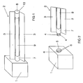
- FIG. 1 of the present application shows an inventive lighting system with an electronic ballast 1, which is shown here as a simple cuboid.
- the figure shows only the housing of the ballast 1, which contains the otherwise known per se circuit parts of a ballast for operating a dielectrically impeded discharge lamp. This may in particular be a class E converter.
- FIG. 1 shows that in the rear region of the right side of the ballast 1 in FIG. 1, a substantially line-shaped dielectrically impeded discharge lamp 2 with two laterally projecting shielding surfaces 3 is inserted.
- Figure 2 shows a detail of the ballast 1 and the lamp 2 of Figure 1 is a situation in which the lamp 2 is pulled out of the ballast 1.
- FIG. 3 shows a plan view of the situation from FIG. 1.
- FIG. 2 It can be seen in FIG. 2 that a base 7 of the tubular lamp 2 projects beyond the shielding surfaces 3 to the left and this cylindrical protruding one Base 7 has three further reaching axially extending electrode ends 4. Further, Figure 2 indicates that the ballast 1 in its right side surface of the otherwise cuboidal housing shape has a matching receptacle receptacle 5 with therein provided female connector elements 6 for the mentioned axial electrode ends 4 of the discharge lamp 2.
- the axial electrode ends 4 are left-hand ends of round-rod-shaped electrodes of the lamp 2 in FIGS. 1 to 3, to which reference will be made in greater detail with reference to FIGS. 4 to 9. These electrode ends are inserted according to FIG. 2 together with the base 7 of the discharge lamp 2 projecting beyond the shield surfaces 3 into the described socket 5 with the plug connection elements 6. As a result, as shown in FIGS. 1 and 3, the lamp 2 is not only electrically connected to the ballast 1, but moreover is also firmly mounted on it. The ballast 1 thus serves as a lamp holder. A flexible cable between the lamp 2 and ballast 1 can therefore be omitted.
- the part of the lamp 2 extending beyond the shielding surfaces 3 is a plastic base 7 which, together with a second base 8 recognizable in FIGS. 1 and 3, is a tubular glass discharge vessel 9 in a shielding plate having the shielding surfaces 3 and described in more detail below 10 stops.
- the shielding plate 10 is electrically conductively connected to the shielding surfaces 3 with the metallic housing of the ballast 1. This can be done for example by a small pin, not shown in Figures 1 and 2, which rests on the outer periphery of the base 7 and is inserted with this in the socket 5.
- the shielding plate 10 is insulated with respect to the electrodes with the ends 4 via an insulation layer (not shown here but shown in FIG. 4). This is a plastic layer. This plastic insulation lies in the visible in Figures 1 - 3 part of the discharge vessel 9 between the screening surfaces 3, namely the aperture for light emission, not in front.
- the shielding plate 10 forms with the sockets 7 and 8 a sleeve.
- FIG. 4a shows a variant of the mentioned plastic insulation, in the form of a base 11 extending over the lamp length, and otherwise electrode ends 12, which for one do not extend beyond the base 11, and which for the other have tubular shapes. These are female plug connection elements at the electrode ends in contrast to the male connector elements in Figure 2. Accordingly, a not shown complementary ballast male connector elements in a socket comparable to the socket 5 of Figure 2.
- the electrodes are inserted into matching recesses of the base 11 and are held by him form-fitting manner on the discharge vessel.
- the pedestal 11 runs over the lamp length and merges into the pedestal (8 in Figures 1 and 3) at the opposite end of the lamp. He is biased by the shield 10 against the discharge vessel 9 and holds it without further action.
- the discharge vessel 9 is thus a simple gas-filled tube with inner phosphor and reflection layers.
- the insulating layer between the electrodes and the shielding plate 10 is formed at the same time as a base corresponding to the base 7 of Figure 2, so the socket does not engage around the entire circumference of the discharge vessel end around.
- FIG. 4b shows a variant of FIG. 4a in which additional flattenings 13 are provided on the lateral regions of the base 11. These Flattened portions 13 are provided in complementary form on a shielding plate 10 (not illustrated here) corresponding to FIGS. 1-3, so that a correct alignment of the aperture with the shielding surfaces 3 can already be achieved.
- the base 7 of Figure 2 may also be configured so that it specifies only at the ends of the discharge vessel 9 a corresponding Abstandsjustage to the shielding plate 10 and the insulation in the axial intermediate region is only loosely inserted.
- the plug connection between the discharge lamp 2 and the ballast 1 shown in FIGS. 1-3 is not obligatory in the invention. Trained as plug-in elements electrode ends can be useful without this feature, for example, if instead of the socket 5 of the ballast 1, a corresponding female connector head of a connecting cable is provided to the electrode ends and optionally similar to the socket 5 to the base 7 and the discharge vessel 9 fits.
- FIGS. 5-9 show some variants of the discharge lamps according to FIGS. 1-4b.
- FIG. 5 instead of three electrodes (or electrode ends) 4, as in FIG. 2, only two electrodes 4 are provided here. Both variants are possible. Occasionally, three electrodes are chosen for better light output. For the present invention, these differences are not of particular concern.
- the opening angle between the screen surfaces 3, so the wing-like ends of the sleeve 10 is chosen here slightly smaller. However, this opening angle is still so great that it does not appreciably obstruct the actual light emission from the aperture in the upper region of the section shown in FIG. Nevertheless, these screen surfaces 3 serve to improve the electromagnetic shielding in the lateral direction by leakage fields emerging from the aperture.
- FIG. 5 illustrates the aperture in that a phosphor layer 14 is shown there, which is interrupted in the region of the aperture.
- FIG. 6 again shows three electrodes 4, but the essential difference consists in the fact that the shield surfaces 3 'from FIG. 6 are supplemented here by inwardly angled parts and thus limit an even narrower opening angle. This is still significantly larger than the aperture angle of the aperture relative to the center of the circle of the discharge vessel. However, since also the edge regions of the phosphor layer 14 emit light, the outermost regions of the light emission are already dimmed. The shielding effect is, however, improved accordingly.
- FIG. 1 has already made clear that the shielding plate 10 not only serves to hold the electrodes on the discharge vessel 9, but also stabilizes the assembly of the entire discharge lamp 2 on the ballast 1.
- the shielding surfaces 3 can also be mounted separately, for example, clamped to the ballast 1, plugged or screwed. Incidentally, they can also have an assembly function with respect to components other than the ballast housing.
- FIG. 7 shows a further variant of FIG. 5 with a further narrowed opening angle of the shielding surfaces 3, but here with straight shielding surfaces 3.
- the base 7 according to FIG. 2 runs around the entire circumference of the discharge vessel 9 and does not save, as in FIG , the aperture off.
- the base 7 is only attached to the outermost edge, this does not disturb the light emission or hardly.
- Figure 8 differs just by this latter feature of Figure 7. Again, the aperture is recessed. It is therefore a base 11 according to FIG. 4.
- FIG. 9 differs from FIG. 8 by an additional shielding part 15 in the opening angle of both the shielding surfaces 3 and the aperture.
- This is configured radially in the illustrated cross-section and otherwise planar and in the perspective view in Figure 10 better visible. It slightly reduces the light emission through the aperture, but additionally improves the electromagnetic shielding in the light emission direction.
- Such a part 15 may be a cost effective alternative or additional measure to a transparent conductive coating of the aperture, as shown in the already cited EP-font. For clarity, the details of the connector in Figure 10 are omitted.
- FIG. 11 shows, in a representation similar to FIG. 10, a variant of the design of the shielding plate 10.
- the shielding plate 10 with the shielding surfaces when viewed in section basically consists of two concentric semicircles 16 and 17 with substantially different diameters around the center of the circle of the section through the discharge vessel 9
- the semicircles 16, 17 face each other with their openings.
- the smaller of the semicircles 16 also shows a significantly greater distance from the discharge vessel 9, which is not shown here.
- the smaller semicircle 16 serves as a reflector, reflecting the light radiated from the aperture into it (that is, to the right in FIG. 11) into the larger semicircle 17, which in turn reflects the light out of the cuff.
- This variant offers a significantly poorer light output than the previous examples, but shows a much better EMC shielding.
- FIG. 12 corresponds in the illustration to FIGS. 5 to 9, but shows an exemplary embodiment without shielding plate.
- the sleeve is designed as a positive and non-positive plastic sleeve 18, which has corresponding mold recesses for the electrodes 4 and thus holds them on the discharge vessel 9.
- the shielding effect explained above is omitted here or could be given by a shield plate without screens; however, the other benefits of the cuff are also given.
- FIG. 13 shows another form 19 of such a sleeve, which is also considerably more solid. It could for example be used for mounting in a corner situation and has matching inclined surfaces with each other right angle, which are designated 20.
- FIGS. 14 and 15 show similar variants as in FIG. 13, but with an almost square cross-section of the sleeve 21 and with two in FIG. 14 and three electrodes 4 in FIG.
- FIG. 16 shows a two-part variant of a cuff.
- Both parts 22a and 22b together result in a similar cross-sectional shape as the sleeve 21 of Figures 14 and 15, but neither of the two halves already produces a positive connection or adhesion.
- the two parts are thus applied from left and right to the discharge vessel 9 and then clipped together via a preferably non-detachable clip connection in the slot 23 and so brought opposite to the discharge vessel 9 to bias.
- other cross-sectional shapes can be produced with comparable embodiments, in particular those as in the other embodiments.
- FIG. 16 also illustrates that the electrodes, designated here by 24, can also have other than round cross-sectional shapes.
Abstract
Description
Die vorliegende Erfindung bezieht sich auf eine dielektrisch behinderte Entladungslampe. Darunter versteht man Entladungslampen, bei denen zumindest die Anoden oder bei bipolarem Betrieb auch sämtliche Elektroden durch eine dielektrische Schicht von einem Entladungsmedium in dem Entladungsgefäß getrennt sind. Dadurch kommt es in Folge einer elektrischen Aufladung der dielektrischen Schicht auf der Anode bzw. der in dieser Phase als Anode wirkenden Elektrode zu einem eigenständigen Erlöschen der Entladung durch eine innere Gegenpolarisation. Der Lampenbetrieb erfolgt also letztlich durch eine dichte Reihe sehr kurzer Entladungsblitze.The present invention relates to a dielectrically impeded discharge lamp. This is understood to mean discharge lamps in which at least the anodes or, in the case of bipolar operation, also all electrodes are separated by a dielectric layer from a discharge medium in the discharge vessel. As a result, as a result of an electrical charge of the dielectric layer on the anode or the electrode acting as an anode in this phase, an autonomous extinction of the discharge by an internal counterpolarization occurs. The lamp operation is thus ultimately by a dense series of very short discharge flashes.
Solche dielektrisch behinderte Entladungslampen sind in verschiedener Weise im Stand der Technik bekannt geworden und aufgrund verschiedener vorteilhafter technischer Eigenschaften insbesondere für die Hinterieuchtung von Anzeigevorrichtungen, etwa Computermonitoren und Fernsehbildschirmen, oder für Büroautomationsanwendungen von Interesse. Im letztgenannten Fall werden i. d. R. langgestreckt stabförmige Lampenformen eingesetzt, die zur Beleuchtung von Dokumenten in Scannern, Faxgeräten, Kopierern und dgl. dienen können. Solche Entladungslampen mit einem röhrenförmig langgestreckten Entladungsgefäß sind ebenfalls bereits bekannt und erhältlich. Sie können auch für andere Anwendungen, beispielsweise als UV-Strahler für bestimmte technische Prozesse, von Interesse sein. Die vorliegende Erfindung ist nicht auf einen bestimmten Ariwendungsfall eingeschränkt.Such dielectrically impeded discharge lamps have been variously known in the art and, due to various advantageous technical characteristics, are of particular interest for the backlighting of display devices, such as computer monitors and television screens, or for office automation applications. In the latter case, elongated rod-shaped lamp shapes are generally used, which can be used to illuminate documents in scanners, fax machines, copiers and the like. Such discharge lamps with a tubular elongate discharge vessel are also already known and available. You can also use it for other applications, for example as a UV emitter for certain technical processes, be of interest. The present invention is not limited to any particular application.
Dielektrisch behinderte Entladungslampen können aufgrund des kurz umrissenen Entladungsmechanismus nicht mit Gleichstrom betrieben werden, sondern werden entweder mit unipolaren Leistungsversorgungspulsen oder mit bipolaren Leistungsversorgungspulsen betrieben. Die verwendeten Frequenzen liegen im Regelfall in der Größenordnung einiger 10 kHz.Dielectrically impeded discharge lamps can not be operated with direct current due to the short outlined discharge mechanism, but are operated either with unipolar power supply pulses or with bipolar power supply pulses. The frequencies used are usually in the order of some 10 kHz.
Die beschriebenen röhrenförmig langgestreckten Entladungslampen weisen entlang der Längserstreckung orientierte Elektroden auf. Hiermit ist nicht notwendigerweise gemeint, dass die Elektroden als einfache gerade Streifen parallel zur Längserstreckungsrichtung verlaufen müssen. Sie können auch mäandrierend oder in anderer Form strukturiert ausgebildet sein, dabei aber insgesamt entlang der Längserstreckung laufen. Die Erfindung bezieht sich auf Entladungslampen bei denen zumindest zwei Elektroden außerhalb des Entladungsgefäßes, d. h. an dessen Außenseite, angebracht sind. Im Stand der Technik sind sowohl Bauformen mit innenliegenden Elektroden als auch solche mit außenliegenden Elektroden bekannt. Außenliegende Elektroden bieten i. d. R. eine einfachere Herstellung, zwingen aber zu gewissen Mindeststärken der dielektrischen Schicht zwischen Elektrode und Entladungsmedium, weil die Entladungsgefäßwand selbst als solche dientThe described tubular elongated discharge lamps have electrodes oriented along the longitudinal extent. This does not necessarily mean that the electrodes must run as simple straight strips parallel to the direction of longitudinal extension. They can also be meandering or structured in a different form, but run overall along the longitudinal extent. The invention relates to discharge lamps in which at least two electrodes outside the discharge vessel, d. H. on the outside, are attached. In the prior art, both types with internal electrodes and those with external electrodes are known. External electrodes provide i. d. R. simpler production, but force certain minimum thicknesses of the dielectric layer between the electrode and the discharge medium, because the discharge vessel wall itself serves as such
Es ist bereits bekannt, solche außenliegenden Elektroden durch Aufkleben oder die gesamte Entladungslampe umhüllende transparente Folienschläuche anzubringen.It is already known to attach such external electrodes by gluing or the entire discharge lamp enveloping transparent film tubes.
Die Elektroden werden üblicherweise durch Löten oder sog. Crimpverbindungen kontaktiert. Die Kontaktierung erfolgt zu Kabeln, die eine Verbindung zu einem Vorschaltgerät zum Betrieb der Entladungslampe herstellen.The electrodes are usually contacted by soldering or so-called crimp connections. The contact is made to cables that connect to a ballast for operating the discharge lamp.
Der Erfindung liegt das technische Problem zugrunde, eine dielektrisch behinderte Entladungslampe mit zumindest zwei außenliegenden Elektroden anzugeben, die in vorteilhafter Weise kontaktierbar ist.The invention is based on the technical problem of specifying a dielectrically impeded discharge lamp with at least two external electrodes, which can be contacted in an advantageous manner.
Ferner soll die Erfindung ein entsprechendes Beleuchtungssystem mit einer solchen Lampe und einem passenden Vorschaltgerät sowie ein Verfahren zum Kontaktieren der Entladungslampe angeben.Furthermore, the invention should specify a corresponding lighting system with such a lamp and a suitable ballast and a method for contacting the discharge lamp.
Das technische Problem wird gelöst durch eine dielektrisch behinderte Entladungslampe, bei der die Elektroden stabförmig sind und an einem Ende als Steckverbindungselement ausgebildet sind.The technical problem is solved by a dielectrically impeded discharge lamp, in which the electrodes are rod-shaped and formed at one end as a plug connection element.
Daneben richtet sich die Erfindung auch auf ein Beleuchtungssystem mit einer solchen Entladungslampe und mit einem elektronischem Vorschaltgerät zum Betrieb der Lampe, wobei mit einem Gehäuse des Vorschaltgeräts ein Steckverbindungselement fest verbunden ist, das so ausgelegt ist, dass die Lampe mit dem die Kontakte aufweisenden Ende als komplementäres Steckverbindungselement durch Zusammenstecken mit dem Steckverbindungselement des Gehäuses an das Vorschaltgerät angeschlossen werden kann.In addition, the invention is also directed to a lighting system with such a discharge lamp and with an electronic ballast for operating the lamp, with a housing of the ballast, a connector element is firmly connected, which is designed so that the lamp with the contacts having the end complementary plug connection element can be connected by mating with the connector element of the housing to the ballast.
Schließlich richtet sich die Erfindung auch auf ein Verfahren zum Kontaktieren der Entladungslampe, bei welchem jeweils ein Ende der stabförmigen Elektroden als Steckverbindungselement mit einem komplementären Gegen-Steckverbindungselement zusammengesteckt und die Entladungslampe damit elektrisch angeschlossen wird.Finally, the invention is also directed to a method for contacting the discharge lamp, in which in each case one end of the rod-shaped electrodes plugged together as a plug connection element with a complementary counter-plug connection element and the discharge lamp is thus electrically connected.
Die Grundidee der Erfindung besteht darin, die außenliegenden Elektroden stabförmig auszubilden und dabei an einem Ende als Steckverbindungselemente zu benutzen. Stabförmig bedeutet dabei, dass die Elektroden eine gewisse eigene Formstabilität aufweisen und damit als Steckverbindungselement benutzbar werden, also keine Folienelektroden sind. Insbesondere sollten dabei Länge und Breite der Elektroden quer zur Längserstreckung größenordnungsmäßig vergleichbar sein, beispielsweise um nicht mehr als einen Faktor 5 voneinander abweichen.The basic idea of the invention is to design the outer electrodes rod-shaped and to use at one end as plug-in connection elements. In this case, rod-shaped means that the electrodes have a certain inherent dimensional stability and can therefore be used as a plug connection element, ie are not foil electrodes. Especially In this case, the length and width of the electrodes should be comparable transversely to the longitudinal extent of the order of magnitude, for example not differing by more than a factor of 5 from one another.
Die Elektroden sollen dabei so ausgestaltet sein, dass sie in einer mechanisch vorzugsweise lösbaren, d. h. ohne grundsätzliche Zerstörung wieder trennbaren, Form mit einem komplementären Steckverbindungselement verbunden werden können. Unter Steckverbindung wird dabei eine unter Beibehaltung der wesentlichen Form der Steckverbindungselemente erfolgende kraftschlüssige Verbindung von in sich weitgehend formstabilen Elementen verstanden. Damit soll die Steckverbindung abgegrenzt werden von beispielsweise Crimpverbindungen, bei denen folienartige Elektroden bei wesentlicher Änderung ihrer Form und ohne Ausnutzung einer Formstabilität kontaktiert werden.The electrodes should be designed so that they are in a mechanically preferably detachable, d. H. can be separated again without fundamental destruction, form can be connected to a complementary connector element. A plug-in connection is understood to mean a frictional connection of largely inherently stable elements taking place while retaining the essential shape of the plug connection elements. Thus, the connector is to be demarcated from, for example, crimp, in which foil-like electrodes are contacted in a significant change in their shape and without taking advantage of dimensional stability.
Die Ausnutzung der Elektroden selbst als Steckverbindungselemente sorgt für einen einfachen Aufbau und vereinfacht das Kontaktierungsverfahren deutlich.The use of the electrodes themselves as plug connection elements ensures a simple structure and simplifies the contacting process significantly.
Insbesondere können die Elektroden einfache Rundstäbe sein und dabei entweder als sog. weibliches Element der Steckverbindung ein Rohrende aufweisen oder als sog. männliches Element als Rundstab enden. Das zur Aufnahme eines Rundstabes ausgebildete Rohrende als weibliches Steckverbindungselement kann also sowohl elektrodenseitig als auch kabel- oder vorschaltgerätseitig vorliegen. Entsprechende Ausgestaltungen sind natürlich auch mit anderen als runden Querschnitten möglich, wobei die runde Querschnittsform jedoch bevorzugt ist.In particular, the electrodes may be simple round rods and either have a pipe end as a so-called female element of the plug connection or terminate as a so-called male element as a round rod. The trained for receiving a round rod tube end as a female connector element can thus be present both on the electrode side and cable or ballast side. Corresponding embodiments are of course possible with other than round cross-sections, the round cross-sectional shape is preferred.
Eine weitere Ausgestaltung sieht vor, die Kontaktfläche zwischen den Elektroden, beispielsweise den erwähnten Rundstäben, und dem Entladungsgefäß zu vergrößern, indem mit einer leitfähigen fließfähigen Substanz eine Überbrückung und damit eine Verbreiterung der Anlagefläche stattfindet. Diese Substanz kann beispielsweise auch ein leitfähiger Kleber sein.A further embodiment provides to increase the contact area between the electrodes, for example the mentioned round bars, and the discharge vessel by bridging and thus widening the contact surface with a conductive flowable substance. For example, this substance may also be a conductive adhesive.
Eine besondere Ausgestaltung sieht ferner vor, die Elektroden nicht, wie üblich, aus einem Metall, sondern aus einem leitfähigen und in gewissem Umfang verformbaren Kunststoff herzustellen. Die Elastizität dieses Kunststoffs kann dabei zum einen die Anlagefläche an dem Entladungsgefäß verbreitern und zum anderen die Herstellung der Steckverbindung erleichtern.A particular embodiment also provides that the electrodes are not, as usual, made of a metal, but of a conductive and to some extent deformable plastic. The elasticity of this plastic can on the one hand widen the contact surface on the discharge vessel and on the other facilitate the production of the connector.
Metallische Elektroden sind aber ebenfalls bevorzugt.However, metallic electrodes are also preferred.
Eine weitere Ausgestaltung der Erfindung sieht vor, dass die Elektroden an dem Entladungsgefäß durch Formschluss mit einer die Elektroden umgreifenden Manschette angebracht sind, welche Manschette den Umfang des Entladungsgefäßes senkrecht zu der Längserstreckung teilweise umgreift, dabei jedoch eine Apertur zur Lichtabstrahlung freilässt.A further embodiment of the invention provides that the electrodes are attached to the discharge vessel by positive engagement with a cuff enclosing the electrodes, which cuff partially surrounds the circumference of the discharge vessel perpendicular to the longitudinal extent, while leaving an aperture for light emission free.
Das betrifft auch ein entsprechendes Herstellverfahren, bei welchem die Elektroden durch einen Formschluss mit einer die Elektroden umgreifenden Manschette an einem röhrenförmig langgestreckten Entladungsgefäß so angebracht werden, dass die Elektroden entlang der Längserstreckung des Entladungsgefäßes liegen, wobei die Manschette eine Apertur zur Lichtabstrahlung freilässt.This also relates to a corresponding production method, in which the electrodes are attached to a tubular elongate discharge vessel by a positive engagement with a cuff enclosing the electrodes such that the electrodes lie along the longitudinal extent of the discharge vessel, the cuff leaving an aperture open for light emission.
Die Grundidee liegt dabei darin, zur Montage der zwei oder auch mehreren außenliegenden Elektroden eine Manschette zu verwenden. Mit Manschette wird hier eine Vorrichtung bezeichnet, die eine eigene ausreichende Formstabilität hat, um die Elektroden durch Formschluss zu halten. Die Manschette soll also sozusagen als Klammer oder Klemmvorrichtung eingesetzt sein. Dies erlaubt, eine Apertur zur Lichtabstrahlung durch die Entladungslampe freizulassen, so dass die Manschette nicht besonders dünn und nicht transparent ausgeführt sein muss. Die Manschette muss ferner nicht aufgeklebt werden. Sie erlaubt darüber hinaus eine Stabilisierung und/oder einen Schutz des Entladungsgefäßes gegen äußere Einwirkungen und kann damit auch zu einer aus Gewichtsgründen und zur Vermeidung zu hoher Spannungen gewünschten Verringerung der Wandstärken des Entladungsgefäßes beitragen. Insbesondere lassen sich die Elektroden an dem Entladungsgefäß durch einfaches Aufklipsen oder Einschieben der bzw. in die Manschette montieren, so dass die Herstellung der Entladungslampe an dieser Stelle deutlich vereinfacht und beschleunigt wird.The basic idea is to use a sleeve for mounting the two or more external electrodes. Cuff is here referred to a device that has its own sufficient dimensional stability to hold the electrodes by positive engagement. The cuff should therefore be used as a kind of clamp or clamping device. This allows to release an aperture for light emission by the discharge lamp, so that the cuff does not have to be made particularly thin and not transparent. The cuff must also not be glued on. It also allows stabilization and / or protection of the discharge vessel against external influences and can thus also to a desired weight reasons and to avoid high voltages reduction of the wall thicknesses of the discharge vessel contribute. In particular, the electrodes can be mounted on the discharge vessel by simply clipping on or pushing in or into the sleeve, so that the production of the discharge lamp at this point is significantly simplified and accelerated.
Bevorzugt ist bei der Erfindung, dass nur der erwähnte Formschluss die Elektroden hält, also diese nicht noch darüber hinaus an dem Entladungsgefäß angeklebt oder in anderer Weise befestigt sind, und ferner, dass die Manschette zu diesem Zweck unter Vorspannung steht, also auch im montierten Zustand noch einen gewissen Anpressdruck aufrecht erhält.In the invention, it is preferred that only the mentioned form-fitting holds the electrodes, that is, they are not yet adhesively bonded or otherwise fastened to the discharge vessel, and further that the sleeve is biased for this purpose, ie also in the mounted state still maintains a certain contact pressure.
Ferner ist auch bevorzugt, dass die Manschette selbst an dem Entladungsgefäß nur durch Formschluss oder auch Kraftschluss in Folge ihrer Eigenstabilität gehalten ist, also an sich frei anliegt. Sie soll also ebenfalls nicht zusätzlich angeklebt sein.Furthermore, it is also preferred that the sleeve itself is held on the discharge vessel only by form-fitting or frictional connection as a result of its intrinsic stability, that is, it rests freely on itself. So you should also not be glued additionally.
Vor allem im Hinblick auf die bereits erwähnte Stabilisierungs- und Schutzfunktion der Manschette ist es zwar bevorzugt, im Rahmen der Erfindung aber durchaus nicht notwendig, dass sich die Manschette im Wesentlichen entlang dem gesamten Entladungsgefäß erstreckt. Es können im Einzelfall auch eine oder eine Mehrzahl Manschetten Verwendung finden, die nur einen Teil der Längserstreckung des Entladungsgefäßes ausmachen.Especially with regard to the already mentioned stabilization and protective function of the sleeve, it is preferred, but within the scope of the invention, not absolutely necessary that the sleeve extends substantially along the entire discharge vessel. It can also be used in one case, one or a plurality of sleeves, which make up only part of the longitudinal extent of the discharge vessel.
Ferner ist die oben stehende Erläuterung zu dem Formschluss und der eigenen Formstabilität der Manschette nicht so zu verstehen, dass diese notwendigerweise einstückig sein muss. Es ist im Rahmen einer besonderen Ausgestaltung der Erfindung im Gegenteil vorgesehen, eine zumindest zweiteilige Manschette zu verwenden. Dabei kann auch eine Funktionsdifferenzierung stattfinden, etwa in Form eines äußeren Abschirmblechs und einer darin liegenden elektrischen Isolierung zwischen den Elektroden und dem Abschirmblech. In solchen Fällen muss die Isolierung selbst nicht unbedingt formstabil sein, wenngleich sie als Teil der Manschette aufzufassen ist.Furthermore, the above explanation of the positive locking and the inherent dimensional stability of the sleeve is not to be understood as necessarily having to be in one piece. It is provided in the context of a particular embodiment of the invention, on the contrary, to use an at least two-part cuff. In this case, a functional differentiation can take place, for example in the form of an outer shielding plate and an electrical insulation located therein between the electrodes and the shielding plate. In such cases, the insulation itself may not necessarily be dimensionally stable, although it should be considered part of the cuff.
Eine weitere Möglichkeit für eine zweiteilige Manschette besteht in zwei entlang der Längserstreckung des Entladungsgefäßes geteilten und im montieren Zustand aneinander anschließenden und fest miteinander verbundenen Teilen, die im verbundenen Zustand gegenüber dem Entladungsgefäß einen Form- oder Kraftschluss herstellen. Solche Teile können also auch ohne Form- und Kraftschluss an das Entladungsgefäß angelegt und dann zur Herstellung des Form- oder Kraftschlusses miteinander verbunden werden. In Betracht kommen insbesondere Klipsverbindungen zwischen den beiden Teilen, vorzugsweise auch unlösbare Klipsverbindungen. Diese Ausführungsform eignet sich besonders für Manschetten, die aus nicht wesentlich elastischem Material bestehen.Another possibility for a two-part cuff consists in two along the longitudinal extent of the discharge vessel divided and in the assembled state adjoining and firmly connected parts that produce a positive or non-positive connection in the connected state relative to the discharge vessel. Such parts can therefore also be applied without form and force fit to the discharge vessel and then connected to produce the positive or non-positive connection. Particularly suitable are clip connections between the two parts, preferably also non-detachable clip connections. This embodiment is particularly suitable for sleeves, which consist of not substantially elastic material.
Eine weitere Ausgestaltung der Erfindung sieht eine modulare Reihung einzelner Entladungsgefäße vor, die quasi als einheitliche Entladungslampe gemeinsam betreibbar sind. Im Fall der bereits erwähnten Steckverbindungen am Ende stabförmiger Elektroden können die Elektroden der einzelnen Module zusammengesteckt werden und dabei könnten die Manschetten einzelner Module ebenfalls miteinander verbunden oder nur aneinander angrenzend ausgestaltet sein, es könnte jedoch auch eine durchgehende Manschette für eine Mehrzahl Module verwendet werden. Auch ohne die erwähnte Steckverbindung kann diese Ausgestaltung vorteilhaft sein, etwa wenn die Entladungsgefäße in der beschriebenen Weise modular aneinandergereiht sind und durch modulare oder durchgehende Manschetten gehalten sind und dabei durchgehende außenliegende Elektroden in der erfindungsgemäßen Weise durch die Manschette(n) gehalten sind.A further embodiment of the invention provides for a modular arrangement of individual discharge vessels, which can be operated together as a quasi-uniform discharge lamp. In the case of the already mentioned plug-in connections at the end of rod-shaped electrodes, the electrodes of the individual modules can be plugged together and the cuffs of individual modules could also be connected to each other or configured only adjacent to one another, however, it would also be possible to use a continuous cuff for a plurality of modules. Even without the mentioned connector, this embodiment may be advantageous, for example when the discharge vessels are modularly arranged in the manner described modular and are held by modular or continuous sleeves and thereby continuous external electrodes in the manner according to the invention by the sleeve (s) are held.
Die im Betrieb der Entladungslampe verwendeten Frequenzen liegen im Regelfall in der Größenordnung einiger 10 kHz, so dass solche Entladungslampen in EMV-empfindlichen Umgebungen Störstrahlung erzeugen. Dieses Problem kann vorteilhaft gelöst werden durch eine leitfähige metallische Abschirmung, die das Entladungsgefäß teilweise umgreift und dabei einen Öffnungswinkel zur Lichtabstrahlung freilässt, wobei zumindest eine den Öffnungswinkel begrenzende Schirmfläche der Abschirmung von dem Entladungsgefäß an ihrem äußersten Ende um eine Strecke entfernt ist, die mindestens so groß wie der halbe mittlere Durchmesser des Entladungsgefäßes quer zur Längserstreckung ist.The frequencies used during operation of the discharge lamp are generally of the order of a few 10 kHz, so that such discharge lamps generate interference radiation in EMC-sensitive environments. This problem can advantageously be solved by a conductive metallic shield which partially surrounds the discharge vessel and thereby leaves open an opening angle for the emission of light, wherein at least one of the opening angle limiting screen surface of the shield of the discharge vessel is at its outermost end by a distance which is at least as large as half the average diameter of the discharge vessel transversely to the longitudinal extent.
Röhrenförmige Entladungslampen dieses Typs weisen entlang ihrer Längserstreckung eine sog. Apertur auf, also einen längs verlaufenden Streifen, aus dem Licht aus der Lampe austritt. Zur Gewährleistung einer guten Effizienz sollte diese Apertur möglichst nicht direkt durch eine Abschirmung abgedeckt werden, weswegen bekannte Abschirmungen die Apertur auch vollständig aussparen. Allerdings strahlt die Lampe dann über den gesamten ausgesparten Bereich in den entsprechenden Raumwinkel ab. Die durch die Erfindung vorgesehene Schirmfläche begrenzt den Raumwinkel dieser Abstrahlung und definiert damit auch einen Öffnungswinkel der Lichtabstrahlung. Dieser Öffnungswinkel kann auf die technisch gewünschte Anwendung hin optimiert sein, d. h. im Einzelfall kann der Öffnungswinkel auch deutlich kleiner sein als bei gegebener Apertur eigentlich möglich. In diesem Fall würde jedoch die Schirmfläche die Lichtausbeute in dem für die Anwendung relevanten Raumwinkel nicht beeinträchtigen, wohl aber die Abschirmung deutlich verbessern.Tubular discharge lamps of this type have a so-called aperture along their longitudinal extension, that is to say a longitudinal strip from which light emerges from the lamp. To ensure good efficiency, this aperture should preferably not be covered directly by a shield, which is why known shields completely eliminate the aperture. However, the lamp then radiates over the entire recessed area in the corresponding solid angle. The screen surface provided by the invention limits the solid angle of this radiation and thus also defines an opening angle of the light emission. This opening angle can be optimized for the technically desired application, d. H. in individual cases, the opening angle can also be significantly smaller than actually possible with a given aperture. In this case, however, the shielding surface would not affect the luminous efficacy at the relevant spatial angle for the application, but would significantly improve the shielding.
Die Grundidee der Erfindung besteht somit darin, dass die Abschirmung nicht auf eine an sich bekannte leitfähige Umhüllung des Entladungsgefäßes außerhalb des Öffnungswinkels begrenzt wird, sondern dass die Abschirmung zumindest eine Schirmfläche aufweist, die sich von dem Entladungsgefäß wegerstreckt und dabei den Öffnungswinkel begrenzt. Die Abschirmung soll also gewissermaßen eine "Blende" entlang zumindest einer seitlichen Grenze des Öffnungswinkels aufweisen. Vorzugsweise sind an beiden Grenzen des Öffnungswinkels entsprechende Schirmflächen vorgesehen, jedoch könnte eine Schirmfläche auch entfallen, beispielsweise wenn die Abschirmung in die andere Richtung nicht wesentlich ist oder aus anderen Gründen, etwa durch eine ohnehin dort vorhandene metallische Wand, schon gegeben ist. Die Schirmfläche muss dabei nicht notwendigerweise entlang ihrer gesamten Erstreckung entlang der Grenze des Öffnungswinkels laufen, also nicht notwendigerweise im Wesentlichen radial verlaufen. Vorzugsweise begrenzt zumindest ihr äußerstes Ende den Öffnungswinkel. Dieses äußerste Ende ist im Übrigen erfindungsgemäß zumindest um den halben mittleren Durchmesser des Entladungsgefäßes von dem Entladungsgefäß entfernt.The basic idea of the invention thus consists in that the shield is not limited to a known conductive sheath of the discharge vessel outside the opening angle, but rather that the shield has at least one shield surface which extends away from the discharge vessel and thereby limits the opening angle. The shield should therefore, so to speak, have a "diaphragm" along at least one lateral boundary of the opening angle. Preferably, corresponding shielding surfaces are provided at both boundaries of the opening angle, but a shielding surface could also be dispensed with, for example if the shielding in the other direction is not essential or has already been given for other reasons, for example by a metallic wall which is present anyway is. In this case, the shielding surface does not necessarily have to run along its entire extent along the boundary of the opening angle, that is, does not necessarily extend essentially radially. Preferably, at least its extreme end limits the opening angle. Incidentally, according to the invention, this outermost end is removed from the discharge vessel by at least half the mean diameter of the discharge vessel.
Es ist im Übrigen auch nicht unbedingt notwendig, dass die Abschirmung von dem Öffnungswinkel abgesehen den gesamten übrigen Umfang des Entladungsgefäßes umgibt. Auch hier können durch Bedeutungslosigkeit der EMI-Abstrahlung in eine bestimmte Richtung oder dort ohnehin vorgesehene abschirmende Elemente die Gründe für eine Abschirmung fehlen und/oder andere bauliche Gründe gegeben sein, die eine Lücke in der Abschirmung vorteilhaft erscheinen lassen.Incidentally, it is also not absolutely necessary for the shield to surround the entire remaining circumference of the discharge vessel apart from the opening angle. Again, by insignificance of EMI radiation in a particular direction or shielding elements provided there anyway, the reasons for a shield missing and / or other structural reasons may be given, which make a gap in the shield appear advantageous.
Es ist allerdings im Rahmen dieser Erfindung bevorzugt, dass die Abschirmung das Entladungsgefäß um mehr als die Hälfte seines Umfangs umgreift und abschirmt und damit vorzugsweise die bereits beschriebene Manschette bildet. Diese Manschette kann, wie im Folgenden noch näher ausgeführt, auch vorteilhafte Eigenschaften als Montagehilfe oder Halterung haben.However, it is preferred in the context of this invention that the shield surrounds and shields the discharge vessel by more than half of its circumference and thus preferably forms the already described sleeve. This cuff can, as explained in more detail below, also have advantageous properties as an assembly aid or holder.
Die erwähnte Manschette hat vorzugsweise zu einem Teil des Umfangs des Entladungsgefäßes, besonders bevorzugter Weise zu dem, von der oder den Schirmflächen abgesehen, übrigen Teil, einen relativ kleinen Abstand von dem Entladungsgefäß, und zwar im Verhältnis zu dem mittleren halben Durchmesser des Entladungsgefäßes. Der übrigen Teil der Abschirmung bildet dann die erwähnte Schirmfläche. Zur Veranschaulichung wird auf die Ausführungsbeispiele verwiesen.The cuff mentioned preferably has a portion of the circumference of the discharge vessel, more preferably the remainder of the screen area, a relatively small distance from the discharge vessel, in proportion to the mean half diameter of the discharge vessel. The remaining part of the shield then forms the aforementioned screen surface. For the sake of illustration, reference is made to the exemplary embodiments.
Zwar kann die erfindungsgemäße Schirmfläche der Abschirmung die Lichtabstrahlung der Lampe begrenzen und damit einen effektiven Öffnungswinkel zumindest zu einer Seite hin definieren. Andererseits ist in vielen Fällen erwünscht, einen möglichst großen Teil des abgestrahlten Lichts auszunutzen. Bezieht man die Erstreckung der Apertur auf den Mittelpunkt des Entladungsgefäßes im Querschnitt zur Längsrichtung und betrachtet dies als Öffnungswinkel, so sollte vorzugsweise der auf den gleichen Mittelpunkt bezogene Lichtabstrahlungsöffnungswinkel der Abschirmung größer als der der Apertur sein. Dabei kann übrigens die Schirmfläche durchaus noch von der Apertur abgestrahltes Licht abblenden, weil die Lichtabstrahlung in der Lampe auch von der Apertur näheren Teilen des Innenmantels her erfolgt, so dass der effektive Lichtabstrahlungswinkel der Apertur größer als der radial betrachtete Öffnungswinkel ist.Although the shielding surface according to the invention of the shield can limit the light emission of the lamp and thus define an effective opening angle at least to one side. On the other hand, it is desirable in many cases to take advantage of as much of the emitted light as possible. If one relates the extent of the aperture to the center of the discharge vessel in the cross section to the longitudinal direction and considers this as the opening angle, preferably the light emission opening angle of the shield at the same center point should be greater than that of the aperture. Incidentally, the shielding surface can indeed dim the light emitted by the aperture because the light emission in the lamp also takes place from the aperture closer parts of the inner shell, so that the effective light emission angle of the aperture is greater than the radially considered opening angle.
Ferner kann die Abschirmung neben der oder den Schirmflächen auch weitere abschirmende Elemente im Bereich des Öffnungswinkels enthalten, insbesondere im Querschnitt im Wesentlichen radial verlaufende flächige Abschirmungsteile, die den Öffnungswinkel weiter unterteilen. Damit kann die Abschirmung auch in Richtung der Lichtabstrahlung etwas verbessert werden. Beispiele werden weiter unten erläutert.Furthermore, the shield can also contain other shielding elements in the region of the opening angle in addition to the shielding surface (s), in particular planar shielding parts extending essentially radially in cross section, which further subdivide the opening angle. Thus, the shield can also be slightly improved in the direction of the light emission. Examples are explained below.
Es kann von Bedeutung sein, dass die Manschette, wenn sie elektrisch leitend ist oder elektrisch leitende Teile enthält, nicht zu stark kapazitiv an die Elektrode(n) ankoppelt. Wenn im Folgenden auf den leitfähigen Teil der Manschette abgestellt wird, also beispielsweise auf das erwähnte Abschirmblech, so ist hierbei bevorzugt, dass eine angenommene radiale Dicke dD zwischen der metallischen Manschette und der außenliegenden Elektrode, also etwa die Dicke der erwähnten Isolationsschicht innerhalb der Metallabschirmung, und eine Dielektrizitätszahl εD dieser Schicht sowie eine Dicke dB der dielektrischen Barriere zwischen der Elektrode und dem Entladungsmedium bei einer entsprechenden Dielektrizitätszahl εB insgesamt die Beziehung erfüllen: ![]()
wobei der Faktor F zumindest 1,5, bevorzugt zumindest 2 und besonders bevorzugt zumindest 2,5 beträgt. Zu weiteren Einzelheiten wird verwiesen auf die EP 0 981 831, in der u. a. auch erläutert wird, dass in dieser Beziehung im Fall mehrschichtiger Aufbauten die entsprechende Summe der einzelnen Quotienten aus Dicke und Dielektrizitätszahl verwendet werden muss.It may be important that the sleeve, if it is electrically conductive or contains electrically conductive parts, not too strong capacitive coupling to the electrode (s). If, in the following, the conductive part of the sleeve is turned off, that is to say, for example, the aforementioned shielding plate, it is preferred that an assumed radial thickness d D between the metallic sleeve and the outer electrode, that is to say the thickness of the mentioned insulation layer within the metal shield , and a dielectric constant ε D of this layer as well as a thickness d B of the dielectric barrier between the electrode and the discharge medium with a corresponding relative permittivity ε B overall satisfy the relationship: ![]()
wherein the factor F is at least 1.5, preferably at least 2 and more preferably at least 2.5. Reference is made to further details to EP 0 981 831, which also explains, inter alia, that in this regard, in the case of multilayer structures, the corresponding sum of the individual quotients of thickness and dielectric constant must be used.
Eine einfache und bevorzugte Möglichkeit besteht darin, zumindest einen, vorzugsweise zwei endseitige Sockel an der Lampe vorzusehen, die radial etwas größer bemessen sind als das Entladungsgefäß selbst. Wenn dann die Abschirmung in anliegender Weise auf die Sockel aufgebracht und vorzugsweise auch in dieser Form montiert und gehalten wird, ist durch den radialen Unterschied zwischen Sockel und Entladungsgefäß der gewünschte Abstand gegeben.A simple and preferred possibility is to provide at least one, preferably two end base on the lamp, which are dimensioned radially slightly larger than the discharge vessel itself. Then when the shield applied in an adjacent manner to the base and preferably also mounted in this form and is held, is given by the radial difference between the base and discharge vessel of the desired distance.
Eine weitere bevorzugte Ausgestaltung des Sockels betrifft Abflachungen an seiner Querschnittsform (senkrecht zur Längserstreckung des Entladungsgefäßes), die in passender Weise auch an der Abschirmung, etwa einem entsprechend geformten Metallblech, vorgesehen sind. Dann kann bei der Montage der Abschirmung an den Sockeln durch die Ausrichtung der Abflachungen eine korrekte Orientierung, also insbesondere eine Ausrichtung einer Apertur der Lampe auf den durch die Abschirmung definierten Öffnungswinkel, vorgegeben werden. Dabei kann der Sockel natürlich auch weitere Rastvorrichtungen enthalten, die zu der Abschirmung passen. Es kann jedoch auch alleine durch die Manschettenform, d. h. durch den Formschluss der Abschirmung selbst, eine Verrastung oder Klemmwirkung gegeben sein.A further preferred embodiment of the base relates to flats on its cross-sectional shape (perpendicular to the longitudinal extent of the discharge vessel), which are provided in a suitable manner to the shield, such as a correspondingly shaped metal sheet. Then, when the shield is mounted on the pedestals, the orientation of the flattenings allows a correct orientation, that is to say in particular an alignment of an aperture of the lamp, to the opening angle defined by the shield. Of course, the base may also include other locking devices that match the shield. However, it can also alone by the cuff shape, d. H. be given by the positive connection of the shield itself, a locking or clamping action.
Die Erfindung bezieht sich übrigens auch auf solche Entladungslampen, bei denen die zumindest zwei Gegen-Steckverbindungselemente für die beschriebenen Elektrodenenden mit inbegriffen sind, die also beispielsweise bereits mit einem Kabel versehen oder zusammen damit verpackt sind. Bevorzugt ist dabei nicht nur eine zerstörungsfrei lösbare Steckverbindung, sondern darüber hinaus eine über rein translatorische Bewegung herstellbare Steckverbindung. Solche Steckverbindungen sind strukturell einfach und erlauben ein besonders einfaches Kontaktierungsverfahren.Incidentally, the invention also relates to such discharge lamps, in which the at least two counter-plug connection elements for the described electrode ends are included, which are therefore already provided for example with a cable or packed together with it. Preference is given not only a nondestructive releasable connector, but also a producible via purely translational movement connector. Such connectors are structurally simple and allow a particularly simple contacting method.
Günstige geometrische Ausgestaltungen für die Steckverbindungselemente an den Elektroden oder die komplementären Steckverbindungselemente sind so gestaltet, dass ein Element das komplementäre zumindest teilweise umgreift. Beispielsweise wird bei der geschilderten Verbindung zwischen einem Stab- und einem Rohrende das Stabende von dem Rohrende vollständig umgriffen. Wenn jedoch ein verbreitertes Flachende eines Stabes in einen Schlitz eines komplementären Elements eingesteckt wird, so ist das Flachende nur noch an zwei Seiten, also nur teilweise, von dem komplementären Element umgriffen. Hier ist also gemeint, dass ein Element in Bezug auf die Längsrichtung "seitlich" auf zumindest zwei Seiten des anderen anliegt.Favorable geometric configurations for the plug connection elements on the electrodes or the complementary plug connection elements are designed such that an element at least partially surrounds the complementary one. For example, in the described connection between a rod and a pipe end, the rod end is completely encompassed by the pipe end. However, if a widened flat end of a rod is inserted into a slot of a complementary element, so the flat end is only on two sides, that is only partially encompassed by the complementary element. Here, therefore, it is meant that one element lies "laterally" on at least two sides of the other with respect to the longitudinal direction.
Vorzugsweise stehen die als Steckverbindungselemente zu nutzenden Elektrodenenden über die Entladungslampe über und sind damit zur Verbindung mit den komplementären Steckverbindungselementen besonders gut erreichbar. Diese Ausgestaltung bewährt sich insbesondere im Zusammenhang mit den im Folgenden erläuterten Ausführungsformen.Preferably, the electrode ends to be used as plug-in connection elements project beyond the discharge lamp and are therefore particularly easy to reach for connection to the complementary plug connection elements. This embodiment proves itself particularly in connection with the embodiments explained below.
Die Erfindung bezieht sich in einer weiteren Ausgestaltung nämlich auf ein Beleuchtungssystem mit der Entladungslampe, bei dem mit einem Gehäuse des Vorschaltgeräts ein Steckverbindungselement fest verbunden ist, das so ausgelegt ist, dass die Lampe mit dem die Elektrodenenden als Kontakte aufweisenden Ende als komplementäres Steckverbindungselement durch Zusammenstecken mit dem Steckverbindungselement des Gehäuses an das Vorschaltgerät angeschlossen werden kann.Namely, in a further embodiment, the invention relates to a lighting system with the discharge lamp, in which a connector element is fixedly connected to a housing of the ballast, which is designed so that the lamp with the end having the electrode ends as contacts by plugging together as a complementary connector element can be connected to the ballast with the connector element of the housing.
Die hat vor allem Vorteile für das Verfahren zum Anschließen der Entladungslampe an dem elektronischen Vorschaltgerät, bei welchem also die Entladungslampe als Steckverbindungselement in ein dazu komplementär ausgebildetes Steckverbindungselement an dem Vorschaltgerät eingesteckt wird.This has advantages for the method for connecting the discharge lamp to the electronic ballast, in which therefore the discharge lamp is plugged as a plug connection element into a plug-in element designed to be complementary thereto on the ballast.
Die Grundidee dieses Aspekts besteht darin, die Entladungslampe mit röhrenförmig langgestrecktem Entladungsgefäß gewissermaßen selbst als Steckverbindungselement aufzufassen. Dazu weist die Entladungslampe an einem Ende die erläuterten Elektrodenenden zum elektrischen Anschluss auf und wird mit diesem Ende mit einem entsprechend ausgestalteten komplementären Steckverbindungselement verbunden, das mit dem Vorschaltgerät, d. h. dessen Gehäuse fest verbunden ist. Natürlich kann dabei das vorschaltgerätseitige Steckverbindungselement über ein Kabel mit einer Schaltungsplatine des Vorschaltgeräts verbunden sein, jedoch soll durch die Steckverbindung eine direkte mechanische Verbindung zwischen Lampe und Vorschaltgerät geschaffen sein.The basic idea of this aspect is, as it were, the discharge tube with tubular elongated discharge vessel itself To understand plug connector. For this purpose, the discharge lamp at one end to the illustrated electrode ends for electrical connection and is connected at this end with a suitably designed complementary connector element, which is firmly connected to the ballast, ie the housing. Of course, while the ballast-side connector element may be connected via a cable to a circuit board of the ballast, but should be created by the connector, a direct mechanical connection between the lamp and ballast.
Bevorzugt ist dabei, dass das vorschaltgerätseitige Steckverbindungselement nicht nur mit dem Gehäuse fest verbunden, sondern in das Gehäuse integriert ist. In anderen Worten soll das Steckverbindungselement kein fester Anbau sein. Es soll also auf ein flexibles Kabel zwischen dem Vorschaltgerätgehäuse und der Lampe im Sinne einer flexiblen mechanischen Verbindung dazwischen verzichtet werden. Bevorzugt ist, dass das Steckverbindungselement in dem Vorschaltgerätgehäuse flächig integriert ist, also beispielsweise als Ausnehmung in einem im Übrigen z. B. quaderförmigen Gehäuse, in welche Ausnehmung die röhrenförmige Lampe selbst mit einem Ende eingesteckt werden kann. Zur Veranschaulichung wird auf das Ausführungsbeispiel verwiesen.It is preferred that the ballast-side connector element not only fixed to the housing, but is integrated into the housing. In other words, the connector element should not be a solid attachment. It should therefore be dispensed with a flexible cable between the ballast housing and the lamp in the sense of a flexible mechanical connection between them. It is preferred that the connector element is integrally integrated in the ballast housing, so for example as a recess in a remotely z. B. cuboid housing, in which recess the tubular lamp itself can be inserted with one end. For the sake of illustration, reference is made to the exemplary embodiment.
Das vorschaltgerätseitige Steckverbindungselement ist vorzugsweise eine Steckbuchse, also ein weibliches Element in Bezug auf die Röhrenform der Lampe.The ballast-side connector element is preferably a socket, so a female element with respect to the tubular shape of the lamp.
Bevorzugte Anwendungen der erfindungsgemäßen Entladungslampe und des erfindungsgemäßen Beleuchtungssystems liegen nicht nur in der Büroautomation, sondern auch bei UV-Strahlern. Solche UV-Strahler können für verschiedene technische Prozesse verwendet werden. Von besonderem Interesse ist im Rahmen dieser Erfindung die Beleuchtung von Katalysatoroberflächen zur Fotokatalyse von Reaktionen. Ein bevorzugtes Beispiel für eine Anwendung liegt in der Luftreinigung, insbesondere in Fahrzeugen, etwa Kraftfahrzeugen. Hier können Luftschadstoffe durch einen fotokatalytischen Prozess umgewandelt und damit beseitigt werden und somit der Fahrzeuginnenraum mit einer gegenüber der Außenwelt qualitativ deutlich verbesserten Luft versorgt werden.Preferred applications of the discharge lamp according to the invention and the illumination system according to the invention are not only in office automation, but also in UV lamps. Such UV lamps can be used for various technical processes. Of particular interest in the context of this invention is the illumination of catalyst surfaces for photocatalysis of reactions. A preferred example of an application is in air purification, especially in vehicles, such as Motor vehicles. Here air pollutants can be converted by a photocatalytic process and thus eliminated and thus the vehicle interior are supplied with a relation to the outside world qualitatively much improved air.
Im Folgenden wird die Erfindung anhand von Ausführungsbeispielen näher erläutert, wobei die einzelnen Merkmale auch in anderen Kombinationen erfindungswesentlich sein können.
Figur 1- zeigt eine schematische perspektivische Ansicht eines erfindungsgemäßen Beleuchtungssystems.
Figur 2- zeigt das
Beleuchtungssystem aus Figur 1 bei von dem Vorschaltgerät abgenommener Entladungslampe. Figur 3- zeigt eine schematische Draufsicht auf das
Beleuchtungssystem aus Figur 1. - Figur 4a
- zeigt eine schematische perspektivische Ansicht eines Endes der Entladungslampe aus den Figuren 1 - 3 gemäß einer alternativen Ausführungsform.
- Figur 4b
- zeigt eine Variante zu Figur 4a.
- Figuren 5 - 9
- zeigen jeweils schematische Frontansichten von Entladungslampen nach alternativen Ausführungsformen.
Figur 10- zeigt eine perspektivische Darstellung einer Variante eines Abschirmblechs der Entladungslampe aus
den Figuren 1 3. Figur 11- zeigt eine perspektivische Darstellung einer weiteren Variante eines Abschirmblechs der Entladungslampe aus den Figuren 1 - 3.
- Figuren 12 -16
- zeigen alternative Ausführungsformen der Entladungslampe in den Figuren 5 - 9 vergleichbaren Frontansichten.
- FIG. 1
- shows a schematic perspective view of a lighting system according to the invention.
- FIG. 2
- shows the lighting system of Figure 1 with removed from the ballast discharge lamp.
- FIG. 3
- shows a schematic plan view of the illumination system of Figure 1.
- FIG. 4a
- shows a schematic perspective view of one end of the discharge lamp of Figures 1-3 according to an alternative embodiment.
- FIG. 4b
- shows a variant of Figure 4a.
- FIGS. 5 to 9
- show in each case schematic front views of discharge lamps according to alternative embodiments.
- FIG. 10
- shows a perspective view of a variant of a shielding plate of the discharge lamp of Figures 1 third
- FIG. 11
- shows a perspective view of a further variant of a shielding plate of the discharge lamp of Figures 1-3.
- Figures 12-16
- show alternative embodiments of the discharge lamp in Figures 5-9 comparable front views.
Zunächst wird zur Illustration des Aufbaus einer typischen dielektrisch behinderten Entladungslampe mit röhrenförmigem Entladungsgefäß verwiesen auf die bereits zuvor erwähnte EP 0 981 831. In diesem Dokument bereits gegebene Erläuterungen werden im weiteren nicht wiederholt. Stattdessen konzentriert sich die Schilderung der Ausführungsbeispiele auf die Unterschiede zu diesem Stand der Technik.First of all, to illustrate the structure of a typical dielectrically impeded discharge lamp with a tubular discharge vessel, reference is made to the previously mentioned EP 0 981 831. Explanations already given in this document are not repeated below. Instead, the description of the embodiments focuses on the differences with this prior art.
Figur 1 der vorliegenden Anmeldung zeigt ein erfindungsgemäßes Beleuchtungssystem mit einem elektronischem Vorschaltgerät 1, das hier als einfacher Quader dargestellt ist. Die Figur zeigt nur das Gehäuse des Vorschaltgeräts 1, das die im Übrigen an sich bekannten Schaltungsteile eines Vorschaltgeräts zum Betrieb einer dielektrisch behinderten Entladungslampe enthält. Dabei kann es sich insbesondere um einen Klasse-E-Konverter handeln.Figure 1 of the present application shows an inventive lighting system with an
Die Figur zeigt, dass in den hinteren Bereich der in Figur 1 rechten Seite des Vorschaltgeräts 1 eine im Wesentlichen linienförmige dielektrisch behinderte Entladungslampe 2 mit zwei seitlich abstehenden Schirmflächen 3 eingesteckt ist. Figur 2 zeigt mit einem Ausschnitt des Vorschaltgeräts 1 und der Lampe 2 aus Figur 1 eine Situation, in der die Lampe 2 aus dem Vorschaltgerät 1 herausgezogen ist. Figur 3 zeigt eine Draufsicht auf die Situation aus Figur 1.The figure shows that in the rear region of the right side of the
Man erkennt in Figur 2, dass ein Sockel 7 der röhrenförmigen Lampe 2 über die Schirmflächen 3 nach links hinausragt und dieser zylinderförmige hinausragende Sockel 7 drei weiterreichende axial verlaufende Elektrodenenden 4 aufweist. Ferner deutet Figur 2 an, dass das Vorschaltgerät 1 in seiner rechten Seitenfläche der im Übrigen quaderförmigen Gehäuseform eine dazu passende Steckbuchsenaufnahme 5 mit darin vorgesehenen weiblichen Steckverbindungselementen 6 für die erwähnten axialen Elektrodenenden 4 der Entladungslampe 2 aufweist.It can be seen in FIG. 2 that a
Bei den axialen Elektrodenenden 4 handelt es sich um in den Figuren 1 - 3 linke Enden von rundstabförmigen Elektroden der Lampe 2, auf die anhand der Figuren 4 - 9 noch näher eingegangen wird. Diese Elektrodenenden werden gemäß Figur 2 zusammen mit dem über die Schirmflächen 3 hinausragenden Sockel 7 der Entladungslampe 2 in die beschriebenen Steckbuchse 5 mit den Steckverbindungselementen 6 eingesteckt. Dadurch ist, wie die Figuren 1 und 3 zeigen, die Lampe 2 nicht nur elektrisch an dem Vorschaltgerät 1 angeschlossen, sondern darüber hinaus auch fest an ihm montiert. Das Vorschaltgerät 1 dient also als Lampenhalterung. Ein flexibles Kabel zwischen Lampe 2 und Vorschaltgerät 1 kann daher entfallen.The axial electrode ends 4 are left-hand ends of round-rod-shaped electrodes of the
Bei dem über die Schirmflächen 3 hinausreichenden Teil der Lampe 2 handelt es sich um einen Kunststoffsockel 7, der zusammen mit einem in den Figuren 1 und 3 erkennbaren zweiten Sockel 8 ein röhrenförmiges Glasentladungsgefäß 9 in einem die Schirmflächen 3 aufweisenden und im Folgenden noch näher beschriebenen Abschirmblech 10 hält. In den Figuren 2 und 3 ist das Abschirmblech 10 mit den Schirmflächen 3 elektrisch leitend mit dem metallischen Gehäuse des Vorschaltgeräts 1 verbunden. Dies kann beispielsweise durch einen in den Figuren 1 und 2 nicht dargestellten kleinen Stift geschehen, der am Außenumfang des Sockels 7 anliegt und mit diesem in die Steckbuchse 5 eingesteckt wird. Das Abschirmblech 10 ist gegenüber den Elektroden mit den Enden 4 über eine hier nicht dargestellte, aber in Figur 4 eingezeichnete Isolationslage isoliert. Hierbei handelt es sich um eine Kunststoffschicht. Diese Kunststoffisolierung liegt in dem in den Figuren 1 - 3 sichtbaren Teil des Entladungsgefäßes 9 zwischen den Schirmflächen 3, nämlich der Apertur zur Lichtabstrahlung, nicht vor. Das Abschirmblech 10 bildet mit den Sockeln 7 und 8 eine Manschette.The part of the
In Figur 4a ist das Abschirmblech 10 mit den Schirmflächen 3 der einfachen Darstellung halber weggelassen. Figur 4a zeigt eine Variante der erwähnten Kunststoffisolierung, in Form eines über die Lampenlänge laufenden Sockels 11 und im Übrigen Elektrodenenden 12, die zum einen nicht über den Sockel 11 hinausreichen, und die zum anderen Röhrenform haben Hierbei handelt es sich um weibliche Steckverbindungselemente an den Elektrodenenden im Gegensatz zu den männlichen Steckverbindungselementen in Figur 2. Dementsprechend weist ein nicht dargestelltes komplementäres Vorschaltgerät männliche Steckverbindungselemente in einer Steckbuchse vergleichbar der Steckbuchse 5 aus Figur 2 auf. Die Elektroden sind in passende Ausnehmungen des Sockels 11 eingelegt und werden von ihm formschlüssig an dem Entladungsgefäß gehalten. Der Sockel 11 läuft über die Lampenlänge und geht in den Sockel (8 in den Figuren 1 und 3) an dem entgegengesetzten Lampenende über. Er wird durch das Abschirmblech 10 gegenüber dem Entladungsgefäß 9 unter Vorspannung gehalten und hält ohne weitere Maßnahmen daran. Das Entladungsgefäß 9 ist also eine einfache gasgefüllte Röhre mit inneren Leuchtstoff- und Reflexionsschichten.In FIG. 4 a, the shielding
Da hier die Isolationsschicht zwischen den Elektroden und dem Abschirmblech 10 gleichzeitig als Sockel entsprechend dem Sockel 7 aus Figur 2 ausgebildet ist, greift der Sockel also nicht um den gesamten Umfang des Entladungsgefäßendes herum.Since here the insulating layer between the electrodes and the shielding
In beiden Fällen, der Ausführungsform aus den Figuren 1 - 3 und der aus Figur 4a, besteht eine kraft- und formschlüssige Anlage des Abschirmblechs 10 um den Sockel und die Isolierung und gewährleistet damit eine Montageverbindung.In both cases, the embodiment of Figures 1 - 3 and Figure 4a, there is a non-positive and positive fit of the shielding
Figur 4b zeigt eine Variante zu Figur 4a, in dem dort zusätzliche Abflachungen 13 an den seitlichen Bereichen des Sockels 11 vorgesehen sind. Diese Abflachungen 13 sind in komplementärer Form an einem hier nicht zeichnerisch dargestellten Abschirmblech 10 entsprechend den Figuren 1 - 3 vorgesehen, so dass dadurch bereits eine korrekte Ausrichtung der Apertur auf die Schirmflächen 3 erfolgen kann.FIG. 4b shows a variant of FIG. 4a in which
Der Sockel 7 aus Figur 2 kann auch so ausgestaltet sein, dass er ausschließlich an den Enden des Entladungsgefäßes 9 eine entsprechende Abstandsjustage zu dem Abschirmblech 10 vorgibt und die Isolierung im axialen Zwischenbereich nur locker eingelegt ist.The
Die in den Figuren 1 - 3 dargestellte Steckverbindung zwischen der Entladungslampe 2 und dem Vorschaltgerät 1 ist bei der Erfindung natürlich nicht obligatorisch. Als Steckverbindungselemente ausgebildete Elektrodenenden können auch ohne dieses Merkmal sinnvoll sein, beispielsweise wenn statt der Steckbuchse 5 des Vorschaltgeräts 1 ein entsprechender weiblicher Steckverbindungskopf eines Verbindungskabels vorgesehen ist, der zu den Elektrodenenden und optional auch ähnlich wie die Buchse 5 zu dem Sockel 7 bzw. dem Entladungsgefäß 9 passt.Of course, the plug connection between the
Die Figuren 5 - 9 zeigen einige Varianten zu den Entladungslampen gemäß den Figuren 1 - 4b. In Figur 5 sind statt wie in Figur 2 drei Elektroden (bzw. Elektrodenenden) 4 hier nur zwei Elektroden 4 vorgesehen. Beide Varianten sind möglich. Gelegentlich werden drei Elektroden gewählt, um eine bessere Lichtausbeute zu erzielen. Für die vorliegende Erfindung sind diese Unterschiede nicht von besonderem Belang. Ferner ist der Öffnungswinkel zwischen den Schirmflächen 3, also den flügelartigen Enden der Manschette 10 hier etwas kleiner gewählt. Dieser Öffnungswinkel ist jedoch immer noch so groß, dass er den tatsächlichen Lichtaustritt aus der Apertur im oberen Bereich des in Figur 5 dargestellten Schnitts nicht merklich behindert. Dennoch dienen diese Schirmflächen 3 Verbesserung der elektromagnetischen Abschirmung in seitlicher Richtung durch aus der Apertur austretende Streufelder. Figur 5 verdeutlicht die Apertur, indem dort eine Leuchtstoffschicht 14 eingezeichnet ist, die im Bereich der Apertur unterbrochen ist.FIGS. 5-9 show some variants of the discharge lamps according to FIGS. 1-4b. In FIG. 5, instead of three electrodes (or electrode ends) 4, as in FIG. 2, only two
Figur 6 zeigt im Unterschied zu Figur 5 wieder drei Elektroden 4, der wesentliche Unterschied besteht jedoch darin, dass die Schirmflächen 3' aus Figur 6 hier um nach innen gewinkelte Teile ergänzt sind und damit einen noch etwas engeren Öffnungswinkel begrenzen. Dieser ist bezogen auf den Kreismittelpunkt des Entladungsgefäßes noch immer deutlich größer als der Öffnungswinkel der Apertur. Da jedoch auch die Randbereiche der Leuchtstoffschicht 14 Licht abstrahlen, werden die äußersten Bereiche der Lichtabstrahlung bereits abgeblendet. Die Abschirmwirkung ist aber dementsprechend verbessert.In contrast to FIG. 5, FIG. 6 again shows three
Die gewinkelte Form der Schirmflächen 3' kann dabei auf bauliche Gegebenheiten in der Umgebung Rücksicht nehmen, etwa wenn das Beleuchtungssystem (im Sinn der Figur 1) in einer Umgebung mit vorgegebenen räumlichen Verhältnissen angebracht werden soll, oder wenn eine solche Formgebung zu Montagezwecken vorteilhaft erscheint. Figur 1 hat bereits verdeutlicht, dass das Abschirmblech 10 nicht nur zur Halterung der Elektroden an dem Entladungsgefäß 9 dient, sondern auch die Montage der gesamten Entladungslampe 2 an dem Vorschaltgerät 1 stabilisiert. Bei Bedarf können die Schirmflächen 3 auch eigens montiert werden, etwa an dem Vorschaltgerät 1 angeklemmt, gesteckt oder geschraubt werden. Im Übrigen können sie auch gegenüber anderen Bauteilen als dem Vorschaltgerätgehäuse eine Montagefunktion haben.The angled shape of the screen surfaces 3 'can take account of structural conditions in the environment, such as when the lighting system (in the sense of Figure 1) is to be mounted in an environment with given spatial conditions, or if such a design appears advantageous for assembly purposes. FIG. 1 has already made clear that the shielding
Figur 7 zeigt eine weitere Variante zu Figur 5 mit einem wiederum verengten Öffnungswinkel der Schirmflächen 3, hier jedoch mit geraden Schirmflächen 3. In diesem Fall läuft der Sockel 7 entsprechend Figur 2 um den gesamten Umfang des Entladungsgefäßes 9 und spart nicht, wie in Figur 4, die Apertur aus. Da der Sockel 7 allerdings nur am äußersten Rand angebracht ist, stört dies die Lichtabstrahlung nicht oder kaum.FIG. 7 shows a further variant of FIG. 5 with a further narrowed opening angle of the shielding surfaces 3, but here with straight shielding surfaces 3. In this case, the
Figur 8 unterscheidet sich gerade durch dieses letztgenannte Merkmal von Figur 7. Hier ist wiederum der Apertur ausgespart. Es handelt es sich also um einen Sockel 11 entsprechend Figur 4.Figure 8 differs just by this latter feature of Figure 7. Again, the aperture is recessed. It is therefore a base 11 according to FIG. 4.
Figur 9 unterscheidet sich von Figur 8 durch ein zusätzliches Abschirmungsteil 15 in dem Öffnungswinkel sowohl der Schirmflächen 3 als auch der Apertur. Dieses ist im dargestellten Querschnitt radial und im Übrigen flächig ausgestaltet und in der perspektivischen Ansicht in Figur 10 besser erkennbar. Es reduziert die Lichtabstrahlung durch die Apertur geringfügig, verbessert allerdings die elektromagnetische Abschirmung in Lichtabstrahlungsrichtung zusätzlich. Ein solches Teil 15 kann eine kostengünstige Alternative oder auch zusätzliche Maßnahme zu einer transparenten leitfähigen Beschichtung der Apertur sein, wie sie in der bereits zitierten EP-Schrift dargestellt ist. Der Übersichtlichkeit halber sind die Einzelheiten der Steckverbindung in Figur 10 weggelassen.FIG. 9 differs from FIG. 8 by an
Figur 11 zeigt in einer Figur 10 ähnelnden Darstellung eine Variante zu der Gestaltung des Abschirmblechs 10. Hier besteht das Abschirmblech 10 mit den Schirmflächen im Schnitt betrachtet im Grunde aus zwei konzentrischen Halbkreisen16 und 17 mit wesentlich unterschiedlichem Durchmesser um den Kreismittelpunkt des Schnitts durch das Entladungsgefäß 9. Die Halbkreise 16, 17 sind mit ihren Öffnungen einander zugewandt. Im Unterschied zu den bisherigen Varianten zeigt dabei auch der kleinere der Halbkreise 16 einen deutlich größeren Abstand von dem Entladungsgefäß 9, das hier nicht eingezeichnet ist. Dadurch dient schon der kleinere Halbkreis 16 als Reflektor, reflektiert das von der Apertur in ihn hinein (d. h. in Figur 11 nach rechts) abgestrahlte Licht in den größeren Halbkreis 17, der das Licht wiederum aus der Manschette heraus reflektiert. Diese Variante bietet eine deutlich schlechtere Lichtausbeute als die bisherigen Beispiele, zeigt jedoch eine erheblich bessere EMV-Abschirmung.FIG. 11 shows, in a representation similar to FIG. 10, a variant of the design of the shielding
Figur 12 entspricht in der Darstellung den Figuren 5 - 9, zeigt jedoch ein Ausführungsbeispiel ohne Abschirmblech. Hier ist die Manschette als form- und kraftschlüssige Kunststoffmanschette 18 ausgeführt, die entsprechende Formausnehmungen für die Elektroden 4 aufweist und diese damit an dem Entladungsgefäß 9 hält. Die zuvor erläuterte Abschirmwirkung entfällt hier oder könnte durch ein Abschirmblech ohne Schirmflächen gegeben sein; die übrigen Vorteile der Manschette sind jedoch ebenfalls gegeben.FIG. 12 corresponds in the illustration to FIGS. 5 to 9, but shows an exemplary embodiment without shielding plate. Here, the sleeve is designed as a positive and non-positive
Figur 13 zeigt eine andere Form 19 einer solchen Manschette, die auch deutlich massiver ausgeführt ist. Sie könnte beispielsweise zur Montage in einer Ecksituation dienen und weist dazu passenden Schrägflächen mit zueinander rechtem Winkel auf, die mit 20 bezeichnet sind.FIG. 13 shows another
Die Figuren 14 und 15 zeigen ähnliche Varianten wie Figur 13, jedoch mit fast quadratischem Querschnitt der Manschette 21 und mit in Figur 14 zwei und in Figur 15 drei Elektroden 4.FIGS. 14 and 15 show similar variants as in FIG. 13, but with an almost square cross-section of the
Figur 16 schließlich zeigt eine zweiteilige Variante einer Manschette. Im Unterschied zu der Zweiteiligkeit mit Abschirmblech und Isolierung ist hier eine Kunststoffmanschette 22 aus einem linken Teil 22a und einem rechten Teil 22b aufgebaut, die über einen mit 23 angedeuteten Trennschlitz hinweg über Klipsverbindungen verbunden werden können. Beide Teile 22a und 22b ergeben zusammen eine ähnliche Querschnittsform wie die Manschette 21 aus den Figuren 14 und 15, jedoch stellt keine der beiden Hälften für sich bereits einen Formschluss oder Kraftschluss her. Die beiden Teile werden also von links und rechts an das Entladungsgefäß 9 angelegt und dann über eine vorzugsweise unlösbare Klipsverbindung in dem Schlitz 23 miteinander verklipst und so gegenüber dem Entladungsgefäß 9 auf Vorspannung gebracht. Natürlich können sich mit vergleichbaren Ausführungsformen auch andere Querschnittsformen herstellen lassen, insbesondere solche wie in den übrigen Ausführungsbeispielen.Finally, FIG. 16 shows a two-part variant of a cuff. In contrast to the bipartite with shielding and insulation here is a plastic sleeve 22 of a
Figur 16 verdeutlicht auch, dass die Elektroden, hier mit 24 bezeichnet, auch andere als runde Querschnittsformen haben können.FIG. 16 also illustrates that the electrodes, designated here by 24, can also have other than round cross-sectional shapes.
Claims (17)
mit einem Entladungsgefäß
und mit zumindest zwei Elektroden,
die an der Außenseite des Entladungsgefäßes angebracht sind,
dadurch gekennzeichnet, dass die Elektroden stabförmig sind und an einem Ende als Steckverbindungselement ausgebildet sind.Dielectric barrier discharge lamp
with a discharge vessel
and with at least two electrodes,
which are attached to the outside of the discharge vessel,
characterized in that the electrodes are rod-shaped and formed at one end as a plug connection element.
Applications Claiming Priority (1)
| Application Number | Priority Date | Filing Date | Title |
|---|---|---|---|
| DE102004047376A DE102004047376A1 (en) | 2004-09-29 | 2004-09-29 | Dielectric barrier discharge lamp with pluggable electrodes |
Publications (2)
| Publication Number | Publication Date |
|---|---|
| EP1643537A2 true EP1643537A2 (en) | 2006-04-05 |
| EP1643537A3 EP1643537A3 (en) | 2006-10-18 |
Family
ID=35586110
Family Applications (1)
| Application Number | Title | Priority Date | Filing Date |
|---|---|---|---|
| EP05018817A Withdrawn EP1643537A3 (en) | 2004-09-29 | 2005-08-30 | Dielectric barrier discharge lamp with plug-in electrodes |
Country Status (8)
| Country | Link |
|---|---|
| US (1) | US7573201B2 (en) |
| EP (1) | EP1643537A3 (en) |
| JP (1) | JP2006108094A (en) |
| KR (1) | KR20060051855A (en) |
| CN (1) | CN1755892B (en) |
| CA (1) | CA2521208A1 (en) |
| DE (1) | DE102004047376A1 (en) |
| TW (1) | TW200616005A (en) |
Families Citing this family (5)
| Publication number | Priority date | Publication date | Assignee | Title |
|---|---|---|---|---|
| DE102004047373A1 (en) * | 2004-09-29 | 2006-04-06 | Patent-Treuhand-Gesellschaft für elektrische Glühlampen mbH | Lighting system with dielectrically impeded discharge lamp and associated ballast |
| DE102004047375A1 (en) * | 2004-09-29 | 2006-04-06 | Patent-Treuhand-Gesellschaft für elektrische Glühlampen mbH | Dielectric handicapped discharge lamp with cuff |
| GB2478717A (en) * | 2010-03-15 | 2011-09-21 | Gew | Lamp housing for ink curing apparatus |
| JP5218877B6 (en) * | 2010-03-18 | 2018-06-27 | 株式会社Gsユアサ | Dielectric barrier discharge lamp and lamp unit |
| KR20140064270A (en) * | 2012-11-20 | 2014-05-28 | 에스케이하이닉스 주식회사 | Semiconductor memory apparatus |
Citations (2)
| Publication number | Priority date | Publication date | Assignee | Title |
|---|---|---|---|---|
| US6304028B1 (en) * | 1998-03-17 | 2001-10-16 | Patent-Treuhand-Gesellschaft Fuer Elektrishe Gluehlampen Mbh | Discharge lamp with dielectrically impeded electrodes |
| US20020163312A1 (en) * | 2000-09-27 | 2002-11-07 | Rainer Kling | Dielectric barrier discharge lamp |
Family Cites Families (36)
| Publication number | Priority date | Publication date | Assignee | Title |
|---|---|---|---|---|
| US3652848A (en) | 1968-08-21 | 1972-03-28 | Jack V Miller | Fluorescent lighting fixtures |
| CH676168A5 (en) | 1988-10-10 | 1990-12-14 | Asea Brown Boveri | |
| EP0517929B1 (en) | 1991-06-01 | 1995-03-15 | Heraeus Noblelight GmbH | Irradiation device with a high power radiator |
| ZA927756B (en) | 1991-10-09 | 1993-07-12 | Kelmas Co Sa | Device applicable to fluorescent tubes to reduce the energy consumption without varying the luminous flow. |
| US5325024A (en) | 1992-10-16 | 1994-06-28 | Gte Products Corporation | Light source including parallel driven low pressure RF fluorescent lamps |
| JPH07319013A (en) | 1994-05-24 | 1995-12-08 | Olympus Optical Co Ltd | Optical panel of flash device |
| JPH09120704A (en) | 1995-10-26 | 1997-05-06 | Nec Home Electron Ltd | Discharge lamp device and document irradiating device |
| DE69707620T2 (en) | 1996-04-19 | 2002-08-01 | Koninkl Philips Electronics Nv | ELECTRODELESS LOW PRESSURE DISCHARGE TUBE |
| EP0902965B1 (en) | 1996-05-31 | 2003-08-06 | Fusion Lighting, Inc. | Multiple reflection electrodeless lamp with sulfur or selenium fill and method for providing radiation using such a lamp |
| ES2152690T3 (en) | 1996-07-09 | 2001-02-01 | Lumpp & Consultants | EMISSOR / RECEIVER DEVICE OF ELECTROMAGNETIC RADIATIONS, APPLIANCE AND PROCEDURE USING SUCH DEVICE. |
| JPH10223182A (en) | 1997-02-10 | 1998-08-21 | Stanley Electric Co Ltd | Fluorescent lamp |
| US5993034A (en) | 1997-02-21 | 1999-11-30 | Valeo Sylvania L.L.C. | Lamp reflector for use with gaseous discharge lighting |
| JPH1186434A (en) | 1997-09-11 | 1999-03-30 | Sony Corp | Recorder, recording method and damping device |
| DE19817475B4 (en) | 1998-04-20 | 2004-04-15 | Patent-Treuhand-Gesellschaft für elektrische Glühlampen mbH | Discharge lamp with dielectric barrier electrodes and lighting system with such a discharge lamp |
| JP3509551B2 (en) | 1998-04-30 | 2004-03-22 | ウシオ電機株式会社 | Light source device with external electrode type discharge lamp |
| DE19900889B4 (en) | 1999-01-12 | 2004-04-15 | Suresh Hiralal Shah | Kit for converting luminaires with straight fluorescent lamps with a base on both sides, from inductive to electronic operation |
| DE19900870A1 (en) * | 1999-01-12 | 2000-08-03 | Walter Holzer | Straight line fluorescent lamp as compact lamp with integral ballast using electrical connection to base on one side |
| JP2000285867A (en) | 1999-03-31 | 2000-10-13 | Toshiba Lighting & Technology Corp | Discharge lamp device and lighting system |
| DE19933405A1 (en) | 1999-07-21 | 2001-03-29 | Patent Treuhand Ges Fuer Elektrische Gluehlampen Mbh | Elongated light source |
| JP2001155690A (en) | 1999-11-30 | 2001-06-08 | Toshiba Lighting & Technology Corp | Photocatalytic mechanism, photocatalytic deodorizer and apparatus having photocatalytic deodorizing function |
| KR20020062347A (en) | 1999-12-17 | 2002-07-25 | 트로잰 테크놀로지스 인코포레이티드 | Radiation source module |
| DE10007130C1 (en) | 2000-02-17 | 2001-05-17 | Siemens Ag | Plasma induced reduction of soot emission from diesel engine |
| JP2001319510A (en) | 2000-05-11 | 2001-11-16 | Ushio Inc | Dielectric barrier discharge lamp device |
| US6531824B1 (en) | 2000-09-21 | 2003-03-11 | Technical Consumer Products, Inc | Universal electronic plug-in replaceable fluorescent lamp ballast and adapter |
| DE10111447A1 (en) | 2001-03-09 | 2002-09-12 | Werner Schroeder | Ventilation system for interior of vehicle has ionization tube housing with air inlet and outlet mounted with its air inlet side in front of at least one ventilation slit |
| JP3622721B2 (en) | 2001-12-04 | 2005-02-23 | ウシオ電機株式会社 | Fluorescent lamp |
| EP1329944A3 (en) | 2001-12-14 | 2009-11-04 | Patent-Treuhand-Gesellschaft für elektrische Glühlampen mbH | Dielectric barrier discharge lamp with starting aid |
| CN2600916Y (en) * | 2001-12-28 | 2004-01-21 | 徐晓明 | Fluorescent lamp |
| DE10213195A1 (en) | 2002-03-25 | 2003-10-16 | Behr Gmbh & Co | Air treatment plant for a vehicle |
| JP3889987B2 (en) | 2002-04-19 | 2007-03-07 | パナソニック フォト・ライティング 株式会社 | Discharge lamp device and backlight |
| JP3781719B2 (en) | 2002-11-15 | 2006-05-31 | Necライティング株式会社 | Ultraviolet surface light source, method for producing the same, and fluorescent transilluminator |
| GB2399216B (en) | 2003-03-06 | 2007-05-09 | Quay Technologies Ltd | Ultraviolet light source |
| US6787782B1 (en) | 2003-04-23 | 2004-09-07 | B/E Aerospace, Inc. | Ultraviolet-light vehicle air cleaning system |
| DE102004047374A1 (en) * | 2004-09-29 | 2006-04-06 | Patent-Treuhand-Gesellschaft für elektrische Glühlampen mbH | Dielectric barrier discharge lamp with electrical shielding |
| DE102004047373A1 (en) | 2004-09-29 | 2006-04-06 | Patent-Treuhand-Gesellschaft für elektrische Glühlampen mbH | Lighting system with dielectrically impeded discharge lamp and associated ballast |
| DE102004047375A1 (en) | 2004-09-29 | 2006-04-06 | Patent-Treuhand-Gesellschaft für elektrische Glühlampen mbH | Dielectric handicapped discharge lamp with cuff |
-
2004
- 2004-09-29 DE DE102004047376A patent/DE102004047376A1/en not_active Withdrawn
-
2005
- 2005-08-30 EP EP05018817A patent/EP1643537A3/en not_active Withdrawn
- 2005-09-15 US US11/226,411 patent/US7573201B2/en not_active Expired - Fee Related
- 2005-09-23 TW TW094133017A patent/TW200616005A/en unknown
- 2005-09-26 CA CA002521208A patent/CA2521208A1/en not_active Abandoned
- 2005-09-29 JP JP2005284870A patent/JP2006108094A/en active Pending
- 2005-09-29 KR KR1020050091377A patent/KR20060051855A/en not_active Application Discontinuation
- 2005-09-29 CN CN2005101076615A patent/CN1755892B/en not_active Expired - Fee Related
Patent Citations (2)
| Publication number | Priority date | Publication date | Assignee | Title |
|---|---|---|---|---|
| US6304028B1 (en) * | 1998-03-17 | 2001-10-16 | Patent-Treuhand-Gesellschaft Fuer Elektrishe Gluehlampen Mbh | Discharge lamp with dielectrically impeded electrodes |
| US20020163312A1 (en) * | 2000-09-27 | 2002-11-07 | Rainer Kling | Dielectric barrier discharge lamp |
Also Published As
| Publication number | Publication date |
|---|---|
| EP1643537A3 (en) | 2006-10-18 |
| US20060066242A1 (en) | 2006-03-30 |
| CN1755892A (en) | 2006-04-05 |
| CN1755892B (en) | 2010-06-16 |
| KR20060051855A (en) | 2006-05-19 |
| TW200616005A (en) | 2006-05-16 |
| CA2521208A1 (en) | 2006-03-29 |
| US7573201B2 (en) | 2009-08-11 |
| DE102004047376A1 (en) | 2006-04-06 |
| JP2006108094A (en) | 2006-04-20 |
Similar Documents
| Publication | Publication Date | Title |
|---|---|---|
| EP1643538B1 (en) | Dielectric barrier discharge lamp with electrical screening | |
| EP1646071B1 (en) | Lighting system with dielectric barrier discharge lamp and associated frequency generator | |
| WO2013135527A1 (en) | Light-emitting diode lamp and method for producing a light-emitting diode lamp | |
| EP1643537A2 (en) | Dielectric barrier discharge lamp with plug-in electrodes | |
| EP1643539A1 (en) | Dielectric barrier discharge lamp with clip | |
| DE3632810A1 (en) | FLUORESCENT LAMP DEVICE | |
| DE202006001907U1 (en) | Discharge lamp with potted base | |
| EP1506567B1 (en) | Dielectric barrier discharge lamp with a base | |
| DE102006037122B3 (en) | Medical electrode with at least two poles and a plug and their use | |
| DE60008719T2 (en) | INPUT / OUTPUT CONNECTOR ASSEMBLY WITH GROUNDING ARRANGEMENT FOR SHIELDED CABLES AND METHOD FOR PRODUCING AND ASSEMBLING SUCH A CONNECTOR | |
| EP1334510B1 (en) | Dielectric-barrier discharge lamp | |
| EP1115998B1 (en) | Longitudinal light source | |
| EP0854497A2 (en) | Compact low pressure discharge lamp | |
| DE10133326A1 (en) | Dielectric barrier discharge lamp with ignition aid | |
| EP0854496A2 (en) | Compact low pressure discharge lamp | |
| DE10313956A1 (en) | Coupling element for elongated lamps and lighting system with this coupling element | |
| DE10312720A1 (en) | Dielectric barrier discharge lamp with crimp seal | |
| EP0923105B1 (en) | Compact low pressure discharge lamp | |
| DE60037175T2 (en) | LOW PRESSURE DISCHARGE LAMP | |
| DE3439137A1 (en) | Single-cap mercury-vapour low-pressure discharge lamp | |
| WO2002078132A1 (en) | Flat fluorescent light comprising a contact system | |
| EP2101554B1 (en) | Casing with circuit board | |
| WO2009052851A1 (en) | Built-in lamp with cable, in particular for aerodrome lighting | |
| DE19805258C2 (en) | lamp socket | |
| EP1854118A2 (en) | Low-pressure discharge lamp |
Legal Events
| Date | Code | Title | Description |
|---|---|---|---|
| PUAI | Public reference made under article 153(3) epc to a published international application that has entered the european phase |
Free format text: ORIGINAL CODE: 0009012 |
|
| AK | Designated contracting states |
Kind code of ref document: A2 Designated state(s): AT BE BG CH CY CZ DE DK EE ES FI FR GB GR HU IE IS IT LI LT LU LV MC NL PL PT RO SE SI SK TR |
|
| AX | Request for extension of the european patent |
Extension state: AL BA HR MK YU |
|
| PUAL | Search report despatched |
Free format text: ORIGINAL CODE: 0009013 |
|
| AK | Designated contracting states |
Kind code of ref document: A3 Designated state(s): AT BE BG CH CY CZ DE DK EE ES FI FR GB GR HU IE IS IT LI LT LU LV MC NL PL PT RO SE SI SK TR |
|
| AX | Request for extension of the european patent |
Extension state: AL BA HR MK YU |
|
| 17P | Request for examination filed |
Effective date: 20061107 |
|
| 17Q | First examination report despatched |
Effective date: 20061213 |
|
| AKX | Designation fees paid |
Designated state(s): AT DE FR GB HU |
|
| GRAP | Despatch of communication of intention to grant a patent |
Free format text: ORIGINAL CODE: EPIDOSNIGR1 |
|
| STAA | Information on the status of an ep patent application or granted ep patent |
Free format text: STATUS: THE APPLICATION IS DEEMED TO BE WITHDRAWN |
|
| 18D | Application deemed to be withdrawn |
Effective date: 20120831 |