EP1643201A1 - A heat exchanger assembly for a motor vehicle - Google Patents
A heat exchanger assembly for a motor vehicle Download PDFInfo
- Publication number
- EP1643201A1 EP1643201A1 EP05077196A EP05077196A EP1643201A1 EP 1643201 A1 EP1643201 A1 EP 1643201A1 EP 05077196 A EP05077196 A EP 05077196A EP 05077196 A EP05077196 A EP 05077196A EP 1643201 A1 EP1643201 A1 EP 1643201A1
- Authority
- EP
- European Patent Office
- Prior art keywords
- heat exchanger
- exchanger assembly
- core
- set forth
- tank
- Prior art date
- Legal status (The legal status is an assumption and is not a legal conclusion. Google has not performed a legal analysis and makes no representation as to the accuracy of the status listed.)
- Granted
Links
- 230000003014 reinforcing effect Effects 0.000 claims abstract description 31
- 239000012530 fluid Substances 0.000 claims description 9
- 229910052782 aluminium Inorganic materials 0.000 claims description 8
- XAGFODPZIPBFFR-UHFFFAOYSA-N aluminium Chemical compound [Al] XAGFODPZIPBFFR-UHFFFAOYSA-N 0.000 claims description 8
- 230000000295 complement effect Effects 0.000 claims description 4
- 238000004891 communication Methods 0.000 claims description 3
- 238000005452 bending Methods 0.000 claims description 2
- 239000000463 material Substances 0.000 description 7
- 238000005253 cladding Methods 0.000 description 6
- 230000002787 reinforcement Effects 0.000 description 6
- 238000005219 brazing Methods 0.000 description 5
- 229910045601 alloy Inorganic materials 0.000 description 4
- 239000000956 alloy Substances 0.000 description 4
- 238000001816 cooling Methods 0.000 description 4
- 238000000034 method Methods 0.000 description 3
- 239000000155 melt Substances 0.000 description 2
- 238000002844 melting Methods 0.000 description 2
- 230000008018 melting Effects 0.000 description 2
- 229910052751 metal Inorganic materials 0.000 description 2
- 239000002184 metal Substances 0.000 description 2
- 229910000838 Al alloy Inorganic materials 0.000 description 1
- 238000005260 corrosion Methods 0.000 description 1
- 230000007797 corrosion Effects 0.000 description 1
- 238000012986 modification Methods 0.000 description 1
- 230000004048 modification Effects 0.000 description 1
- 238000000926 separation method Methods 0.000 description 1
Images



Classifications
-
- F—MECHANICAL ENGINEERING; LIGHTING; HEATING; WEAPONS; BLASTING
- F28—HEAT EXCHANGE IN GENERAL
- F28F—DETAILS OF HEAT-EXCHANGE AND HEAT-TRANSFER APPARATUS, OF GENERAL APPLICATION
- F28F9/00—Casings; Header boxes; Auxiliary supports for elements; Auxiliary members within casings
- F28F9/02—Header boxes; End plates
- F28F9/0202—Header boxes having their inner space divided by partitions
-
- F—MECHANICAL ENGINEERING; LIGHTING; HEATING; WEAPONS; BLASTING
- F28—HEAT EXCHANGE IN GENERAL
- F28F—DETAILS OF HEAT-EXCHANGE AND HEAT-TRANSFER APPARATUS, OF GENERAL APPLICATION
- F28F9/00—Casings; Header boxes; Auxiliary supports for elements; Auxiliary members within casings
- F28F9/001—Casings in the form of plate-like arrangements; Frames enclosing a heat exchange core
Definitions
- the subject invention relates to a heat exchanger assembly of the type having a tank at each end of a core with the tanks having open ends that are closed by caps.
- a heat exchanger typically includes a core having opposite ends and sides defined by a plurality of fins and tubes extending between the opposite sides and between the opposite ends.
- a pair of header tanks are disposed at the opposite ends of the core and are in fluid communication with the tubes.
- the header tanks have open ends closed by end caps.
- a pair of reinforcement members are held to the header tanks for brazing by passing the terminal ends of the reinforcement members through the header tanks.
- a heat exchanger assembly for a motor vehicle includes a core having opposite sides and opposite ends with a plurality of fins extending between the opposite sides and a plurality of tubes extending between the opposite ends.
- First and second tanks have open ends and are disposed at the opposite ends of the core for fluid communication with the tubes.
- a plurality of tank caps close all of the open ends of the first and second tanks.
- a pair of core reinforcing members extend between terminal ends and are disposed along the opposite sides of the core.
- a tab and an opening for receiving the tab connect each of the tank caps to an adjacent terminal end of the reinforcing members.
- the tab has a head and a neck more narrower in width than the head with the opening smaller than the head for retaining the tab in the opening for connecting the reinforcing members to the tank caps as the heat exchanger is brazed.
- An advantage of the present invention is to provide a heat exchanger assembly having a connection for holding to and preventing detachment of each of the core reinforcing members to the first and second tanks as a separation forces are applied thereto.
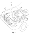
- a cooling system generally shown at 10 of a vehicle, generally shown in phantom at 12, circulates a fluid from an engine 14 through a hose 16 to a heat exchanger assembly or radiator, generally indicated at 18.
- the heat exchanger assembly 18 of the present invention includes a core 20 having first and second opposite ends 22 and 24 and opposite sides 26 and 28 for cooling the fluid flowing internally.
- the core 20 is disposed or extends between a pair of first and second header tanks 30 and 32.
- the first header tank 30 is disposed at the first end 22 of the core 20 and the second tank 32 is disposed at the second end 24 of the core 20.
- a plurality of tubes 34 through which the fluid normally flows horizontally, are disposed to extend between the first 30 and second 32 tanks, as is well known in the art.
- the ends of the tubes 34 are inserted into openings or slots 36 defined in the respective first 30 and second 32 tanks for the fluid flow therebetween.
- the first 30 and second 32 tanks also include fluid connectors 33, 35, respectively, to act as an inlet and an outlet to convey the fluid into and out of the first 30 and second 32 tanks.
- the core 20 includes a plurality of corrugated fins 40 shown in Figure 2. Each fin 40 is disposed between adjacent tubes 34 as is well known in the art. However, for simplicity, the fins 40 are not shown in the remaining Figures.
- the heat exchanger assembly 18 includes a plurality of tank caps, each generally indicated at 42.
- the tank caps 42 are configured for closing the opposite open ends of both of the first 30 and second 32 tanks at opposite terminal ends 22, 24 of the core 20.
- each tank cap 42 is disposed in engagement with the open end of the first 30 and second 32 tanks. More specifically, in order to facilitate the closure of the open ends of the first 30 and second 32 tanks, each tank cap 42 has a recess or a dished configuration with a bottom 44 and sidewalls 46 below a rim 48 for disposition in the open end of the first 30 and second 32 tanks.
- the sidewalls 46 engage the interior of the open end of each tank 30 or 32 and the rim 48 engage the open end of each tank 30, 32 for being brazed thereto.
- a pair of rectangular flanges 50 are integral with and extend outwardly in the opposite directions to the rim 48 of each tank cap 42.
- the rectangular flanges 50 are clinched or bent over and downward into the exterior of each of the first 30 and second 32 tanks.
- the core 20, the tanks 30, 32, the fins 40, the tubes 34, and the tank caps 42 consist of one homogenous material, namely a metal such as aluminum.
- a pair of a core reinforcing members extend along the opposite sides 26, 28 of the core 20.
- Each reinforcing member 52 presents terminal ends 54, 56 with each of the terminal ends 54, 56 presenting a pair of reversed interconnected first and second bends 58, 60 having an S-shaped configuration to engage the rim 48 of the adjacent tank cap 42.
- Each of the bends 58, 60 of the terminal ends 54, 56 are more narrow in width than the tank cap 42.
- a notch 62 is defined at each side of the terminal ends 54, 56 to define a bending joint between the second bend 60 at the intersection of the S-shaped configuration and the remainder of the reinforcing member 52.
- Each notch 62 assist to relieve stress applied to the core reinforcing member 52 thereby maintaining structural stability and braze clad surface contact as the heat exchanger assembly 18 is brazed.
- a gusset 64 is integral with and extends across the second bend 60 to provide structural support to each of the terminal ends 54, 56.
- Each of the core reinforcing members 52 includes a pair of spaced and parallel reinforcing flanges 70 extending upwardly and terminating short of the terminal ends 54, 56. The reinforcing flanges 70 extend upwardly along the sides of a flat bar.
- Each reinforcing member 52 consists of one homogenous material, namely a metal such as aluminum.
- the a mechanical connection for connecting each of the tank caps 42 to the adjacent terminal ends 54, 56 of the reinforcing members 52 has tabs 82 integral with and sloping outwardly and bent downwardly into an opening or cut-out portion 90 defined in each terminal end 54, 56 of the core reinforcing member 52.
- Each tab 82 has a head 84 and a neck 86 more narrow in width than the head 84.
- the neck 86 and the head 84 are interconnected by outwardly tapered sides 88 to define a dovetailed configuration of the tab 82.
- the cut-out portion 90 presents a rectangular configuration having a width complementary to the width of the neck 86 to receive the tab 82.
- the cut-out portion 90 is just wide enough to receive the neck 86 but is smaller than the head 84 to retain the tab 82 in the cut-out portion 90 for connecting or holding the core reinforcing members 52 to the tank caps 42 as the heat exchanger assembly 18 is brazed.
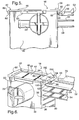
- the heat exchanger assembly 18 of the present invention may include an alternative embodiment that reverses the components by placing a pair of spaced tabs 190 to define a cut-out portion 192 in the tank cap 42 and a dove-tailed tab 182 extending from the terminal ends 54, 56. While only one tab 82, 182 and one complementary cut-out portion 90, 192 have been disclosed in the present invention, the number of tabs 82, 182 and complementary cut-out portions 90, 190 connecting the terminal ends 54, 56 of each reinforcing member 52 to the tank cap 42 may be more than one. In addition, the tab and /or cut-out portions may be at one or both ends of each tank cap 42.
- the aforementioned aluminum braze or brazing involves joining of components, such as, for example, the core 20 and the tanks 30, 32 prefabricated by having a brazing alloy (cladding) layer, i.e. outer layer (not shown) whose melting point is appreciably lower than that of the parent material (base alloy) base material, i.e. aluminum of the core 20 and the tanks 30, 32.
- the cladding, rolled onto the aluminum is oriented adjacent to or in between the components to be joined, like, for example, the tank cap 42 and the tanks 30 or 32, whereby the heat exchanger assembly 18 is heated to a temperature where the cladding material melts and the parent material, i.e. aluminum does not.
- the cladding Upon cooling, the cladding forms a metallurgical bond between the joining surfaces of the components, i.e. the core 20, the first 30 and second 32 header tanks, the core reinforcing members 52, and the caps 42.
- the brazing process occurs in a furnace (not shown) as is well known in the art.
- the cladding is supplied via a thin layer on the base alloy.
- the base alloy provides the structural integrity while the low melting point cladding melts to form the brazed joints.
- the core 20, the first 30 and second 32 tanks, the core reinforcing members 52, and the tank caps 42, are formed from aluminum, aluminum alloy, and the like, and are integrally brazed in the furnace to provide the heat exchanger assembly 18 having high corrosion resistance and high heat conductivity characteristics.
Landscapes
- Engineering & Computer Science (AREA)
- Physics & Mathematics (AREA)
- Thermal Sciences (AREA)
- Mechanical Engineering (AREA)
- General Engineering & Computer Science (AREA)
- Heat-Exchange Devices With Radiators And Conduit Assemblies (AREA)
- Motor Or Generator Cooling System (AREA)
Abstract
Description
- The subject invention relates to a heat exchanger assembly of the type having a tank at each end of a core with the tanks having open ends that are closed by caps.
- Typically, a heat exchanger includes a core having opposite ends and sides defined by a plurality of fins and tubes extending between the opposite sides and between the opposite ends. A pair of header tanks are disposed at the opposite ends of the core and are in fluid communication with the tubes. The header tanks have open ends closed by end caps. A pair of reinforcement members are held to the header tanks for brazing by passing the terminal ends of the reinforcement members through the header tanks.
- Various methods and designs have been used for holding reinforcement members to header tanks for brazing. Such methods and designs are disclosed in the United States Patent Nos.4,534,407 to Lardner; 5,236,042 to Kado; 5,289,873 to Ryan et al.; 6,179,050 to Dey et al.; 6,705,387 to Kokubunji et al.; the United States Patent Application No. 2003/0159816 to Kodumudi et al.; European Patent Specification No. EP0882940; and European Patent Application No. EP1030157.
- There is a constant need in the area of an automotive industry for improvements in a heat exchanger designs to improve the connection between the header tank and the reinforcement member for holding each of the reinforcement members to the header tanks as the heat exchanger assembly is brazed.
- A heat exchanger assembly for a motor vehicle includes a core having opposite sides and opposite ends with a plurality of fins extending between the opposite sides and a plurality of tubes extending between the opposite ends. First and second tanks have open ends and are disposed at the opposite ends of the core for fluid communication with the tubes. A plurality of tank caps close all of the open ends of the first and second tanks. A pair of core reinforcing members extend between terminal ends and are disposed along the opposite sides of the core. A tab and an opening for receiving the tab connect each of the tank caps to an adjacent terminal end of the reinforcing members. The tab has a head and a neck more narrower in width than the head with the opening smaller than the head for retaining the tab in the opening for connecting the reinforcing members to the tank caps as the heat exchanger is brazed.
- An advantage of the present invention is to provide a heat exchanger assembly having a connection for holding to and preventing detachment of each of the core reinforcing members to the first and second tanks as a separation forces are applied thereto.
- Other advantages of the present invention will be readily appreciated as the same becomes better understood by reference to the following detailed description when considered in connection with the accompanying drawings wherein:
- Figure 1 is a perspective view of a cooling system for an automotive vehicle with the automotive vehicle shown in phantom;
- Figure 2 is a front view of an heat exchanger assembly constructed in accordance with the subject invention;
- Figure 3 is a fragmentary perspective view showing the upper left corner without fins of the heat exchanger assembly showing a header tank and a tank cap having a plurality of tabs extending from the tank caps but without showing the fins between the tubes;
- Figure 4 is a fragmentary perspective view as shown in Figure 3 showing the tabs in the bend and final connecting position;
- Figure 5 is a fragmental side view of Figure 4;
- Figure 6 a fragmentary perspective view of an alternative embodiment of the present invention showing the tabs extending from the core reinforcement members; and
- Figure 7 is a fragmental side view of Figure 6.
- Referring to Figures 1, a cooling system, generally shown at 10 of a vehicle, generally shown in phantom at 12, circulates a fluid from an
engine 14 through ahose 16 to a heat exchanger assembly or radiator, generally indicated at 18. - As shown in Figure 2, the
heat exchanger assembly 18 of the present invention includes acore 20 having first and secondopposite ends opposite sides core 20 is disposed or extends between a pair of first andsecond header tanks first header tank 30 is disposed at thefirst end 22 of thecore 20 and thesecond tank 32 is disposed at thesecond end 24 of thecore 20. A plurality oftubes 34, through which the fluid normally flows horizontally, are disposed to extend between the first 30 and second 32 tanks, as is well known in the art. The ends of thetubes 34 are inserted into openings orslots 36 defined in the respective first 30 and second 32 tanks for the fluid flow therebetween. The first 30 and second 32 tanks also includefluid connectors core 20 includes a plurality ofcorrugated fins 40 shown in Figure 2. Eachfin 40 is disposed betweenadjacent tubes 34 as is well known in the art. However, for simplicity, thefins 40 are not shown in the remaining Figures. - The
heat exchanger assembly 18 includes a plurality of tank caps, each generally indicated at 42. Thetank caps 42 are configured for closing the opposite open ends of both of the first 30 and second 32 tanks atopposite terminal ends core 20. As illustrated in Figure 3, eachtank cap 42 is disposed in engagement with the open end of the first 30 and second 32 tanks. More specifically, in order to facilitate the closure of the open ends of the first 30 and second 32 tanks, eachtank cap 42 has a recess or a dished configuration with abottom 44 andsidewalls 46 below arim 48 for disposition in the open end of the first 30 and second 32 tanks. Thesidewalls 46 engage the interior of the open end of eachtank rim 48 engage the open end of eachtank rectangular flanges 50 are integral with and extend outwardly in the opposite directions to therim 48 of eachtank cap 42. Therectangular flanges 50 are clinched or bent over and downward into the exterior of each of the first 30 and second 32 tanks. Thecore 20, thetanks fins 40, thetubes 34, and thetank caps 42 consist of one homogenous material, namely a metal such as aluminum. - As is customary in the art, a pair of a core reinforcing members, each generally shown at 52, extend along the
opposite sides core 20. Each reinforcingmember 52 presentsterminal ends terminal ends second bends rim 48 of theadjacent tank cap 42. Each of thebends terminal ends tank cap 42. Anotch 62 is defined at each side of theterminal ends second bend 60 at the intersection of the S-shaped configuration and the remainder of the reinforcingmember 52. Eachnotch 62 assist to relieve stress applied to thecore reinforcing member 52 thereby maintaining structural stability and braze clad surface contact as theheat exchanger assembly 18 is brazed. Agusset 64 is integral with and extends across thesecond bend 60 to provide structural support to each of theterminal ends core reinforcing members 52 includes a pair of spaced and parallel reinforcingflanges 70 extending upwardly and terminating short of theterminal ends flanges 70 extend upwardly along the sides of a flat bar. Each reinforcingmember 52 consists of one homogenous material, namely a metal such as aluminum. - Referring to Figures 4 and 5, the a mechanical connection for connecting each of the
tank caps 42 to theadjacent terminal ends members 52 hastabs 82 integral with and sloping outwardly and bent downwardly into an opening or cut-outportion 90 defined in eachterminal end core reinforcing member 52. Eachtab 82 has ahead 84 and aneck 86 more narrow in width than thehead 84. Theneck 86 and thehead 84 are interconnected by outwardly taperedsides 88 to define a dovetailed configuration of thetab 82. The cut-outportion 90 presents a rectangular configuration having a width complementary to the width of theneck 86 to receive thetab 82. The cut-outportion 90 is just wide enough to receive theneck 86 but is smaller than thehead 84 to retain thetab 82 in the cut-outportion 90 for connecting or holding thecore reinforcing members 52 to thetank caps 42 as theheat exchanger assembly 18 is brazed. - As shown in Figures 6 and 7, the
heat exchanger assembly 18 of the present invention may include an alternative embodiment that reverses the components by placing a pair of spacedtabs 190 to define a cut-outportion 192 in thetank cap 42 and a dove-tailed tab 182 extending from theterminal ends tab portion tabs portions terminal ends member 52 to thetank cap 42 may be more than one. In addition, the tab and /or cut-out portions may be at one or both ends of eachtank cap 42. - As appreciated by those skilled in the art, the aforementioned aluminum braze or brazing involves joining of components, such as, for example, the
core 20 and thetanks core 20 and thetanks tank cap 42 and thetanks heat exchanger assembly 18 is heated to a temperature where the cladding material melts and the parent material, i.e. aluminum does not. Upon cooling, the cladding forms a metallurgical bond between the joining surfaces of the components, i.e. thecore 20, the first 30 and second 32 header tanks, thecore reinforcing members 52, and thecaps 42. The brazing process occurs in a furnace (not shown) as is well known in the art. - In automotive applications, the cladding is supplied via a thin layer on the base alloy. The base alloy provides the structural integrity while the low melting point cladding melts to form the brazed joints. The
core 20, the first 30 and second 32 tanks, thecore reinforcing members 52, and the tank caps 42, are formed from aluminum, aluminum alloy, and the like, and are integrally brazed in the furnace to provide theheat exchanger assembly 18 having high corrosion resistance and high heat conductivity characteristics. - While the invention has been described with reference to an exemplary embodiment, it will be understood by those skilled in the art that various changes may be made and equivalents may be substituted for elements thereof without departing from the scope of the invention. In addition, many modifications may be made to adapt a particular situation or material to the teachings of the invention without departing from the essential scope thereof. Therefore, it is intended that the invention not be limited to the particular embodiment disclosed as the best mode contemplated for carrying out this invention, but that the invention will include all embodiments falling within the scope of the appended claims.
Claims (14)
- A heat exchanger assembly (18) for a motor vehicle (12) comprising;
a core (20) having opposite ends (22, 24) and opposite sides (26, 28) with a plurality of fins (40) extending between said opposite sides (22, 24) and a plurality of tubes (34) extending between said opposite ends (22, 24),
first (30) and second (32) tanks having open ends and disposed at said opposite ends (22, 24) of said core (20) and in a fluid communication with said tubes (34),
a plurality of tank caps (42) with each tank cap (42) closing one of said open ends to close all of said open ends,
a pair of core reinforcing members (52) each extending between terminal ends (54, 56) and disposed along said opposite sides (26, 28) of said core (20),
at least one tab (82, 182) and an opening (90, 192) for receiving said tab (82, 182) for connecting each of said tank caps (42) to an adjacent terminal end (54, 56) of said reinforcing members (52), and
said tab (82, 182) having a head (84) and a neck (86) more narrow in width than said head (84) with said opening (90, 192) smaller than said head (84) for retaining said tab (82, 182) in said opening (90, 192) for connecting said core reinforcing members (52) to said tank caps (42) as said heat exchanger assembly (18) is brazed. - A heat exchanger assembly (18) as set forth in claim 1 wherein each tank cap (42) presents a recess having a bottom (44) and sidewalls (46) extending therefrom with said sidewalls (46) engaging the interior of each tank (30, 32) and a rim (48) surrounding said recess and engaging said open ends of each tank (30, 32).
- A heat exchanger assembly (18) as set forth in claim 2 including a pair of rectangular flanges (50) being integral with and extending outwardly in the opposite direction from said rim (48) of said tank cap (42) and extending downwardly to engage the exterior of each tank (30, 32).
- A heat exchanger assembly (18) as set forth in claim 3 wherein said at least one tab (82) is integral with and extends outwardly from said rim (48) of said tank cap (42) with said at least one tab (82) sloping to said core reinforcing member (52).
- A heat exchanger assembly (18) as set forth in claim 4 wherein said opening (90) is further defined by a cut-out portion presenting a rectangular configuration with said cut-out portion having a width with the width of said neck (86) complementary with the width of said cut-out portion.
- A heat exchanger assembly (18) as set forth in claim 5 wherein each of said terminal ends (54, 56) presents a S-shaped configuration having a pair of reversed bends (58, 60) having a S-shaped configuration with the first bend (58) overlying said rim (48).
- A heat exchanger assembly (18) as set forth in claim 6 wherein said reverse bends (58, 60) are more narrow in width than said tank cap (42).
- A heat exchanger assembly (18) as set forth in claim 7 wherein said neck (86) and said head (84) are interconnected by outwardly tapered sides (88) to define a dove-tailed configuration of each tab (82, 182).
- A heat exchanger assembly (18) as set forth in claim 7 wherein said second reverse bend (60) includes a pair of opposite notches (62) defined therein to present a bending joint between said second bend (60) at the intersection of said S-shape and the reminder of said core reinforcing member (52).
- A heat exchanger assembly (18) as set forth in claim 9 including a gusset (64) extending across said second bend (60) to provide structural support to each of said S-shaped configuration at said terminal ends (54, 56).
- A heat exchanger assembly (18) as set forth in claim 10 wherein each of said core reinforcing members (52) includes a pair of spaced and parallel reinforcing flanges (70)
- A heat exchanger assembly (18) as set forth in claim 11 wherein said reinforcing flanges (70) extend upwardly from said core reinforcing member (52) and terminate short of said terminal ends (54, 56).
- A heat exchanger assembly (18) as set forth in claim 12 wherein said core (20), said first (30) and second (32) tanks, said core reinforcing member (52), said tank caps (42), said tubes (34), and said fins (40) are formed from aluminum.
- A heat exchanger assembly (18) as set forth in claim 13 wherein said core (20), said first (30) and second (32) tanks, said core reinforcing member (52), said tank caps (42), said tubes (34), and said fins (40) are brazed together.
Applications Claiming Priority (1)
| Application Number | Priority Date | Filing Date | Title |
|---|---|---|---|
| US10/956,889 US7395853B2 (en) | 2004-10-01 | 2004-10-01 | Heat exchanger assembly for a motor vehicle |
Publications (2)
| Publication Number | Publication Date |
|---|---|
| EP1643201A1 true EP1643201A1 (en) | 2006-04-05 |
| EP1643201B1 EP1643201B1 (en) | 2007-07-25 |
Family
ID=35717622
Family Applications (1)
| Application Number | Title | Priority Date | Filing Date |
|---|---|---|---|
| EP05077196A Not-in-force EP1643201B1 (en) | 2004-10-01 | 2005-09-27 | A heat exchanger assembly for a motor vehicle |
Country Status (4)
| Country | Link |
|---|---|
| US (1) | US7395853B2 (en) |
| EP (1) | EP1643201B1 (en) |
| AT (1) | ATE368207T1 (en) |
| DE (1) | DE602005001744T2 (en) |
Cited By (1)
| Publication number | Priority date | Publication date | Assignee | Title |
|---|---|---|---|---|
| WO2018167446A1 (en) * | 2017-03-17 | 2018-09-20 | Valeo Systemes Thermiques | Radiator comprising an outward-facing u-shaped end plate, and corresponding heating ventilation or air-conditioning system |
Families Citing this family (12)
| Publication number | Priority date | Publication date | Assignee | Title |
|---|---|---|---|---|
| JP2007090962A (en) * | 2005-09-27 | 2007-04-12 | Denso Corp | Arrangement structure of parts around radiator |
| CN101226037A (en) * | 2008-01-30 | 2008-07-23 | 无锡优萌汽车部件制造有限公司 | Stitching structure for main tablet and side plate of novel vehicle warm air water chamber |
| USD619511S1 (en) * | 2009-12-23 | 2010-07-13 | Michael Sullivan | Radiator |
| US20120024508A1 (en) * | 2010-07-28 | 2012-02-02 | Delphi Technologies, Inc. | Reinforcement plate for multiple row heat exchanger |
| USD647436S1 (en) * | 2011-03-17 | 2011-10-25 | Michael Sullivan | Radiator |
| JP5746906B2 (en) * | 2011-04-28 | 2015-07-08 | 昭和電工株式会社 | Heat exchanger |
| USD717702S1 (en) * | 2014-04-29 | 2014-11-18 | Resource Intl, Inc. | Automotive radiator |
| DE112015002074T5 (en) | 2014-04-29 | 2017-02-23 | Dana Canada Corporation | Intercooler with multipart plastic housing |
| USD717218S1 (en) * | 2014-07-24 | 2014-11-11 | Resource Intl, Inc. | Automotive radiator |
| US10704842B2 (en) | 2018-08-21 | 2020-07-07 | Denso International America, Inc. | Side plate end tab for heat exchanger |
| FR3090837B1 (en) * | 2018-12-19 | 2021-01-15 | Valeo Systemes Thermiques | Heat exchanger with brazed end cheek |
| US11137210B2 (en) * | 2019-08-07 | 2021-10-05 | Denso International America, Inc. | Heat exchanger |
Citations (10)
| Publication number | Priority date | Publication date | Assignee | Title |
|---|---|---|---|---|
| FR2735855A1 (en) * | 1995-06-23 | 1996-12-27 | Valeo Climatisation | Fabrication procedure for heat exchanger tube and plate assembly |
| JPH09126685A (en) * | 1995-10-31 | 1997-05-16 | Denso Corp | Heat exchanger |
| EP1030157A1 (en) * | 1997-11-14 | 2000-08-23 | Zexel Corporation | Heat exchanger |
| JP2000283691A (en) * | 1999-03-30 | 2000-10-13 | Toyo Radiator Co Ltd | Heat exchanger |
| JP2003139484A (en) * | 2001-10-30 | 2003-05-14 | Denso Corp | Laminate heat exchanger |
| WO2005001370A1 (en) * | 2003-06-26 | 2005-01-06 | Toyo Radiator Co., Ltd. | Aluminum radiator |
| EP1500892A2 (en) * | 2003-07-22 | 2005-01-26 | Modine Manufacturing Company | Heat exchanger for vehicles |
| DE10343634A1 (en) * | 2003-09-20 | 2005-04-14 | Modine Manufacturing Co., Racine | Heat exchanger for a motor vehicle comprises sealing caps for sealing lateral openings in collecting tanks and having fixing elements for fixing the walls of the collecting tanks during insertion into the lateral openings |
| EP1528347A2 (en) * | 2003-10-29 | 2005-05-04 | Delphi Technologies, Inc. | End cap with an integral flow diverter |
| EP1553373A2 (en) * | 2004-01-08 | 2005-07-13 | Delphi Technologies, Inc. | One piece integral reinforcement with angled end caps to facilitate assembly to core |
Family Cites Families (23)
| Publication number | Priority date | Publication date | Assignee | Title |
|---|---|---|---|---|
| US4406132A (en) * | 1980-05-19 | 1983-09-27 | Carrier Corporation | Method for assembling an air conditioning unit including a tube sheet isolator |
| FR2507760B1 (en) * | 1981-06-12 | 1986-05-02 | Valeo | DEVICE FOR FIXING A HEAT EXCHANGER IN A HOUSING AND MOTOR VEHICLE HEATING OR AIR CONDITIONING INSTALLATION |
| EP0102715A3 (en) | 1982-09-03 | 1984-08-01 | Unipart Group Limited | Improvements relating to heat exchangers |
| JPH01114697A (en) * | 1987-10-29 | 1989-05-08 | Nippon Denso Co Ltd | Heat exchanger |
| JPH0240495A (en) * | 1988-08-01 | 1990-02-09 | Nippon Denso Co Ltd | Heat exchanger |
| JP2968063B2 (en) | 1991-02-20 | 1999-10-25 | サンデン株式会社 | Heat exchanger |
| JPH0560485A (en) * | 1992-02-24 | 1993-03-09 | Nippondenso Co Ltd | Refrigerant condenser |
| US5289873A (en) | 1992-06-22 | 1994-03-01 | General Motors Corporation | Heat exchanger sideplate interlocked with header |
| US5542176A (en) * | 1992-09-21 | 1996-08-06 | Hideaki Serizawa | Radiation plate and method of producing the same |
| JP3393957B2 (en) * | 1995-05-30 | 2003-04-07 | サンデン株式会社 | Heat exchanger fluid supply / drain pipe joining method |
| JP3677898B2 (en) * | 1996-10-22 | 2005-08-03 | 株式会社デンソー | Double heat exchanger |
| JPH10332293A (en) | 1997-06-02 | 1998-12-15 | Mitsubishi Heavy Ind Ltd | Heat exchanger |
| WO2000022366A1 (en) * | 1998-10-09 | 2000-04-20 | S.C. Romradiatoare S.A. | High efficiency heat exchanger with oval tubes |
| JP4281175B2 (en) * | 1999-09-29 | 2009-06-17 | 株式会社デンソー | Double heat exchanger |
| US6179050B1 (en) | 1999-09-29 | 2001-01-30 | Valeo Thermique Moteur | Heat exchangers |
| JP2002081884A (en) * | 2000-09-07 | 2002-03-22 | Denso Corp | Mounting structure of heat exchanger |
| US6929059B2 (en) * | 2001-04-09 | 2005-08-16 | Halla Climate Control Corporation | Aluminum radiator and method of manufacturing tank thereof |
| JP2002350086A (en) * | 2001-05-23 | 2002-12-04 | Denso Corp | Heat exchanger |
| US6529377B1 (en) * | 2001-09-05 | 2003-03-04 | Microelectronic & Computer Technology Corporation | Integrated cooling system |
| US20030159816A1 (en) | 2002-02-22 | 2003-08-28 | Valeo Inc. | Heat exchanger apparatus with integrated supply/return tube |
| US6829814B1 (en) * | 2002-08-29 | 2004-12-14 | Delphi Technologies, Inc. | Process of making an all-silicon microphone |
| US20050230089A1 (en) * | 2004-04-05 | 2005-10-20 | Denso Corporation | Heat exchanger capable of preventing heat stress |
| CN2701074Y (en) * | 2004-04-29 | 2005-05-18 | 鸿富锦精密工业(深圳)有限公司 | Liquid cooling type heat sink |
-
2004
- 2004-10-01 US US10/956,889 patent/US7395853B2/en not_active Expired - Fee Related
-
2005
- 2005-09-27 AT AT05077196T patent/ATE368207T1/en not_active IP Right Cessation
- 2005-09-27 EP EP05077196A patent/EP1643201B1/en not_active Not-in-force
- 2005-09-27 DE DE602005001744T patent/DE602005001744T2/en active Active
Patent Citations (10)
| Publication number | Priority date | Publication date | Assignee | Title |
|---|---|---|---|---|
| FR2735855A1 (en) * | 1995-06-23 | 1996-12-27 | Valeo Climatisation | Fabrication procedure for heat exchanger tube and plate assembly |
| JPH09126685A (en) * | 1995-10-31 | 1997-05-16 | Denso Corp | Heat exchanger |
| EP1030157A1 (en) * | 1997-11-14 | 2000-08-23 | Zexel Corporation | Heat exchanger |
| JP2000283691A (en) * | 1999-03-30 | 2000-10-13 | Toyo Radiator Co Ltd | Heat exchanger |
| JP2003139484A (en) * | 2001-10-30 | 2003-05-14 | Denso Corp | Laminate heat exchanger |
| WO2005001370A1 (en) * | 2003-06-26 | 2005-01-06 | Toyo Radiator Co., Ltd. | Aluminum radiator |
| EP1500892A2 (en) * | 2003-07-22 | 2005-01-26 | Modine Manufacturing Company | Heat exchanger for vehicles |
| DE10343634A1 (en) * | 2003-09-20 | 2005-04-14 | Modine Manufacturing Co., Racine | Heat exchanger for a motor vehicle comprises sealing caps for sealing lateral openings in collecting tanks and having fixing elements for fixing the walls of the collecting tanks during insertion into the lateral openings |
| EP1528347A2 (en) * | 2003-10-29 | 2005-05-04 | Delphi Technologies, Inc. | End cap with an integral flow diverter |
| EP1553373A2 (en) * | 2004-01-08 | 2005-07-13 | Delphi Technologies, Inc. | One piece integral reinforcement with angled end caps to facilitate assembly to core |
Non-Patent Citations (3)
| Title |
|---|
| PATENT ABSTRACTS OF JAPAN vol. 1997, no. 09 30 September 1997 (1997-09-30) * |
| PATENT ABSTRACTS OF JAPAN vol. 2000, no. 13 5 February 2001 (2001-02-05) * |
| PATENT ABSTRACTS OF JAPAN vol. 2003, no. 09 3 September 2003 (2003-09-03) * |
Cited By (4)
| Publication number | Priority date | Publication date | Assignee | Title |
|---|---|---|---|---|
| WO2018167446A1 (en) * | 2017-03-17 | 2018-09-20 | Valeo Systemes Thermiques | Radiator comprising an outward-facing u-shaped end plate, and corresponding heating ventilation or air-conditioning system |
| FR3064054A1 (en) * | 2017-03-17 | 2018-09-21 | Valeo Systemes Thermiques | EXTERMITE U-PLATE RADIATOR ORIENTED TO OUTSIDE, AND HEATING SYSTEM, VENTILATION OR AIR CONDITIONING THEREFOR |
| CN110431372A (en) * | 2017-03-17 | 2019-11-08 | 法雷奥热系统公司 | Radiators including outward U-shaped end plates and corresponding heating, ventilation or air conditioning systems |
| CN110431372B (en) * | 2017-03-17 | 2022-09-27 | 法雷奥热系统公司 | Radiator comprising an outwardly U-shaped end plate and corresponding heating, ventilation or air-conditioning system |
Also Published As
| Publication number | Publication date |
|---|---|
| DE602005001744D1 (en) | 2007-09-06 |
| US20060070725A1 (en) | 2006-04-06 |
| DE602005001744T2 (en) | 2008-04-30 |
| US7395853B2 (en) | 2008-07-08 |
| ATE368207T1 (en) | 2007-08-15 |
| EP1643201B1 (en) | 2007-07-25 |
Similar Documents
| Publication | Publication Date | Title |
|---|---|---|
| US7461685B2 (en) | Heat exchanger | |
| US7395853B2 (en) | Heat exchanger assembly for a motor vehicle | |
| EP0641986B1 (en) | Heat exchanger and method for manufacturing thereof | |
| US7461689B2 (en) | Thermal cycling resistant tube to header joint for heat exchangers | |
| AU679783B2 (en) | Aluminum heat exchanger | |
| EP1030157B1 (en) | Heat exchanger | |
| AU644234B2 (en) | Heat exchanger | |
| US5678628A (en) | Heat exchanger and method for manufacturing the same | |
| JP2001194080A (en) | Heat exchanger | |
| JP4105320B2 (en) | Heat exchanger | |
| WO2003060415A1 (en) | Mounting bracket for heat exchanger cores | |
| JPH10206071A (en) | Heat exchanger tank | |
| AU709669B2 (en) | Heat exchanger | |
| EP0798530A1 (en) | Heat exchanger | |
| JPH11347666A (en) | Heat exchanger, and its manufacture | |
| JP4866571B2 (en) | Heat exchanger | |
| JP2750167B2 (en) | Heat exchanger | |
| JP2003106791A (en) | Heat exchanger | |
| JPH0886590A (en) | Tank for integrated heat exchanger | |
| EP1004841B1 (en) | Heat exchanger tank | |
| JP3207317B2 (en) | Aluminum alloy heat exchanger | |
| JP3517230B2 (en) | Heat exchanger pipe assembly structure | |
| CN112739972A (en) | Compliant B-tube for heat sink applications | |
| JP4412770B2 (en) | Heat exchanger | |
| JP3209856B2 (en) | Manufacturing method of heat exchanger made of aluminum material |
Legal Events
| Date | Code | Title | Description |
|---|---|---|---|
| PUAI | Public reference made under article 153(3) epc to a published international application that has entered the european phase |
Free format text: ORIGINAL CODE: 0009012 |
|
| AK | Designated contracting states |
Kind code of ref document: A1 Designated state(s): AT BE BG CH CY CZ DE DK EE ES FI FR GB GR HU IE IS IT LI LT LU LV MC NL PL PT RO SE SI SK TR |
|
| AX | Request for extension of the european patent |
Extension state: AL BA HR MK YU |
|
| 17P | Request for examination filed |
Effective date: 20061005 |
|
| 17Q | First examination report despatched |
Effective date: 20061107 |
|
| AKX | Designation fees paid |
Designated state(s): AT BE BG CH CY CZ DE DK EE ES FI FR GB GR HU IE IS IT LI LT LU LV MC NL PL PT RO SE SI SK TR |
|
| GRAP | Despatch of communication of intention to grant a patent |
Free format text: ORIGINAL CODE: EPIDOSNIGR1 |
|
| GRAS | Grant fee paid |
Free format text: ORIGINAL CODE: EPIDOSNIGR3 |
|
| GRAA | (expected) grant |
Free format text: ORIGINAL CODE: 0009210 |
|
| AK | Designated contracting states |
Kind code of ref document: B1 Designated state(s): AT BE BG CH CY CZ DE DK EE ES FI FR GB GR HU IE IS IT LI LT LU LV MC NL PL PT RO SE SI SK TR |
|
| REG | Reference to a national code |
Ref country code: GB Ref legal event code: FG4D |
|
| REG | Reference to a national code |
Ref country code: CH Ref legal event code: EP |
|
| REG | Reference to a national code |
Ref country code: IE Ref legal event code: FG4D |
|
| REF | Corresponds to: |
Ref document number: 602005001744 Country of ref document: DE Date of ref document: 20070906 Kind code of ref document: P |
|
| ET | Fr: translation filed | ||
| PG25 | Lapsed in a contracting state [announced via postgrant information from national office to epo] |
Ref country code: ES Free format text: LAPSE BECAUSE OF FAILURE TO SUBMIT A TRANSLATION OF THE DESCRIPTION OR TO PAY THE FEE WITHIN THE PRESCRIBED TIME-LIMIT Effective date: 20071105 Ref country code: PT Free format text: LAPSE BECAUSE OF FAILURE TO SUBMIT A TRANSLATION OF THE DESCRIPTION OR TO PAY THE FEE WITHIN THE PRESCRIBED TIME-LIMIT Effective date: 20071226 Ref country code: IS Free format text: LAPSE BECAUSE OF FAILURE TO SUBMIT A TRANSLATION OF THE DESCRIPTION OR TO PAY THE FEE WITHIN THE PRESCRIBED TIME-LIMIT Effective date: 20071125 Ref country code: FI Free format text: LAPSE BECAUSE OF FAILURE TO SUBMIT A TRANSLATION OF THE DESCRIPTION OR TO PAY THE FEE WITHIN THE PRESCRIBED TIME-LIMIT Effective date: 20070725 Ref country code: LT Free format text: LAPSE BECAUSE OF FAILURE TO SUBMIT A TRANSLATION OF THE DESCRIPTION OR TO PAY THE FEE WITHIN THE PRESCRIBED TIME-LIMIT Effective date: 20070725 Ref country code: NL Free format text: LAPSE BECAUSE OF FAILURE TO SUBMIT A TRANSLATION OF THE DESCRIPTION OR TO PAY THE FEE WITHIN THE PRESCRIBED TIME-LIMIT Effective date: 20070725 Ref country code: BG Free format text: LAPSE BECAUSE OF FAILURE TO SUBMIT A TRANSLATION OF THE DESCRIPTION OR TO PAY THE FEE WITHIN THE PRESCRIBED TIME-LIMIT Effective date: 20071025 |
|
| REG | Reference to a national code |
Ref country code: CH Ref legal event code: PL |
|
| NLV1 | Nl: lapsed or annulled due to failure to fulfill the requirements of art. 29p and 29m of the patents act | ||
| PG25 | Lapsed in a contracting state [announced via postgrant information from national office to epo] |
Ref country code: PL Free format text: LAPSE BECAUSE OF FAILURE TO SUBMIT A TRANSLATION OF THE DESCRIPTION OR TO PAY THE FEE WITHIN THE PRESCRIBED TIME-LIMIT Effective date: 20070725 Ref country code: LI Free format text: LAPSE BECAUSE OF FAILURE TO SUBMIT A TRANSLATION OF THE DESCRIPTION OR TO PAY THE FEE WITHIN THE PRESCRIBED TIME-LIMIT Effective date: 20070725 Ref country code: AT Free format text: LAPSE BECAUSE OF FAILURE TO SUBMIT A TRANSLATION OF THE DESCRIPTION OR TO PAY THE FEE WITHIN THE PRESCRIBED TIME-LIMIT Effective date: 20070725 Ref country code: CH Free format text: LAPSE BECAUSE OF FAILURE TO SUBMIT A TRANSLATION OF THE DESCRIPTION OR TO PAY THE FEE WITHIN THE PRESCRIBED TIME-LIMIT Effective date: 20070725 |
|
| PG25 | Lapsed in a contracting state [announced via postgrant information from national office to epo] |
Ref country code: BE Free format text: LAPSE BECAUSE OF FAILURE TO SUBMIT A TRANSLATION OF THE DESCRIPTION OR TO PAY THE FEE WITHIN THE PRESCRIBED TIME-LIMIT Effective date: 20070725 Ref country code: LV Free format text: LAPSE BECAUSE OF FAILURE TO SUBMIT A TRANSLATION OF THE DESCRIPTION OR TO PAY THE FEE WITHIN THE PRESCRIBED TIME-LIMIT Effective date: 20070725 |
|
| PG25 | Lapsed in a contracting state [announced via postgrant information from national office to epo] |
Ref country code: DK Free format text: LAPSE BECAUSE OF FAILURE TO SUBMIT A TRANSLATION OF THE DESCRIPTION OR TO PAY THE FEE WITHIN THE PRESCRIBED TIME-LIMIT Effective date: 20070725 Ref country code: MC Free format text: LAPSE BECAUSE OF NON-PAYMENT OF DUE FEES Effective date: 20070930 Ref country code: GR Free format text: LAPSE BECAUSE OF FAILURE TO SUBMIT A TRANSLATION OF THE DESCRIPTION OR TO PAY THE FEE WITHIN THE PRESCRIBED TIME-LIMIT Effective date: 20071026 |
|
| PG25 | Lapsed in a contracting state [announced via postgrant information from national office to epo] |
Ref country code: CZ Free format text: LAPSE BECAUSE OF FAILURE TO SUBMIT A TRANSLATION OF THE DESCRIPTION OR TO PAY THE FEE WITHIN THE PRESCRIBED TIME-LIMIT Effective date: 20070725 Ref country code: SK Free format text: LAPSE BECAUSE OF FAILURE TO SUBMIT A TRANSLATION OF THE DESCRIPTION OR TO PAY THE FEE WITHIN THE PRESCRIBED TIME-LIMIT Effective date: 20070725 |
|
| PLBE | No opposition filed within time limit |
Free format text: ORIGINAL CODE: 0009261 |
|
| STAA | Information on the status of an ep patent application or granted ep patent |
Free format text: STATUS: NO OPPOSITION FILED WITHIN TIME LIMIT |
|
| PG25 | Lapsed in a contracting state [announced via postgrant information from national office to epo] |
Ref country code: RO Free format text: LAPSE BECAUSE OF FAILURE TO SUBMIT A TRANSLATION OF THE DESCRIPTION OR TO PAY THE FEE WITHIN THE PRESCRIBED TIME-LIMIT Effective date: 20070725 Ref country code: SE Free format text: LAPSE BECAUSE OF FAILURE TO SUBMIT A TRANSLATION OF THE DESCRIPTION OR TO PAY THE FEE WITHIN THE PRESCRIBED TIME-LIMIT Effective date: 20071025 |
|
| 26N | No opposition filed |
Effective date: 20080428 |
|
| PG25 | Lapsed in a contracting state [announced via postgrant information from national office to epo] |
Ref country code: IE Free format text: LAPSE BECAUSE OF NON-PAYMENT OF DUE FEES Effective date: 20070927 |
|
| PG25 | Lapsed in a contracting state [announced via postgrant information from national office to epo] |
Ref country code: EE Free format text: LAPSE BECAUSE OF FAILURE TO SUBMIT A TRANSLATION OF THE DESCRIPTION OR TO PAY THE FEE WITHIN THE PRESCRIBED TIME-LIMIT Effective date: 20070725 |
|
| PG25 | Lapsed in a contracting state [announced via postgrant information from national office to epo] |
Ref country code: SI Free format text: LAPSE BECAUSE OF FAILURE TO SUBMIT A TRANSLATION OF THE DESCRIPTION OR TO PAY THE FEE WITHIN THE PRESCRIBED TIME-LIMIT Effective date: 20070725 |
|
| PG25 | Lapsed in a contracting state [announced via postgrant information from national office to epo] |
Ref country code: CY Free format text: LAPSE BECAUSE OF FAILURE TO SUBMIT A TRANSLATION OF THE DESCRIPTION OR TO PAY THE FEE WITHIN THE PRESCRIBED TIME-LIMIT Effective date: 20070725 |
|
| PG25 | Lapsed in a contracting state [announced via postgrant information from national office to epo] |
Ref country code: LU Free format text: LAPSE BECAUSE OF NON-PAYMENT OF DUE FEES Effective date: 20070927 |
|
| PG25 | Lapsed in a contracting state [announced via postgrant information from national office to epo] |
Ref country code: TR Free format text: LAPSE BECAUSE OF FAILURE TO SUBMIT A TRANSLATION OF THE DESCRIPTION OR TO PAY THE FEE WITHIN THE PRESCRIBED TIME-LIMIT Effective date: 20070725 Ref country code: HU Free format text: LAPSE BECAUSE OF FAILURE TO SUBMIT A TRANSLATION OF THE DESCRIPTION OR TO PAY THE FEE WITHIN THE PRESCRIBED TIME-LIMIT Effective date: 20080126 |
|
| GBPC | Gb: european patent ceased through non-payment of renewal fee |
Effective date: 20090927 |
|
| PG25 | Lapsed in a contracting state [announced via postgrant information from national office to epo] |
Ref country code: GB Free format text: LAPSE BECAUSE OF NON-PAYMENT OF DUE FEES Effective date: 20070725 |
|
| PG25 | Lapsed in a contracting state [announced via postgrant information from national office to epo] |
Ref country code: IT Free format text: LAPSE BECAUSE OF NON-PAYMENT OF DUE FEES Effective date: 20070930 |
|
| REG | Reference to a national code |
Ref country code: FR Ref legal event code: PLFP Year of fee payment: 11 |
|
| REG | Reference to a national code |
Ref country code: DE Ref legal event code: R082 Ref document number: 602005001744 Country of ref document: DE Representative=s name: BRP RENAUD UND PARTNER MBB, DE Ref country code: DE Ref legal event code: R081 Ref document number: 602005001744 Country of ref document: DE Owner name: MAHLE INTERNATIONAL GMBH, DE Free format text: FORMER OWNER: DELPHI TECHNOLOGIES, INC., TROY, MICH., US Ref country code: DE Ref legal event code: R082 Ref document number: 602005001744 Country of ref document: DE Representative=s name: BRP RENAUD UND PARTNER MBB RECHTSANWAELTE PATE, DE |
|
| REG | Reference to a national code |
Ref country code: FR Ref legal event code: PLFP Year of fee payment: 12 |
|
| REG | Reference to a national code |
Ref country code: FR Ref legal event code: PLFP Year of fee payment: 13 |
|
| REG | Reference to a national code |
Ref country code: FR Ref legal event code: TP Owner name: MAHLE INTERNATIONAL GMBH, DE Effective date: 20180103 |
|
| REG | Reference to a national code |
Ref country code: FR Ref legal event code: PLFP Year of fee payment: 14 |
|
| PGFP | Annual fee paid to national office [announced via postgrant information from national office to epo] |
Ref country code: FR Payment date: 20180928 Year of fee payment: 14 |
|
| PGFP | Annual fee paid to national office [announced via postgrant information from national office to epo] |
Ref country code: DE Payment date: 20181130 Year of fee payment: 14 |
|
| REG | Reference to a national code |
Ref country code: DE Ref legal event code: R119 Ref document number: 602005001744 Country of ref document: DE |
|
| PG25 | Lapsed in a contracting state [announced via postgrant information from national office to epo] |
Ref country code: DE Free format text: LAPSE BECAUSE OF NON-PAYMENT OF DUE FEES Effective date: 20200401 |
|
| PG25 | Lapsed in a contracting state [announced via postgrant information from national office to epo] |
Ref country code: FR Free format text: LAPSE BECAUSE OF NON-PAYMENT OF DUE FEES Effective date: 20190930 |