EP1642700B1 - Method and apparatus for moving a sealing jaw - Google Patents
Method and apparatus for moving a sealing jaw Download PDFInfo
- Publication number
- EP1642700B1 EP1642700B1 EP05020645A EP05020645A EP1642700B1 EP 1642700 B1 EP1642700 B1 EP 1642700B1 EP 05020645 A EP05020645 A EP 05020645A EP 05020645 A EP05020645 A EP 05020645A EP 1642700 B1 EP1642700 B1 EP 1642700B1
- Authority
- EP
- European Patent Office
- Prior art keywords
- welding jaw
- drives
- jaw
- welding
- article
- Prior art date
- Legal status (The legal status is an assumption and is not a legal conclusion. Google has not performed a legal analysis and makes no representation as to the accuracy of the status listed.)
- Active
Links
- 238000007789 sealing Methods 0.000 title claims abstract description 27
- 238000000034 method Methods 0.000 title claims abstract description 19
- 238000003466 welding Methods 0.000 claims abstract description 74
- 230000033001 locomotion Effects 0.000 claims abstract description 30
- 230000001133 acceleration Effects 0.000 claims abstract description 17
- 230000001419 dependent effect Effects 0.000 claims abstract description 7
- 238000001816 cooling Methods 0.000 claims description 18
- 238000010438 heat treatment Methods 0.000 claims 3
- 230000000694 effects Effects 0.000 claims 2
- 239000000725 suspension Substances 0.000 abstract description 2
- 238000010586 diagram Methods 0.000 description 3
- 239000011888 foil Substances 0.000 description 3
- 238000006243 chemical reaction Methods 0.000 description 2
- 206010034016 Paronychia Diseases 0.000 description 1
- 230000006978 adaptation Effects 0.000 description 1
- 230000005540 biological transmission Effects 0.000 description 1
- 238000010276 construction Methods 0.000 description 1
- 238000006073 displacement reaction Methods 0.000 description 1
- 238000004806 packaging method and process Methods 0.000 description 1
Images

Classifications
-
- B—PERFORMING OPERATIONS; TRANSPORTING
- B29—WORKING OF PLASTICS; WORKING OF SUBSTANCES IN A PLASTIC STATE IN GENERAL
- B29C—SHAPING OR JOINING OF PLASTICS; SHAPING OF MATERIAL IN A PLASTIC STATE, NOT OTHERWISE PROVIDED FOR; AFTER-TREATMENT OF THE SHAPED PRODUCTS, e.g. REPAIRING
- B29C66/00—General aspects of processes or apparatus for joining preformed parts
- B29C66/80—General aspects of machine operations or constructions and parts thereof
- B29C66/81—General aspects of the pressing elements, i.e. the elements applying pressure on the parts to be joined in the area to be joined, e.g. the welding jaws or clamps
- B29C66/818—General aspects of the pressing elements, i.e. the elements applying pressure on the parts to be joined in the area to be joined, e.g. the welding jaws or clamps characterised by the cooling constructional aspects, or by the thermal or electrical insulating or conducting constructional aspects of the welding jaws or of the clamps ; comprising means for compensating for the thermal expansion of the welding jaws or of the clamps
- B29C66/8181—General aspects of the pressing elements, i.e. the elements applying pressure on the parts to be joined in the area to be joined, e.g. the welding jaws or clamps characterised by the cooling constructional aspects, or by the thermal or electrical insulating or conducting constructional aspects of the welding jaws or of the clamps ; comprising means for compensating for the thermal expansion of the welding jaws or of the clamps characterised by the cooling constructional aspects
- B29C66/81811—General aspects of the pressing elements, i.e. the elements applying pressure on the parts to be joined in the area to be joined, e.g. the welding jaws or clamps characterised by the cooling constructional aspects, or by the thermal or electrical insulating or conducting constructional aspects of the welding jaws or of the clamps ; comprising means for compensating for the thermal expansion of the welding jaws or of the clamps characterised by the cooling constructional aspects of the welding jaws
- B29C66/81812—General aspects of the pressing elements, i.e. the elements applying pressure on the parts to be joined in the area to be joined, e.g. the welding jaws or clamps characterised by the cooling constructional aspects, or by the thermal or electrical insulating or conducting constructional aspects of the welding jaws or of the clamps ; comprising means for compensating for the thermal expansion of the welding jaws or of the clamps characterised by the cooling constructional aspects of the welding jaws the welding jaws being cooled from the outside, e.g. by blowing a gas or spraying a liquid
-
- B—PERFORMING OPERATIONS; TRANSPORTING
- B29—WORKING OF PLASTICS; WORKING OF SUBSTANCES IN A PLASTIC STATE IN GENERAL
- B29C—SHAPING OR JOINING OF PLASTICS; SHAPING OF MATERIAL IN A PLASTIC STATE, NOT OTHERWISE PROVIDED FOR; AFTER-TREATMENT OF THE SHAPED PRODUCTS, e.g. REPAIRING
- B29C65/00—Joining or sealing of preformed parts, e.g. welding of plastics materials; Apparatus therefor
- B29C65/02—Joining or sealing of preformed parts, e.g. welding of plastics materials; Apparatus therefor by heating, with or without pressure
- B29C65/18—Joining or sealing of preformed parts, e.g. welding of plastics materials; Apparatus therefor by heating, with or without pressure using heated tools
-
- B—PERFORMING OPERATIONS; TRANSPORTING
- B29—WORKING OF PLASTICS; WORKING OF SUBSTANCES IN A PLASTIC STATE IN GENERAL
- B29C—SHAPING OR JOINING OF PLASTICS; SHAPING OF MATERIAL IN A PLASTIC STATE, NOT OTHERWISE PROVIDED FOR; AFTER-TREATMENT OF THE SHAPED PRODUCTS, e.g. REPAIRING
- B29C65/00—Joining or sealing of preformed parts, e.g. welding of plastics materials; Apparatus therefor
- B29C65/74—Joining or sealing of preformed parts, e.g. welding of plastics materials; Apparatus therefor by welding and severing, or by joining and severing, the severing being performed in the area to be joined, next to the area to be joined, in the joint area or next to the joint area
- B29C65/745—Joining or sealing of preformed parts, e.g. welding of plastics materials; Apparatus therefor by welding and severing, or by joining and severing, the severing being performed in the area to be joined, next to the area to be joined, in the joint area or next to the joint area using a single unit having both a severing tool and a welding tool
-
- B—PERFORMING OPERATIONS; TRANSPORTING
- B29—WORKING OF PLASTICS; WORKING OF SUBSTANCES IN A PLASTIC STATE IN GENERAL
- B29C—SHAPING OR JOINING OF PLASTICS; SHAPING OF MATERIAL IN A PLASTIC STATE, NOT OTHERWISE PROVIDED FOR; AFTER-TREATMENT OF THE SHAPED PRODUCTS, e.g. REPAIRING
- B29C66/00—General aspects of processes or apparatus for joining preformed parts
- B29C66/01—General aspects dealing with the joint area or with the area to be joined
- B29C66/02—Preparation of the material, in the area to be joined, prior to joining or welding
- B29C66/024—Thermal pre-treatments
- B29C66/0242—Heating, or preheating, e.g. drying
-
- B—PERFORMING OPERATIONS; TRANSPORTING
- B29—WORKING OF PLASTICS; WORKING OF SUBSTANCES IN A PLASTIC STATE IN GENERAL
- B29C—SHAPING OR JOINING OF PLASTICS; SHAPING OF MATERIAL IN A PLASTIC STATE, NOT OTHERWISE PROVIDED FOR; AFTER-TREATMENT OF THE SHAPED PRODUCTS, e.g. REPAIRING
- B29C66/00—General aspects of processes or apparatus for joining preformed parts
- B29C66/01—General aspects dealing with the joint area or with the area to be joined
- B29C66/03—After-treatments in the joint area
- B29C66/034—Thermal after-treatments
- B29C66/0342—Cooling, e.g. transporting through welding and cooling zone
-
- B—PERFORMING OPERATIONS; TRANSPORTING
- B29—WORKING OF PLASTICS; WORKING OF SUBSTANCES IN A PLASTIC STATE IN GENERAL
- B29C—SHAPING OR JOINING OF PLASTICS; SHAPING OF MATERIAL IN A PLASTIC STATE, NOT OTHERWISE PROVIDED FOR; AFTER-TREATMENT OF THE SHAPED PRODUCTS, e.g. REPAIRING
- B29C66/00—General aspects of processes or apparatus for joining preformed parts
- B29C66/01—General aspects dealing with the joint area or with the area to be joined
- B29C66/05—Particular design of joint configurations
- B29C66/10—Particular design of joint configurations particular design of the joint cross-sections
- B29C66/11—Joint cross-sections comprising a single joint-segment, i.e. one of the parts to be joined comprising a single joint-segment in the joint cross-section
- B29C66/112—Single lapped joints
- B29C66/1122—Single lap to lap joints, i.e. overlap joints
-
- B—PERFORMING OPERATIONS; TRANSPORTING
- B29—WORKING OF PLASTICS; WORKING OF SUBSTANCES IN A PLASTIC STATE IN GENERAL
- B29C—SHAPING OR JOINING OF PLASTICS; SHAPING OF MATERIAL IN A PLASTIC STATE, NOT OTHERWISE PROVIDED FOR; AFTER-TREATMENT OF THE SHAPED PRODUCTS, e.g. REPAIRING
- B29C66/00—General aspects of processes or apparatus for joining preformed parts
- B29C66/40—General aspects of joining substantially flat articles, e.g. plates, sheets or web-like materials; Making flat seams in tubular or hollow articles; Joining single elements to substantially flat surfaces
- B29C66/41—Joining substantially flat articles ; Making flat seams in tubular or hollow articles
- B29C66/43—Joining a relatively small portion of the surface of said articles
- B29C66/431—Joining the articles to themselves
- B29C66/4312—Joining the articles to themselves for making flat seams in tubular or hollow articles, e.g. transversal seams
-
- B—PERFORMING OPERATIONS; TRANSPORTING
- B29—WORKING OF PLASTICS; WORKING OF SUBSTANCES IN A PLASTIC STATE IN GENERAL
- B29C—SHAPING OR JOINING OF PLASTICS; SHAPING OF MATERIAL IN A PLASTIC STATE, NOT OTHERWISE PROVIDED FOR; AFTER-TREATMENT OF THE SHAPED PRODUCTS, e.g. REPAIRING
- B29C66/00—General aspects of processes or apparatus for joining preformed parts
- B29C66/80—General aspects of machine operations or constructions and parts thereof
- B29C66/81—General aspects of the pressing elements, i.e. the elements applying pressure on the parts to be joined in the area to be joined, e.g. the welding jaws or clamps
- B29C66/814—General aspects of the pressing elements, i.e. the elements applying pressure on the parts to be joined in the area to be joined, e.g. the welding jaws or clamps characterised by the design of the pressing elements, e.g. of the welding jaws or clamps
- B29C66/8141—General aspects of the pressing elements, i.e. the elements applying pressure on the parts to be joined in the area to be joined, e.g. the welding jaws or clamps characterised by the design of the pressing elements, e.g. of the welding jaws or clamps characterised by the surface geometry of the part of the pressing elements, e.g. welding jaws or clamps, coming into contact with the parts to be joined
- B29C66/81427—General aspects of the pressing elements, i.e. the elements applying pressure on the parts to be joined in the area to be joined, e.g. the welding jaws or clamps characterised by the design of the pressing elements, e.g. of the welding jaws or clamps characterised by the surface geometry of the part of the pressing elements, e.g. welding jaws or clamps, coming into contact with the parts to be joined comprising a single ridge, e.g. for making a weakening line; comprising a single tooth
-
- B—PERFORMING OPERATIONS; TRANSPORTING
- B29—WORKING OF PLASTICS; WORKING OF SUBSTANCES IN A PLASTIC STATE IN GENERAL
- B29C—SHAPING OR JOINING OF PLASTICS; SHAPING OF MATERIAL IN A PLASTIC STATE, NOT OTHERWISE PROVIDED FOR; AFTER-TREATMENT OF THE SHAPED PRODUCTS, e.g. REPAIRING
- B29C66/00—General aspects of processes or apparatus for joining preformed parts
- B29C66/80—General aspects of machine operations or constructions and parts thereof
- B29C66/81—General aspects of the pressing elements, i.e. the elements applying pressure on the parts to be joined in the area to be joined, e.g. the welding jaws or clamps
- B29C66/814—General aspects of the pressing elements, i.e. the elements applying pressure on the parts to be joined in the area to be joined, e.g. the welding jaws or clamps characterised by the design of the pressing elements, e.g. of the welding jaws or clamps
- B29C66/8141—General aspects of the pressing elements, i.e. the elements applying pressure on the parts to be joined in the area to be joined, e.g. the welding jaws or clamps characterised by the design of the pressing elements, e.g. of the welding jaws or clamps characterised by the surface geometry of the part of the pressing elements, e.g. welding jaws or clamps, coming into contact with the parts to be joined
- B29C66/81431—General aspects of the pressing elements, i.e. the elements applying pressure on the parts to be joined in the area to be joined, e.g. the welding jaws or clamps characterised by the design of the pressing elements, e.g. of the welding jaws or clamps characterised by the surface geometry of the part of the pressing elements, e.g. welding jaws or clamps, coming into contact with the parts to be joined comprising a single cavity, e.g. a groove
-
- B—PERFORMING OPERATIONS; TRANSPORTING
- B29—WORKING OF PLASTICS; WORKING OF SUBSTANCES IN A PLASTIC STATE IN GENERAL
- B29C—SHAPING OR JOINING OF PLASTICS; SHAPING OF MATERIAL IN A PLASTIC STATE, NOT OTHERWISE PROVIDED FOR; AFTER-TREATMENT OF THE SHAPED PRODUCTS, e.g. REPAIRING
- B29C66/00—General aspects of processes or apparatus for joining preformed parts
- B29C66/80—General aspects of machine operations or constructions and parts thereof
- B29C66/81—General aspects of the pressing elements, i.e. the elements applying pressure on the parts to be joined in the area to be joined, e.g. the welding jaws or clamps
- B29C66/818—General aspects of the pressing elements, i.e. the elements applying pressure on the parts to be joined in the area to be joined, e.g. the welding jaws or clamps characterised by the cooling constructional aspects, or by the thermal or electrical insulating or conducting constructional aspects of the welding jaws or of the clamps ; comprising means for compensating for the thermal expansion of the welding jaws or of the clamps
- B29C66/8181—General aspects of the pressing elements, i.e. the elements applying pressure on the parts to be joined in the area to be joined, e.g. the welding jaws or clamps characterised by the cooling constructional aspects, or by the thermal or electrical insulating or conducting constructional aspects of the welding jaws or of the clamps ; comprising means for compensating for the thermal expansion of the welding jaws or of the clamps characterised by the cooling constructional aspects
-
- B—PERFORMING OPERATIONS; TRANSPORTING
- B29—WORKING OF PLASTICS; WORKING OF SUBSTANCES IN A PLASTIC STATE IN GENERAL
- B29C—SHAPING OR JOINING OF PLASTICS; SHAPING OF MATERIAL IN A PLASTIC STATE, NOT OTHERWISE PROVIDED FOR; AFTER-TREATMENT OF THE SHAPED PRODUCTS, e.g. REPAIRING
- B29C66/00—General aspects of processes or apparatus for joining preformed parts
- B29C66/80—General aspects of machine operations or constructions and parts thereof
- B29C66/82—Pressure application arrangements, e.g. transmission or actuating mechanisms for joining tools or clamps
- B29C66/824—Actuating mechanisms
- B29C66/8244—Actuating mechanisms magnetically driven
-
- B—PERFORMING OPERATIONS; TRANSPORTING
- B29—WORKING OF PLASTICS; WORKING OF SUBSTANCES IN A PLASTIC STATE IN GENERAL
- B29C—SHAPING OR JOINING OF PLASTICS; SHAPING OF MATERIAL IN A PLASTIC STATE, NOT OTHERWISE PROVIDED FOR; AFTER-TREATMENT OF THE SHAPED PRODUCTS, e.g. REPAIRING
- B29C66/00—General aspects of processes or apparatus for joining preformed parts
- B29C66/80—General aspects of machine operations or constructions and parts thereof
- B29C66/83—General aspects of machine operations or constructions and parts thereof characterised by the movement of the joining or pressing tools
- B29C66/834—General aspects of machine operations or constructions and parts thereof characterised by the movement of the joining or pressing tools moving with the parts to be joined
- B29C66/8351—Jaws mounted on rollers, cylinders, drums, bands, belts or chains; Flying jaws
- B29C66/83541—Jaws mounted on rollers, cylinders, drums, bands, belts or chains; Flying jaws flying jaws, e.g. jaws mounted on crank mechanisms or following a hand over hand movement
- B29C66/83543—Jaws mounted on rollers, cylinders, drums, bands, belts or chains; Flying jaws flying jaws, e.g. jaws mounted on crank mechanisms or following a hand over hand movement cooperating flying jaws
-
- B—PERFORMING OPERATIONS; TRANSPORTING
- B29—WORKING OF PLASTICS; WORKING OF SUBSTANCES IN A PLASTIC STATE IN GENERAL
- B29C—SHAPING OR JOINING OF PLASTICS; SHAPING OF MATERIAL IN A PLASTIC STATE, NOT OTHERWISE PROVIDED FOR; AFTER-TREATMENT OF THE SHAPED PRODUCTS, e.g. REPAIRING
- B29C66/00—General aspects of processes or apparatus for joining preformed parts
- B29C66/80—General aspects of machine operations or constructions and parts thereof
- B29C66/84—Specific machine types or machines suitable for specific applications
- B29C66/849—Packaging machines
- B29C66/8491—Packaging machines welding through a filled container, e.g. tube or bag
-
- B—PERFORMING OPERATIONS; TRANSPORTING
- B29—WORKING OF PLASTICS; WORKING OF SUBSTANCES IN A PLASTIC STATE IN GENERAL
- B29C—SHAPING OR JOINING OF PLASTICS; SHAPING OF MATERIAL IN A PLASTIC STATE, NOT OTHERWISE PROVIDED FOR; AFTER-TREATMENT OF THE SHAPED PRODUCTS, e.g. REPAIRING
- B29C66/00—General aspects of processes or apparatus for joining preformed parts
- B29C66/90—Measuring or controlling the joining process
- B29C66/92—Measuring or controlling the joining process by measuring or controlling the pressure, the force, the mechanical power or the displacement of the joining tools
- B29C66/924—Measuring or controlling the joining process by measuring or controlling the pressure, the force, the mechanical power or the displacement of the joining tools by controlling or regulating the pressure, the force, the mechanical power or the displacement of the joining tools
- B29C66/9261—Measuring or controlling the joining process by measuring or controlling the pressure, the force, the mechanical power or the displacement of the joining tools by controlling or regulating the pressure, the force, the mechanical power or the displacement of the joining tools by controlling or regulating the displacement of the joining tools
-
- B—PERFORMING OPERATIONS; TRANSPORTING
- B65—CONVEYING; PACKING; STORING; HANDLING THIN OR FILAMENTARY MATERIAL
- B65B—MACHINES, APPARATUS OR DEVICES FOR, OR METHODS OF, PACKAGING ARTICLES OR MATERIALS; UNPACKING
- B65B51/00—Devices for, or methods of, sealing or securing package folds or closures; Devices for gathering or twisting wrappers, or necks of bags
- B65B51/10—Applying or generating heat or pressure or combinations thereof
- B65B51/26—Devices specially adapted for producing transverse or longitudinal seams in webs or tubes
- B65B51/30—Devices, e.g. jaws, for applying pressure and heat, e.g. for subdividing filled tubes
-
- B—PERFORMING OPERATIONS; TRANSPORTING
- B29—WORKING OF PLASTICS; WORKING OF SUBSTANCES IN A PLASTIC STATE IN GENERAL
- B29C—SHAPING OR JOINING OF PLASTICS; SHAPING OF MATERIAL IN A PLASTIC STATE, NOT OTHERWISE PROVIDED FOR; AFTER-TREATMENT OF THE SHAPED PRODUCTS, e.g. REPAIRING
- B29C66/00—General aspects of processes or apparatus for joining preformed parts
- B29C66/80—General aspects of machine operations or constructions and parts thereof
- B29C66/83—General aspects of machine operations or constructions and parts thereof characterised by the movement of the joining or pressing tools
- B29C66/834—General aspects of machine operations or constructions and parts thereof characterised by the movement of the joining or pressing tools moving with the parts to be joined
- B29C66/8341—Roller, cylinder or drum types; Band or belt types; Ball types
- B29C66/83421—Roller, cylinder or drum types; Band or belt types; Ball types band or belt types
Definitions
- the proposed innovation concerns the packaging machine construction and there a method for moving a welding jaw, in particular a welding jaw of a transverse sealing station of a vertical tubular bag machine, as well as a vertical tubular bag machine operated in this way.
- the known tubular bag machine has the disadvantage that the trajectories can only be changed per se, but not individual sections of the web together with the speeds and accelerations to be used there per point of the web. Thus, additional options and any path changes or motion profiles are not possible.
- the invention is based on the object, in a method according to the preamble of claim 1 to be able to realize any trajectories and motion profiles without technical conversion.
- the object is achieved according to the characterizing part of claim 1. Thereafter, the drives are operated in such a way, either both drives are operated simultaneously or only one of the drives is used, thus a point of movement of the welding jaw in each the point describing the track freely selectable a predetermined speed and a predetermined acceleration in the direction of a freely selected direction of movement of the movement point is assigned.
- the proposed method has the advantage that a precise control is connected to corresponding acceleration and speed components of this point.
- a path-time diagram and a velocity-time diagram and in this context also a path-speed and a path-acceleration diagram for the movement point are given.
- a functional relationship between speed and acceleration is freely programmable and thus controllable.
- any additional functions foil preheating, foil stripping, foil cooling
- ratios and percentage time shares for certain functions and additional functions can be freely selected.
- the freely selectable parameters lead to a functional adaptation of the other parameters. But even this adjustment can still be selected in several ways.
- the method is particularly suitable for operating a vertical tubular bag machine, wherein the welding jaw welded a film tube by means of cross seams, and by means of a separating device in each case a tubular bag with a certain bag length is separated from the film tube (claim 2).
- a device suitable for this purpose is a vertical bagging machine according to claim 6.
- both drives are gearless with each other and with the welding jaw connected (claim 7), a direct implementation of the timely controlled location coordinates of the drives without transmission such as crank, rack or belt and without translation is possible.
- a sealed path can be specified, which consists of a preheating or stripping (Strippweg) for preheating or stripping (by means of a stripping) of the object with spaced from the object welding jaw, the actual, effective seal path and optionally a cooling section for cooling the An article with spaced from the subject welding jaw, while cooling air is blown from a provided on the welding jaw cooling air outlet on the object, composed.
- a sealing time provided for the seal path is used to perform the welding.
- a film web 14 is drawn off from a supply roll 16 by means of a trigger 15, pulled over a forming shoulder 17 and thereby formed into a film tube 7 (FIG. 1).
- the film tube 7 is welded by means of a longitudinal sealing device 18 in the transport direction 19 and filled by a filling tube 20.
- Two mutually movable, circumferential welding jaws 1, 6 serve to weld the film tube 7 transversely to the transport direction 19 by means of transverse seams 10.
- a separating device 11 in a welding jaw 1 serves to separate in each case a tubular bag 12 with a specific bag length from the film tube 7.
- the welding jaws 1, 6 are operated in such a way that they rotate in opposite directions in order to carry out the welding of the film tube 7 moved downwards at the same speed as the welding jaws 1, 6 along an effective sealing path Zseff (FIG. 3). Both welding jaws 1, 6 are moved along a respective closed path 4. Each web 4 has a straight section 5, which is provided for abutment with the film tube 7 compressed between the welding jaws 1, 6. In this case, the film tube 7 and the welding jaws 1, 6 are moved in the direction of the straight section 5 at a constant speed in order to weld the film tube 7 by the heat action of the welding jaws 1, 6 within a sealing time ts.
- a sealing path Zs which consists of a preheating section Zv for preheating the article with the welding jaw 1 spaced apart from the object, the actual, effective sealing path Zseff and a cooling section Zk for cooling the article with the welding jaw 1 at a distance from the object Cooling air is blown from a provided on the welding jaw 1 cooling air outlet 13 on the object, composed ( Figure 4).
- a predetermined speed V and a predetermined acceleration a in the direction of a freely selected direction of movement of the movement point A is assigned.
- the straight sections 4a, 5, 4b as well as their exact lengths and location coordinates can be freely programmed.
- precisely predetermined speeds and, for the sake of a smooth jaw circulation, also precisely predetermined accelerations for the welding jaws 1, 6 can be specified.
- the reset time for re-attaching the welding jaws 1, 6 to the film tube 7 and the cycle time time for a baking cycle
- An appropriate software brings the preselected parameters into the desired dependency and informs about mismatched inputs.
- two of the welding jaws 1, 6 are each intended to be electromagnetic Linear drive, which works on the suspension railway principle, designed, acting perpendicular to each other drives 8, 9 are provided.
- These drives 8, 9 are connected to a control device 27 to provide the movement point A of each welding jaw 1, 6 with respect to its location coordinates with a coordinate-dependent speed V and a coordinate-dependent acceleration a. It could also be alone the speed values and the acceleration values (amount and direction) to the changed location coordinates (per unit time) are closed.
- both drives 8, 9 are gearless with each other and with a welding jaw 1, 6 connected to one.
- location-changing elasticities are avoided in that each welding jaw 1, 6 is connected via a rigid connection 26 to the movable part 22 of the horizontally acting drive 8, and that the driving part 21 of this drive 8 with the vertically movable part 22 of the other drive 9 is rigidly connected.
Abstract
Description
Die vorgeschlagene Neuerung betrifft den Verpackungsmaschinenbau und dort ein Verfahren zum Bewegen einer Schweißbacke, insbesondere einer Schweißbacke einer Quersiegelstation einer vertikalen Schlauchbeutelmaschine, sowie eine derart betriebene vertikale Schlauchbeutelmaschine.The proposed innovation concerns the packaging machine construction and there a method for moving a welding jaw, in particular a welding jaw of a transverse sealing station of a vertical tubular bag machine, as well as a vertical tubular bag machine operated in this way.
Aus der
Die bekannte Schlauchbeutelmaschine hat den Nachteil, dass die Bahnkurven nur an sich geändert werden können, nicht aber einzelne Abschnitte der Bahn mitsamt den dort zu nutzenden Geschwindigkeiten und Beschleunigungen pro Punkt der Bahn. Damit sind Zusatzoptionen und beliebige Bahnveränderungen bzw. Bewegungsprofile nicht möglich.The known tubular bag machine has the disadvantage that the trajectories can only be changed per se, but not individual sections of the web together with the speeds and accelerations to be used there per point of the web. Thus, additional options and any path changes or motion profiles are not possible.
Der Erfindung liegt die Aufgabe zu Grunde, bei einem Verfahren gemäß dem Oberbegriff des Anspruchs 1 beliebige Bahnkurven und Bewegungsprofile ohne technische Umrüstung realisieren zu können.The invention is based on the object, in a method according to the preamble of claim 1 to be able to realize any trajectories and motion profiles without technical conversion.
Gelöst ist die Aufgabe gemäß dem kennzeichnenden Teil des Anspruchs 1. Danach werden die Antriebe derart betrieben, wobei entweder beide Antriebe gleichzeitig betrieben werden oder nur einer der Antriebe genutzt wird, damit einem Bewegungspunkt der Schweißbacke in jedem die Bahn beschreibenden Punkt frei wählbar eine vorgegebene Geschwindigkeit und eine vorgegebene Beschleunigung in Richtung einer frei gewählten Bewegungsrichtung des Bewegungspunktes zugeordnet wird.The object is achieved according to the characterizing part of claim 1. Thereafter, the drives are operated in such a way, either both drives are operated simultaneously or only one of the drives is used, thus a point of movement of the welding jaw in each the point describing the track freely selectable a predetermined speed and a predetermined acceleration in the direction of a freely selected direction of movement of the movement point is assigned.
Das vorgeschlagene Verfahren hat den Vorteil, dass eine punktgenaue Ansteuerung mit entsprechenden Beschleunigungs- und Geschwindigkeitskomponenten dieses Punktes verbunden wird. Somit ist sowohl ein Weg-Zeit-Diagramm als auch ein Geschwindigkeits-Zeit-Diagramm und in diesem Zusammenhang auch ein Weg-Geschwindigkeits- und ein Weg-Beschleunigungs-Diagramm für den Bewegungspunkt gegeben. In analoger Weise ist auch ein funktioneller Zusammenhang zwischen Geschwindigkeit und Beschleunigung frei programmierbar und somit steuerbar. Somit sind beliebige Zusatzfunktionen (Folienvorwärmen, Folienabstreifen, Folienkühlen) bei beliebigen Funktionsabläufen (Siegeln, Backenzurücksetzen) möglich. Auch Verhältnisse und prozentuale Zeitanteile für bestimmte Funktionen und Zusatzfunktionen können frei ausgewählt werden. Die frei wählbaren Parameter führen dabei zu einer funktionellen Anpassung der übrigen Parameter. Aber auch diese Anpassung kann im Rahmen mehrerer Möglichkeiten noch wählbar sein.The proposed method has the advantage that a precise control is connected to corresponding acceleration and speed components of this point. Thus, both a path-time diagram and a velocity-time diagram and in this context also a path-speed and a path-acceleration diagram for the movement point are given. In a similar way, a functional relationship between speed and acceleration is freely programmable and thus controllable. Thus, any additional functions (foil preheating, foil stripping, foil cooling) are possible for any desired function sequences (sealing, jaw resetting). Also ratios and percentage time shares for certain functions and additional functions can be freely selected. The freely selectable parameters lead to a functional adaptation of the other parameters. But even this adjustment can still be selected in several ways.
Weitere, vorteilhafte Ausgestaltungen des vorgeschlagenen Verfahrens sind in den Ansprüchen 2 bis 5 beschrieben.Further, advantageous embodiments of the proposed method are described in
Das Verfahren ist besonders zum Betreiben einer vertikalen Schlauchbeutelmaschine geeignet, wobei die Schweißbacke einen Folienschlauch mittels Quemähten verschweißt, und mittels einer Trenneinrichtung jeweils ein Schlauchbeutel mit einer bestimmten Beutellänge vom Folienschlauch abgetrennt wird (Anspruch 2). Eine dazu geeignete Vorrichtung ist eine vertikale Schlauchbeutelmaschine gemäß Anspruch 6.The method is particularly suitable for operating a vertical tubular bag machine, wherein the welding jaw welded a film tube by means of cross seams, and by means of a separating device in each case a tubular bag with a certain bag length is separated from the film tube (claim 2). A device suitable for this purpose is a vertical bagging machine according to
Sind beide Antriebe getriebelos miteinander und mit der Schweißbacke verbunden (Anspruch 7), so ist eine direkte Umsetzung der zeitgenau angesteuerten Ortskoordinaten der Antriebe ohne Getriebe wie Kurbel, Zahnstange oder Riemen und ohne Übersetzung möglich.If both drives are gearless with each other and with the welding jaw connected (claim 7), a direct implementation of the timely controlled location coordinates of the drives without transmission such as crank, rack or belt and without translation is possible.
Ist gemäß Anspruch 8 dabei die Schweißbacke über eine starre Verbindung mit dem beweglichen Teil eines horizontal wirkenden Antriebs verbunden, und das antreibende Teil dieses Antriebs mit dem in vertikaler Richtung beweglichen Teil des anderen Antriebs starr verbunden (Anspruch 8), so kommt keine Elastizität zwischen den Antrieben und der Schweißbacke vor. Folglich ist ein sehr exaktes, auf Bruchteile eines Millimeters genaues Versetzen der Schweißbacke möglich. Mit dieser Technik kann ein weiteres Verfahrensmerkmal erreicht werden, wonach der Bewegungspunkt mit einer Genauigkeit von 0,01 bis 0,1 mm hinsichtlich seiner Ortskoordinaten in den Richtungen vorgewählt wird (Anspruch 3).Is in accordance with
Gemäß Anspruch 4 kann ein Siegelweg vorgegeben werden, welcher sich aus einer Vorwärmstrecke oder einer Abstreifstrecke (Strippweg) für ein Vorwärmen oder Abstreifen (mittels einer Abstreifeinrichtung) des Gegenstandes mit vom Gegenstand beabstandeter Schweißbacke, dem eigentlichen, effektiven Siegelweg und wahlweise einer Kühlstrecke zum Abkühlen des Gegenstandes bei vom Gegenstand beabstandeter Schweißbacke, währenddessen Kühlluft von einem an der Schweißbacke vorgesehenen Kühlluftauslass auf den Gegenstand geblasen wird, zusammensetzt. Für das vorgeschlagene Verfahren und die vorgewählten Koordinaten spielt es keine Rolle, wie genau der Siegelweg in zeitlicher Abhängigkeit definiert ist. In jedem Fall wird eine Siegelzeit, die für den Siegelweg zur Verfügung gestellt wird, dazu genutzt, die Verschweißung auszuführen. Ob ein Teil dieses Siegelweges für eine Folienvorwärmung und, gegebenenfalls eine weitere Strecke des Siegelweges für eine Nahtkühlung verwendet wird, spielt für die freie Bestimmbarkeit aller Geschwindigkeits- und Ortsvorgaben keine Rolle. Da die Längen der Wege, entlang derer die Zusatzfunktionen neben den Funktionen ausgeübt werden, praktisch von Bedeutung ist, kann gemäß Anspruch 5 für die Vorwärmstrecke bzw. die Abstreifstrecke, den effektiven Siegelweg und wahlweise die Kühlstrecke jeweils ein bezüglich seiner Länge und seinen Ortskoordinaten frei wählbarer, parallel zum geraden Abschnitt verlaufender Abschnitt vorgesehen werden, auf dem sich der Bewegungspunkt entlang bewegt, damit von der Schweißbacke bzw. einer an ihr befestigten Zusatzeinrichtung die entsprechende Funktion ausgeübt wird.According to
Im folgenden werden das vorgeschlagene Verfahren und eine nach dem vorgeschlagenen Verfahren betreibbare vertikale Schlauchbeutelmaschine an Hand von Ausführungsbeispiele darstellenden Figuren näher beschrieben. Es zeigt:
- Figur 1
- in einer Seitenansicht eine vertikale Schlauchbeutelmaschine mit gegeneinander bewegbaren Schweißbacken einer Quersiegelstation;
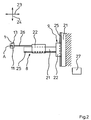
Figur 2- in einer Seitenansicht zwei senkrecht zueinander wirkende Antriebe zum Bewegen eines Punktes A der einen Schweißbacke der Figur 1 entlang einer umlaufenden Bahn;
- Figur 3
- in einer schematischen Darstellung den Umlauf zweier gegeneinander bewegbarer, entlang eines effektiven Siegelweges Zseff den Folienschlauch der Figur 1 verschweißenden Schweißbacken, sowie
Figur 4- in einer schematischen Darstellung den Schweißbackenumlauf entsprechend Figur 3, jedoch mit einem um eine Vorwärmstrecke und eine Kühlstrecke reduzierten effektiven Siegelweg.
- FIG. 1
- in a side view of a vertical bagging machine with mutually movable welding jaws of a transverse sealing station;
- FIG. 2
- in a side view two mutually perpendicular drives for moving a point A of a welding jaw of Figure 1 along a revolving path;
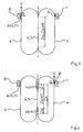
- FIG. 3
- in a schematic representation of the circulation of two mutually movable, along an effective seal path Zseff the film tube of Figure 1 welded welding jaws, and
- FIG. 4
- in a schematic representation of the welding jaw circulation according to Figure 3, but with a reduced by a preheating and a cooling line effective sealed path.
Bei einer vertikalen Schlauchbeutelmaschine 3 wird eine Folienbahn 14 mittels eines Abzuges 15 von einer Vorratsrolle 16 abgezogen, über eine Formschulter 17 gezogen und dabei zu einem Folienschlauch 7 geformt (Figur 1). Der Folienschlauch 7 wird mittels einer Längssiegeleinrichtung 18 in Transportrichtung 19 verschweißt und durch ein Füllrohr 20 befüllt. Zwei gegeneinander bewegbare, umlaufende Schweißbacken 1, 6 dienen dazu den Folienschlauch 7 quer zur Transportrichtung 19 mittels Quemähten 10 zu verschweißen. Eine Trenneinrichtung 11 in einer Schweißbacke 1 dient dazu, jeweils einen Schlauchbeutel 12 mit einer bestimmten Beutellänge vom Folienschlauch 7 abzutrennen.In a vertical tubular bag machine 3, a
Die Schweißbacken 1, 6 werden derart betrieben, dass sie gegenläufig umlaufen, um längs eines effektiven Siegelweges Zseff die Verschweißung des mit gleicher Geschwindigkeit wie die Schweißbacken 1, 6 nach unten bewegten Folienschlauch 7 auszuführen (Figur 3). Beide Schweißbacken 1, 6 werden dazu entlang einer jeweils geschlossenen Bahn 4 bewegt. Jede Bahn 4 weist einen geraden Abschnitt 5 auf, welcher zum Anliegen an dem zwischen den Schweißbacken 1, 6 zusammengedrückten Folienschlauch 7 vorgesehen ist. Dabei werden der Folienschlauch 7 und die Schweißbacken 1, 6 in Richtung des geraden Abschnittes 5 mit konstanter Geschwindigkeit weiterbewegt, um den Folienschlauch 7 durch die Wärmeinwirkung der Schweißbacken 1, 6 innerhalb einer Siegelzeit ts zu verschweißen.The
Es könnte aber auch ein Siegelweg Zs vorgegeben werden, welcher sich aus einer Vorwärmstrecke Zv für ein Vorwärmen des Gegenstandes mit vom Gegenstand beabstandeter Schweißbacke 1, dem eigentlichen, effektiven Siegelweg Zseff und einer Kühlstrecke Zk zum Abkühlen des Gegenstandes bei vom Gegenstand beabstandeter Schweißbacke 1, währenddessen Kühlluft von einem an der Schweißbacke 1 vorgesehenen Kühlluftauslass 13 auf den Gegenstand geblasen wird, zusammensetzt (Figur 4). Damit diese Umstellung der Siegelwege Zs mit allen Orts- und Zeitparametern in einfacher Weise möglich ist, wurde für die Vorwärmstrecke Zv, den effektiven Siegelweg Zseff und die Kühlstrecke Zk jeweils ein bezüglich seiner Länge und seinen Ortskoordinaten frei wählbarer, parallel zum geraden Abschnitt 5 verlaufender Abschnitt 4a, 5, 4b vorgesehen, auf dem sich der Bewegungspunkt A entlang bewegt. Dazu werden die Antriebe 8, 9 (Figur 2) derart betrieben, dass entlang einer Bahnkrümmung beide Antriebe 8, 9 gleichzeitig betrieben werden und entlang eines geraden Abschnittes 4a, 5, 4b nur der Antrieb 9 genutzt wird, damit einem Bewegungspunkt A der Schweißbacke 1, 6 in jedem die Bahn 4 beschreibenden Punkt frei ausgewählt, eine vorgegebene Geschwindigkeit V und eine vorgegebene Beschleunigung a in Richtung einer frei gewählten Bewegungsrichtung des Bewegungspunktes A zugeordnet wird. D. h. die geraden Abschnitte 4a, 5, 4b, sowie ihre genauen Längen und Ortskoordinaten können frei programmiert werden. An genau vorgegebenen Orten können also genau vorgegebene Geschwindigkeiten und, aus Gründen eines ruhigen Backenumlaufes, auch genau vorgegebene Beschleunigungen für die Schweißbacken 1, 6 vorgegeben werden. Auch die Rücksetzzeit zum erneuten Ansetzen der Schweißbacken 1, 6 an den Folienschlauch 7 und die Zykluszeit (Zeit für einen Backenumlauf) können frei ausgewählt werden. Eine entsprechende Software bringt die vorgewählten Parameter in die gewünschte Abhängigkeit und informiert über nicht zusammenpassende Eingaben.However, it would also be possible to specify a sealing path Zs, which consists of a preheating section Zv for preheating the article with the welding jaw 1 spaced apart from the object, the actual, effective sealing path Zseff and a cooling section Zk for cooling the article with the welding jaw 1 at a distance from the object Cooling air is blown from a provided on the welding jaw 1
Damit der Bewegungspunkt A, welcher mit einer Genauigkeit von 0,01 bis 0,1 mm hinsichtlich seiner Ortskoordinaten in den Richtungen 23, 24 vorgewählt werden kann, auch derart ortsgenau bewegt werden kann, sind zum Bewegen der Schweißbacken 1, 6 jeweils zwei als elektromagnetischer Linearantrieb, der nach dem Schwebebahnprinzip funktioniert, ausgestaltete, senkrecht zueinander wirkende Antriebe 8, 9 vorgesehen. Diese Antriebe 8, 9 sind mit einer Steuereinrichtung 27 verbunden, um den Bewegungspunkt A jeder Schweißbacke 1, 6 bezüglich seiner Ortskoordinaten mit einer koordinatenabhängigen Geschwindigkeit V und einer koordinatenabhängigen Beschleunigung a zu versehen. Dabei könnte auch allein aus den Geschwindigkeitswerten und den Beschleunigungswerten (Betrag und Richtung) auf die geänderten Ortskoordinaten (pro Zeiteinheit) geschlossen werden.So that the movement point A, which can be preselected with an accuracy of 0.01 to 0.1 mm with respect to its location coordinates in the
Zur Vermeidung irgendeiner Ortsungenauigkeit sind zum einen beide Antriebe 8, 9 getriebelos miteinander und mit einer Schweißbacke 1, 6 verbunden. Zum anderen sind ortsverändemde Elastizitäten dadurch vermieden, dass jede Schweißbacke 1, 6 über eine starre Verbindung 26 mit dem beweglichen Teil 22 des horizontal wirkenden Antriebs 8 verbunden ist, und dass das antreibende Teil 21 dieses Antriebs 8 mit dem in vertikaler Richtung beweglichen Teil 22 des anderen Antriebs 9 starr verbunden ist.To avoid any local inaccuracy, both
Die frei wählbaren Geschwindigkeits- und Beschleunigungswerte erlauben in jedem Punkt der Bahn 4 eine ideale Backenbewegung, auch bei relativ kompliziertem Bahnverlauf.
- 1
- Schweißbacke
- 2
- Quersiegelstation
- 3
- Schlauchbeutelmaschine
- 4
- Bahn
- 4a, 4b
Abschnitt der Bahn 4- 5
- gerader Abschnitt
- 6
- gegenläufige Schweißbacke
- 7
- Folienschlauch
- 8, 9
- Antrieb
- 10
- Quernaht
- 11
- Trenneinrichtung
- 12
- Schlauchbeutel
- 13
- Kühlluftauslass
- 14
- Folienbahn
- 15
- Abzug
- 16
- Vorratsrolle
- 17
- Formschulter
- 18
- Längssiegeleinrichtung
- 19
- Transportrichtung
- 20
- Füllrohr
- 21
- antreibendes Teil
- 22
- bewegliches Teil
- 23, 24
- Richtung
- 25
- Führung
- 26
- starre Verbindung
- 27
- Steuereinrichtung
- ts
- Siegelzeit
- Zs
- Siegelweg, technisch
- Zseff
- effektiver Siegelweg
- A
- Bewegungspunkt
- V
- Geschwindigkeit
- a
- Beschleunigung
- x, y
- Bahnkoordinaten
- 1
- welding jaw
- 2
- Cross-sealing station
- 3
- Fill and seal machine
- 4
- train
- 4a, 4b
- Section of the
track 4 - 5
- straight section
- 6
- opposite welding jaw
- 7
- film tube
- 8, 9
- drive
- 10
- cross seam
- 11
- separator
- 12
- tubular bag
- 13
- cooling air outlet
- 14
- sheet
- 15
- deduction
- 16
- supply roll
- 17
- forming shoulder
- 18
- Longitudinal sealing device
- 19
- transport direction
- 20
- filling pipe
- 21
- driving part
- 22
- moving part
- 23, 24
- direction
- 25
- guide
- 26
- rigid connection
- 27
- control device
- ts
- sealing time
- Zs
- Siegelweg, technical
- Zseff
- effective seal way
- A
- movement point
- V
- speed
- a
- acceleration
- x, y
- path coordinates
Claims (8)
- A method of moving a welding jaw (1, 6), in particular a welding jaw (1, 6) of a transverse sealing station (2) of a vertical bag-forming, -filling and -sealing machine (3), wherein the welding jaw (1, 6) is moved along a closed path (4), and the path (4) has a straight portion (5) which is provided for abutting against an article to be welded, in particular a film tube (7) which is compressed between the welding jaw (1) and a second welding jaw (6) extending in the opposite direction, wherein the article and the welding jaw (1, 6) are moved further at the same speed in the direction of the straight portion (5) in order to weld the article by the heat effect of the welding jaw (1, 6) within a welding time (ts), and wherein two drives (8, 9) are operated which move the welding jaw (1, 6) and which act in two different directions (23, 24) preferably extending at a right angle to each other, in order to achieve a circulation of the welding jaw (1, 6) within a cycle time (tz), wherein the drives (8, 9) provided are in the form of electromagnetic linear drives which operate in accordance with the suspension-railway principle and act at a right angle to each other and which are capable of being operated with a control device (27) in order to provide a movement point (A) with a co-ordinate-dependent speed (V) and a co-ordinate-dependent acceleration (a) with respect to its location co-ordinates, and the drives (8, 9) are operated in such a way that either both drives (8, 9) are operated at the same time or only one of the drives (8, 9) is used, characterized in that the movement point (A) of the welding jaw (1, 6) has associated with it at each point describing the path (4) in a freely selectable manner a pre-set speed (V) and a pre-set acceleration (a) in the direction of a freely selected movement direction of the movement point (A).
- A method according to Claim 1, characterized in that the welding jaw (1, 6) welds a film tube (7) by means of transverse seams (10), and a film bag (12) with a bag length (L) is separated in each case from the film tube (7) by means of separating device (11).
- A method according to Claim 1 or Claim 2, characterized in that the movement point (A) is pre-selected with an accuracy of from 0-01 to 0·1 mm with respect to its location co-ordinates in the directions (23, 24).
- A method according to Claim 1, Claim 2 or Claim 3, characterized in that a sealing path (Zs) is pre-set which is formed from a pre-heating stretch (Zv) for pre-heating the article or a stripping path for stripping the article with a welding jaw (1) arranged at a distance from the article, the actual, effective sealing path (Zseff) and optionally a cooling stretch (Zk) for cooling the article when the welding jaw (1) is situated at a distance from the article, during which cooling air is blown onto the article from a cooling-air outlet (13) provided on the welding jaw (1).
- A method according to Claim 4, characterized in that a portion (4a, 5, 4b), which is freely selectable with respect to its length and its location co-ordinates and extends parallel to the straight portion (5) and along which the movement point (A) moves, is provided in each case for the pre-heating stretch (Zv) or the stripping path, the effective sealing path (Zseff) and optionally the cooling stretch (Zk).
- An apparatus for performing the method according to Claim 1 and Claim 2, and optionally any one of Claims 3 to 5, wherein the apparatus is a vertical bag-forming, -filling and -sealing machine (3), wherein the welding jaw (1, 6) is moved along a closed path (4), and the path (4) has a straight portion (5) which is provided for abutting against an article to be welded, in particular a film tube (7) which is compressed between the welding jaw (1) and a second welding jaw (6) extending in the opposite direction, wherein the article and the welding jaw (1, 6) are moved further at the same speed in the direction of the straight portion (5) in order to weld the article by the heat effect of the welding jaw (1, 6) within a welding time (ts), and wherein two drives (8, 9) are operated which move the welding jaw (1, 6) and which act in two different directions (23, 24) preferably extending at a right angle to each other, in order to achieve a circulation of the welding jaw (1, 6) within a cycle time (tz), wherein the drives (8, 9) provided are in the form of electromagnetic linear drives which operate in accordance with the suspension-railway principle and act at a right angle to each other and which are capable of being operated with a control device (27) in order to provide a movement point (A) with a co-ordinate-dependent speed (V) and a co-ordinate-dependent acceleration (a) with respect to its location co-ordinates, and the drives (8, 9) are capable of being operated in such a way that either both drives (8, 9) are operated at the same time or only one of the drives (8, 9) is used, characterized in that the movement point (A) of the welding jaw (1, 6) can have associated with it at each point describing the path (4) in a freely selectable manner a pre-set speed (V) and a pre-set acceleration (a) in the direction of a freely selected movement direction of the movement point (A).
- An apparatus according to Claim 6, characterized in that the two drives (8, 9) are connected to each other and to the welding jaw (1, 6) without a gear mechanism.
- An apparatus according to Claim 7, characterized in that the welding jaw (1, 6) is connected by way of a rigid connexion (26) to the movable part (22) of a horizontally acting drive (8), and the driving part (21) of the said drive (8) is rigidly connected to the part (22) - movable in the vertical direction - of the other drive (9).
Priority Applications (1)
| Application Number | Priority Date | Filing Date | Title |
|---|---|---|---|
| PL05020645T PL1642700T3 (en) | 2004-09-28 | 2005-09-22 | Method and apparatus for moving a sealing jaw |
Applications Claiming Priority (1)
| Application Number | Priority Date | Filing Date | Title |
|---|---|---|---|
| DE102004046972A DE102004046972A1 (en) | 2004-09-28 | 2004-09-28 | Method and device for moving a welding jaw |
Publications (3)
| Publication Number | Publication Date |
|---|---|
| EP1642700A2 EP1642700A2 (en) | 2006-04-05 |
| EP1642700A3 EP1642700A3 (en) | 2006-06-21 |
| EP1642700B1 true EP1642700B1 (en) | 2008-01-09 |
Family
ID=35637118
Family Applications (1)
| Application Number | Title | Priority Date | Filing Date |
|---|---|---|---|
| EP05020645A Active EP1642700B1 (en) | 2004-09-28 | 2005-09-22 | Method and apparatus for moving a sealing jaw |
Country Status (5)
| Country | Link |
|---|---|
| EP (1) | EP1642700B1 (en) |
| AT (1) | ATE383237T1 (en) |
| DE (2) | DE102004046972A1 (en) |
| ES (1) | ES2299935T3 (en) |
| PL (1) | PL1642700T3 (en) |
Families Citing this family (7)
| Publication number | Priority date | Publication date | Assignee | Title |
|---|---|---|---|---|
| DE102006022946A1 (en) * | 2006-05-17 | 2007-11-22 | Rovema - Verpackungsmaschinen Gmbh | Vertical bagging machine comprises linear motor with primary and secondary part, where secondary part is held in arbor, such that arbors are provided as collective components, and primary part is held by mounting plate |
| DE102007003930B4 (en) * | 2007-01-26 | 2021-01-21 | Rovema Gmbh | Tubular bag machine |
| DE102007007691A1 (en) * | 2007-02-16 | 2008-08-21 | Rovema - Verpackungsmaschinen Gmbh | Bag forming, filling and sealing machine, has control device connected to drive for lifting and lowering bagging machine, and computing bake channel suitable for input during input of bag length and seal time |
| DE102015200780A1 (en) | 2015-01-20 | 2016-07-21 | Robert Bosch Gmbh | Device for sealing a packaging or packaging material |
| US10351283B2 (en) * | 2015-12-17 | 2019-07-16 | Khs Usa, Inc. | Magnetically operated sealing bar assembly for packaging machines |
| JP7212356B2 (en) | 2018-12-27 | 2023-01-25 | 株式会社イシダ | bag making and packaging machine |
| CN113830337B (en) * | 2021-10-12 | 2022-07-26 | 安徽采林间食品有限公司 | Small bag feeding type nut packaging machine and working method thereof |
Family Cites Families (9)
| Publication number | Priority date | Publication date | Assignee | Title |
|---|---|---|---|---|
| DE3545228A1 (en) * | 1985-12-20 | 1987-07-02 | Rovema Gmbh | PACKING MACHINE FOR THE PRODUCTION, FILLING AND SEALING OF BAGS |
| DE3907208A1 (en) * | 1988-10-18 | 1990-04-19 | Rovema Gmbh | METHOD AND DEVICE FOR CONTROLLING THE MOVEMENT OF CROSS-WELDING JAWS OF A TUBE BAG MACHINE |
| EP0765812B1 (en) * | 1991-10-03 | 2000-08-16 | ISHIDA CO., Ltd. | Transverse sealer for packaging machine |
| DE4425207B4 (en) * | 1994-07-16 | 2006-06-08 | Rovema - Verpackungsmaschinen Gmbh | Fill and seal machine |
| DE19535438A1 (en) * | 1995-09-23 | 1997-03-27 | Rovema Gmbh | Packaging device |
| DE19535510B4 (en) * | 1995-09-25 | 2006-06-08 | Rovema - Verpackungsmaschinen Gmbh | Closing device for a packaging process |
| JP3585638B2 (en) * | 1996-04-03 | 2004-11-04 | 三光機械株式会社 | Multiple automatic packing machine |
| DE19627892A1 (en) * | 1996-07-11 | 1998-01-15 | Rovema Gmbh | Tubular bag machine |
| DE19630420B4 (en) * | 1996-07-27 | 2007-06-14 | Rovema - Verpackungsmaschinen Gmbh | Method for operating a tubular bag machine |
-
2004
- 2004-09-28 DE DE102004046972A patent/DE102004046972A1/en not_active Withdrawn
-
2005
- 2005-09-22 PL PL05020645T patent/PL1642700T3/en unknown
- 2005-09-22 AT AT05020645T patent/ATE383237T1/en not_active IP Right Cessation
- 2005-09-22 DE DE502005002471T patent/DE502005002471D1/en active Active
- 2005-09-22 ES ES05020645T patent/ES2299935T3/en active Active
- 2005-09-22 EP EP05020645A patent/EP1642700B1/en active Active
Also Published As
| Publication number | Publication date |
|---|---|
| DE102004046972A1 (en) | 2006-04-13 |
| EP1642700A3 (en) | 2006-06-21 |
| PL1642700T3 (en) | 2008-06-30 |
| ATE383237T1 (en) | 2008-01-15 |
| ES2299935T3 (en) | 2008-06-01 |
| EP1642700A2 (en) | 2006-04-05 |
| DE502005002471D1 (en) | 2008-02-21 |
Similar Documents
| Publication | Publication Date | Title |
|---|---|---|
| EP1642700B1 (en) | Method and apparatus for moving a sealing jaw | |
| EP1642831B1 (en) | Method and apparatus for moving sealing jaws | |
| EP1645401A2 (en) | Process and device for positioning a sealing jaw | |
| DE4425207B4 (en) | Fill and seal machine | |
| EP2447041B1 (en) | Ultrasound heat sealing method with seal pressure regulation | |
| WO2005009664A1 (en) | Multi-head friction welding method and device for carrying out said method | |
| EP2447043B1 (en) | Method for the energy-efficient sealing of tubular web | |
| DE102007025786A1 (en) | Bag machine for producing combination of two connected bags, has drive, which open and closes transverse cheeks and another drive lift and lower transverse cheeks | |
| EP2024167A2 (en) | Device for welding a film web | |
| EP2480458A1 (en) | Forming shoulder and device for producing tubular bags | |
| EP0764580A1 (en) | Machine for making tubular bags | |
| DE10331360A1 (en) | Device for welding a film tube | |
| EP1640140A2 (en) | Method and device for moving a sealing jaw | |
| DE102016004180A1 (en) | Apparatus for ultrasonic welding | |
| DE102004049376B4 (en) | Method for generating a welding force | |
| CH703854A2 (en) | Deflagration truncated welding system comprises two mutually movable clamping systems for clamping, positioning and alignment of rails arranged on a common guide system and different unspecified components | |
| DE102007004140B4 (en) | Fill and seal machine | |
| EP1495976A1 (en) | Apparatus for welding a blown tubular film | |
| DE102007003930B4 (en) | Tubular bag machine | |
| DE102006025849A1 (en) | Welding device for foil path formed at tubular foil tube, has coupling unit moving transverse to moving direction of movable parts to lift, lower, open and close sealing jaws by relative movement of movable part and fixed part | |
| DE102004043096B4 (en) | Device for welding a film tube | |
| DE102004056690B4 (en) | Device for welding a film tube | |
| DE102007007691A1 (en) | Bag forming, filling and sealing machine, has control device connected to drive for lifting and lowering bagging machine, and computing bake channel suitable for input during input of bag length and seal time | |
| DE102006023003A1 (en) | Device has two welding jaws displaced towards each other to weld formed film web or tubular film, where each welding jaw is connected to separate jaw support, preferably by jaw holder as well as, one drive has two linear motors | |
| DE102005003783A1 (en) | Sheet/film tube cut-through device for vertical bag forming, filling and sealing machine, has operating unit operated for performing cut transverse to operating direction, where adjusting unit varies stroke of operation unit |
Legal Events
| Date | Code | Title | Description |
|---|---|---|---|
| PUAI | Public reference made under article 153(3) epc to a published international application that has entered the european phase |
Free format text: ORIGINAL CODE: 0009012 |
|
| AK | Designated contracting states |
Kind code of ref document: A2 Designated state(s): AT BE BG CH CY CZ DE DK EE ES FI FR GB GR HU IE IS IT LI LT LU LV MC NL PL PT RO SE SI SK TR |
|
| AX | Request for extension of the european patent |
Extension state: AL BA HR MK YU |
|
| PUAL | Search report despatched |
Free format text: ORIGINAL CODE: 0009013 |
|
| AK | Designated contracting states |
Kind code of ref document: A3 Designated state(s): AT BE BG CH CY CZ DE DK EE ES FI FR GB GR HU IE IS IT LI LT LU LV MC NL PL PT RO SE SI SK TR |
|
| AX | Request for extension of the european patent |
Extension state: AL BA HR MK YU |
|
| 17P | Request for examination filed |
Effective date: 20061201 |
|
| 17Q | First examination report despatched |
Effective date: 20070117 |
|
| AKX | Designation fees paid |
Designated state(s): AT BE BG CH CY CZ DE DK EE ES FI FR GB GR HU IE IS IT LI LT LU LV MC NL PL PT RO SE SI SK TR |
|
| GRAP | Despatch of communication of intention to grant a patent |
Free format text: ORIGINAL CODE: EPIDOSNIGR1 |
|
| GRAS | Grant fee paid |
Free format text: ORIGINAL CODE: EPIDOSNIGR3 |
|
| GRAA | (expected) grant |
Free format text: ORIGINAL CODE: 0009210 |
|
| AK | Designated contracting states |
Kind code of ref document: B1 Designated state(s): AT BE BG CH CY CZ DE DK EE ES FI FR GB GR HU IE IS IT LI LT LU LV MC NL PL PT RO SE SI SK TR |
|
| REG | Reference to a national code |
Ref country code: GB Ref legal event code: FG4D Free format text: NOT ENGLISH |
|
| REG | Reference to a national code |
Ref country code: CH Ref legal event code: EP |
|
| REG | Reference to a national code |
Ref country code: IE Ref legal event code: FG4D Free format text: LANGUAGE OF EP DOCUMENT: GERMAN |
|
| REF | Corresponds to: |
Ref document number: 502005002471 Country of ref document: DE Date of ref document: 20080221 Kind code of ref document: P |
|
| GBT | Gb: translation of ep patent filed (gb section 77(6)(a)/1977) |
Effective date: 20080403 |
|
| PG25 | Lapsed in a contracting state [announced via postgrant information from national office to epo] |
Ref country code: SI Free format text: LAPSE BECAUSE OF FAILURE TO SUBMIT A TRANSLATION OF THE DESCRIPTION OR TO PAY THE FEE WITHIN THE PRESCRIBED TIME-LIMIT Effective date: 20080109 |
|
| REG | Reference to a national code |
Ref country code: ES Ref legal event code: FG2A Ref document number: 2299935 Country of ref document: ES Kind code of ref document: T3 |
|
| REG | Reference to a national code |
Ref country code: PL Ref legal event code: T3 |
|
| PG25 | Lapsed in a contracting state [announced via postgrant information from national office to epo] |
Ref country code: FI Free format text: LAPSE BECAUSE OF FAILURE TO SUBMIT A TRANSLATION OF THE DESCRIPTION OR TO PAY THE FEE WITHIN THE PRESCRIBED TIME-LIMIT Effective date: 20080109 Ref country code: IS Free format text: LAPSE BECAUSE OF FAILURE TO SUBMIT A TRANSLATION OF THE DESCRIPTION OR TO PAY THE FEE WITHIN THE PRESCRIBED TIME-LIMIT Effective date: 20080509 Ref country code: LT Free format text: LAPSE BECAUSE OF FAILURE TO SUBMIT A TRANSLATION OF THE DESCRIPTION OR TO PAY THE FEE WITHIN THE PRESCRIBED TIME-LIMIT Effective date: 20080109 |
|
| ET | Fr: translation filed | ||
| PG25 | Lapsed in a contracting state [announced via postgrant information from national office to epo] |
Ref country code: BG Free format text: LAPSE BECAUSE OF FAILURE TO SUBMIT A TRANSLATION OF THE DESCRIPTION OR TO PAY THE FEE WITHIN THE PRESCRIBED TIME-LIMIT Effective date: 20080409 |
|
| PG25 | Lapsed in a contracting state [announced via postgrant information from national office to epo] |
Ref country code: PT Free format text: LAPSE BECAUSE OF FAILURE TO SUBMIT A TRANSLATION OF THE DESCRIPTION OR TO PAY THE FEE WITHIN THE PRESCRIBED TIME-LIMIT Effective date: 20080609 Ref country code: LV Free format text: LAPSE BECAUSE OF FAILURE TO SUBMIT A TRANSLATION OF THE DESCRIPTION OR TO PAY THE FEE WITHIN THE PRESCRIBED TIME-LIMIT Effective date: 20080109 |
|
| REG | Reference to a national code |
Ref country code: IE Ref legal event code: FD4D |
|
| PG25 | Lapsed in a contracting state [announced via postgrant information from national office to epo] |
Ref country code: SE Free format text: LAPSE BECAUSE OF FAILURE TO SUBMIT A TRANSLATION OF THE DESCRIPTION OR TO PAY THE FEE WITHIN THE PRESCRIBED TIME-LIMIT Effective date: 20080409 Ref country code: SK Free format text: LAPSE BECAUSE OF FAILURE TO SUBMIT A TRANSLATION OF THE DESCRIPTION OR TO PAY THE FEE WITHIN THE PRESCRIBED TIME-LIMIT Effective date: 20080109 Ref country code: DK Free format text: LAPSE BECAUSE OF FAILURE TO SUBMIT A TRANSLATION OF THE DESCRIPTION OR TO PAY THE FEE WITHIN THE PRESCRIBED TIME-LIMIT Effective date: 20080109 Ref country code: IE Free format text: LAPSE BECAUSE OF FAILURE TO SUBMIT A TRANSLATION OF THE DESCRIPTION OR TO PAY THE FEE WITHIN THE PRESCRIBED TIME-LIMIT Effective date: 20080109 |
|
| PLBE | No opposition filed within time limit |
Free format text: ORIGINAL CODE: 0009261 |
|
| STAA | Information on the status of an ep patent application or granted ep patent |
Free format text: STATUS: NO OPPOSITION FILED WITHIN TIME LIMIT |
|
| PG25 | Lapsed in a contracting state [announced via postgrant information from national office to epo] |
Ref country code: RO Free format text: LAPSE BECAUSE OF FAILURE TO SUBMIT A TRANSLATION OF THE DESCRIPTION OR TO PAY THE FEE WITHIN THE PRESCRIBED TIME-LIMIT Effective date: 20080109 |
|
| 26N | No opposition filed |
Effective date: 20081010 |
|
| PG25 | Lapsed in a contracting state [announced via postgrant information from national office to epo] |
Ref country code: MC Free format text: LAPSE BECAUSE OF NON-PAYMENT OF DUE FEES Effective date: 20080930 Ref country code: EE Free format text: LAPSE BECAUSE OF FAILURE TO SUBMIT A TRANSLATION OF THE DESCRIPTION OR TO PAY THE FEE WITHIN THE PRESCRIBED TIME-LIMIT Effective date: 20080109 |
|
| PG25 | Lapsed in a contracting state [announced via postgrant information from national office to epo] |
Ref country code: CY Free format text: LAPSE BECAUSE OF FAILURE TO SUBMIT A TRANSLATION OF THE DESCRIPTION OR TO PAY THE FEE WITHIN THE PRESCRIBED TIME-LIMIT Effective date: 20080109 |
|
| PG25 | Lapsed in a contracting state [announced via postgrant information from national office to epo] |
Ref country code: AT Free format text: LAPSE BECAUSE OF NON-PAYMENT OF DUE FEES Effective date: 20080922 |
|
| REG | Reference to a national code |
Ref country code: CH Ref legal event code: PL |
|
| PG25 | Lapsed in a contracting state [announced via postgrant information from national office to epo] |
Ref country code: HU Free format text: LAPSE BECAUSE OF FAILURE TO SUBMIT A TRANSLATION OF THE DESCRIPTION OR TO PAY THE FEE WITHIN THE PRESCRIBED TIME-LIMIT Effective date: 20080710 Ref country code: LU Free format text: LAPSE BECAUSE OF NON-PAYMENT OF DUE FEES Effective date: 20080922 |
|
| PG25 | Lapsed in a contracting state [announced via postgrant information from national office to epo] |
Ref country code: TR Free format text: LAPSE BECAUSE OF FAILURE TO SUBMIT A TRANSLATION OF THE DESCRIPTION OR TO PAY THE FEE WITHIN THE PRESCRIBED TIME-LIMIT Effective date: 20080109 |
|
| PG25 | Lapsed in a contracting state [announced via postgrant information from national office to epo] |
Ref country code: CH Free format text: LAPSE BECAUSE OF NON-PAYMENT OF DUE FEES Effective date: 20090930 Ref country code: GR Free format text: LAPSE BECAUSE OF FAILURE TO SUBMIT A TRANSLATION OF THE DESCRIPTION OR TO PAY THE FEE WITHIN THE PRESCRIBED TIME-LIMIT Effective date: 20080410 Ref country code: LI Free format text: LAPSE BECAUSE OF NON-PAYMENT OF DUE FEES Effective date: 20090930 |
|
| REG | Reference to a national code |
Ref country code: NL Ref legal event code: SD Effective date: 20110912 |
|
| REG | Reference to a national code |
Ref country code: DE Ref legal event code: R081 Ref document number: 502005002471 Country of ref document: DE Owner name: ROVEMA GMBH, DE Free format text: FORMER OWNER: ROVEMA VERPACKUNGSMASCHINEN GMBH, 35463 FERNWALD, DE Effective date: 20110915 Ref country code: DE Ref legal event code: R082 Ref document number: 502005002471 Country of ref document: DE Representative=s name: ADVOTEC. PATENT- UND RECHTSANWAELTE, DE Effective date: 20110915 |
|
| REG | Reference to a national code |
Ref country code: FR Ref legal event code: TP Owner name: ROVEMA GMBH, DE Effective date: 20111027 |
|
| REG | Reference to a national code |
Ref country code: GB Ref legal event code: 732E Free format text: REGISTERED BETWEEN 20111110 AND 20111116 |
|
| REG | Reference to a national code |
Ref country code: ES Ref legal event code: PC2A Owner name: ROVEMA GMBH Effective date: 20120511 |
|
| REG | Reference to a national code |
Ref country code: FR Ref legal event code: PLFP Year of fee payment: 12 |
|
| REG | Reference to a national code |
Ref country code: FR Ref legal event code: PLFP Year of fee payment: 13 |
|
| REG | Reference to a national code |
Ref country code: FR Ref legal event code: PLFP Year of fee payment: 14 |
|
| PGFP | Annual fee paid to national office [announced via postgrant information from national office to epo] |
Ref country code: DE Payment date: 20181122 Year of fee payment: 14 |
|
| REG | Reference to a national code |
Ref country code: DE Ref legal event code: R119 Ref document number: 502005002471 Country of ref document: DE |
|
| PG25 | Lapsed in a contracting state [announced via postgrant information from national office to epo] |
Ref country code: DE Free format text: LAPSE BECAUSE OF NON-PAYMENT OF DUE FEES Effective date: 20200401 |
|
| PGFP | Annual fee paid to national office [announced via postgrant information from national office to epo] |
Ref country code: GB Payment date: 20220927 Year of fee payment: 18 Ref country code: CZ Payment date: 20220912 Year of fee payment: 18 |
|
| PGFP | Annual fee paid to national office [announced via postgrant information from national office to epo] |
Ref country code: PL Payment date: 20220825 Year of fee payment: 18 Ref country code: FR Payment date: 20220920 Year of fee payment: 18 |
|
| PGFP | Annual fee paid to national office [announced via postgrant information from national office to epo] |
Ref country code: NL Payment date: 20230920 Year of fee payment: 19 |
|
| PGFP | Annual fee paid to national office [announced via postgrant information from national office to epo] |
Ref country code: BE Payment date: 20230918 Year of fee payment: 19 |
|
| PGFP | Annual fee paid to national office [announced via postgrant information from national office to epo] |
Ref country code: ES Payment date: 20231019 Year of fee payment: 19 |
|
| PGFP | Annual fee paid to national office [announced via postgrant information from national office to epo] |
Ref country code: IT Payment date: 20230929 Year of fee payment: 19 |