EP0765812B1 - Transverse sealer for packaging machine - Google Patents
Transverse sealer for packaging machine Download PDFInfo
- Publication number
- EP0765812B1 EP0765812B1 EP96202750A EP96202750A EP0765812B1 EP 0765812 B1 EP0765812 B1 EP 0765812B1 EP 96202750 A EP96202750 A EP 96202750A EP 96202750 A EP96202750 A EP 96202750A EP 0765812 B1 EP0765812 B1 EP 0765812B1
- Authority
- EP
- European Patent Office
- Prior art keywords
- transverse
- pair
- film
- transverse sealing
- bag
- Prior art date
- Legal status (The legal status is an assumption and is not a legal conclusion. Google has not performed a legal analysis and makes no representation as to the accuracy of the status listed.)
- Expired - Lifetime
Links
Images


Classifications
-
- B—PERFORMING OPERATIONS; TRANSPORTING
- B65—CONVEYING; PACKING; STORING; HANDLING THIN OR FILAMENTARY MATERIAL
- B65B—MACHINES, APPARATUS OR DEVICES FOR, OR METHODS OF, PACKAGING ARTICLES OR MATERIALS; UNPACKING
- B65B51/00—Devices for, or methods of, sealing or securing package folds or closures; Devices for gathering or twisting wrappers, or necks of bags
- B65B51/10—Applying or generating heat or pressure or combinations thereof
- B65B51/26—Devices specially adapted for producing transverse or longitudinal seams in webs or tubes
- B65B51/30—Devices, e.g. jaws, for applying pressure and heat, e.g. for subdividing filled tubes
- B65B51/306—Counter-rotating devices
-
- B—PERFORMING OPERATIONS; TRANSPORTING
- B29—WORKING OF PLASTICS; WORKING OF SUBSTANCES IN A PLASTIC STATE IN GENERAL
- B29C—SHAPING OR JOINING OF PLASTICS; SHAPING OF MATERIAL IN A PLASTIC STATE, NOT OTHERWISE PROVIDED FOR; AFTER-TREATMENT OF THE SHAPED PRODUCTS, e.g. REPAIRING
- B29C65/00—Joining or sealing of preformed parts, e.g. welding of plastics materials; Apparatus therefor
- B29C65/02—Joining or sealing of preformed parts, e.g. welding of plastics materials; Apparatus therefor by heating, with or without pressure
- B29C65/18—Joining or sealing of preformed parts, e.g. welding of plastics materials; Apparatus therefor by heating, with or without pressure using heated tools
-
- B—PERFORMING OPERATIONS; TRANSPORTING
- B29—WORKING OF PLASTICS; WORKING OF SUBSTANCES IN A PLASTIC STATE IN GENERAL
- B29C—SHAPING OR JOINING OF PLASTICS; SHAPING OF MATERIAL IN A PLASTIC STATE, NOT OTHERWISE PROVIDED FOR; AFTER-TREATMENT OF THE SHAPED PRODUCTS, e.g. REPAIRING
- B29C66/00—General aspects of processes or apparatus for joining preformed parts
- B29C66/01—General aspects dealing with the joint area or with the area to be joined
- B29C66/05—Particular design of joint configurations
- B29C66/10—Particular design of joint configurations particular design of the joint cross-sections
- B29C66/11—Joint cross-sections comprising a single joint-segment, i.e. one of the parts to be joined comprising a single joint-segment in the joint cross-section
- B29C66/112—Single lapped joints
- B29C66/1122—Single lap to lap joints, i.e. overlap joints
-
- B—PERFORMING OPERATIONS; TRANSPORTING
- B29—WORKING OF PLASTICS; WORKING OF SUBSTANCES IN A PLASTIC STATE IN GENERAL
- B29C—SHAPING OR JOINING OF PLASTICS; SHAPING OF MATERIAL IN A PLASTIC STATE, NOT OTHERWISE PROVIDED FOR; AFTER-TREATMENT OF THE SHAPED PRODUCTS, e.g. REPAIRING
- B29C66/00—General aspects of processes or apparatus for joining preformed parts
- B29C66/01—General aspects dealing with the joint area or with the area to be joined
- B29C66/346—Making joints having variable thicknesses in the joint area, e.g. by using jaws having an adapted configuration
-
- B—PERFORMING OPERATIONS; TRANSPORTING
- B29—WORKING OF PLASTICS; WORKING OF SUBSTANCES IN A PLASTIC STATE IN GENERAL
- B29C—SHAPING OR JOINING OF PLASTICS; SHAPING OF MATERIAL IN A PLASTIC STATE, NOT OTHERWISE PROVIDED FOR; AFTER-TREATMENT OF THE SHAPED PRODUCTS, e.g. REPAIRING
- B29C66/00—General aspects of processes or apparatus for joining preformed parts
- B29C66/40—General aspects of joining substantially flat articles, e.g. plates, sheets or web-like materials; Making flat seams in tubular or hollow articles; Joining single elements to substantially flat surfaces
- B29C66/41—Joining substantially flat articles ; Making flat seams in tubular or hollow articles
- B29C66/43—Joining a relatively small portion of the surface of said articles
- B29C66/431—Joining the articles to themselves
- B29C66/4312—Joining the articles to themselves for making flat seams in tubular or hollow articles, e.g. transversal seams
-
- B—PERFORMING OPERATIONS; TRANSPORTING
- B29—WORKING OF PLASTICS; WORKING OF SUBSTANCES IN A PLASTIC STATE IN GENERAL
- B29C—SHAPING OR JOINING OF PLASTICS; SHAPING OF MATERIAL IN A PLASTIC STATE, NOT OTHERWISE PROVIDED FOR; AFTER-TREATMENT OF THE SHAPED PRODUCTS, e.g. REPAIRING
- B29C66/00—General aspects of processes or apparatus for joining preformed parts
- B29C66/70—General aspects of processes or apparatus for joining preformed parts characterised by the composition, physical properties or the structure of the material of the parts to be joined; Joining with non-plastics material
- B29C66/73—General aspects of processes or apparatus for joining preformed parts characterised by the composition, physical properties or the structure of the material of the parts to be joined; Joining with non-plastics material characterised by the intensive physical properties of the material of the parts to be joined, by the optical properties of the material of the parts to be joined, by the extensive physical properties of the parts to be joined, by the state of the material of the parts to be joined or by the material of the parts to be joined being a thermoplastic or a thermoset
- B29C66/737—General aspects of processes or apparatus for joining preformed parts characterised by the composition, physical properties or the structure of the material of the parts to be joined; Joining with non-plastics material characterised by the intensive physical properties of the material of the parts to be joined, by the optical properties of the material of the parts to be joined, by the extensive physical properties of the parts to be joined, by the state of the material of the parts to be joined or by the material of the parts to be joined being a thermoplastic or a thermoset characterised by the state of the material of the parts to be joined
- B29C66/7373—Joining soiled or oxidised materials
-
- B—PERFORMING OPERATIONS; TRANSPORTING
- B29—WORKING OF PLASTICS; WORKING OF SUBSTANCES IN A PLASTIC STATE IN GENERAL
- B29C—SHAPING OR JOINING OF PLASTICS; SHAPING OF MATERIAL IN A PLASTIC STATE, NOT OTHERWISE PROVIDED FOR; AFTER-TREATMENT OF THE SHAPED PRODUCTS, e.g. REPAIRING
- B29C66/00—General aspects of processes or apparatus for joining preformed parts
- B29C66/80—General aspects of machine operations or constructions and parts thereof
- B29C66/81—General aspects of the pressing elements, i.e. the elements applying pressure on the parts to be joined in the area to be joined, e.g. the welding jaws or clamps
- B29C66/814—General aspects of the pressing elements, i.e. the elements applying pressure on the parts to be joined in the area to be joined, e.g. the welding jaws or clamps characterised by the design of the pressing elements, e.g. of the welding jaws or clamps
- B29C66/8141—General aspects of the pressing elements, i.e. the elements applying pressure on the parts to be joined in the area to be joined, e.g. the welding jaws or clamps characterised by the design of the pressing elements, e.g. of the welding jaws or clamps characterised by the surface geometry of the part of the pressing elements, e.g. welding jaws or clamps, coming into contact with the parts to be joined
- B29C66/81427—General aspects of the pressing elements, i.e. the elements applying pressure on the parts to be joined in the area to be joined, e.g. the welding jaws or clamps characterised by the design of the pressing elements, e.g. of the welding jaws or clamps characterised by the surface geometry of the part of the pressing elements, e.g. welding jaws or clamps, coming into contact with the parts to be joined comprising a single ridge, e.g. for making a weakening line; comprising a single tooth
-
- B—PERFORMING OPERATIONS; TRANSPORTING
- B29—WORKING OF PLASTICS; WORKING OF SUBSTANCES IN A PLASTIC STATE IN GENERAL
- B29C—SHAPING OR JOINING OF PLASTICS; SHAPING OF MATERIAL IN A PLASTIC STATE, NOT OTHERWISE PROVIDED FOR; AFTER-TREATMENT OF THE SHAPED PRODUCTS, e.g. REPAIRING
- B29C66/00—General aspects of processes or apparatus for joining preformed parts
- B29C66/80—General aspects of machine operations or constructions and parts thereof
- B29C66/81—General aspects of the pressing elements, i.e. the elements applying pressure on the parts to be joined in the area to be joined, e.g. the welding jaws or clamps
- B29C66/814—General aspects of the pressing elements, i.e. the elements applying pressure on the parts to be joined in the area to be joined, e.g. the welding jaws or clamps characterised by the design of the pressing elements, e.g. of the welding jaws or clamps
- B29C66/8141—General aspects of the pressing elements, i.e. the elements applying pressure on the parts to be joined in the area to be joined, e.g. the welding jaws or clamps characterised by the design of the pressing elements, e.g. of the welding jaws or clamps characterised by the surface geometry of the part of the pressing elements, e.g. welding jaws or clamps, coming into contact with the parts to be joined
- B29C66/81431—General aspects of the pressing elements, i.e. the elements applying pressure on the parts to be joined in the area to be joined, e.g. the welding jaws or clamps characterised by the design of the pressing elements, e.g. of the welding jaws or clamps characterised by the surface geometry of the part of the pressing elements, e.g. welding jaws or clamps, coming into contact with the parts to be joined comprising a single cavity, e.g. a groove
-
- B—PERFORMING OPERATIONS; TRANSPORTING
- B29—WORKING OF PLASTICS; WORKING OF SUBSTANCES IN A PLASTIC STATE IN GENERAL
- B29C—SHAPING OR JOINING OF PLASTICS; SHAPING OF MATERIAL IN A PLASTIC STATE, NOT OTHERWISE PROVIDED FOR; AFTER-TREATMENT OF THE SHAPED PRODUCTS, e.g. REPAIRING
- B29C66/00—General aspects of processes or apparatus for joining preformed parts
- B29C66/80—General aspects of machine operations or constructions and parts thereof
- B29C66/81—General aspects of the pressing elements, i.e. the elements applying pressure on the parts to be joined in the area to be joined, e.g. the welding jaws or clamps
- B29C66/814—General aspects of the pressing elements, i.e. the elements applying pressure on the parts to be joined in the area to be joined, e.g. the welding jaws or clamps characterised by the design of the pressing elements, e.g. of the welding jaws or clamps
- B29C66/8145—General aspects of the pressing elements, i.e. the elements applying pressure on the parts to be joined in the area to be joined, e.g. the welding jaws or clamps characterised by the design of the pressing elements, e.g. of the welding jaws or clamps characterised by the constructional aspects of the pressing elements, e.g. of the welding jaws or clamps
- B29C66/81459—General aspects of the pressing elements, i.e. the elements applying pressure on the parts to be joined in the area to be joined, e.g. the welding jaws or clamps characterised by the design of the pressing elements, e.g. of the welding jaws or clamps characterised by the constructional aspects of the pressing elements, e.g. of the welding jaws or clamps being a filled deformable bladder, e.g. bladder filled with oil, with granules or with a meltable solid material
-
- B—PERFORMING OPERATIONS; TRANSPORTING
- B29—WORKING OF PLASTICS; WORKING OF SUBSTANCES IN A PLASTIC STATE IN GENERAL
- B29C—SHAPING OR JOINING OF PLASTICS; SHAPING OF MATERIAL IN A PLASTIC STATE, NOT OTHERWISE PROVIDED FOR; AFTER-TREATMENT OF THE SHAPED PRODUCTS, e.g. REPAIRING
- B29C66/00—General aspects of processes or apparatus for joining preformed parts
- B29C66/80—General aspects of machine operations or constructions and parts thereof
- B29C66/81—General aspects of the pressing elements, i.e. the elements applying pressure on the parts to be joined in the area to be joined, e.g. the welding jaws or clamps
- B29C66/816—General aspects of the pressing elements, i.e. the elements applying pressure on the parts to be joined in the area to be joined, e.g. the welding jaws or clamps characterised by the mounting of the pressing elements, e.g. of the welding jaws or clamps
- B29C66/8161—General aspects of the pressing elements, i.e. the elements applying pressure on the parts to be joined in the area to be joined, e.g. the welding jaws or clamps characterised by the mounting of the pressing elements, e.g. of the welding jaws or clamps said pressing elements being supported or backed-up by springs or by resilient material
- B29C66/81611—General aspects of the pressing elements, i.e. the elements applying pressure on the parts to be joined in the area to be joined, e.g. the welding jaws or clamps characterised by the mounting of the pressing elements, e.g. of the welding jaws or clamps said pressing elements being supported or backed-up by springs or by resilient material by resilient material
-
- B—PERFORMING OPERATIONS; TRANSPORTING
- B29—WORKING OF PLASTICS; WORKING OF SUBSTANCES IN A PLASTIC STATE IN GENERAL
- B29C—SHAPING OR JOINING OF PLASTICS; SHAPING OF MATERIAL IN A PLASTIC STATE, NOT OTHERWISE PROVIDED FOR; AFTER-TREATMENT OF THE SHAPED PRODUCTS, e.g. REPAIRING
- B29C66/00—General aspects of processes or apparatus for joining preformed parts
- B29C66/80—General aspects of machine operations or constructions and parts thereof
- B29C66/82—Pressure application arrangements, e.g. transmission or actuating mechanisms for joining tools or clamps
- B29C66/822—Transmission mechanisms
- B29C66/8221—Scissor or lever mechanisms, i.e. involving a pivot point
-
- B—PERFORMING OPERATIONS; TRANSPORTING
- B29—WORKING OF PLASTICS; WORKING OF SUBSTANCES IN A PLASTIC STATE IN GENERAL
- B29C—SHAPING OR JOINING OF PLASTICS; SHAPING OF MATERIAL IN A PLASTIC STATE, NOT OTHERWISE PROVIDED FOR; AFTER-TREATMENT OF THE SHAPED PRODUCTS, e.g. REPAIRING
- B29C66/00—General aspects of processes or apparatus for joining preformed parts
- B29C66/80—General aspects of machine operations or constructions and parts thereof
- B29C66/82—Pressure application arrangements, e.g. transmission or actuating mechanisms for joining tools or clamps
- B29C66/822—Transmission mechanisms
- B29C66/8222—Pinion or rack mechanisms
-
- B—PERFORMING OPERATIONS; TRANSPORTING
- B29—WORKING OF PLASTICS; WORKING OF SUBSTANCES IN A PLASTIC STATE IN GENERAL
- B29C—SHAPING OR JOINING OF PLASTICS; SHAPING OF MATERIAL IN A PLASTIC STATE, NOT OTHERWISE PROVIDED FOR; AFTER-TREATMENT OF THE SHAPED PRODUCTS, e.g. REPAIRING
- B29C66/00—General aspects of processes or apparatus for joining preformed parts
- B29C66/80—General aspects of machine operations or constructions and parts thereof
- B29C66/82—Pressure application arrangements, e.g. transmission or actuating mechanisms for joining tools or clamps
- B29C66/822—Transmission mechanisms
- B29C66/8223—Worm or spindle mechanisms
-
- B—PERFORMING OPERATIONS; TRANSPORTING
- B29—WORKING OF PLASTICS; WORKING OF SUBSTANCES IN A PLASTIC STATE IN GENERAL
- B29C—SHAPING OR JOINING OF PLASTICS; SHAPING OF MATERIAL IN A PLASTIC STATE, NOT OTHERWISE PROVIDED FOR; AFTER-TREATMENT OF THE SHAPED PRODUCTS, e.g. REPAIRING
- B29C66/00—General aspects of processes or apparatus for joining preformed parts
- B29C66/80—General aspects of machine operations or constructions and parts thereof
- B29C66/82—Pressure application arrangements, e.g. transmission or actuating mechanisms for joining tools or clamps
- B29C66/822—Transmission mechanisms
- B29C66/8226—Cam mechanisms; Wedges; Eccentric mechanisms
-
- B—PERFORMING OPERATIONS; TRANSPORTING
- B29—WORKING OF PLASTICS; WORKING OF SUBSTANCES IN A PLASTIC STATE IN GENERAL
- B29C—SHAPING OR JOINING OF PLASTICS; SHAPING OF MATERIAL IN A PLASTIC STATE, NOT OTHERWISE PROVIDED FOR; AFTER-TREATMENT OF THE SHAPED PRODUCTS, e.g. REPAIRING
- B29C66/00—General aspects of processes or apparatus for joining preformed parts
- B29C66/80—General aspects of machine operations or constructions and parts thereof
- B29C66/82—Pressure application arrangements, e.g. transmission or actuating mechanisms for joining tools or clamps
- B29C66/824—Actuating mechanisms
- B29C66/8242—Pneumatic or hydraulic drives
-
- B—PERFORMING OPERATIONS; TRANSPORTING
- B29—WORKING OF PLASTICS; WORKING OF SUBSTANCES IN A PLASTIC STATE IN GENERAL
- B29C—SHAPING OR JOINING OF PLASTICS; SHAPING OF MATERIAL IN A PLASTIC STATE, NOT OTHERWISE PROVIDED FOR; AFTER-TREATMENT OF THE SHAPED PRODUCTS, e.g. REPAIRING
- B29C66/00—General aspects of processes or apparatus for joining preformed parts
- B29C66/80—General aspects of machine operations or constructions and parts thereof
- B29C66/82—Pressure application arrangements, e.g. transmission or actuating mechanisms for joining tools or clamps
- B29C66/824—Actuating mechanisms
- B29C66/8246—Servomechanisms, e.g. servomotors
-
- B—PERFORMING OPERATIONS; TRANSPORTING
- B29—WORKING OF PLASTICS; WORKING OF SUBSTANCES IN A PLASTIC STATE IN GENERAL
- B29C—SHAPING OR JOINING OF PLASTICS; SHAPING OF MATERIAL IN A PLASTIC STATE, NOT OTHERWISE PROVIDED FOR; AFTER-TREATMENT OF THE SHAPED PRODUCTS, e.g. REPAIRING
- B29C66/00—General aspects of processes or apparatus for joining preformed parts
- B29C66/80—General aspects of machine operations or constructions and parts thereof
- B29C66/83—General aspects of machine operations or constructions and parts thereof characterised by the movement of the joining or pressing tools
- B29C66/834—General aspects of machine operations or constructions and parts thereof characterised by the movement of the joining or pressing tools moving with the parts to be joined
- B29C66/8351—Jaws mounted on rollers, cylinders, drums, bands, belts or chains; Flying jaws
- B29C66/83541—Jaws mounted on rollers, cylinders, drums, bands, belts or chains; Flying jaws flying jaws, e.g. jaws mounted on crank mechanisms or following a hand over hand movement
- B29C66/83543—Jaws mounted on rollers, cylinders, drums, bands, belts or chains; Flying jaws flying jaws, e.g. jaws mounted on crank mechanisms or following a hand over hand movement cooperating flying jaws
-
- B—PERFORMING OPERATIONS; TRANSPORTING
- B29—WORKING OF PLASTICS; WORKING OF SUBSTANCES IN A PLASTIC STATE IN GENERAL
- B29C—SHAPING OR JOINING OF PLASTICS; SHAPING OF MATERIAL IN A PLASTIC STATE, NOT OTHERWISE PROVIDED FOR; AFTER-TREATMENT OF THE SHAPED PRODUCTS, e.g. REPAIRING
- B29C66/00—General aspects of processes or apparatus for joining preformed parts
- B29C66/80—General aspects of machine operations or constructions and parts thereof
- B29C66/84—Specific machine types or machines suitable for specific applications
- B29C66/849—Packaging machines
- B29C66/8491—Packaging machines welding through a filled container, e.g. tube or bag
-
- B—PERFORMING OPERATIONS; TRANSPORTING
- B29—WORKING OF PLASTICS; WORKING OF SUBSTANCES IN A PLASTIC STATE IN GENERAL
- B29C—SHAPING OR JOINING OF PLASTICS; SHAPING OF MATERIAL IN A PLASTIC STATE, NOT OTHERWISE PROVIDED FOR; AFTER-TREATMENT OF THE SHAPED PRODUCTS, e.g. REPAIRING
- B29C66/00—General aspects of processes or apparatus for joining preformed parts
- B29C66/90—Measuring or controlling the joining process
- B29C66/92—Measuring or controlling the joining process by measuring or controlling the pressure, the force, the mechanical power or the displacement of the joining tools
- B29C66/924—Measuring or controlling the joining process by measuring or controlling the pressure, the force, the mechanical power or the displacement of the joining tools by controlling or regulating the pressure, the force, the mechanical power or the displacement of the joining tools
- B29C66/9241—Measuring or controlling the joining process by measuring or controlling the pressure, the force, the mechanical power or the displacement of the joining tools by controlling or regulating the pressure, the force, the mechanical power or the displacement of the joining tools by controlling or regulating the pressure, the force or the mechanical power
-
- B—PERFORMING OPERATIONS; TRANSPORTING
- B29—WORKING OF PLASTICS; WORKING OF SUBSTANCES IN A PLASTIC STATE IN GENERAL
- B29C—SHAPING OR JOINING OF PLASTICS; SHAPING OF MATERIAL IN A PLASTIC STATE, NOT OTHERWISE PROVIDED FOR; AFTER-TREATMENT OF THE SHAPED PRODUCTS, e.g. REPAIRING
- B29C66/00—General aspects of processes or apparatus for joining preformed parts
- B29C66/90—Measuring or controlling the joining process
- B29C66/92—Measuring or controlling the joining process by measuring or controlling the pressure, the force, the mechanical power or the displacement of the joining tools
- B29C66/924—Measuring or controlling the joining process by measuring or controlling the pressure, the force, the mechanical power or the displacement of the joining tools by controlling or regulating the pressure, the force, the mechanical power or the displacement of the joining tools
- B29C66/9261—Measuring or controlling the joining process by measuring or controlling the pressure, the force, the mechanical power or the displacement of the joining tools by controlling or regulating the pressure, the force, the mechanical power or the displacement of the joining tools by controlling or regulating the displacement of the joining tools
- B29C66/92611—Measuring or controlling the joining process by measuring or controlling the pressure, the force, the mechanical power or the displacement of the joining tools by controlling or regulating the pressure, the force, the mechanical power or the displacement of the joining tools by controlling or regulating the displacement of the joining tools by controlling or regulating the gap between the joining tools
- B29C66/92615—Measuring or controlling the joining process by measuring or controlling the pressure, the force, the mechanical power or the displacement of the joining tools by controlling or regulating the pressure, the force, the mechanical power or the displacement of the joining tools by controlling or regulating the displacement of the joining tools by controlling or regulating the gap between the joining tools the gap being non-constant over time
-
- B—PERFORMING OPERATIONS; TRANSPORTING
- B29—WORKING OF PLASTICS; WORKING OF SUBSTANCES IN A PLASTIC STATE IN GENERAL
- B29C—SHAPING OR JOINING OF PLASTICS; SHAPING OF MATERIAL IN A PLASTIC STATE, NOT OTHERWISE PROVIDED FOR; AFTER-TREATMENT OF THE SHAPED PRODUCTS, e.g. REPAIRING
- B29C66/00—General aspects of processes or apparatus for joining preformed parts
- B29C66/90—Measuring or controlling the joining process
- B29C66/93—Measuring or controlling the joining process by measuring or controlling the speed
- B29C66/934—Measuring or controlling the joining process by measuring or controlling the speed by controlling or regulating the speed
- B29C66/93431—Measuring or controlling the joining process by measuring or controlling the speed by controlling or regulating the speed the speed being kept constant over time
-
- B—PERFORMING OPERATIONS; TRANSPORTING
- B29—WORKING OF PLASTICS; WORKING OF SUBSTANCES IN A PLASTIC STATE IN GENERAL
- B29C—SHAPING OR JOINING OF PLASTICS; SHAPING OF MATERIAL IN A PLASTIC STATE, NOT OTHERWISE PROVIDED FOR; AFTER-TREATMENT OF THE SHAPED PRODUCTS, e.g. REPAIRING
- B29C66/00—General aspects of processes or apparatus for joining preformed parts
- B29C66/90—Measuring or controlling the joining process
- B29C66/93—Measuring or controlling the joining process by measuring or controlling the speed
- B29C66/934—Measuring or controlling the joining process by measuring or controlling the speed by controlling or regulating the speed
- B29C66/93451—Measuring or controlling the joining process by measuring or controlling the speed by controlling or regulating the speed by controlling or regulating the rotational speed, i.e. the speed of revolution
-
- B—PERFORMING OPERATIONS; TRANSPORTING
- B65—CONVEYING; PACKING; STORING; HANDLING THIN OR FILAMENTARY MATERIAL
- B65B—MACHINES, APPARATUS OR DEVICES FOR, OR METHODS OF, PACKAGING ARTICLES OR MATERIALS; UNPACKING
- B65B9/00—Enclosing successive articles, or quantities of material, e.g. liquids or semiliquids, in flat, folded, or tubular webs of flexible sheet material; Subdividing filled flexible tubes to form packages
- B65B9/10—Enclosing successive articles, or quantities of material, in preformed tubular webs, or in webs formed into tubes around filling nozzles, e.g. extruded tubular webs
- B65B9/20—Enclosing successive articles, or quantities of material, in preformed tubular webs, or in webs formed into tubes around filling nozzles, e.g. extruded tubular webs the webs being formed into tubes in situ around the filling nozzles
- B65B9/2007—Means for stripping or squeezing filled tubes prior to sealing to remove air or products from sealing area
-
- B—PERFORMING OPERATIONS; TRANSPORTING
- B65—CONVEYING; PACKING; STORING; HANDLING THIN OR FILAMENTARY MATERIAL
- B65B—MACHINES, APPARATUS OR DEVICES FOR, OR METHODS OF, PACKAGING ARTICLES OR MATERIALS; UNPACKING
- B65B9/00—Enclosing successive articles, or quantities of material, e.g. liquids or semiliquids, in flat, folded, or tubular webs of flexible sheet material; Subdividing filled flexible tubes to form packages
- B65B9/10—Enclosing successive articles, or quantities of material, in preformed tubular webs, or in webs formed into tubes around filling nozzles, e.g. extruded tubular webs
- B65B9/20—Enclosing successive articles, or quantities of material, in preformed tubular webs, or in webs formed into tubes around filling nozzles, e.g. extruded tubular webs the webs being formed into tubes in situ around the filling nozzles
- B65B9/2014—Tube advancing means
- B65B9/2028—Rollers or belts
-
- B—PERFORMING OPERATIONS; TRANSPORTING
- B65—CONVEYING; PACKING; STORING; HANDLING THIN OR FILAMENTARY MATERIAL
- B65B—MACHINES, APPARATUS OR DEVICES FOR, OR METHODS OF, PACKAGING ARTICLES OR MATERIALS; UNPACKING
- B65B9/00—Enclosing successive articles, or quantities of material, e.g. liquids or semiliquids, in flat, folded, or tubular webs of flexible sheet material; Subdividing filled flexible tubes to form packages
- B65B9/10—Enclosing successive articles, or quantities of material, in preformed tubular webs, or in webs formed into tubes around filling nozzles, e.g. extruded tubular webs
- B65B9/20—Enclosing successive articles, or quantities of material, in preformed tubular webs, or in webs formed into tubes around filling nozzles, e.g. extruded tubular webs the webs being formed into tubes in situ around the filling nozzles
- B65B9/213—Enclosing successive articles, or quantities of material, in preformed tubular webs, or in webs formed into tubes around filling nozzles, e.g. extruded tubular webs the webs being formed into tubes in situ around the filling nozzles the web having intermittent motion
-
- B—PERFORMING OPERATIONS; TRANSPORTING
- B29—WORKING OF PLASTICS; WORKING OF SUBSTANCES IN A PLASTIC STATE IN GENERAL
- B29C—SHAPING OR JOINING OF PLASTICS; SHAPING OF MATERIAL IN A PLASTIC STATE, NOT OTHERWISE PROVIDED FOR; AFTER-TREATMENT OF THE SHAPED PRODUCTS, e.g. REPAIRING
- B29C66/00—General aspects of processes or apparatus for joining preformed parts
- B29C66/80—General aspects of machine operations or constructions and parts thereof
- B29C66/81—General aspects of the pressing elements, i.e. the elements applying pressure on the parts to be joined in the area to be joined, e.g. the welding jaws or clamps
- B29C66/812—General aspects of the pressing elements, i.e. the elements applying pressure on the parts to be joined in the area to be joined, e.g. the welding jaws or clamps characterised by the composition, by the structure, by the intensive physical properties or by the optical properties of the material constituting the pressing elements, e.g. constituting the welding jaws or clamps
- B29C66/8122—General aspects of the pressing elements, i.e. the elements applying pressure on the parts to be joined in the area to be joined, e.g. the welding jaws or clamps characterised by the composition, by the structure, by the intensive physical properties or by the optical properties of the material constituting the pressing elements, e.g. constituting the welding jaws or clamps characterised by the composition of the material constituting the pressing elements, e.g. constituting the welding jaws or clamps
-
- B—PERFORMING OPERATIONS; TRANSPORTING
- B29—WORKING OF PLASTICS; WORKING OF SUBSTANCES IN A PLASTIC STATE IN GENERAL
- B29C—SHAPING OR JOINING OF PLASTICS; SHAPING OF MATERIAL IN A PLASTIC STATE, NOT OTHERWISE PROVIDED FOR; AFTER-TREATMENT OF THE SHAPED PRODUCTS, e.g. REPAIRING
- B29C66/00—General aspects of processes or apparatus for joining preformed parts
- B29C66/80—General aspects of machine operations or constructions and parts thereof
- B29C66/81—General aspects of the pressing elements, i.e. the elements applying pressure on the parts to be joined in the area to be joined, e.g. the welding jaws or clamps
- B29C66/814—General aspects of the pressing elements, i.e. the elements applying pressure on the parts to be joined in the area to be joined, e.g. the welding jaws or clamps characterised by the design of the pressing elements, e.g. of the welding jaws or clamps
- B29C66/8141—General aspects of the pressing elements, i.e. the elements applying pressure on the parts to be joined in the area to be joined, e.g. the welding jaws or clamps characterised by the design of the pressing elements, e.g. of the welding jaws or clamps characterised by the surface geometry of the part of the pressing elements, e.g. welding jaws or clamps, coming into contact with the parts to be joined
- B29C66/81411—General aspects of the pressing elements, i.e. the elements applying pressure on the parts to be joined in the area to be joined, e.g. the welding jaws or clamps characterised by the design of the pressing elements, e.g. of the welding jaws or clamps characterised by the surface geometry of the part of the pressing elements, e.g. welding jaws or clamps, coming into contact with the parts to be joined characterised by its cross-section, e.g. transversal or longitudinal, being non-flat
- B29C66/81415—General aspects of the pressing elements, i.e. the elements applying pressure on the parts to be joined in the area to be joined, e.g. the welding jaws or clamps characterised by the design of the pressing elements, e.g. of the welding jaws or clamps characterised by the surface geometry of the part of the pressing elements, e.g. welding jaws or clamps, coming into contact with the parts to be joined characterised by its cross-section, e.g. transversal or longitudinal, being non-flat being bevelled
- B29C66/81417—General aspects of the pressing elements, i.e. the elements applying pressure on the parts to be joined in the area to be joined, e.g. the welding jaws or clamps characterised by the design of the pressing elements, e.g. of the welding jaws or clamps characterised by the surface geometry of the part of the pressing elements, e.g. welding jaws or clamps, coming into contact with the parts to be joined characterised by its cross-section, e.g. transversal or longitudinal, being non-flat being bevelled being V-shaped
Definitions
- This invention relates to a transverse thermal sealer for sealing a packaging material used in a packaging machine for concurrently filling a bag with articles such as foods and making a packaged product.
- a bag-making packaging machine for concurrently forming a bag, filling it with articles such as foods and making it into a packaged product such as a so-called pillow-type packaging machine, is adapted to seal the mutually superposed longitudinal side edges of a belt-like elongated packaging material (hereinafter referred to as a film) while this film is being transformed into the shape of a bag by means of a former, and to thereafter transversely seal the bottom of the film, while the tubularly formed film is being pulled, by means of a pair of transverse thermal sealing means disposed below the outlet of the filling cylinder used for filling the tubular film with articles to be packaged. Since such a packaging machine is capable of simultaneously and continuously forming bags and filling them with articles to be packaged, it is considered an apparatus with high workability.
- a belt-like elongated packaging material hereinafter referred to as a film
- Japanese Patent Publication Tokkai 235006/87 disclosed an apparatus of the so-called rotary driving type adapted to cause the heating surfaces of its transverse sealing means to contact the film while the transverse sealing means are moved linearly in the direction in which the film is being pulled, such that a sufficiently long time can be spent for the transverse sealing process even if the period of cyclic packaging operation is shortened.
- this apparatus makes use of D-shaped grooves to guide these means, while causing them to undergo a cyclic motion.
- their linear trajectory and the compressive force between them are uniquely determined, and the film may be subjected to an unreasonable force from them, depending on the thickness, material property and/or width of the film. As a result, the film may be damaged, or the apparatus may fail to reliably perform a transverse sealing process.
- Packaging machines of the so-called intermittent driving type are also known. They are structurally simpler, although disadvantageous from the point of view of reducing the period of cyclic motion, and are characterized as pulling the film intermittently and carrying out the transverse sealing while the film is stopped.
- the method of using a hydraulic (oil-pressure) cylinder has been known in this connection for compressing the transverse sealing means against each other and adjusting the compressive force between them by controlling this pressure cylinder.
- Such a cylinder tends to make the apparatus bigger as a whole, and there arises the problem of keeping the oil for the cylinder away from the articles to be packaged.
- the present invention has been devised to substantially eliminate the discussed problems and is intended to provide an improved sealer and a packing machine, wherein the compressive force with which the transverse sealing means sandwich the film there between during thermal sealing to seal the bag can be adjusted to a predetermined level in dependence on the thickness, width and material property of the film which eventually forms the bag, which is assembled compact and which is capable of eliminating any possible contamination of articles to be filled in the bag which would otherwise result from the use of oil.
- transverse sealer for a packing machine for sealing a bag in a transverse direction after said bag has been filled with articles to be packaged, said bag being made from a belt-like elongated film moving on a transportation path in a film-transporting direction, said transverse direction being transverse to said film-transporting direction, said transverse sealer comprising:
- the compression adjusting means comprises an approach-separation motor for driving the pair of transverse sealing means in the approach-separation direction; and a control means for causing the approach-separation motor to rotate at a specified torque while the pair of transverse sealing means sandwich therebetween the film at the specified seal position.
- the compressive force exerted by the transverse sealing means on the bag being sealed can be maintained at the specified level and, therefore, a proper thermal seal appropriate to the thickness, width and/or material property of the film used to form the bag can be accomplished.
- the motor since the motor supersedes the hydraulic cylinder hitherto used in the prior art machine, the machine as a whole can be assembled compact in size and is substantially free from any possibility that the articles to be filled in the bag may be contaminated with oil.
- the compression adjusting means comprises a pair of mobile frames movable in an approach-separation direction in which the pair of transverse sealing means moves towards and away from each other, each supporting one of the transverse sealing means and receiving the reaction force to the compressive force, and a linear-to-rotary motion conversion means for converting the relative motion between the pair of mobile frames due to the reaction force into a rotary motion.
- the approach-separation motor is operable to move the pair of mobile frames towards and away from each other in the approach-separation direction through the linear-to-rotary motion conversion means.
- At least one of the pair of transverse sealing means has attached thereto a returning means for pressing the one transverse sealing means in the direction towards the other of the pair of transverse sealing means by a restorative elastic force proportional to a strain of the returning means.
- the compression adjusting means is operable to cause the pair of transverse sealing means to thermally seal the bag while the bag being transported is held still.
- Fig. 1 is a diagonal view of a pillow-type packaging machine with a transverse sealer according to a first embodiment of the present invention.
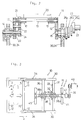
- Fig. 2 is a frontal sectional view of the arm rotation mechanism of the sealer of Fig. 1.
- Fig. 3 is a structural diagram showing the mechanism for moving the axis of the arm in the sealer of Fig. 1.
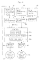
- Fig. 4 is a block diagram of an example of operation control for the sealer of Fig. 1.
- Figs. 5a and 5b are timing diagrams for the basic transverse sealing mode of operation of the sealer of Fig. 1.
- Figs. 6a and 6b are timing diagrams for the end acceleration mode of transverse sealing operation of the sealer of Fig. 1.
- Figs. 7a and 7b are timing diagrams for the transverse mode of operation with stripping by the sealer of Fig. 1.
- Figs. 8a and 8b are timing diagrams for the end acceleration mode of transverse sealing operation with stripping by the sealer of Fig. 1.
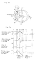
- Fig. 9 is a frontal sectional view of an essential portion of a transverse sealing mechanism according to a second embodiment of the present invention.
- Fig. 10 is a diagram for showing the principles of the transverse sealing mechanism of Fig. 9.
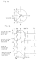
- Fig. 11 is a schematic structural diagram showing the structure of transverse seal jaw which is a variation on the second embodiment of the invention.
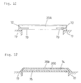
- Fig. 12 is a schematic structural diagram showing the structure of transverse seal jaw which is another variation on the second embodiment of the invention.
- Fig. 1 shows a pillow-type packaging machine equipped with a transverse sealing mechanism according to a first embodiment of the invention.
- This packaging machine is of the type without a filling cylinder and is structured such that after a belt-like film S is bent into a tubular form by means of a former 2 below a hopper 1 for making bags therefrom, a pair of pull-down belts 3 each disposed therebelow with a suction chamber 4 pulls its outer surface by the suction force to maintain it in the cylindrical form while a longitudinal sealing is performed along its mutually superposed longitudinal edges a by means of a longitudinal sealer 5.
- the film S is thereafter sent to a transverse sealer 10 to be described in detail below.
- the transverse sealer 10, disposed below the pull-down belts 3, is for sealing the film S in a transverse direction across the direction in which it is transported, and is comprised of a pair of front and back rotary arms 11 (serving as rotary driving means) for supporting a pair of transverse seal jaws 20 opposite to each other across the path of travel of the film S such that they always face the same directions and undergo a rotary motion in synchronism with respect to each other, and pairs of left and right outer mobile frames 30 and inner mobile frames 34 capable of causing the axes of rotation of the rotary arms 11 to move towards or away from each other.
- the rotary arms 11 are adapted to rotate such that the directions R of their rotation will match the direction of motion A of the film S when the pair of transverse seal jaws 20 approaches each other.
- each rotary arm 11 is of the form of a three-sided frame with left and right arms 12 connected to each other by a connecting shaft 13.
- One of the arms 12 has its end section affixed to a support shaft 14 protruding inwardly from the mobile frames 30 and 34 on one side (left-hand side in Fig. 2).
- the other of the arms 12 has its end section affixed to a power input shaft 15 protruding inwardly from the mobile frames 30 and 34 on the other side (right-hand side in Fig. 2).
- the rotary arms 11, thus structured, are adapted to be rotated around the shafts 14 and 15 by driving power transmitted through the power input shaft 15.
- Numerals 17 indicate sleeves which are rotatably supported around the connecting shaft 13 and serve to support the seal jaw 20.
- the transverse seal jaw 20 for thermally sealing the tubularly formed film S in the transverse direction is affixed to these sleeves 17.
- One of the sleeves 17 is formed unistructurally with a planet gear 21.
- a sun gear 24 is affixed to a fixed shaft 23 which penetrates the support shaft 14.
- the sun gear 24 and the planet gear 21 have the same number of gears and are coupled to each other through an idler gear 22.
- Numeral 25 indicates a Schmidt coupling mechanism comprised of three disks 25a, 25b and 25c connected through a link 26 (shown in Fig. 1).
- the first disk 25a of each Schmidt coupling mechanism 25 is connected to a drive shaft 27 of an arm-rotating servo motor 29 and the third disk 25c of each Schmidt coupling mechanism 25 is connected to the power input shaft 15 such that the rotary motion of the drive shaft 27 is communicated to the power input shaft 15 independent of variations in the angle of rotation or transmitted torque or any axial shift between them.
- the pair of rotary arms 11 can be rotated in mutually opposite directions through mutually engaging gears 28 (shown in Fig. 1) affixed on the drive shafts 27 for the Schmidt coupling mechanisms 25.
- the outer and inner mobile frames 30 and 34 are for supporting the pair of rotary arms 11 such that the distance between them can be varied.
- the pairs of outer and inner mobile frames 30 and 34 are respectively connected to each other near the back ends by a connecting plate 31 and 35 in the form of a three-sided frame surrounding the rotary arms 11. They are assembled such that the outer mobile frames 30 can slide in the forward-backward direction on a main body frame 46 and that the inner mobile frames 34 can each slide inside one of the outer mobile frames 30 in the forward-backward direction.
- Numeral 38 indicates a turnbuckle for moving the outer and inner mobile frames 30 and 34 in the forward-backward direction in a mutually coordinated manner such that the transverse seal jaws 20 can be moved in a desired D-shaped trajectory including a linear section. As shown in Fig. 3, this turnbuckle 38 is axially supported by a frame structure 45 provided between the outer and inner mobile frames 30 and 34.
- the turnbuckle 38 has a part 38a with a right-handed screw and a part 38b with a left-handed screw engaging respectively with the connecting plates 31 and 35 far the outer and inner mobile frames 30 and 34 through linear bearings 32 and 36 such that the outer and inner mobile frames 30 and 34 can be moved in mutually opposite directions to cause the pair of rotary arms 11 to move towards or away from each other by turning the turnbuckle 38 selectively in the positive or negative direction.
- the linear bearings 32 and 36 may be of a currently available type having many balls which engage with the screw parts 38a and 38b so as to add torque to an arm-shifting motor 40, or to turn the turnbuckle 38 when a force is applied to the mobile frames 30 and 34 in the forward-backward direction X by the reaction to the sealing pressure.
- the turnbuckle 38 and the linear bearings 32 and 36 may together be considered to form a linear-to-rotary motion conversion means G for converting the relative motion between the pairs of mobile frames 30 and 34 due to the aforementioned reaction to the compressive force between the pair of seal jaws 20 into a rotary motion.
- arm-shifting motor 40 which is connected to the turnbuckle 38 through a timing belt 39 as shown in Fig. 3, may be made of an AC servo motor capable of freely switching between torque-controlled and speed-controlled modes of operation.
- torque-controlled mode of operation the torque of the motor 40 is kept at a specified level independent of its speed but this specified level can be varied suitably.
- speed-controlled mode of operation its rotational speed can be made constant independent of the torque.
- the arm-shifting motor 40 is controlled by a control circuit so as to be able to rotate in either direction in coordination with the arm-rotating servo motor 29 for rotating the rotary arms 11 such that the transverse seal jaws 20 will each travel in a trajectory including a straight portion of length L as shown in Fig. 5.
- numeral 47 indicates a partition plate.
- Fig. 4 shows a circuit for controlling the arm-rotating servo motor 29 and the arm-shifting servo motor 40.
- Figs. 5-8 show the motion of the rotary arm 11, as well as the operations of the arm-rotating and arm-shifting servo motors 29 and 40 in various modes of transverse sealing operation.
- numeral 51 indicates a detector for detecting the angle of rotation by the rotary arms 11 from a certain reference position I. This angle is detected from the angle of rotation of the arm-rotating servo motor 29, and a pulse signal proportional to the angle of rotation by the rotary arms 11 is transmitted from a pulse transmitter 52 connected to this detecting means 51 to a control unit 53.
- Numeral 48 indicates a mode-selecting means such as a keyboard for specifying a desired transverse sealing mode of operation.
- Numeral 49 indicates a film-specifying means such as a key board for specifying the material property, thickness, width, etc. of the film.
- transverse sealing modes such as the "basic transverse sealing mode” shown in Fig. 5, the "end acceleration mode” shown in Fig. 6, the “transverse mode of operation with stripping” shown in Fig. 7, or the “end acceleration mode with stripping” shown in Fig. 8 is specified through the mode-selecting means 48 and the material property, width, etc.
- mode-setting means such as those corresponding to the basic mode (53a), the end acceleration mode (53b) and the stripping mode (53c), may be activated.
- the control unit 53 thereupon outputs control signals to a motor-driving means 56 in order to control the rotation of the arm-rotating servo motor 29 so as to vary the angular velocity of the rotary arms 11 during the transverse sealing process, and to another motor-driving means 57 in order to control the timing for switching the arm-shifting servo motor 40 so as to vary the positions of the axes of rotation of the rotary arms 11 during the transverse sealing process.
- the mobile frames 30 and 34, the linear-to-rotary motion conversion means G, the arm-shifting servo motor 40 and the control unit 53 may be regarded as constituting a compression adjusting means H. Since the length of the transverse sealing process (that is, the stroke distance) varies as the centers of rotation of the rotary arms 11 are shifted, the remainders of the above with the linear-to-rotary motion conversion means G has been removed (that is, the mobile frames 30 and 34, the arm-shifting servo motor 40 and the control unit 53) may be regarded as constituting a stroke adjusting means J.
- the basic mode setting means 53a is activated according to the retrieved program, and the arm-shifting servo motor 40 begins to rotate in the positive direction after the rotary arms 11 begin to rotate from the starting position I and as they reach the starting position II for the transverse sealing process as shown in Fig. 5a. Subsequently, the arm-shifting servo motor 40 rotates in the negative direction from the mid-point III until the rotary arms 11 reach the end point IV of the transverse sealing process so as to move the pair of rotary arms 11 away from and towards each other through the outer and inner mobile frames 30 and 34 engaging the turnbuckle 38. In the meantime, the film S is sandwiched between the pair of transverse seal jaws 20 and moves at the same rate as its normal speed of travel.
- the seal jaws 20 supported at the tips of the rotary arms 11 begin to travel in contact with the surface of the film S, that is, in straight lines.
- the arm-shifting servo motor 40 is operated in the torque-controlled mode such that its torque is maintained at a specified constant level T 0 , as shown in Fig. 5b.
- the arm-rotating servo motor 29 allows the speed of rotation of the rotary arms 11 to vary according to the torque applied thereon, causing the seal jaws 20 to move along the film S to thereby effect the transverse sealing.
- the arm-shifting servomotor 40 starts to rotate in the positive direction according to the corresponding program as shown by broken lines in Figs. 5a and 5b, shifting the center of rotation from O to O', and thereafter causes the seal jaws 20 to move on a shorter straight path between points II' and IV'.
- the end acceleration mode setting means 53b is activated.
- the arm-shifting servo motor 40 is gradually accelerated to gradually shift the positions of the center of rotation of the rotary arms from O to O' as shown in Fig. 6 before the starting point II is reached.
- the motor 40 is gradually decelerated.
- the program for this mode of operation provides an acceleration zone from II' to II and a deceleration zone from IV to IV' as shown in Fig. 6b.
- sudden separation of the pair of rotary arms 11 at the starting point II of the transverse sealing, as well as sudden approach at the end point IV can be avoided, and the transverse sealer 10 can generally operate more smoothly.
- the stripping mode setting means 53c is activated if the user specifies the stripping mode of operation shown in Fig. 7 wherein the articles inside the film S are "stripped", or caused to drop down, prior to the transverse sealing so as not to be caught between the seal jaws 20.
- the control unit 53 causes stripping plates 61 to be pressed against the film S by means of springs 60 when the rotary arms 11 are still separated from each other (at the starting point of stripping II') before reaching the starting point II of the transverse sealing. Thereafter, the stripping plates 61 are caused to move faster than the film S, thereby stripping the film S until the mid-point III (the end point of stripping) is reached.
- the center of rotation of the rotary arms 11 is moved from B to C to thereby cause the seal jaws 20 to compress each other.
- the arm-shifting servo motor 40 is operated in the torque-controlled mode such that the seal jaws 20 are moved at the same rate as the normal speed of travel by the film S.
- the sealer 10 is operated with a program providing an acceleration zone from II' to II before the starting point of the stripping and a deceleration zone from IV to IV' after the end point IV for the transverse sealing.
- transverse sealing can be performed on a continuously moving film S because the pair of sealing jaws 20 (serving as transverse sealing means) is caused to travel in a linear trajectory alonq the path of the film S by the aforementioned compression adjusting means H. Since the compressive force between the pair of seal jaws 20 can be maintained at a constant level corresponding to a set magnitude of torque T 0 on the arm-shifting servo motor 40, the film S can be transversely sealed appropriately according to its thickness, material property, etc. Since the stroke distance, and hence the time duration of the sealing operation, can be selected appropriately by the stroke adjusting means J according to the thickness and material property of the film S, the sealing operation can be performed even more appropriately according to the present invention.
- the sealer 10 as a whole can be more simply structured than if these two functions are performed by two separate mechanisms. Since the motor 40 takes the place of a hydraulic cylinder, furthermore, the sealer can be made more compact and the possibility of contamination of the articles to be packaged by oil can be eliminated.
- the sealer 10 according to the present invention can be made compact also because the pairs of outer and inner mobile frames 30 and 34, the arm-shifting servo motor 40 and its control unit 53, which constitute a portion of the aforementioned compression adjusting means H, also serve as the aforementioned stroke adjusting means J.
- the aforementioned linear-to-rotary motion conversion means G with a turnbuckle and linear bearings use may also be made of an alternative mechanism with a link mechanism or groove cams.
- Fig. 9 shows a second embodiment of the present invention characterized wherein the supporting mechanism for the seal jaws 20 is improved by adding a returning means.
- the base ends of support springs 71 serving as returning means
- These springs 71 are cantilevered and are for the purpose of applying a uniform compressive force to the film S over its entire width W. Their free ends extend inwardly toward each other and are attached to a seal jaw 20.
- Fig. 10 shows the pair of seal jaws 20 sandwiching therebetween a film S having its longitudinally sealed edges a formed in three or four layers.
- at least one of the pair of seal jaws 20 will assume a sloped position like a seesaw around the longitudinally sealed edges a. This slope can be expressed as a function of the strains of the springs 71.
- FIG. 11 shows a support spring of a different form.
- a seal jaw 20A according to this embodiment has an inwardly extending slit 72 formed from each side section thereof, and the parts which become separated by these slits 72 from the main part of the seal jaw 20A are formed as cantilevered elastic support spring parts 73.
- FIG. 12 shows a support spring of still another form.
- a seal jaw 20B according to this embodiment is formed as a hollow structure with an elastic hollow housing structure 200 such that the strain of the seal jaw 20B will be made up for by a reaction force proportional to the bending of the housing structure 200 itself.
- a fluid 75 with a low melting point such as lead may be sealed inside the hollow interior 74 of the housing structure 200 for providing a uniform thermal balance to the seal jaw 20B.
- the housing structure 200 serves as the aforementioned returning means.
- the support springs 71 and 73 and the hollow elastic structure 20B may be used only as one of the pair of seal jaws 20.
- the first and second embodiments of the present invention described above relate to transverse sealers of the type causing seal jaws to move in generally circular trajectories such that the transverse sealing can be effected while the film S is being transported continuously by the pull-down belts 3.
- the first and second embodiments of the present invention described above all relate to a transverse sealer to be used in a packaging machine of a vertical pillow type, it should be clear that the transverse sealer according to the present invention can be used also in a horizontal pillow type packaging machine.
- the transverse sealers of the present invention can also be used with a packaging machine of a three-side sealing type adapted to fold the film into two, to vertically seal its superposed edges longitudinally and then to transversely seal it at two places or of a four-side sealing type adapted to perform a vertical sealing at two places along the superposed edges and also along the opposite side and then to perform transverse sealing at two places.
- the present invention is applicable not only to machines for packaging food articles but also to packaging machines for industrial parts or products.
Description
- This invention relates to a transverse thermal sealer for sealing a packaging material used in a packaging machine for concurrently filling a bag with articles such as foods and making a packaged product.
- A bag-making packaging machine for concurrently forming a bag, filling it with articles such as foods and making it into a packaged product, such as a so-called pillow-type packaging machine, is adapted to seal the mutually superposed longitudinal side edges of a belt-like elongated packaging material (hereinafter referred to as a film) while this film is being transformed into the shape of a bag by means of a former, and to thereafter transversely seal the bottom of the film, while the tubularly formed film is being pulled, by means of a pair of transverse thermal sealing means disposed below the outlet of the filling cylinder used for filling the tubular film with articles to be packaged. Since such a packaging machine is capable of simultaneously and continuously forming bags and filling them with articles to be packaged, it is considered an apparatus with high workability.
- Japanese Patent Publication Tokkai 235006/87 disclosed an apparatus of the so-called rotary driving type adapted to cause the heating surfaces of its transverse sealing means to contact the film while the transverse sealing means are moved linearly in the direction in which the film is being pulled, such that a sufficiently long time can be spent for the transverse sealing process even if the period of cyclic packaging operation is shortened. For the purpose of causing the transverse sealing means to move in a linear trajectory, however, this apparatus makes use of D-shaped grooves to guide these means, while causing them to undergo a cyclic motion. In other words, their linear trajectory and the compressive force between them are uniquely determined, and the film may be subjected to an unreasonable force from them, depending on the thickness, material property and/or width of the film. As a result, the film may be damaged, or the apparatus may fail to reliably perform a transverse sealing process.
- Packaging machines of the so-called intermittent driving type are also known. They are structurally simpler, although disadvantageous from the point of view of reducing the period of cyclic motion, and are characterized as pulling the film intermittently and carrying out the transverse sealing while the film is stopped. The method of using a hydraulic (oil-pressure) cylinder has been known in this connection for compressing the transverse sealing means against each other and adjusting the compressive force between them by controlling this pressure cylinder. Such a cylinder, however, tends to make the apparatus bigger as a whole, and there arises the problem of keeping the oil for the cylinder away from the articles to be packaged.
- In view of the foregoing, the present invention has been devised to substantially eliminate the discussed problems and is intended to provide an improved sealer and a packing machine, wherein the compressive force with which the transverse sealing means sandwich the film there between during thermal sealing to seal the bag can be adjusted to a predetermined level in dependence on the thickness, width and material property of the film which eventually forms the bag, which is assembled compact and which is capable of eliminating any possible contamination of articles to be filled in the bag which would otherwise result from the use of oil.
- In accordance with the present invention, we provide a transverse sealer for a packing machine for sealing a bag in a transverse direction after said bag has been filled with articles to be packaged, said bag being made from a belt-like elongated film moving on a transportation path in a film-transporting direction, said transverse direction being transverse to said film-transporting direction, said transverse sealer comprising:
- a pair of transverse sealing means rotatably mounted about spaced substantially parallel axes, the transverse sealing means being disposed downstream of bag-forming means for transforming said film into a specified shape for forming a bag and opposite to each other on mutually opposite sides of said transportation path of said film; and
- a compression adjusting means both for moving said pair of transverse sealing means in an approach-separation direction towards and away from each other to thereby sandwich said film at a specified seal position thereon for thermal sealing and for maintaining a compressive force between said pair of transverse sealing means at a specified level; said compression adjusting means comprising:
- an approach-separation motor for driving the axes of said pair of transverse sealing means in said approach-separation direction;
- a means for detecting an angle of rotation of the transverse sealing means about said axes, and
- a control means for causing said approach-separation motor to rotate at a specified torque during a sealing period in which said pair of transverse sealing means sandwich therebetween the film at said specified seal position and to rotate at speed independent of a torque during a period other than the sealing period, the sealing period being determined by the detecting means.
-
- The compression adjusting means comprises an approach-separation motor for driving the pair of transverse sealing means in the approach-separation direction; and a control means for causing the approach-separation motor to rotate at a specified torque while the pair of transverse sealing means sandwich therebetween the film at the specified seal position.
- According to the present invention, during the thermal sealing of the bag taking place, the compressive force exerted by the transverse sealing means on the bag being sealed can be maintained at the specified level and, therefore, a proper thermal seal appropriate to the thickness, width and/or material property of the film used to form the bag can be accomplished. Moreover, since the motor supersedes the hydraulic cylinder hitherto used in the prior art machine, the machine as a whole can be assembled compact in size and is substantially free from any possibility that the articles to be filled in the bag may be contaminated with oil.
- In a preferred embodiment of the present invention, the compression adjusting means comprises a pair of mobile frames movable in an approach-separation direction in which the pair of transverse sealing means moves towards and away from each other, each supporting one of the transverse sealing means and receiving the reaction force to the compressive force, and a linear-to-rotary motion conversion means for converting the relative motion between the pair of mobile frames due to the reaction force into a rotary motion. The approach-separation motor is operable to move the pair of mobile frames towards and away from each other in the approach-separation direction through the linear-to-rotary motion conversion means.
- In another preferred embodiment of the present invention, at least one of the pair of transverse sealing means has attached thereto a returning means for pressing the one transverse sealing means in the direction towards the other of the pair of transverse sealing means by a restorative elastic force proportional to a strain of the returning means. Thus, the compressive force imposed on the bag by the transverse sealing means during the thermal sealing can advantageously be distributed uniformly over any local region of the bag where the thermal seal is being formed.
- In a further preferred embodiment of the present invention, the compression adjusting means is operable to cause the pair of transverse sealing means to thermally seal the bag while the bag being transported is held still.
- Fig. 1 is a diagonal view of a pillow-type packaging machine with a transverse sealer according to a first embodiment of the present invention.
- Fig. 2 is a frontal sectional view of the arm rotation mechanism of the sealer of Fig. 1.
- Fig. 3 is a structural diagram showing the mechanism for moving the axis of the arm in the sealer of Fig. 1.
- Fig. 4 is a block diagram of an example of operation control for the sealer of Fig. 1.
- Figs. 5a and 5b are timing diagrams for the basic transverse sealing mode of operation of the sealer of Fig. 1.
- Figs. 6a and 6b are timing diagrams for the end acceleration mode of transverse sealing operation of the sealer of Fig. 1.
- Figs. 7a and 7b are timing diagrams for the transverse mode of operation with stripping by the sealer of Fig. 1.
- Figs. 8a and 8b are timing diagrams for the end acceleration mode of transverse sealing operation with stripping by the sealer of Fig. 1.
- Fig. 9 is a frontal sectional view of an essential portion of a transverse sealing mechanism according to a second embodiment of the present invention.
- Fig. 10 is a diagram for showing the principles of the transverse sealing mechanism of Fig. 9.
- Fig. 11 is a schematic structural diagram showing the structure of transverse seal jaw which is a variation on the second embodiment of the invention.
- Fig. 12 is a schematic structural diagram showing the structure of transverse seal jaw which is another variation on the second embodiment of the invention.
- Embodiments of the present invention will be described next with reference to the accompanying drawings.
- Fig. 1 shows a pillow-type packaging machine equipped with a transverse sealing mechanism according to a first embodiment of the invention. This packaging machine is of the type without a filling cylinder and is structured such that after a belt-like film S is bent into a tubular form by means of a former 2 below a
hopper 1 for making bags therefrom, a pair of pull-down belts 3 each disposed therebelow with a suction chamber 4 pulls its outer surface by the suction force to maintain it in the cylindrical form while a longitudinal sealing is performed along its mutually superposed longitudinal edges a by means of alongitudinal sealer 5. The film S is thereafter sent to atransverse sealer 10 to be described in detail below. - The
transverse sealer 10, disposed below the pull-down belts 3, is for sealing the film S in a transverse direction across the direction in which it is transported, and is comprised of a pair of front and back rotary arms 11 (serving as rotary driving means) for supporting a pair oftransverse seal jaws 20 opposite to each other across the path of travel of the film S such that they always face the same directions and undergo a rotary motion in synchronism with respect to each other, and pairs of left and right outermobile frames 30 and innermobile frames 34 capable of causing the axes of rotation of therotary arms 11 to move towards or away from each other. Therotary arms 11 are adapted to rotate such that the directions R of their rotation will match the direction of motion A of the film S when the pair oftransverse seal jaws 20 approaches each other. - As shown in Fig. 2, which is a sectional view for showing one of the
rotary arms 11 in detail, eachrotary arm 11 is of the form of a three-sided frame with left andright arms 12 connected to each other by aconnecting shaft 13. One of thearms 12 has its end section affixed to asupport shaft 14 protruding inwardly from themobile frames arms 12 has its end section affixed to apower input shaft 15 protruding inwardly from themobile frames rotary arms 11, thus structured, are adapted to be rotated around theshafts power input shaft 15. -
Numerals 17 indicate sleeves which are rotatably supported around the connectingshaft 13 and serve to support theseal jaw 20. Thetransverse seal jaw 20 for thermally sealing the tubularly formed film S in the transverse direction is affixed to thesesleeves 17. One of thesleeves 17 is formed unistructurally with aplanet gear 21. - A
sun gear 24 is affixed to afixed shaft 23 which penetrates thesupport shaft 14. Thesun gear 24 and theplanet gear 21 have the same number of gears and are coupled to each other through anidler gear 22. - Numeral 25 indicates a Schmidt coupling mechanism comprised of three
disks first disk 25a of each Schmidtcoupling mechanism 25 is connected to adrive shaft 27 of an arm-rotatingservo motor 29 and thethird disk 25c of each Schmidtcoupling mechanism 25 is connected to thepower input shaft 15 such that the rotary motion of thedrive shaft 27 is communicated to thepower input shaft 15 independent of variations in the angle of rotation or transmitted torque or any axial shift between them. In this manner, the pair ofrotary arms 11 can be rotated in mutually opposite directions through mutually engaging gears 28 (shown in Fig. 1) affixed on thedrive shafts 27 for the Schmidtcoupling mechanisms 25. - The outer and inner
mobile frames rotary arms 11 such that the distance between them can be varied. The pairs of outer and innermobile frames plate rotary arms 11. They are assembled such that the outermobile frames 30 can slide in the forward-backward direction on amain body frame 46 and that the innermobile frames 34 can each slide inside one of the outermobile frames 30 in the forward-backward direction. -
Numeral 38 indicates a turnbuckle for moving the outer and innermobile frames transverse seal jaws 20 can be moved in a desired D-shaped trajectory including a linear section. As shown in Fig. 3, thisturnbuckle 38 is axially supported by aframe structure 45 provided between the outer and innermobile frames turnbuckle 38 has apart 38a with a right-handed screw and apart 38b with a left-handed screw engaging respectively with the connectingplates mobile frames linear bearings mobile frames rotary arms 11 to move towards or away from each other by turning the turnbuckle 38 selectively in the positive or negative direction. Thelinear bearings screw parts motor 40, or to turn theturnbuckle 38 when a force is applied to themobile frames turnbuckle 38 and thelinear bearings mobile frames seal jaws 20 into a rotary motion. - Use as the aforementioned arm-shifting
motor 40, which is connected to the turnbuckle 38 through atiming belt 39 as shown in Fig. 3, may be made of an AC servo motor capable of freely switching between torque-controlled and speed-controlled modes of operation. In the torque-controlled mode of operation, the torque of themotor 40 is kept at a specified level independent of its speed but this specified level can be varied suitably. In the speed-controlled mode of operation, its rotational speed can be made constant independent of the torque. As will be explained more in detail below, the arm-shiftingmotor 40 is controlled by a control circuit so as to be able to rotate in either direction in coordination with the arm-rotatingservo motor 29 for rotating therotary arms 11 such that thetransverse seal jaws 20 will each travel in a trajectory including a straight portion of length L as shown in Fig. 5. In Fig. 1, numeral 47 indicates a partition plate. - Fig. 4 shows a circuit for controlling the arm-rotating
servo motor 29 and the arm-shiftingservo motor 40. Figs. 5-8 show the motion of therotary arm 11, as well as the operations of the arm-rotating and arm-shiftingservo motors rotary arms 11 from a certain reference position I. This angle is detected from the angle of rotation of the arm-rotatingservo motor 29, and a pulse signal proportional to the angle of rotation by therotary arms 11 is transmitted from apulse transmitter 52 connected to this detecting means 51 to acontrol unit 53.Numeral 48 indicates a mode-selecting means such as a keyboard for specifying a desired transverse sealing mode of operation.Numeral 49 indicates a film-specifying means such as a key board for specifying the material property, thickness, width, etc. of the film. As one of available transverse sealing modes, such as the "basic transverse sealing mode" shown in Fig. 5, the "end acceleration mode" shown in Fig. 6, the "transverse mode of operation with stripping" shown in Fig. 7, or the "end acceleration mode with stripping" shown in Fig. 8 is specified through the mode-selectingmeans 48 and the material property, width, etc. of the film are specified through the film-specifyingmeans 49, an appropriate one of programs stored in a memory means 55 is retrieved therefrom through a retrievingmeans 54 and a program signal is outputted to thecontrol unit 53 and executed. These programs stored in the memory means 55 are prepared for different modes of operation and according to different compression and distance of stroke at the time of sealing to be explained below. - As a pulse signal from the
pulse transmitter 52 and a mode-dependent program from the memory means 55 are inputted into thecontrol unit 53, mode-setting means, such as those corresponding to the basic mode (53a), the end acceleration mode (53b) and the stripping mode (53c), may be activated. Thecontrol unit 53 thereupon outputs control signals to a motor-driving means 56 in order to control the rotation of the arm-rotatingservo motor 29 so as to vary the angular velocity of therotary arms 11 during the transverse sealing process, and to another motor-driving means 57 in order to control the timing for switching the arm-shiftingservo motor 40 so as to vary the positions of the axes of rotation of therotary arms 11 during the transverse sealing process. The mobile frames 30 and 34, the linear-to-rotary motion conversion means G, the arm-shiftingservo motor 40 and thecontrol unit 53 may be regarded as constituting a compression adjusting means H. Since the length of the transverse sealing process (that is, the stroke distance) varies as the centers of rotation of therotary arms 11 are shifted, the remainders of the above with the linear-to-rotary motion conversion means G has been removed (that is, themobile frames servo motor 40 and the control unit 53) may be regarded as constituting a stroke adjusting means J. - Next, the operation of the system thus structured will be described. Let us assume first that the basic transverse sealing mode, as shown in Fig. 5a with the length of transverse sealing given by L1, has been selected through the mode-selecting
means 48 and that material property and thickness of the film S have been specified through the film-specifyingmeans 49. In response, a program for such a basic transverse sealing mode of operation and corresponding to the specified material property and thickness of the film S is selected out of the many programs stored in the memory means 55 and retrieved by the retrievingmeans 54. The basic mode setting means 53a is activated according to the retrieved program, and the arm-shiftingservo motor 40 begins to rotate in the positive direction after therotary arms 11 begin to rotate from the starting position I and as they reach the starting position II for the transverse sealing process as shown in Fig. 5a. Subsequently, the arm-shiftingservo motor 40 rotates in the negative direction from the mid-point III until therotary arms 11 reach the end point IV of the transverse sealing process so as to move the pair ofrotary arms 11 away from and towards each other through the outer and innermobile frames turnbuckle 38. In the meantime, the film S is sandwiched between the pair oftransverse seal jaws 20 and moves at the same rate as its normal speed of travel. - Accordingly, the
seal jaws 20 supported at the tips of therotary arms 11 begin to travel in contact with the surface of the film S, that is, in straight lines. During this course of operation, the arm-shiftingservo motor 40 is operated in the torque-controlled mode such that its torque is maintained at a specified constant level T0, as shown in Fig. 5b. Thus, the compressive force on the film S from theseal jaws 20 can be kept as constant as possible. In the meantime, the arm-rotatingservo motor 29 allows the speed of rotation of therotary arms 11 to vary according to the torque applied thereon, causing theseal jaws 20 to move along the film S to thereby effect the transverse sealing. During this course of operation, the centers of rotation of therotary arms 11 supporting theseal jaws 20 move in the forward-backward direction X, balancing the rotary torque of theturnbuckle 38 due to the reaction to the aforementioned compressive force against the constant torque T0 of theservo motor 40 such that the compressive force is maintained at a constant level. This constant level of the compressive force can be adjusted by varying the magnitude of T0. - If another basic transverse sealing mode with a shorter stroke distance L2 is specified, the arm-shifting
servomotor 40 starts to rotate in the positive direction according to the corresponding program as shown by broken lines in Figs. 5a and 5b, shifting the center of rotation from O to O', and thereafter causes theseal jaws 20 to move on a shorter straight path between points II' and IV'. - If the user specifies the end acceleration mode for causing the
seal jaws 20 to accelerate and decelerate at the beginning and end of the transverse sealing, the end acceleration mode setting means 53b is activated. In this mode of operation, the arm-shiftingservo motor 40 is gradually accelerated to gradually shift the positions of the center of rotation of the rotary arms from O to O' as shown in Fig. 6 before the starting point II is reached. After the end point IV is reached, themotor 40 is gradually decelerated. In other words, the program for this mode of operation provides an acceleration zone from II' to II and a deceleration zone from IV to IV' as shown in Fig. 6b. In this mode of operation, sudden separation of the pair ofrotary arms 11 at the starting point II of the transverse sealing, as well as sudden approach at the end point IV, can be avoided, and thetransverse sealer 10 can generally operate more smoothly. - The stripping mode setting means 53c is activated if the user specifies the stripping mode of operation shown in Fig. 7 wherein the articles inside the film S are "stripped", or caused to drop down, prior to the transverse sealing so as not to be caught between the
seal jaws 20. In this mode of operation, thecontrol unit 53causes stripping plates 61 to be pressed against the film S by means ofsprings 60 when therotary arms 11 are still separated from each other (at the starting point of stripping II') before reaching the starting point II of the transverse sealing. Thereafter, the strippingplates 61 are caused to move faster than the film S, thereby stripping the film S until the mid-point III (the end point of stripping) is reached. At the moment, the center of rotation of therotary arms 11 is moved from B to C to thereby cause theseal jaws 20 to compress each other. From this moment until the end point IV of the transverse sealing is reached, the arm-shiftingservo motor 40 is operated in the torque-controlled mode such that theseal jaws 20 are moved at the same rate as the normal speed of travel by the film S. With thetransverse sealer 10 operated by such a program, articles to be packaged are prevented from being caught between theseal jaws 20 and the sealing operation can be accomplished dependably. - If the end acceleration mode of operation with stripping as shown in Fig. 8 is specified, the
sealer 10 is operated with a program providing an acceleration zone from II' to II before the starting point of the stripping and a deceleration zone from IV to IV' after the end point IV for the transverse sealing. - As explained above by way of the embodiments described above with reference to Figs. 1-8, transverse sealing can be performed on a continuously moving film S because the pair of sealing jaws 20 (serving as transverse sealing means) is caused to travel in a linear trajectory alonq the path of the film S by the aforementioned compression adjusting means H. Since the compressive force between the pair of
seal jaws 20 can be maintained at a constant level corresponding to a set magnitude of torque T0 on the arm-shiftingservo motor 40, the film S can be transversely sealed appropriately according to its thickness, material property, etc. Since the stroke distance, and hence the time duration of the sealing operation, can be selected appropriately by the stroke adjusting means J according to the thickness and material property of the film S, the sealing operation can be performed even more appropriately according to the present invention. - Since the aforementioned compression adjusting means H has both the function of moving the pair of
seal jaws 20 in a desired trajectory and the function of maintaining the compression therebetween at a constant level, thesealer 10 as a whole can be more simply structured than if these two functions are performed by two separate mechanisms. Since themotor 40 takes the place of a hydraulic cylinder, furthermore, the sealer can be made more compact and the possibility of contamination of the articles to be packaged by oil can be eliminated. Thesealer 10 according to the present invention can be made compact also because the pairs of outer and innermobile frames servo motor 40 and itscontrol unit 53, which constitute a portion of the aforementioned compression adjusting means H, also serve as the aforementioned stroke adjusting means J. Instead of the aforementioned linear-to-rotary motion conversion means G with a turnbuckle and linear bearings, use may also be made of an alternative mechanism with a link mechanism or groove cams. - Fig. 9 shows a second embodiment of the present invention characterized wherein the supporting mechanism for the
seal jaws 20 is improved by adding a returning means. As shown in Fig. 9, wherein the same components as described above are indicated by the same numerals, the base ends of support springs 71 (serving as returning means) are attached to the inner edges of the pair ofsleeves 17 rotatably supported by the connectingshaft 13 between thearms 12. Thesesprings 71 are cantilevered and are for the purpose of applying a uniform compressive force to the film S over its entire width W. Their free ends extend inwardly toward each other and are attached to aseal jaw 20. - With the returning means 71 thus provided, even if the
seal jaws 20 become sloped like a seesaw because of the longitudinally sealed edge portions of the film S caught in between as theseal jaws 20 are pressed against each other, these support springs 71 will individually bend and supply a restoring force proportional to its strain to cause theseal jaw 20 attached thereto to return towards theopposite seal jaw 20, thereby applying a uniform compressive force onto the film S. - As the pair of
seal jaws 20 moves in D-shaped trajectories by the rotation of thearms 12 of therotary arms 11 and the motion of themobile frames seal jaws 20 experience a force which tend to move them around the longitudinally sealed edges of the film S. When such a force is experienced by theseal jaws 20, each of the support springs 71 is bent according to the displacement of theseal jaw 20. At the same time, reactions from the support springs 71 are applied back onto theseal jaws 20 so as to press the film S uniformly to perform the transverse sealing. - This process will be explained more in detail with reference to Fig. 10 which shows the pair of
seal jaws 20 sandwiching therebetween a film S having its longitudinally sealed edges a formed in three or four layers. In this situation, at least one of the pair ofseal jaws 20 will assume a sloped position like a seesaw around the longitudinally sealed edges a. This slope can be expressed as a function of the strains of thesprings 71. The strain δ is given by a formula as follows:support spring 71, t is the thickness and b is the width of the plate of the spring, 2p is the load, and E and I are respectively the Young's modulus and the second-order cross-sectional moment of thespring 71. Its reaction force R is inversely proportional to the strain δ and given byseal jaw 20 towards theother seal jaw 20 opposite thereto. - Consider, for example, a load of 500kg applied to a
support spring 71 of effective length D = 44mm, plate thickness t = 5mm, plate width b = 18mm, and Young's modulus = 2.1 x 10⁴kg/mm2, thereby causing a strain of 0.5mm and 0.4mm to the left-hand and right-hand springs 71, respectively. Formula (2) then shows that thesupport spring 71 on the left-hand side exerts a reaction force of Rl = 278kg to theseal jaw 20 and that thesupport spring 71 on the right-hand side exerts a reaction force of Rr = 222kg in the direction of returning to the normal position, providing locally uniform compression to the film S and restoring the strains in thesprings 71. - Fig. 11 shows a support spring of a different form. A
seal jaw 20A according to this embodiment has an inwardly extendingslit 72 formed from each side section thereof, and the parts which become separated by theseslits 72 from the main part of theseal jaw 20A are formed as cantilevered elasticsupport spring parts 73. - Fig. 12 shows a support spring of still another form. A
seal jaw 20B according to this embodiment is formed as a hollow structure with an elastichollow housing structure 200 such that the strain of theseal jaw 20B will be made up for by a reaction force proportional to the bending of thehousing structure 200 itself. A fluid 75 with a low melting point such as lead may be sealed inside thehollow interior 74 of thehousing structure 200 for providing a uniform thermal balance to theseal jaw 20B. In such a situation, thehousing structure 200 serves as the aforementioned returning means. The support springs 71 and 73 and the hollowelastic structure 20B may be used only as one of the pair ofseal jaws 20. - The first and second embodiments of the present invention described above relate to transverse sealers of the type causing seal jaws to move in generally circular trajectories such that the transverse sealing can be effected while the film S is being transported continuously by the pull-down belts 3.
- Although the first and second embodiments of the present invention described above all relate to a transverse sealer to be used in a packaging machine of a vertical pillow type, it should be clear that the transverse sealer according to the present invention can be used also in a horizontal pillow type packaging machine. In addition, the transverse sealers of the present invention can also be used with a packaging machine of a three-side sealing type adapted to fold the film into two, to vertically seal its superposed edges longitudinally and then to transversely seal it at two places or of a four-side sealing type adapted to perform a vertical sealing at two places along the superposed edges and also along the opposite side and then to perform transverse sealing at two places.
- It also goes without saying that the present invention is applicable not only to machines for packaging food articles but also to packaging machines for industrial parts or products.
Claims (4)
- A transverse sealer for a packing machine for sealing a bag in a transverse direction after said bag has been filled with articles to be packaged, said bag being made from a belt-like elongated film (S) moving on a transportation path in a film-transporting direction (A), said transverse direction being transverse to said film-transporting direction (A), said transverse sealer (10) comprising:said compression adjusting means (H) comprising:a pair of transverse sealing means (20,20) rotatably mounted about spaced substantially parallel axes (14,15), the transverse sealing means being disposed downstream of bag-forming means (2) for transforming said film (S) into a specified shape for forming a bag and opposite to each other on mutually opposite sides of said transportation path of said film (S); anda compression adjusting means (H,H1) both for moving said pair of transverse sealing means (20,20) in an approach-separation direction towards and away from each other to thereby sandwich said film (S) at a specified seal position thereon for thermal sealing and for maintaining a compressive force between said pair of transverse sealing means (20,20) at a specified level;an approach-separation motor (40,40A) for driving the axes of said pair of transverse sealing means (20,20) in said approach-separation direction;a means (51) for detecting an angle of rotation of the transverse sealing means about said axes, anda control means (53,103) for causing said approach-separation motor (40,40A) to rotate at a specified torque (To) during a sealing period in which said pair of transverse sealing means (20,20) sandwich therebetween the film (S) at said specified seal position and to rotate at speed independent of a torque during a period other than the sealing period, the sealing period being determined by the detecting means.
- The transverse sealer as defined in claim 1, wherein said compression adjusting means (H,H1) comprises:a pair of mobile frames (30,34) which are movable in an approach-separation direction in which said pair of transverse sealing means (20,20) move towards and away from each other, each supporting one of said transverse sealing means (20,20) and receiving the reaction force to said compressive force; anda linear-to-rotary motion conversion means (G) for converting the relative motion between said pair of mobile frames (30,34) due to said reaction force into a rotary motion,said approach-separation motor (40,40A) being operable to move said pair of mobile frames (30,34) towards and away from each other in said approach-separation direction through said linear-to-rotary motion conversion means (G).
- The transverse sealer as defined in claim 1 or claim 2, wherein at least one of said pair of transverse sealing means (20,20) has attached thereto a returning means (71,73,200) for pressing said one transverse sealing means (20) in the direction towards the other of said pair of transverse sealing means (20) by a restorative elastic force proportional to a strain of said returning means.
- A packing machine for making a packaged product by forming a bag and filling the bag with articles, which comprises the transverse sealer (10) claimed in any one of claims 1 to 3.
Priority Applications (1)
| Application Number | Priority Date | Filing Date | Title |
|---|---|---|---|
| EP99202046A EP0960817B1 (en) | 1991-10-03 | 1992-10-05 | Transverse sealer for packaging machine |
Applications Claiming Priority (10)
| Application Number | Priority Date | Filing Date | Title |
|---|---|---|---|
| JP28352691 | 1991-10-03 | ||
| JP28352691 | 1991-10-03 | ||
| JP283526/91 | 1991-10-03 | ||
| JP6131892 | 1992-02-14 | ||
| JP06131892A JP3204410B2 (en) | 1992-02-14 | 1992-02-14 | Horizontal seal mechanism in bag making and packaging machine |
| JP61318/92 | 1992-02-14 | ||
| JP11224292A JP3152315B2 (en) | 1992-04-03 | 1992-04-03 | Horizontal sealing mechanism in bag making and packaging machine |
| JP112242/92 | 1992-04-03 | ||
| JP11224292 | 1992-04-03 | ||
| EP92920701A EP0560988B1 (en) | 1991-10-03 | 1992-10-05 | Crosswise heat sealing mechanism in bag making-wrapping machine |
Related Parent Applications (2)
| Application Number | Title | Priority Date | Filing Date |
|---|---|---|---|
| EP92920701A Division EP0560988B1 (en) | 1991-10-03 | 1992-10-05 | Crosswise heat sealing mechanism in bag making-wrapping machine |
| EP92920701.7 Division | 1993-04-20 |
Related Child Applications (1)
| Application Number | Title | Priority Date | Filing Date |
|---|---|---|---|
| EP99202046A Division EP0960817B1 (en) | 1991-10-03 | 1992-10-05 | Transverse sealer for packaging machine |
Publications (2)
| Publication Number | Publication Date |
|---|---|
| EP0765812A1 EP0765812A1 (en) | 1997-04-02 |
| EP0765812B1 true EP0765812B1 (en) | 2000-08-16 |
Family
ID=27297459
Family Applications (3)
| Application Number | Title | Priority Date | Filing Date |
|---|---|---|---|
| EP99202046A Expired - Lifetime EP0960817B1 (en) | 1991-10-03 | 1992-10-05 | Transverse sealer for packaging machine |
| EP92920701A Expired - Lifetime EP0560988B1 (en) | 1991-10-03 | 1992-10-05 | Crosswise heat sealing mechanism in bag making-wrapping machine |
| EP96202750A Expired - Lifetime EP0765812B1 (en) | 1991-10-03 | 1992-10-05 | Transverse sealer for packaging machine |
Family Applications Before (2)
| Application Number | Title | Priority Date | Filing Date |
|---|---|---|---|
| EP99202046A Expired - Lifetime EP0960817B1 (en) | 1991-10-03 | 1992-10-05 | Transverse sealer for packaging machine |
| EP92920701A Expired - Lifetime EP0560988B1 (en) | 1991-10-03 | 1992-10-05 | Crosswise heat sealing mechanism in bag making-wrapping machine |
Country Status (4)
| Country | Link |
|---|---|
| US (1) | US5347795A (en) |
| EP (3) | EP0960817B1 (en) |
| DE (3) | DE69233346T2 (en) |
| WO (1) | WO1993007058A1 (en) |
Families Citing this family (77)
| Publication number | Priority date | Publication date | Assignee | Title |
|---|---|---|---|---|
| JP3473861B2 (en) * | 1993-12-28 | 2003-12-08 | 株式会社イシダ | Method for determining the presence or absence of inclusions interposed in the sealing part of the packaging material |
| JPH08175523A (en) * | 1994-12-23 | 1996-07-09 | Ishida Co Ltd | Bag making and packaging machine |
| JP3512127B2 (en) * | 1994-12-23 | 2004-03-29 | 株式会社イシダ | Horizontal seal mechanism of bag making and packaging machine |
| IT1280811B1 (en) * | 1995-03-21 | 1998-02-11 | Hitech Systems Srl | DEVICE FOR THE CONTINUOUS HEAT SEALING OF PACKAGING ENVELOPES OF HEAT SEALABLE POLYMER MATERIAL AND MACHINES |
| US6428457B1 (en) * | 1995-09-29 | 2002-08-06 | Ishida Co., Ltd. | Former for a bag maker |
| US5715656A (en) * | 1996-02-05 | 1998-02-10 | Triangle Package Machinery Corporation | Form, fill and seal machine |
| EP0811557A3 (en) * | 1996-06-04 | 1998-12-30 | ISHIDA CO., Ltd. | Transverse sealer for a packaging machine |
| JP3762490B2 (en) * | 1996-09-14 | 2006-04-05 | 株式会社イシダ | Bag making and packaging machine |
| US5852920A (en) * | 1996-11-13 | 1998-12-29 | Triangle Package Machinery Company | Longitudinal seam sealer for continuous motion form, fill and seal machine |
| GB9626785D0 (en) * | 1996-12-23 | 1997-02-12 | Ishida Seisakusho | Form-fill-seal packaging machine |
| DE29703924U1 (en) * | 1997-03-04 | 1998-04-02 | Hassia Redatron Gmbh | Flow pack machine with at least two cross sealing jaws |
| JP3902631B2 (en) * | 1997-04-25 | 2007-04-11 | 株式会社川島製作所 | End seal time control method for bag making filling and packaging machine |
| US6088994A (en) * | 1998-01-20 | 2000-07-18 | Ishida Co., Ltd. | Packaging machine incorporating device for adjusting position for cutting bags |
| DE19813215A1 (en) * | 1998-03-26 | 1999-09-30 | Rovema Gmbh | Tubular bag machine |
| US6138442A (en) * | 1998-10-13 | 2000-10-31 | Kliklok Corporation | Packaging machine with continuous sealing jaw movement |
| JP4232922B2 (en) * | 1998-10-30 | 2009-03-04 | 日本テトラパック株式会社 | Heat sealing device and filling machine |
| US6038839A (en) | 1998-11-06 | 2000-03-21 | Triangle Package Machinery Company | Longitudinal seam sealer for polyethylene material |
| US6062002A (en) * | 1998-11-25 | 2000-05-16 | Tetra Laval Holdings & Finance, Sa | Adjustable ultrasonic top sealer |
| US6421987B1 (en) * | 1999-01-08 | 2002-07-23 | Ishida Co., Ltd. | Latitudinal sealing mechanism for bag-packaging machine and a bag packaging machine having the same |
| US20040082454A1 (en) * | 1999-01-19 | 2004-04-29 | White Philip L. | Dispenser and sealer for bags |
| EP1050469B1 (en) | 1999-04-07 | 2003-03-19 | Ishida Co., Ltd. | Automatic package inspecting system |
| US6775962B1 (en) * | 1999-12-14 | 2004-08-17 | K.C. Technical Services, Inc. | Vertical bagging apparatus |
| ATE276140T1 (en) | 2000-01-27 | 2004-10-15 | Sig Pack Systems Ag | DEVICE FOR SEALING A PACKAGING TUBE |
| US6962033B2 (en) * | 2000-12-28 | 2005-11-08 | Belco Packaging Systems, Inc. | Automatic high speed wrapping machine |
| US20020092271A1 (en) * | 2001-01-18 | 2002-07-18 | Lloyd Kovacs | Finishing assembly and method for a vertical form, fill and seal machine |
| JP3920635B2 (en) | 2001-04-27 | 2007-05-30 | 株式会社イシダ | Horizontal seal mechanism for bag making and packaging machine and bag making and packaging machine |
| SE522275C2 (en) * | 2001-05-09 | 2004-01-27 | Tetra Laval Holdings & Finance | A packaging machine and a packaging forming and sealing module for such a machine |
| ES2231424T3 (en) * | 2001-06-14 | 2005-05-16 | TETRA LAVAL HOLDINGS & FINANCE S.A. | METHOD AND SYSTEM TO CORRECT THE POSITION OF DECORATIVE PRINTS, FOR A CONFORMING AND SHUTTER UNIT OF A MACHINE TO PACK VERTIBLE FOOD PRODUCTS. |
| US20030159401A1 (en) | 2002-02-28 | 2003-08-28 | Sorenson Richard D. | Continuous motion sealing apparatus for packaging machine |
| JP4253164B2 (en) * | 2002-05-17 | 2009-04-08 | 株式会社イシダ | Horizontal seal mechanism of bag making and packaging machine and bag making and packaging machine |
| US20050109444A1 (en) * | 2003-11-25 | 2005-05-26 | Skymark Packaging Systems Inc. | Sealing assembly |
| ITMI20041496A1 (en) * | 2004-07-23 | 2004-10-23 | Altopack S R L | "WELDING AND TRANSVERSAL CUTTING DEVICE FOR BULK PACKAGING MACHINES". |
| DE102004046971A1 (en) * | 2004-09-28 | 2006-04-13 | Rovema Verpackungsmaschinen Gmbh | Method and device for moving a welding jaw |
| DE102004046972A1 (en) * | 2004-09-28 | 2006-04-13 | Rovema - Verpackungsmaschinen Gmbh | Method and device for moving a welding jaw |
| DE102004047207A1 (en) * | 2004-09-29 | 2006-03-30 | Rovema Verpackungsmaschinen Gmbh | Method and device for moving a welding jaw |
| DE102004049375A1 (en) * | 2004-10-09 | 2006-04-13 | Rovema Verpackungsmaschinen Gmbh | Method and device for positioning a welding jaw |
| JP2006232384A (en) * | 2005-02-28 | 2006-09-07 | Ishida Co Ltd | Lateral sealing/cutting device for bag-making/packaging machine |
| ITRE20050116A1 (en) * | 2005-10-21 | 2007-04-22 | T M E S R L | DEVICE FOR FILLING, CLOSING AND SEPARATING PACKAGES OF BULK MATERIAL |
| US20070101686A1 (en) * | 2005-11-02 | 2007-05-10 | Simone Rossi | System of package filling and sealing |
| US7497065B2 (en) * | 2005-12-13 | 2009-03-03 | Delta Industrial Services, Inc. | Reciprocating sealer for web converters |
| US9505191B2 (en) | 2005-12-13 | 2016-11-29 | Delta Industrial Services, Inc. | Reciprocating sealer for web converters |
| DE102006022193B4 (en) * | 2006-05-12 | 2009-08-27 | Rovema - Verpackungsmaschinen Gmbh | Vertical tubular bag machine with two linear motors |
| DE102006022192B4 (en) * | 2006-05-12 | 2009-08-27 | Rovema - Verpackungsmaschinen Gmbh | Device for welding a film web |
| US20080066430A1 (en) * | 2006-09-15 | 2008-03-20 | Triangle Package Machinery Company | Continuous motion drive mechanism for a form, fill, and seal machine |
| EP2151390B1 (en) * | 2008-08-09 | 2015-09-30 | Tetra Laval Holdings & Finance S.A. | Packaging method and unit for producing sealed packages of a food product pourable into a tube of packaging material |
| JP5423214B2 (en) * | 2009-07-31 | 2014-02-19 | 旭硝子株式会社 | Novel fluorine-containing copolymer and membrane |
| US8517079B2 (en) | 2010-01-29 | 2013-08-27 | Bosch Packaging Technology, Inc. | Sealing apparatus |
| US8539741B2 (en) * | 2010-02-10 | 2013-09-24 | Triangle Package Machinery Company | Seal and cut method and apparatus |
| DE102011075424B4 (en) * | 2011-05-06 | 2023-06-15 | Syntegon Packaging Solutions B.V. | Method for operating a transverse seam sealing device in a tubular bagging machine and transverse seam sealing device in a tubular bagging machine |
| KR101446060B1 (en) * | 2012-06-07 | 2014-10-01 | 김성희 | food vessel packing apparatus |
| US8968517B2 (en) | 2012-08-03 | 2015-03-03 | First Quality Tissue, Llc | Soft through air dried tissue |
| DE102012112918A1 (en) | 2012-12-21 | 2014-06-26 | Baumann Maschinenbau Solms Gmbh & Co. Kg | Tubular packaging machine used for packaging e.g. potato chips, has reversibly adjustable transverse sealing elements that are provided for sealing portions of tubular film |
| AU2014227558B2 (en) * | 2013-11-19 | 2018-02-08 | Tna Australia Pty Limited | Sealing jaws for a packaging machine |
| AU2014227559B2 (en) | 2013-11-19 | 2018-02-08 | Tna Australia Pty Limited | A film drive assembly for a packaging machine |
| CA2949097C (en) | 2014-05-16 | 2023-11-14 | First Quality Tissue, Llc | Flushable wipe and method of forming the same |
| JP6033498B2 (en) * | 2014-09-03 | 2016-11-30 | 大成ラミック株式会社 | Filling and packaging method and filling and packaging machine for liquid packages |
| US9988763B2 (en) | 2014-11-12 | 2018-06-05 | First Quality Tissue, Llc | Cannabis fiber, absorbent cellulosic structures containing cannabis fiber and methods of making the same |
| EP3221510A4 (en) | 2014-11-24 | 2018-05-23 | First Quality Tissue, LLC | Soft tissue produced using a structured fabric and energy efficient pressing |
| EP3221134A4 (en) | 2014-12-05 | 2018-08-22 | Structured I, LLC | Manufacturing process for papermaking belts using 3d printing technology |
| GB201504062D0 (en) * | 2015-03-10 | 2015-04-22 | Linkx Systems Ltd | Packaging system |
| US10538882B2 (en) | 2015-10-13 | 2020-01-21 | Structured I, Llc | Disposable towel produced with large volume surface depressions |
| CA3001475C (en) | 2015-10-13 | 2023-09-26 | First Quality Tissue, Llc | Disposable towel produced with large volume surface depressions |
| CN109328166A (en) | 2015-10-14 | 2019-02-12 | 上品纸制品有限责任公司 | The system and method for being bundled product and forming bundle product |
| US10358244B2 (en) | 2015-10-26 | 2019-07-23 | Triangle Package Machinery Co. | Rotatable sealing jaw assembly for a form, fill and seal machine |
| CN105600019A (en) * | 2016-01-12 | 2016-05-25 | 上海松川远亿机械设备有限公司 | Packaging film forming device suitable for material packaging machine |
| CA3014325A1 (en) | 2016-02-11 | 2017-08-17 | Structured I, Llc | Belt or fabric including polymeric layer for papermaking machine |
| US20170314206A1 (en) | 2016-04-27 | 2017-11-02 | First Quality Tissue, Llc | Soft, low lint, through air dried tissue and method of forming the same |
| EP3504378B1 (en) | 2016-08-26 | 2022-04-20 | Structured I, LLC | Method of producing absorbent structures with high wet strength, absorbency, and softness |
| CA3036821A1 (en) | 2016-09-12 | 2018-03-15 | Structured I, Llc | Former of water laid asset that utilizes a structured fabric as the outer wire |
| US11583489B2 (en) | 2016-11-18 | 2023-02-21 | First Quality Tissue, Llc | Flushable wipe and method of forming the same |
| US10619309B2 (en) | 2017-08-23 | 2020-04-14 | Structured I, Llc | Tissue product made using laser engraved structuring belt |
| DE102018114748A1 (en) | 2018-06-20 | 2019-12-24 | Voith Patent Gmbh | Laminated paper machine clothing |
| US11697538B2 (en) | 2018-06-21 | 2023-07-11 | First Quality Tissue, Llc | Bundled product and system and method for forming the same |
| US11738927B2 (en) | 2018-06-21 | 2023-08-29 | First Quality Tissue, Llc | Bundled product and system and method for forming the same |
| IT201900024922A1 (en) * | 2019-12-20 | 2021-06-20 | Azionaria Costruzioni Acma Spa | METHOD OF CHECKING THE OPERATING PARAMETERS OF A WELDING UNIT OF THE TRACKING TYPE |
| EP4196337A1 (en) * | 2020-08-14 | 2023-06-21 | GEA Food Solutions Weert B.V. | Drive for sealing jaws |
| CN112937960B (en) * | 2021-04-20 | 2022-06-21 | 江西威尔高电子股份有限公司 | Circuit board equipment for packing for industry internet arm |
Family Cites Families (12)
| Publication number | Priority date | Publication date | Assignee | Title |
|---|---|---|---|---|
| CH587751A5 (en) * | 1975-01-27 | 1977-05-13 | Sig Schweiz Industrieges | |
| IT1075215B (en) * | 1976-12-02 | 1985-04-22 | Buitoni Perugina Ind Ibp | APPARATUS FOR THE PRODUCTION OF PARALLEL PARALLEL PACKAGING CONTAINERS |
| JPS6075201U (en) * | 1983-10-26 | 1985-05-27 | 株式会社石田衡器製作所 | Bag making and packaging machine |
| JPS6193011A (en) * | 1984-10-12 | 1986-05-12 | 四国化工機株式会社 | Vessel molding equipment in packaging machine |
| JPS6193010A (en) * | 1984-10-12 | 1986-05-12 | 四国化工機株式会社 | Vessel molding equipment in packaging machine |
| DE3545228A1 (en) * | 1985-12-20 | 1987-07-02 | Rovema Gmbh | PACKING MACHINE FOR THE PRODUCTION, FILLING AND SEALING OF BAGS |
| US4909016A (en) * | 1988-07-22 | 1990-03-20 | Fmc Corporation | Rotary film sealing and severing head for thermoplastics |
| DE3919642A1 (en) * | 1989-06-16 | 1990-12-20 | Rovema Gmbh | Cross welding of foil hose bags - by two revolving shafts for pairs of jaw strips running in closed curved tracks |
| US5016426A (en) * | 1989-08-11 | 1991-05-21 | W. A. Lane, Inc. | Biased cross seal for packaging machine |
| IT1238957B (en) * | 1990-05-03 | 1993-09-17 | Mapa | INTEGRAL SYSTEM FOR PRESSURE-THERMAL WELDING OF THE PACKAGING MATERIAL |
| JP2540117B2 (en) * | 1990-07-31 | 1996-10-02 | 雅夫 福田 | Wrapping machine |
| DE9016520U1 (en) * | 1990-12-05 | 1991-02-21 | Rovema - Verpackungsmaschinen Gmbh, 6301 Fernwald, De |
-
1992
- 1992-10-05 DE DE69233346T patent/DE69233346T2/en not_active Expired - Lifetime
- 1992-10-05 US US07/983,561 patent/US5347795A/en not_active Expired - Lifetime
- 1992-10-05 EP EP99202046A patent/EP0960817B1/en not_active Expired - Lifetime
- 1992-10-05 EP EP92920701A patent/EP0560988B1/en not_active Expired - Lifetime
- 1992-10-05 DE DE69220206T patent/DE69220206T2/en not_active Expired - Lifetime
- 1992-10-05 DE DE69231368T patent/DE69231368T2/en not_active Expired - Lifetime
- 1992-10-05 EP EP96202750A patent/EP0765812B1/en not_active Expired - Lifetime
- 1992-10-05 WO PCT/JP1992/001291 patent/WO1993007058A1/en active IP Right Grant
Also Published As
| Publication number | Publication date |
|---|---|
| EP0560988A1 (en) | 1993-09-22 |
| EP0560988B1 (en) | 1997-06-04 |
| EP0560988A4 (en) | 1995-03-15 |
| EP0960817A1 (en) | 1999-12-01 |
| EP0960817B1 (en) | 2004-04-21 |
| DE69233346D1 (en) | 2004-05-27 |
| DE69233346T2 (en) | 2005-05-12 |
| EP0765812A1 (en) | 1997-04-02 |
| DE69231368D1 (en) | 2000-09-21 |
| DE69231368T2 (en) | 2001-02-08 |
| US5347795A (en) | 1994-09-20 |
| DE69220206D1 (en) | 1997-07-10 |
| WO1993007058A1 (en) | 1993-04-15 |
| DE69220206T2 (en) | 1997-10-16 |
Similar Documents
| Publication | Publication Date | Title |
|---|---|---|
| EP0765812B1 (en) | Transverse sealer for packaging machine | |
| US5279098A (en) | Apparatus for and method of transverse sealing for a form-fill-seal packaging machine | |
| JP4059918B2 (en) | Bag making and packaging machine and its transverse heat sealing mechanism | |
| EP0469819B1 (en) | Sealing apparatus for a form-fill-seal packaging machine | |
| EP0718195B1 (en) | Transverse sealer | |
| JP2000226006A (en) | Continuous bag manufacturing and packaging method, and bag manufacturing and packaging machine | |
| US9649810B2 (en) | Horizontal transverse sealing station | |
| US6110089A (en) | Bag making and packaging machine | |
| US5063727A (en) | Packaging machine for manufacture, filling and sealing of sachets | |
| EP0744346B1 (en) | Longitudinal sealer for bag making and filling machine | |
| JP6970420B2 (en) | Packaging machine with toggle mechanism actuated seal unit | |
| JPH06255631A (en) | Device for controlling sealing pressure of packaging machine | |
| JP3654983B2 (en) | Initial setting method of horizontal seal timing of automatic packaging machine | |
| JP3738226B2 (en) | Bag making and packaging machine and lateral heat sealing control method for bag making and packaging machine | |
| JP2598262B2 (en) | Horizontal sealing device for packaging machines | |
| JPH07291234A (en) | Actuator of sealing mechanism | |
| EP0863079B1 (en) | Method and device for wrapping packets of cigarettes | |
| JPS62295859A (en) | Intermittent feed device for band-like web | |
| JP2646514B2 (en) | Sealing device in filling and packaging machine | |
| JPH10194216A (en) | Packaging machine for article | |
| JP3372951B2 (en) | Bag making and packaging machine | |
| JP3605345B2 (en) | Package transport device | |
| JPH05310205A (en) | Vertical packaging machine | |
| EP0811558B1 (en) | Transverse sealer for a packaging machine | |
| JP2000203531A (en) | Lateral sealing mechanism for bag making and packaging machine, and bag making and packaging machine |
Legal Events
| Date | Code | Title | Description |
|---|---|---|---|
| PUAI | Public reference made under article 153(3) epc to a published international application that has entered the european phase |
Free format text: ORIGINAL CODE: 0009012 |
|
| AC | Divisional application: reference to earlier application |
Ref document number: 560988 Country of ref document: EP |
|
| AK | Designated contracting states |
Kind code of ref document: A1 Designated state(s): DE FR GB IT |
|
| 17P | Request for examination filed |
Effective date: 19970708 |
|
| 17Q | First examination report despatched |
Effective date: 19970922 |
|
| GRAG | Despatch of communication of intention to grant |
Free format text: ORIGINAL CODE: EPIDOS AGRA |
|
| GRAG | Despatch of communication of intention to grant |
Free format text: ORIGINAL CODE: EPIDOS AGRA |
|
| GRAH | Despatch of communication of intention to grant a patent |
Free format text: ORIGINAL CODE: EPIDOS IGRA |
|
| GRAH | Despatch of communication of intention to grant a patent |
Free format text: ORIGINAL CODE: EPIDOS IGRA |
|
| GRAA | (expected) grant |
Free format text: ORIGINAL CODE: 0009210 |
|
| AC | Divisional application: reference to earlier application |
Ref document number: 560988 Country of ref document: EP |
|
| AK | Designated contracting states |
Kind code of ref document: B1 Designated state(s): DE FR GB IT |
|
| REF | Corresponds to: |
Ref document number: 69231368 Country of ref document: DE Date of ref document: 20000921 |
|
| ET | Fr: translation filed | ||
| ITF | It: translation for a ep patent filed |
Owner name: PORTA CHECCACCI & ASSOCIATI S.P.A. |
|
| PLBE | No opposition filed within time limit |
Free format text: ORIGINAL CODE: 0009261 |
|
| STAA | Information on the status of an ep patent application or granted ep patent |
Free format text: STATUS: NO OPPOSITION FILED WITHIN TIME LIMIT |
|
| 26N | No opposition filed | ||
| REG | Reference to a national code |
Ref country code: GB Ref legal event code: IF02 |
|
| PGFP | Annual fee paid to national office [announced via postgrant information from national office to epo] |
Ref country code: GB Payment date: 20100929 Year of fee payment: 19 |
|
| PGFP | Annual fee paid to national office [announced via postgrant information from national office to epo] |
Ref country code: FR Payment date: 20101020 Year of fee payment: 19 |
|
| PGFP | Annual fee paid to national office [announced via postgrant information from national office to epo] |
Ref country code: DE Payment date: 20100929 Year of fee payment: 19 |
|
| PGFP | Annual fee paid to national office [announced via postgrant information from national office to epo] |
Ref country code: IT Payment date: 20101018 Year of fee payment: 19 |
|
| GBPC | Gb: european patent ceased through non-payment of renewal fee |
Effective date: 20111005 |
|
| REG | Reference to a national code |
Ref country code: FR Ref legal event code: ST Effective date: 20120629 |
|
| PG25 | Lapsed in a contracting state [announced via postgrant information from national office to epo] |
Ref country code: DE Free format text: LAPSE BECAUSE OF NON-PAYMENT OF DUE FEES Effective date: 20120501 |
|
| REG | Reference to a national code |
Ref country code: DE Ref legal event code: R119 Ref document number: 69231368 Country of ref document: DE Effective date: 20120501 |
|
| PG25 | Lapsed in a contracting state [announced via postgrant information from national office to epo] |
Ref country code: FR Free format text: LAPSE BECAUSE OF NON-PAYMENT OF DUE FEES Effective date: 20111102 Ref country code: GB Free format text: LAPSE BECAUSE OF NON-PAYMENT OF DUE FEES Effective date: 20111005 Ref country code: IT Free format text: LAPSE BECAUSE OF NON-PAYMENT OF DUE FEES Effective date: 20111005 |