EP1642489A1 - Feeding element at a feeding drum of a self-propelled combine harvester - Google Patents
Feeding element at a feeding drum of a self-propelled combine harvester Download PDFInfo
- Publication number
- EP1642489A1 EP1642489A1 EP05017088A EP05017088A EP1642489A1 EP 1642489 A1 EP1642489 A1 EP 1642489A1 EP 05017088 A EP05017088 A EP 05017088A EP 05017088 A EP05017088 A EP 05017088A EP 1642489 A1 EP1642489 A1 EP 1642489A1
- Authority
- EP
- European Patent Office
- Prior art keywords
- caps
- crop
- feed drum
- drivers
- drum
- Prior art date
- Legal status (The legal status is an assumption and is not a legal conclusion. Google has not performed a legal analysis and makes no representation as to the accuracy of the status listed.)
- Granted
Links
- 239000000969 carrier Substances 0.000 abstract description 8
- 235000013339 cereals Nutrition 0.000 description 15
- 238000012545 processing Methods 0.000 description 6
- 238000004140 cleaning Methods 0.000 description 5
- 238000013461 design Methods 0.000 description 5
- 239000010902 straw Substances 0.000 description 5
- 238000004519 manufacturing process Methods 0.000 description 4
- 210000005069 ears Anatomy 0.000 description 3
- 230000000694 effects Effects 0.000 description 3
- 238000003306 harvesting Methods 0.000 description 3
- 238000000034 method Methods 0.000 description 3
- 238000005520 cutting process Methods 0.000 description 2
- 230000008021 deposition Effects 0.000 description 2
- 238000005516 engineering process Methods 0.000 description 2
- 239000000463 material Substances 0.000 description 2
- 238000012546 transfer Methods 0.000 description 2
- 241000209140 Triticum Species 0.000 description 1
- 235000021307 Triticum Nutrition 0.000 description 1
- 230000003749 cleanliness Effects 0.000 description 1
- 239000000470 constituent Substances 0.000 description 1
- 230000003247 decreasing effect Effects 0.000 description 1
- 230000002950 deficient Effects 0.000 description 1
- 230000001771 impaired effect Effects 0.000 description 1
- 238000012423 maintenance Methods 0.000 description 1
- 239000000203 mixture Substances 0.000 description 1
- 238000002360 preparation method Methods 0.000 description 1
- 230000002787 reinforcement Effects 0.000 description 1
Images

Classifications
-
- A—HUMAN NECESSITIES
- A01—AGRICULTURE; FORESTRY; ANIMAL HUSBANDRY; HUNTING; TRAPPING; FISHING
- A01F—PROCESSING OF HARVESTED PRODUCE; HAY OR STRAW PRESSES; DEVICES FOR STORING AGRICULTURAL OR HORTICULTURAL PRODUCE
- A01F12/00—Parts or details of threshing apparatus
- A01F12/10—Feeders
Definitions
- a particularly gentle acceptance and promotion of the crop 4 is achieved by the yielding design of the driver 20.
- This yielding design can be achieved for example by soft rubber mounts.
- entrainment 20 which migrate at a strong pressurization in the drum shell 21 and return to their starting position with decreasing pressure application. Manufacturing technology but also any other type of material for the production of the driver 20 is conceivable.
Abstract
Description
Die Erfindung betrifft mehrere auf einer Zuführtrommel eines selbstfahrenden Mähdreschers angeordnete Mitnehmer gemäß dem Oberbegriff des Anspruchs 1.The invention relates to several arranged on a feed drum of a self-propelled combine driver according to the preamble of claim 1.
In der EP 0 836 800 B1 wird eine erste Zuführtrommel offenbart, die aus auf einer Achse aneinandergereihter Zuführsegmenten zusammengesetzt ist. Die Zuführsegmente sind im wesentlichen viereckig und zueinander versetzt drehfest auf der Achse angeordnet. Jede Ecke des Zuführsegmentes weist zur Verstärkung eine verbreiterte Dreschkappe auf.
Nachteilig an dieser Ausführung der Zuführtrommel ist zum einen der kostenintensive und hohe Fertigungsaufwand, da jedes Segment einzeln gefertigt und auf der Achse angeordnet werden muss. Zudem verschlechtern die breit ausgeführten Kappen den Drusch des Ernteguts, weil die breite Wirkfläche der Kappen eine hohe Reibung an dem Erntegut erzeugen und aufgrund dieser Reibung oftmals ein hoher Bruchkornanteil verursacht wird. Schließlich führt das großflächige Beaufschlagen des Ernteguts bei ungünstigen Erntebedingungen zu dem teilweise Abreißen der gesamten Ähre, so dass die Abscheidung des Korns nachhaltig beeinträchtigt wird.In EP 0 836 800 B1, a first feed drum is disclosed, which is composed of feeding segments arranged in a row on one axis. The Zuführsegmente are substantially square and offset from one another rotatably arranged on the axis. Each corner of the feed segment has a widened threshing cap for reinforcement.
A disadvantage of this embodiment of the feed drum is on the one hand the costly and high production costs, since each segment has to be manufactured individually and arranged on the axis. In addition, the wide caps worsen the threshing of the crop, because the broad effective area of the caps produce high friction on the crop and, due to this friction, a high fraction of broken grain is often caused. Finally, the large-scale application of the crop under unfavorable harvest conditions leads to partial tearing of the entire ear, so that the deposition of the grain is permanently impaired.
Es ist daher Aufgabe der zugrundeliegenden Erfindung eine Zuführtrommel mit darauf angeordneten Mitnehmern zu schaffen, die das Erntegut dreschen und fördern ohne eine Beschädigung des Ernteguts zu verursachen.It is therefore an object of the underlying invention to provide a feed drum with drivers arranged thereon, which thresh and convey the crop without causing damage to the crop.
Diese Aufgabe wird erfindungsgemäß durch das kennzeichnende Merkmal des Patentanspruchs 1 gelöst, wobei in den weiteren Patentansprüchen Merkmale aufgeführt sind, die diese Lösung in vorteilhafter Weise weiterentwickeln.This object is achieved by the characterizing feature of claim 1, which are listed in the other claims features that further develop this solution in an advantageous manner.
Durch die keilförmige und angeschrägte Ausbildung der Wirkfläche der auf der Zuführtrommel angeordneten Mitnehmer wird das Erntegut besonders schonend angenommen, gedroschen und an die nachgeordnete Dreschtrommel übergeben.Due to the wedge-shaped and bevelled design of the effective surface of the arranged on the feed drum driver the crop is particularly gently accepted, threshed and passed to the downstream threshing drum.
Die schonende Bearbeitung des Ernteguts wird zusätzlich erhöht, indem die Wirkfläche der Mitnehmer entgegen der Drehrichtung der Zuführtrommel angeschrägt ist.The gentle processing of the crop is additionally increased by the active surface of the driver is chamfered against the direction of rotation of the feed drum.
Die Austauschbarkeit der Mitnehmer bewirkt eine zeit- und kostengünstige Wartung der Zuführtrommel, da lediglich einzelne beschädigte oder verschlissene Mitnehmer und nicht die gesamte Zuführtrommel ausgetauscht werden müssen.The interchangeability of the driver causes a timely and cost-effective maintenance of the feed drum, since only individual damaged or worn drivers and not the entire feed drum must be replaced.
Indem die Mitnehmer nachgebend ausgeführt sind, wird das Erntegut noch sanfter druckbeaufschlagt. Die nachgebenden Mitnehmer können beispielsweise aus weichem Gummi hergestellt werden, so dass sich der beim Dreschvorgang häufig auftretende Kornbruchanteil minimiert.By the followers are given compliant, the crop is even gentler pressurized. The yielding drivers can for example be made of soft rubber, so that minimizes the fraction of grain fracture frequently occurring during threshing.
In vorteilhafter Weise sind den Mitnehmern Kappen zugeordnet. Die Kappen dienen dazu die Mitnehmer vor Verschleiß zu schützen.Advantageously, the drivers are assigned caps. The caps are used to protect the drivers from wear.
Außerdem können die den Mitnehmern zugeordneten Kappen austauschbar sein. Hierdurch können defekte oder verschlissene Kappen einfach ersetzt werden.In addition, the caps associated with the drivers can be interchangeable. As a result, defective or worn caps can be easily replaced.
Dadurch, dass die Kappen unterschiedlich geformte geometrische Wirkflächen aufweisen, können unterschiedliche Erntegutarten und unterschiedliche Reifegrade des Ernteguts optimal bearbeitet werden.Characterized in that the caps have different shaped geometric active surfaces, different Erntegutarten and different levels of ripeness of the crop can be optimally processed.
Diese unterschiedlich geformten geometrischen Wirkflächen der Kappen können spitz, gerade, mehreckig und/oder profiliert ausgeführt sein. Die gerade Wirkfläche eignet sich besonders für trockenes Erntegut, da die geraden Wirkflächen die für trockenes Erntegut zusätzlich erforderliche Reibung auf das Erntegut besser übertragen als spitze Wirkflächen. Ein noch höherer Reinigungs- und Drescheffekt wird durch die Profilierung der Wirkflächen erreicht. Die spitze Wirkfläche hingegen eignet sich für eine sanfte Bearbeitung des Ernteguts, da das Erntegut mit einer kleinen Wirkfläche beaufschlagt und ein Quetschen des Ernteguts fast ausgeschlossen wird.These differently shaped geometric active surfaces of the caps can be made pointed, straight, polygonal and / or profiled. The straight effective surface is particularly suitable for dry crops, since the straight active surfaces better transfer the required friction for dry crop crop to the crop better than peak effective surfaces. An even higher cleaning and threshing effect is achieved by the profiling of the active surfaces. The peak effective area, however, is suitable for a gentle processing of the crop, since the crop with a small active surface applied and squeezing of the crop is almost excluded.
Indem die Kappen verstellbar bzw. drehbar sind, können die verschlissenen Wirkflächen der Kappen in eine Außerbetriebsstellung und die noch nicht beanspruchten und unversehrten Wirkflächen der Kappen in eine Betriebsstellung verdreht werden. Insgesamt wird hierdurch der Verbrauch an Kappen auf einfache Weise reduziert.By the caps are adjustable or rotatable, the worn active surfaces of the caps can be rotated into an inoperative position and the not yet claimed and intact effective surfaces of the caps in an operating position. Overall, this reduces the consumption of caps in a simple manner.
Schließlich können die Kappen nachgebend ausgeführt sein. Die nachgebende Ausführung kann durch den Einsatz von elastischen Kappen, wie beispielsweise Gummi, erreicht werden. Hierdurch wird das Erntegut besonders sanft bearbeitet, ohne dass die sanfte Bearbeitung nachhaltig den Dresch- und Förderprozess beeinflusst.Finally, the caps can be made compliant. The yielding design can be achieved by the use of elastic caps, such as rubber. As a result, the crop is processed very gently, without the gentle processing sustainably affect the threshing and conveying process.
Weitere vorteilhafte Ausgestaltungen sind Gegenstand weiterer Unteransprüche und werden nachfolgend anhand von Zeichnungen näher erläutert.Further advantageous embodiments are the subject of further subclaims and are explained in more detail below with reference to drawings.
Es zeigen:
- Figur 1:
- einen schematischen Querschnitt durch eine als Mähdrescher ausgeführte landwirtschaftliche Arbeitsmaschine und deren Arbeitsaggregate
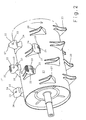
- Figur 2:
- eine Zuführtrommel mit unterschiedlichen erfindungsgemäßen Mitnehmern
- FIG. 1:
- a schematic cross section through an executed as a combine agricultural machine and their working aggregates
- FIG. 2:
- a feed drum with different drivers according to the invention
In der Figur 1 ist eine als selbstfahrender Mähdrescher 1 ausgeführte landwirtschaftliche Arbeitsmaschine 2 in schematischer Querschnittdarstellung abgebildet. In dem frontseitigen Bereich des Mähdreschers 1 ist ein Schneidwerk 3 angeordnet, welches das Erntegut 4 aufnimmt, schneidet und es mittels eines Förderorgans 5 an den nachgeordneten Schrägförderer 6 übergibt. Am Ende des Schrägförderers sind unterschiedliche Arbeitsaggregate 7, 8, 9 angeordnet, die das Erntegut 4, beispielsweise Weizen, annehmen. Die unterschiedlichen Förder- und Arbeitsaggregate 7, 8, 9 haben die Aufgabe das Erntegut 4 aufzubereiten und an weitere Maschinenaggregate zu übergeben. Hierbei beschleunigt die vorliegend im Tangentialfluss arbeitende und gegen den Uhrzeigersinn rotierende Zuführtrommel 7 die Erntegutmatte und übernimmt neben der Förderfunktion gleichzeitig eine Dreschfunktion. Ferner schlägt die Zuführtrommel 7 die Erntegutmatte auseinander und erzeugt, für eine verbesserte Abscheidung, eine dünnere und gleichmäßigere Erntegutmatte. Die besondere Ausgestaltung der Zuführtrommel 7 wird anhand der Figur 2 nachfolgend noch detaillierter beschrieben.
Der Zuführtrommel 7 ist eine Dreschtrommel 8 nachgeordnet. Die Dreschtrommel 8 beaufschlagt das Erntegut 4 und drischt die Körner 10 aus dem Erntegut 4, so dass das Erntegut 4 in ein Korn-Spreu-Gemisch und ein aus ausgedroschenen Halmen bestehenden Gutstrom geteilt wird. Die ausgedroschenen Körner 10 werden durch den unterhalb der Dreschtrommel 8 angeordneten Dreschkorb 9 in an sich bekannter Weise über einen Vorbereitungsboden 11 zu einer Reinigungseinrichtung 12 gefördert, die die Körner 10 von den restlichen Nichtkornbestandteilen trennt. Hinter der gegen den Uhrzeigersinn rotierenden Dreschtrommel 8 ist eine gegen den Uhrzeigersinn rotierende Wendetrommel 13 angeordnet, die den aus ausgedroschenen Halmen bestehenden Gutstrom auf eine als Hordenschüttler 14 ausgeführte Nachabscheideeinrichtung fördert. Der sich oszillierend bewegende Hordenschüttler 14 trennt dabei die restlichen im Gutstrom vorhandenen Körner 10 die über einen Rücklaufboden 15 ebenfalls in die Reinigungseinrichtung 12 gelangen, bevor das gereinigte Korn 10 in den Korntank 16 des Mähdreschers 1 gelangt. Durch die oszillierende Bewegung des Hordenschüttlers 14 wird das Stroh zudem aus dem rückwärtigen Bereich des Mähdreschers 1 gefördert und auf dem Feldboden abgelegt.FIG. 1 shows an agricultural working machine 2 designed as a self-propelled combine harvester 1 in a schematic cross-sectional representation. In the front area of the combine 1, a
The
In Figur 2 ist die Zuführtrommel 7 mit erfindungsgemäßen Mitnehmern 20 abgebildet.
Vorliegend weist die Zuführtrommel 7 einen geschlossenen Trommelmantel 21 auf. Die Mitnehmer 20 sind ortsfest mit dem Trommelmantel 21 verbunden. Es liegt im Rahmen der Erfindung beliebig viele Mitnehmer 20 in einer symmetrischen oder asymmetrischen Anordnung auf dem Trommelmantel 21 anzuordnen. Erfindungsgemäß laufen die in Drehrichtung der Zuführtrommel 7 angeschrägten Wirkflächen der Mitnehmer 20 zu ihrem Ende hin spitz zu, so dass die Wirkflächen der Mitnehmer 20 insgesamt keilformartig ausgebildet sind.
Aufgrund dieser keilformartigen Ausbildung haben die Mitnehmer 20 eine kleine Wirkfläche mit der das Erntegut 4 beaufschlagt wird. Insbesondere eignet sich der Einsatz der Mitnehmer 20 mit keilförmiger Wirkfläche bei gerade gereiftem Erntegut 4, da dieses Erntegut 4 besonders empfindlich ist und bei einer zu starken Beaufschlagung, wie beispielsweise durch breit ausgeführte Mitnehmerwirkflächen oder durch allgemein bekannte und hier nicht abgebildete Dreschleisten, zu stark belastet wird. Durch den Einsatz von Mitnehmern 20 mit keilförmiger Wirkfläche wird demgemäss das Erntegut 4 verbessert angenommen und beschleunigt, da die Mitnehmer 20 mit keilförmiger Wirkfläche greifend und nicht reibend das Erntegut 4 annehmen und an die dahinterliegende Dreschtrommel 8 übergeben. Durch die kleinere Wirkfläche und die sanfte Förderung des Ernteguts wird weniger Bruchkorn und Kurzstroh produziert und ein Abschlagen von ganzen Ähren wird vermieden. Insbesondere abgerissene Ähren bewirken eine schlechte Kornsauberkeit, da sie oftmals direkt in den Korntank 16 wandern. Für den Fall, dass die Ähren als Überkehr erneut der Dreschtrommel 8 zugeführt werden, wird darüber hinaus der Dreschprozess unnötig belastet.FIG. 2 shows the
In the present case, the
Because of this wedge-shaped design, the
Es liegt im Rahmen der Erfindung die Mitnehmer 20 austauschbar auf der Zuführtrommel 7 anzuordnen. Durch die Austauschbarkeit der Mitnehmer 20 können insbesondere verschlissene Mitnehmer 20 mühelos ersetzt oder auch den Erntebedingungen angepasst werden.It is within the scope of the invention to arrange the
Eine besonders schonende Annahme und Förderung des Ernteguts 4 wird durch die nachgebende Ausführung der Mitnehmer 20 erreicht. Diese nachgebende Ausführung kann beispielsweise durch weiche Gummimitnehmer erreicht werden. Vorstellbar wären jedoch auch Mitnehmer 20, die bei einer starken Druckbeaufschlagung in den Trommelmantel 21 hineinwandern und bei nachlassender Druckbeaufschlagung wieder in ihre Ausgangsstellung zurück kehren. Fertigungstechnisch ist aber auch jede andere Art von Material zur Herstellung der Mitnehmer 20 vorstellbar.A particularly gentle acceptance and promotion of the
Wie sich aus Figur 2 ergibt können den Mitnehmern 20 Kappen 22 zugeordnet werden.
Die Kappen 22 können durch allgemein bekannte Befestigungselemente 23 mit den Mitnehmer 20 verbunden und gelöst werden. Hierdurch sind die Kappen 22 beliebig oft und einfach austauschbar.
Aufgabe der Kappen 22 ist, die Mitnehmer 20 vor Verschleiß zu schützen sowie unterschiedliches Erntegut 4 optimal zu fördern und zu bearbeiten. Darüber hinaus ist bei jeder Emtefahrt der unterschiedliche Reifegrad des Ernteguts 4 zu beachten, der einen unterschiedlichen Drusch erforderlich macht. Aus diesem Grund können unterschiedliche geometrische Formen von Kappen 22 verwendet werden. Beispielsweise können Kappen 22 mit einer geraden, spitzen, mehreckigen und/oder profilierten geometrischen Wirkfläche 24 verwendet werden. Die Verwendung von geraden Wirkflächen 24 ist vor allem unter trockenen Erntebedingungen sinnvoll, da trockenes Erntegut 4 zur besseren Bearbeitung eine höhere Reibung erfordert. Die geraden Wirkflächen 24 können außerdem als profilierte Wirkflächen 25 ausgeführt werden. Die Profilierung der Wirkflächen 25 verbessert zusätzlich den Dresch- und Reinigungseffekt.As can be seen from FIG. 2, caps 20 can be assigned to the
The
The task of the
Durch die Verstellbarkeit der Kappen 22 können die Kappen 22 auf einfache Weise verdreht werden, so dass jederzeit unterschiedliche geometrische Wirkflächen zum Einsatz gebracht werden können. Durch die Verdrehbarkeit der Kappen 22 kann die Kappe 20 länger benutzt werden, da die verschlissene Wirkflächen 25 verdreht und gegen die gegenüberliegende unbenutzte Wirkfläche 24 ausgetauscht werden kann.Due to the adjustability of the
Eine weitere geometrische Ausführungsform der Kappen 22 ist eine dreieckige Ausführungsform, die sich in etwa der keilartige Form der Mitnehmer 20 anpasst. Durch die Dreiecksform der Kappe 26 können spitze Wirkflächen 27 - und durch die Verdrehbarkeit der Kappe 26 - gerade Wirkflächen 24 zum Einsatz gebracht werden. Auf diese Weise können die zuvor beschriebenen Vorteile einer spitzen Wirkfläche 27 und einer geraden Wirkfläche 24 erreicht werden.
Alternativ kann die gerade Wirkfläche 28 auch als profilierte Wirkfläche 29 ausgeführt sein und zur Bearbeitung des Ernteguts 4 in Arbeitsstellung verstellt werden.Another geometric embodiment of the
Alternatively, the straight active surface 28 can also be embodied as a profiled
Auf fertigungstechnisch einfache Weise können die Kappen 22 aus unterschiedlichen Materialien ausgeführt sein. Insbesondere hat sich eine Kappe 22 aus weichem Gummi in der Praxis bewährt. Durch die weiche Gummikappe geben die Kappen 22 bei der Beaufschlagung des Ernteguts 4 nach. Die nachgebende Kappe 22 bietet den Vorteil einer sehr schonenden Bearbeitung des Ernteguts 4, so dass wenig Bruchkom oder beschädigtes Stroh produziert wird.In manufacturing technology simple way, the
Es liegt im Rahmen des Könnens eines Fachmanns das beschriebene Ausführungsbeispiel in nicht dargestellter Weise abzuwandeln oder in anderen Maschinen einzusetzen, um die beschriebenen Effekte zu erzielen, ohne dabei den Rahmen der Erfindung zu verlassen.It is within the skill of one skilled in the art to modify the described embodiment in a manner not shown or to use in other machines to achieve the effects described, without departing from the scope of the invention.
- 11
- Selbstfahrender MähdrescherSelf-propelled combine harvester
- 22
- landwirtschaftliche Arbeitsmaschineagricultural working machine
- 33
- Schneidwerkcutting
- 44
- Erntegutcrop
- 55
- Förderorganconveying member
- 66
- Schrägfördererfeederhouse
- 77
- Zuführtrommelfeed drum
- 88th
- Dreschtrommelthreshing
- 99
- Dreschkorbconcave
- 1010
- Körnergrains
- 1111
- Vorbereitungsbodenpreparing the ground
- 1212
- Reinigungseinrichtungcleaning device
- 1313
- Wendetrommelbeater
- 1414
- HordenschüttlerA straw walker
- 1515
- RücklaufbodenReturn pan
- 1616
- Korntankgrain tank
- 2020
- Mitnehmertakeaway
- 2121
- Trommelmanteldrum shell
- 2222
- Kappencut
- 2323
- Befestigungselementefasteners
- 2424
- gerade Wirkflächestraight effective area
- 2525
- profilierte gerade Wirkflächeprofiled straight active surface
- 2626
- Kappecap
- 2727
- spitze Wirkflächepeak effective area
- 2929
- profilierte gerade Wirkflächeprofiled straight active surface
Claims (10)
dadurch gekennzeichnet, dass
die Wirkfläche der Mitnehmer (20) keilförmig und angeschrägt ausgebildet sind.A feed drum equipped with drivers in a self-propelled combine harvester,
characterized in that
the active surface of the driver (20) are wedge-shaped and bevelled.
dadurch gekennzeichnet, dass
die Wirkflächen der Mitnehmer (20) entgegen der Drehrichtung der Zuführtrommel (7) angeschrägt sind.A feed drum equipped with drivers according to claim 1,
characterized in that
the active surfaces of the driver (20) against the direction of rotation of the feed drum (7) are bevelled.
dadurch gekennzeichnet, dass
die Mitnehmer (20) austauschbar auf dem Zuführtrommel (7) angeordnet sind.A feed drum equipped with drivers according to one or more of the preceding claims,
characterized in that
the drivers (20) are arranged interchangeably on the feed drum (7).
dadurch gekennzeichnet, dass
die Mitnehmer (20) nachgebend ausgeführt sind.A feed drum equipped with drivers according to one or more of the preceding claims,
characterized in that
the drivers (20) are compliant.
dadurch gekennzeichnet, dass
den Mitnehmern (20) Kappen (22) zugeordnet sind.A feed drum equipped with drivers according to one or more of the preceding claims,
characterized in that
the drivers (20) caps (22) are assigned.
dadurch gekennzeichnet, dass
die den Mitnehmern (20) zugeordneten Kappen (22) austauschbar sind.A feed drum equipped with drivers according to one or more of the preceding claims,
characterized in that
the caps (22) associated with the drivers (20) are exchangeable.
dadurch gekennzeichnet, dass
die Kappen (22) unterschiedlich geformte geometrische Wirkflächen (24, 25, 27, 28, 29) aufweisen.A feed drum equipped with drivers according to one or more of the preceding claims,
characterized in that
the caps (22) have differently shaped geometric active surfaces (24, 25, 27, 28, 29).
dadurch gekennzeichnet, dass
die geometrischen Wirkflächen (24, 25, 27, 28, 29) der Kappen (22) spitz, gerade, mehreckig und/oder profiliert sind.A feed drum equipped with drivers according to claim 7,
characterized in that
the geometric active surfaces (24, 25, 27, 28, 29) of the caps (22) are pointed, straight, polygonal and / or profiled.
dadurch gekennzeichnet, dass
die Kappen (22) verstellbar sind.A feed drum equipped with drivers according to one or more of the preceding claims,
characterized in that
the caps (22) are adjustable.
dadurch gekennzeichnet, dass
die Kappen (22) nachgebend ausgeführt sind.A feed drum equipped with drivers according to one or more of the preceding claims,
characterized in that
the caps (22) are made yielding.
Applications Claiming Priority (1)
| Application Number | Priority Date | Filing Date | Title |
|---|---|---|---|
| DE102004048084A DE102004048084A1 (en) | 2004-09-30 | 2004-09-30 | Carrier on a feed drum of a self-propelled combine harvester |
Publications (2)
| Publication Number | Publication Date |
|---|---|
| EP1642489A1 true EP1642489A1 (en) | 2006-04-05 |
| EP1642489B1 EP1642489B1 (en) | 2008-02-13 |
Family
ID=35539733
Family Applications (1)
| Application Number | Title | Priority Date | Filing Date |
|---|---|---|---|
| EP05017088A Active EP1642489B1 (en) | 2004-09-30 | 2005-08-05 | Feeding element at a feeding drum of a self-propelled combine harvester |
Country Status (5)
| Country | Link |
|---|---|
| US (1) | US7201652B2 (en) |
| EP (1) | EP1642489B1 (en) |
| AT (1) | ATE385679T1 (en) |
| DE (2) | DE102004048084A1 (en) |
| RU (1) | RU2373686C2 (en) |
Families Citing this family (11)
| Publication number | Priority date | Publication date | Assignee | Title |
|---|---|---|---|---|
| US20070026913A1 (en) * | 2005-07-27 | 2007-02-01 | Kuchar George J | Crop processing element for a rotary combine |
| US7771261B2 (en) * | 2008-08-12 | 2010-08-10 | Deere & Company | Knife blade for a chopper of a combine harvester |
| DE102009055965B4 (en) * | 2009-11-27 | 2019-11-07 | Claas Selbstfahrende Erntemaschinen Gmbh | Gutförderrotor for a combine harvester |
| DE102011000426A1 (en) | 2011-02-01 | 2012-08-02 | Claas Selbstfahrende Erntemaschinen Gmbh | Dreschwerk of a combine harvester |
| US8087982B1 (en) | 2011-07-09 | 2012-01-03 | Kile Ronald J | Threshing bars and combine harvester thresher formed therewith |
| US8529325B2 (en) * | 2011-07-09 | 2013-09-10 | Ronald J. Kile | Threshing bars with cutting blades and combine harvester thresher formed therewith |
| US9456548B2 (en) * | 2014-02-14 | 2016-10-04 | Deere & Company | Conveyer for a material processing machine |
| JP6342341B2 (en) * | 2014-09-11 | 2018-06-13 | 株式会社クボタ | Combine |
| US10159192B2 (en) | 2015-09-17 | 2018-12-25 | Cone Guard, Llc | Transition cone liner for a farm combine |
| RU2749739C1 (en) * | 2020-07-23 | 2021-06-16 | Федеральное государственное бюджетное образовательное учреждение высшего образования "Брянский государственный аграрный университет" | Feed reel of threshing device of combine harvester |
| DE102020130846A1 (en) | 2020-11-23 | 2022-05-25 | Claas Selbstfahrende Erntemaschinen Gmbh | Agricultural working machine with a drum |
Citations (6)
| Publication number | Priority date | Publication date | Assignee | Title |
|---|---|---|---|---|
| DE10705C (en) * | 1879-07-12 | 1880-09-01 | H. HANAUER in Winnweiler i. d. Rheinpfalz | Threshing drum with flexible threshing pins |
| US2463061A (en) * | 1947-05-12 | 1949-03-01 | W J Small Company Inc | Alfalfa harvester |
| GB1149188A (en) * | 1965-10-16 | 1969-04-16 | Bautz Gmbh Josef | Feeder drum for harvesters |
| US4487005A (en) * | 1981-08-05 | 1984-12-11 | Claas Ohg. | Drawing roller with controlled drawing fingers for agricultural machine |
| DE3827256C1 (en) * | 1988-08-11 | 1989-06-29 | Deere & Co., Moline, Ill., Us, Niederlassung Deere & Co. European Office, 6800 Mannheim, De | Feed drum for a cutting-off unit |
| EP0836800A1 (en) * | 1996-10-04 | 1998-04-22 | Sampo Rosenlew Oy | Combine harvester |
Family Cites Families (10)
| Publication number | Priority date | Publication date | Assignee | Title |
|---|---|---|---|---|
| US3209760A (en) * | 1960-10-25 | 1965-10-05 | Claas Reinhold | Concave extension and rock trap for a thresher |
| US3494115A (en) * | 1966-09-01 | 1970-02-10 | Massey Ferguson Ind Ltd | Vibrational grain separating apparatus for agricultural combines |
| US3662763A (en) * | 1970-07-22 | 1972-05-16 | Deere & Co | Combine |
| US4108150A (en) * | 1977-03-23 | 1978-08-22 | Allis-Chalmers Corporation | Agitator for an axial flow cylinder |
| US4154250A (en) * | 1978-03-03 | 1979-05-15 | Allis-Chalmers Corporation | Drive mechanism and support arrangement for agitator of axial flow threshing cylinder |
| DE3363911D1 (en) * | 1982-06-19 | 1986-07-10 | Sperry Nv | Combine harvesters |
| US5192245A (en) * | 1991-09-09 | 1993-03-09 | Case Corporation | Thresher elements for a combine |
| US5192246A (en) * | 1991-11-15 | 1993-03-09 | Case Corporation | Rotor assembly for a combine |
| US6264553B1 (en) * | 1999-08-16 | 2001-07-24 | Case Corporation | Rasp bar threshing element and assembly |
| US6325714B1 (en) * | 1999-10-07 | 2001-12-04 | Case Corporation | Rotor assembly for a combine |
-
2004
- 2004-09-30 DE DE102004048084A patent/DE102004048084A1/en not_active Withdrawn
-
2005
- 2005-08-05 AT AT05017088T patent/ATE385679T1/en not_active IP Right Cessation
- 2005-08-05 EP EP05017088A patent/EP1642489B1/en active Active
- 2005-08-05 DE DE502005002809T patent/DE502005002809D1/en active Active
- 2005-09-26 RU RU2005129599/12A patent/RU2373686C2/en active
- 2005-09-27 US US11/236,781 patent/US7201652B2/en not_active Expired - Fee Related
Patent Citations (6)
| Publication number | Priority date | Publication date | Assignee | Title |
|---|---|---|---|---|
| DE10705C (en) * | 1879-07-12 | 1880-09-01 | H. HANAUER in Winnweiler i. d. Rheinpfalz | Threshing drum with flexible threshing pins |
| US2463061A (en) * | 1947-05-12 | 1949-03-01 | W J Small Company Inc | Alfalfa harvester |
| GB1149188A (en) * | 1965-10-16 | 1969-04-16 | Bautz Gmbh Josef | Feeder drum for harvesters |
| US4487005A (en) * | 1981-08-05 | 1984-12-11 | Claas Ohg. | Drawing roller with controlled drawing fingers for agricultural machine |
| DE3827256C1 (en) * | 1988-08-11 | 1989-06-29 | Deere & Co., Moline, Ill., Us, Niederlassung Deere & Co. European Office, 6800 Mannheim, De | Feed drum for a cutting-off unit |
| EP0836800A1 (en) * | 1996-10-04 | 1998-04-22 | Sampo Rosenlew Oy | Combine harvester |
Also Published As
| Publication number | Publication date |
|---|---|
| US7201652B2 (en) | 2007-04-10 |
| US20060079307A1 (en) | 2006-04-13 |
| DE102004048084A1 (en) | 2006-04-13 |
| RU2373686C2 (en) | 2009-11-27 |
| ATE385679T1 (en) | 2008-03-15 |
| RU2005129599A (en) | 2007-04-10 |
| DE502005002809D1 (en) | 2008-03-27 |
| EP1642489B1 (en) | 2008-02-13 |
Similar Documents
| Publication | Publication Date | Title |
|---|---|---|
| EP1642489B1 (en) | Feeding element at a feeding drum of a self-propelled combine harvester | |
| EP1671532B1 (en) | Forage chopping cylinder | |
| EP2842412A1 (en) | Crop processing and/or conveying element for a forage harvester | |
| DE102013226436B4 (en) | Feederhouse for a combine harvester | |
| EP1797753B1 (en) | Forage harvester | |
| DE202006011777U1 (en) | Thrashing tongs for a combine harvester comprises a groove which runs diagonally over the front surface of the material interacting sections | |
| EP1226747B1 (en) | Drum with interchangeable feeding elements | |
| EP2058095B1 (en) | Chipping machine | |
| EP1040746B1 (en) | Device for harvesting fruit on stalks | |
| EP3654754A1 (en) | Device for separating grain from harvested ears, in particular a slope conveyor | |
| EP3354126B1 (en) | Cutter and shredding drum for a chaff cutter | |
| DD255663A5 (en) | ERNTEGERAET | |
| EP2774474B1 (en) | Combine harvester | |
| DE102007043667A1 (en) | Concave arrangement for a combine harvester | |
| DE1965025B1 (en) | Arrangement for re-threshing the goods which have not been threshed through the cleaning device of a threshing machine or a combine harvester | |
| EP1000533B1 (en) | Picking device for harvesting cereals | |
| EP3782454A1 (en) | Feeding drum | |
| EP2563518B1 (en) | Comb tooth holder | |
| EP1961289A1 (en) | Agricultural working machine | |
| EP2106685B1 (en) | Forage harvester with conditioning device | |
| DE1191160B (en) | Threshing machine, in particular a combine harvester | |
| EP2823702A1 (en) | Fine crushing device | |
| DE102015006017A1 (en) | Cutting unit for agricultural harvesters | |
| DE102012112265A1 (en) | post-chopper reduction | |
| EP2347645A1 (en) | Distributor device for a self-propelled harvesting machine |
Legal Events
| Date | Code | Title | Description |
|---|---|---|---|
| PUAI | Public reference made under article 153(3) epc to a published international application that has entered the european phase |
Free format text: ORIGINAL CODE: 0009012 |
|
| AK | Designated contracting states |
Kind code of ref document: A1 Designated state(s): AT BE BG CH CY CZ DE DK EE ES FI FR GB GR HU IE IS IT LI LT LU LV MC NL PL PT RO SE SI SK TR |
|
| AX | Request for extension of the european patent |
Extension state: AL BA HR MK YU |
|
| 17P | Request for examination filed |
Effective date: 20061005 |
|
| 17Q | First examination report despatched |
Effective date: 20061107 |
|
| AKX | Designation fees paid |
Designated state(s): AT BE BG CH CY CZ DE DK EE ES FI FR GB GR HU IE IS IT LI LT LU LV MC NL PL PT RO SE SI SK TR |
|
| 17Q | First examination report despatched |
Effective date: 20061107 |
|
| GRAP | Despatch of communication of intention to grant a patent |
Free format text: ORIGINAL CODE: EPIDOSNIGR1 |
|
| GRAS | Grant fee paid |
Free format text: ORIGINAL CODE: EPIDOSNIGR3 |
|
| GRAA | (expected) grant |
Free format text: ORIGINAL CODE: 0009210 |
|
| AK | Designated contracting states |
Kind code of ref document: B1 Designated state(s): AT BE BG CH CY CZ DE DK EE ES FI FR GB GR HU IE IS IT LI LT LU LV MC NL PL PT RO SE SI SK TR |
|
| REG | Reference to a national code |
Ref country code: GB Ref legal event code: FG4D Free format text: NOT ENGLISH |
|
| REG | Reference to a national code |
Ref country code: CH Ref legal event code: EP |
|
| REG | Reference to a national code |
Ref country code: IE Ref legal event code: FG4D Free format text: LANGUAGE OF EP DOCUMENT: GERMAN |
|
| REF | Corresponds to: |
Ref document number: 502005002809 Country of ref document: DE Date of ref document: 20080327 Kind code of ref document: P |
|
| PG25 | Lapsed in a contracting state [announced via postgrant information from national office to epo] |
Ref country code: FI Free format text: LAPSE BECAUSE OF FAILURE TO SUBMIT A TRANSLATION OF THE DESCRIPTION OR TO PAY THE FEE WITHIN THE PRESCRIBED TIME-LIMIT Effective date: 20080213 Ref country code: ES Free format text: LAPSE BECAUSE OF FAILURE TO SUBMIT A TRANSLATION OF THE DESCRIPTION OR TO PAY THE FEE WITHIN THE PRESCRIBED TIME-LIMIT Effective date: 20080524 Ref country code: IS Free format text: LAPSE BECAUSE OF FAILURE TO SUBMIT A TRANSLATION OF THE DESCRIPTION OR TO PAY THE FEE WITHIN THE PRESCRIBED TIME-LIMIT Effective date: 20080613 |
|
| NLV1 | Nl: lapsed or annulled due to failure to fulfill the requirements of art. 29p and 29m of the patents act | ||
| PG25 | Lapsed in a contracting state [announced via postgrant information from national office to epo] |
Ref country code: SI Free format text: LAPSE BECAUSE OF FAILURE TO SUBMIT A TRANSLATION OF THE DESCRIPTION OR TO PAY THE FEE WITHIN THE PRESCRIBED TIME-LIMIT Effective date: 20080213 Ref country code: LV Free format text: LAPSE BECAUSE OF FAILURE TO SUBMIT A TRANSLATION OF THE DESCRIPTION OR TO PAY THE FEE WITHIN THE PRESCRIBED TIME-LIMIT Effective date: 20080213 Ref country code: PL Free format text: LAPSE BECAUSE OF FAILURE TO SUBMIT A TRANSLATION OF THE DESCRIPTION OR TO PAY THE FEE WITHIN THE PRESCRIBED TIME-LIMIT Effective date: 20080213 |
|
| REG | Reference to a national code |
Ref country code: IE Ref legal event code: FD4D |
|
| PG25 | Lapsed in a contracting state [announced via postgrant information from national office to epo] |
Ref country code: SK Free format text: LAPSE BECAUSE OF FAILURE TO SUBMIT A TRANSLATION OF THE DESCRIPTION OR TO PAY THE FEE WITHIN THE PRESCRIBED TIME-LIMIT Effective date: 20080213 Ref country code: NL Free format text: LAPSE BECAUSE OF FAILURE TO SUBMIT A TRANSLATION OF THE DESCRIPTION OR TO PAY THE FEE WITHIN THE PRESCRIBED TIME-LIMIT Effective date: 20080213 Ref country code: SE Free format text: LAPSE BECAUSE OF FAILURE TO SUBMIT A TRANSLATION OF THE DESCRIPTION OR TO PAY THE FEE WITHIN THE PRESCRIBED TIME-LIMIT Effective date: 20080513 Ref country code: PT Free format text: LAPSE BECAUSE OF FAILURE TO SUBMIT A TRANSLATION OF THE DESCRIPTION OR TO PAY THE FEE WITHIN THE PRESCRIBED TIME-LIMIT Effective date: 20080714 Ref country code: CZ Free format text: LAPSE BECAUSE OF FAILURE TO SUBMIT A TRANSLATION OF THE DESCRIPTION OR TO PAY THE FEE WITHIN THE PRESCRIBED TIME-LIMIT Effective date: 20080213 Ref country code: IE Free format text: LAPSE BECAUSE OF FAILURE TO SUBMIT A TRANSLATION OF THE DESCRIPTION OR TO PAY THE FEE WITHIN THE PRESCRIBED TIME-LIMIT Effective date: 20080213 Ref country code: DK Free format text: LAPSE BECAUSE OF FAILURE TO SUBMIT A TRANSLATION OF THE DESCRIPTION OR TO PAY THE FEE WITHIN THE PRESCRIBED TIME-LIMIT Effective date: 20080213 |
|
| PG25 | Lapsed in a contracting state [announced via postgrant information from national office to epo] |
Ref country code: RO Free format text: LAPSE BECAUSE OF FAILURE TO SUBMIT A TRANSLATION OF THE DESCRIPTION OR TO PAY THE FEE WITHIN THE PRESCRIBED TIME-LIMIT Effective date: 20080213 |
|
| EN | Fr: translation not filed | ||
| PLBE | No opposition filed within time limit |
Free format text: ORIGINAL CODE: 0009261 |
|
| STAA | Information on the status of an ep patent application or granted ep patent |
Free format text: STATUS: NO OPPOSITION FILED WITHIN TIME LIMIT |
|
| 26N | No opposition filed |
Effective date: 20081114 |
|
| PG25 | Lapsed in a contracting state [announced via postgrant information from national office to epo] |
Ref country code: LT Free format text: LAPSE BECAUSE OF FAILURE TO SUBMIT A TRANSLATION OF THE DESCRIPTION OR TO PAY THE FEE WITHIN THE PRESCRIBED TIME-LIMIT Effective date: 20080213 |
|
| PG25 | Lapsed in a contracting state [announced via postgrant information from national office to epo] |
Ref country code: MC Free format text: LAPSE BECAUSE OF NON-PAYMENT OF DUE FEES Effective date: 20080831 |
|
| PG25 | Lapsed in a contracting state [announced via postgrant information from national office to epo] |
Ref country code: EE Free format text: LAPSE BECAUSE OF FAILURE TO SUBMIT A TRANSLATION OF THE DESCRIPTION OR TO PAY THE FEE WITHIN THE PRESCRIBED TIME-LIMIT Effective date: 20080213 Ref country code: FR Free format text: LAPSE BECAUSE OF FAILURE TO SUBMIT A TRANSLATION OF THE DESCRIPTION OR TO PAY THE FEE WITHIN THE PRESCRIBED TIME-LIMIT Effective date: 20081205 Ref country code: BG Free format text: LAPSE BECAUSE OF FAILURE TO SUBMIT A TRANSLATION OF THE DESCRIPTION OR TO PAY THE FEE WITHIN THE PRESCRIBED TIME-LIMIT Effective date: 20080513 |
|
| PG25 | Lapsed in a contracting state [announced via postgrant information from national office to epo] |
Ref country code: BE Free format text: LAPSE BECAUSE OF NON-PAYMENT OF DUE FEES Effective date: 20080831 Ref country code: CY Free format text: LAPSE BECAUSE OF FAILURE TO SUBMIT A TRANSLATION OF THE DESCRIPTION OR TO PAY THE FEE WITHIN THE PRESCRIBED TIME-LIMIT Effective date: 20080213 |
|
| PG25 | Lapsed in a contracting state [announced via postgrant information from national office to epo] |
Ref country code: IT Free format text: LAPSE BECAUSE OF FAILURE TO SUBMIT A TRANSLATION OF THE DESCRIPTION OR TO PAY THE FEE WITHIN THE PRESCRIBED TIME-LIMIT Effective date: 20080213 |
|
| PG25 | Lapsed in a contracting state [announced via postgrant information from national office to epo] |
Ref country code: AT Free format text: LAPSE BECAUSE OF NON-PAYMENT OF DUE FEES Effective date: 20080805 |
|
| REG | Reference to a national code |
Ref country code: CH Ref legal event code: PL |
|
| GBPC | Gb: european patent ceased through non-payment of renewal fee |
Effective date: 20090805 |
|
| PG25 | Lapsed in a contracting state [announced via postgrant information from national office to epo] |
Ref country code: LI Free format text: LAPSE BECAUSE OF NON-PAYMENT OF DUE FEES Effective date: 20090831 Ref country code: CH Free format text: LAPSE BECAUSE OF NON-PAYMENT OF DUE FEES Effective date: 20090831 |
|
| PG25 | Lapsed in a contracting state [announced via postgrant information from national office to epo] |
Ref country code: HU Free format text: LAPSE BECAUSE OF FAILURE TO SUBMIT A TRANSLATION OF THE DESCRIPTION OR TO PAY THE FEE WITHIN THE PRESCRIBED TIME-LIMIT Effective date: 20080814 Ref country code: LU Free format text: LAPSE BECAUSE OF NON-PAYMENT OF DUE FEES Effective date: 20080805 |
|
| PG25 | Lapsed in a contracting state [announced via postgrant information from national office to epo] |
Ref country code: TR Free format text: LAPSE BECAUSE OF FAILURE TO SUBMIT A TRANSLATION OF THE DESCRIPTION OR TO PAY THE FEE WITHIN THE PRESCRIBED TIME-LIMIT Effective date: 20080213 |
|
| PG25 | Lapsed in a contracting state [announced via postgrant information from national office to epo] |
Ref country code: GR Free format text: LAPSE BECAUSE OF FAILURE TO SUBMIT A TRANSLATION OF THE DESCRIPTION OR TO PAY THE FEE WITHIN THE PRESCRIBED TIME-LIMIT Effective date: 20080514 |
|
| PG25 | Lapsed in a contracting state [announced via postgrant information from national office to epo] |
Ref country code: GB Free format text: LAPSE BECAUSE OF NON-PAYMENT OF DUE FEES Effective date: 20090805 |
|
| REG | Reference to a national code |
Ref country code: DE Ref legal event code: R084 Ref document number: 502005002809 Country of ref document: DE |
|
| P01 | Opt-out of the competence of the unified patent court (upc) registered |
Effective date: 20230512 |
|
| PGFP | Annual fee paid to national office [announced via postgrant information from national office to epo] |
Ref country code: DE Payment date: 20230821 Year of fee payment: 19 |