EP1641316A2 - Device for fixing the control elements of hearing devices resp. hearing aids - Google Patents
Device for fixing the control elements of hearing devices resp. hearing aids Download PDFInfo
- Publication number
- EP1641316A2 EP1641316A2 EP05023790A EP05023790A EP1641316A2 EP 1641316 A2 EP1641316 A2 EP 1641316A2 EP 05023790 A EP05023790 A EP 05023790A EP 05023790 A EP05023790 A EP 05023790A EP 1641316 A2 EP1641316 A2 EP 1641316A2
- Authority
- EP
- European Patent Office
- Prior art keywords
- sleeve
- base plate
- resp
- hearing aid
- actuating element
- Prior art date
- Legal status (The legal status is an assumption and is not a legal conclusion. Google has not performed a legal analysis and makes no representation as to the accuracy of the status listed.)
- Granted
Links
Images


Classifications
-
- H—ELECTRICITY
- H04—ELECTRIC COMMUNICATION TECHNIQUE
- H04R—LOUDSPEAKERS, MICROPHONES, GRAMOPHONE PICK-UPS OR LIKE ACOUSTIC ELECTROMECHANICAL TRANSDUCERS; DEAF-AID SETS; PUBLIC ADDRESS SYSTEMS
- H04R25/00—Deaf-aid sets, i.e. electro-acoustic or electro-mechanical hearing aids; Electric tinnitus maskers providing an auditory perception
- H04R25/60—Mounting or interconnection of hearing aid parts, e.g. inside tips, housings or to ossicles
- H04R25/609—Mounting or interconnection of hearing aid parts, e.g. inside tips, housings or to ossicles of circuitry
-
- H—ELECTRICITY
- H01—ELECTRIC ELEMENTS
- H01H—ELECTRIC SWITCHES; RELAYS; SELECTORS; EMERGENCY PROTECTIVE DEVICES
- H01H2300/00—Orthogonal indexing scheme relating to electric switches, relays, selectors or emergency protective devices covered by H01H
- H01H2300/004—Application hearing aid
-
- H—ELECTRICITY
- H04—ELECTRIC COMMUNICATION TECHNIQUE
- H04R—LOUDSPEAKERS, MICROPHONES, GRAMOPHONE PICK-UPS OR LIKE ACOUSTIC ELECTROMECHANICAL TRANSDUCERS; DEAF-AID SETS; PUBLIC ADDRESS SYSTEMS
- H04R2225/00—Details of deaf aids covered by H04R25/00, not provided for in any of its subgroups
- H04R2225/025—In the ear hearing aids [ITE] hearing aids
-
- H—ELECTRICITY
- H04—ELECTRIC COMMUNICATION TECHNIQUE
- H04R—LOUDSPEAKERS, MICROPHONES, GRAMOPHONE PICK-UPS OR LIKE ACOUSTIC ELECTROMECHANICAL TRANSDUCERS; DEAF-AID SETS; PUBLIC ADDRESS SYSTEMS
- H04R2225/00—Details of deaf aids covered by H04R25/00, not provided for in any of its subgroups
- H04R2225/61—Aspects relating to mechanical or electronic switches or control elements, e.g. functioning
-
- H—ELECTRICITY
- H04—ELECTRIC COMMUNICATION TECHNIQUE
- H04R—LOUDSPEAKERS, MICROPHONES, GRAMOPHONE PICK-UPS OR LIKE ACOUSTIC ELECTROMECHANICAL TRANSDUCERS; DEAF-AID SETS; PUBLIC ADDRESS SYSTEMS
- H04R25/00—Deaf-aid sets, i.e. electro-acoustic or electro-mechanical hearing aids; Electric tinnitus maskers providing an auditory perception
- H04R25/60—Mounting or interconnection of hearing aid parts, e.g. inside tips, housings or to ossicles
- H04R25/603—Mounting or interconnection of hearing aid parts, e.g. inside tips, housings or to ossicles of mechanical or electronic switches or control elements
-
- H—ELECTRICITY
- H04—ELECTRIC COMMUNICATION TECHNIQUE
- H04R—LOUDSPEAKERS, MICROPHONES, GRAMOPHONE PICK-UPS OR LIKE ACOUSTIC ELECTROMECHANICAL TRANSDUCERS; DEAF-AID SETS; PUBLIC ADDRESS SYSTEMS
- H04R25/00—Deaf-aid sets, i.e. electro-acoustic or electro-mechanical hearing aids; Electric tinnitus maskers providing an auditory perception
- H04R25/65—Housing parts, e.g. shells, tips or moulds, or their manufacture
Landscapes
- Acoustics & Sound (AREA)
- Health & Medical Sciences (AREA)
- Neurosurgery (AREA)
- Otolaryngology (AREA)
- Physics & Mathematics (AREA)
- Engineering & Computer Science (AREA)
- General Health & Medical Sciences (AREA)
- Signal Processing (AREA)
- Auxiliary Devices For And Details Of Packaging Control (AREA)
- Switch Cases, Indication, And Locking (AREA)
- Connector Housings Or Holding Contact Members (AREA)
- Connection Of Plates (AREA)
- Insertion, Bundling And Securing Of Wires For Electric Apparatuses (AREA)
- Snaps, Bayonet Connections, Set Pins, And Snap Rings (AREA)
Abstract
Description
Die vorliegende Erfindung betrifft eine Befestigungsvorrichtung nach dem Oberbegriff von Anspruch 1, sowie ein Hörgerät nach dem Oberbegriff von Anspruch 9 und ein Verfahren nach dem Oberbegriff von Anspruch 10.The present invention relates to a fastening device according to the preamble of
Hörgeräte resp. Hörhilfen weisen in der Regel von Aussen bedienbare Betätigungselemente auf, wie beispielsweise Schalter, Drehregler und Taster. Diese Betätigungselemente müssen während des Betriebes bedient werden und sind daher beispielsweise bei Im-Ohr-Hörgeräten, d.h. während des Betriebes im Gehörgang eingesetzten Hörgeräten resp. Hörhilfen, an der Grundplatte resp. Faceplate angeordnet. Die Betätigungselemente müssen mit den elektrischen resp. elektronischen Komponenten des Hörgerätes resp. der Hörhilfe leitend verbunden werden, was in der Regel über Leitungen resp. Litzen erfolgt.Hearing aids resp. Hearing aids usually have externally operable actuators, such as switches, knobs and buttons. These actuators must be operated during operation and are therefore useful, for example, in in-the-ear hearing aids, i. during operation in the auditory canal used hearing aids resp. Hearing aids, on the base plate resp. Faceplate arranged. The actuators must comply with the electrical resp. electronic components of the hearing aid resp. the hearing aid are conductively connected, which is usually via lines respectively. Strands done.
Da die Grundplatten in der Regel für den jeweiligen Benutzer individualisiert hergestellt werden und die Rücklaufrate von derartigen Hörgeräten resp. Hörhilfen sehr gross ist, da in der ersten Trag- resp. Anpassungsphase häufig Probleme in Bezug auf Verträglichkeit und Tragkomfort auftreten, sollen möglichst viele Komponenten des Hörgerätes resp. Hörhilfe wieder verwendet werden können. Dies betrifft einerseits die elektronischen Komponenten, welche mit der Grundplatte elektrisch verbunden sind, und andererseits wenn möglich auch die Betätigungselemente.Since the base plates are usually made individualized for each user and the return rate of such hearing aids resp. Hearing aids is very large, since in the first Trag resp. Adaptation often problems in terms of compatibility and comfort occur, as many components of the hearing aid resp. Hearing aid can be used again. This applies on the one hand to the electronic components which are electrically connected to the base plate, and on the other hand, if possible, the actuators.
Die Betätigungselemente werden üblicherweise von Aussen in Ausnehmungen der Grundplatte eingesteckt und mittels Klebstoff mit der Grundplatte verbunden. Diese an sich sehr einfache Befestigung der Betätigungselemente weist allerdings den Nachteil auf, dass sie nachträglich praktisch kaum mehr zerstörungsfrei gelöst werden kann und damit die Betätigungselemente nicht mehr wieder verwendet werden können. Weiter muss vor der Weiterverarbeitung die Aushärtung des Klebestoffes abgewartet werden, da sich sonst das Betätigungselement aus seiner vorgesehenen Position verschieben oder lösen kann. Auch eine Verschmutzung des Betätigungselementes durch den Klebstoff ist nicht ausgeschlossen, was zu einer Beeinträchtigung der mechanischen und/oder der elektrischen Funktion führen kann.The actuators are usually inserted from the outside in recesses of the base plate and connected by adhesive to the base plate. However, this very simple attachment of the actuators has the disadvantage that they can be subsequently solved virtually no longer destructive and thus the actuators can not be used again. Next, the curing of the adhesive must be awaited before further processing, since otherwise the actuator can move or release from its intended position. A contamination of the actuating element by the adhesive is not excluded, which can lead to an impairment of the mechanical and / or electrical function.
Aus der US 4,835,833 ist eine alternative Lösung zur mechanischen Befestigung insbesondere von Potentiometern für Hörgeräte in der oben beschriebenen Anordnung bekannt. Dabei wird ein geschlossener Metallring um den Fussbereich des Gehäuses des Potentiometers aufgeschoben, welcher seinerseits zusammen mit dem Potentiometer in eine entsprechend dimensionierte Öffnung der Grundplatte eingeschoben wird. Am Metallring angeordnete umlaufende Rippen dienen dabei der Fixierung sowohl des Potentiometers wie auch des Metallringes in der Grundplatte. Damit wird eine stabile Verbindung zwischen Potentiometer und Grundplatte ohne Verwendung von Klebstoff erreicht. Allerdings lässt sich auch diese Verbindung wie die bereits erwähnte Verbindung mit Klebstoff nachträglich praktisch nicht mehr zerstörungsfrei lösen.From US 4,835,833 an alternative solution for mechanical fastening in particular of potentiometers for hearing aids in the arrangement described above is known. In this case, a closed metal ring is pushed around the foot of the housing of the potentiometer, which in turn is inserted together with the potentiometer in a correspondingly sized opening of the base plate. On the metal ring arranged circumferential ribs serve to fix both the potentiometer and the metal ring in the base plate. This achieves a stable connection between potentiometer and base plate without the use of glue. However, this compound, like the already mentioned compound with adhesive, can not be subsequently solved in a non-destructive way.
Ein weiterer Nachteil all dieser Lösungen liegt weiter darin, dass die Verbindungslitzen der Betätigungselemente mit den elektronischen Komponenten durch aufwändiges Ablöten entfernt werden müssen. Hierfür muss zuerst die Grundplatte von der Schale des Hörgerätes gelöst werden, da die Betätigungselemente nicht zerstörungsfrei von der Grundplatte gelöst werden können.Another disadvantage of all these solutions lies in the fact that the connecting wires of the actuators with the electronic components must be removed by consuming unsoldering. For this purpose, first the base plate must be detached from the shell of the hearing aid, since the actuators can not be solved destructively from the base plate.
Aus der US 5,157,371 ist nun eine Vorrichtung ebenfalls zur Befestigung eines Potentiometers mit der Grundplatte eines Hörgerätes bekannt, bei welchem das Potentiometer von Aussen in die Grundplatte eingesteckt und später ggf. wieder gelöst werden kann. Hierfür wird ein Adapter mit der Grundplatte verbunden, der elektrische Kontakte zur federnden Aufnahme von elektrischen Kontakten des Potentiometers aufweist. Nachteilig an dieser Konstruktion sind einerseits die Steckverbindung zur Erstellung der elektrischen Verbindung zu sehen, welche der Korrosion und Verschmutzung unterliegen und zu Fehlfunktionen führen können, und andererseits der aufwändige Aufbau des Adapters, der ebenfalls praktisch nicht oder nur mit hohem Aufwand von der Grundplatte zu entfernen ist.From US Pat. No. 5,157,371, a device is likewise known for fastening a potentiometer to the baseplate of a hearing aid, in which case the potentiometer can be inserted from the outside into the baseplate and later, if necessary, released again. For this purpose, an adapter is connected to the base plate having electrical contacts for resiliently receiving electrical contacts of the potentiometer. A disadvantage of this design, on the one hand to see the connector for creating the electrical connection, which are subject to corrosion and contamination and can lead to malfunction, and on the other hand, the complex structure of the adapter, which is also virtually impossible or only with great effort to remove from the base plate is.
Die Aufgabe der vorliegenden Erfindung bestand darin, eine Vorrichtung zur einfachen lösbaren Verbindung resp. Befestigung von Betätigungselementen an der Grundplatte von Hörgeräten resp. Hörhilfen zu finden, welche ein Trennen der Betätigungselemente von der Grundplatte ohne Lösen der Verbindung der elektrischen Verbindung der Betätigungselemente zu den elektronischen Komponenten des Hörgerätes resp. Hörhilfe erlaubt.The object of the present invention was to provide a device for easy detachable connection resp. Attachment of actuators on the base plate of hearing aids resp. To find hearing aids, which is a separation of the actuating elements of the base plate without releasing the connection of the electrical connection of the actuating elements to the electronic components of the hearing aid resp. Hearing aid allowed.
Diese Aufgabe wird erfindungsgemäss durch eine Vorrichtung mit den Merkmalen nach Anspruch 1 gelöst. Weitere, erfindungsgemässe Ausführungsformen ergeben sich aus den Merkmalen der weiteren Ansprüche 2 bis 8.This object is achieved according to the invention by a device having the features of
Erfindungsgemäss weist die Befestigungsvorrichtung zur Aufnahme und Verbindung von Betätigungselementen mit der Grundplatte resp. Faceplate von Hörgeräten resp. Hörhilfen, wobei die Betätigungselemente Anschlüsse für elektrische Verbindungen zu weiteren elektrischen resp. elektronischen Komponenten des Hörgerätes resp. Hörhilfen aufweisen, eine Hülse auf, die mit einem sich von einem zum anderen Ende der Hülse durchgehend erstreckenden Schlitz versehenen ist. Die Hülse lässt sich damit einerseits von Aussen auf einen Bereich des betreffenden Betätigungselementes aufschieben und andererseits in eine entsprechend dem Aussenmass der Hülse dimensionierte Ausnehmung der Grundplatte resp. Faceplate einschieben. Durch Klemmwirkung wird dabei sowohl die Befestigungsvorrichtung, d.h. die Hülse, wie auch das Betätigungselement in der Grundplatte geklemmt und in seiner Lage zuerlässig fixiert. Vorteilhaft lässt sich die Hülse resp. das Betätigungselement nachträglich wieder entfernen, indem es aus der Ausnehmung entgegen der Klemmwirkung herausgezogen wird.According to the invention, the fastening device for receiving and connecting actuators with the base plate resp. Faceplate of hearing aids resp. Hearing aids, wherein the actuators connections for electrical connections to further electrical resp. electronic components of the hearing aid resp. Hearing aids, a sleeve which is provided with a extending from one to the other end of the sleeve continuously extending slot. The sleeve can thus be pushed on the one hand from the outside to a region of the respective actuating element and on the other hand in a corresponding to the outer dimension of the sleeve sized recess of the base plate respectively. Insert faceplate. By clamping action, both the fastening device, i. the sleeve, as well as the actuator clamped in the base plate and fixed in position zuerlässig. Advantageously, the sleeve resp. Remove the actuator later again by being pulled out of the recess against the clamping action.
Beispielsweise weist die Hülse einen im Wesentlichen runden Querschnitt auf. Damit lässt sich die Hülse einfach herstellen und auch die Ausnehmung in der Grundplatte kann einfach durch eine Bohrung erstellt werden, resp. unter Einhaltung von engen Toleranzen einfach ausgeformt werden. In der Regel weisen auch die Betätigungselemente einen kreisrunden Querschnitt auf, wie insbesondere Potentiometer, welche für die manuelle Regelung beispielsweise der Lautstärke des Hörgerätes häufig eingesetzt werden.For example, the sleeve has a substantially round cross-section. Thus, the sleeve can be easily manufactured and also the recess in the base plate can be easily created by a hole, respectively. be easily formed while maintaining tight tolerances. As a rule, the actuators also have one circular cross section on, in particular potentiometers, which are often used for manual control, for example, the volume of the hearing aid.
Beispielweise sind an der Aussenseite der Hülse Vertiefungen oder Erhebungen ausgebildet, vorzugsweise als parallel zur Längsachse der Hülse verlaufende Rippen oder Nuten. Diese Rippen oder Nuten führen zu einer sehr stabilen Pressung zwischen Hülse und Grundplatte und damit letztlich zu einem sehr stabilen Presssitz der Hülse in der Grundplatte. Damit wird verhindert, dass sich die Hülse selbständig oder ungewollt aus seiner Position löst oder verschiebt. Weiter stellen diese Rippen oder Nuten auch eine Verdrehsicherung der Hülse dar, d.h. die Hülse lässt sich nach dem Einführen in die Grundplatte nicht mehr um ihre Achse verdrehen.For example, depressions or elevations are formed on the outside of the sleeve, preferably as ribs or grooves running parallel to the longitudinal axis of the sleeve. These ribs or grooves lead to a very stable pressure between the sleeve and the base plate and thus ultimately to a very stable interference fit of the sleeve in the base plate. This prevents the sleeve from being released or displaced automatically or unintentionally from its position. Further, these ribs or grooves also constitute an anti-rotation of the sleeve, i. the sleeve can not turn around its axis after insertion into the base plate.
Beispielsweise ist der Schlitz parallel zur Längsachse der Hülse verlaufend ausgebildet. Damit kann die Hülse sehr einfach hergestellt werden und weist eine gute Klemmwirkung auf. Selbstverständlich kann der Schlitz auch anders ausgestaltet werden, wie schraubenförmig schräg verlaufend oder mäanderförmig gerade oder schräg verlaufend. Damit wird einerseits die Länge des Schlitzes vergrössert und andererseits wird damit ein einfaches Eindringen von Fremdkörpern von Aussen in den Schlitz vermieden oder zumindest behindert.For example, the slot is designed to extend parallel to the longitudinal axis of the sleeve. Thus, the sleeve can be made very easily and has a good clamping action. Of course, the slot can also be configured differently, such as helically inclined or meandering straight or sloping. Thus, on the one hand, the length of the slot is increased and on the other hand, a simple penetration of foreign bodies from the outside is avoided in the slot or at least hindered.
Beispielsweise sind weiter an der Innenseite der Hülse Vertiefungen oder Erhebungen ausgebildet, vorzugsweise parallel zur Längsachse der Hülse verlaufende Rippen oder Nuten. Diese Rippen oder Nuten führen zu einer sehr stabilen Pressung zwischen Hülse und Betätigungselement und damit letztlich zu einer sehr stabilen Halterung des Betätigungselementes in der Grundplatte. Damit wird verhindert, dass sich das Betätigungselement selbständig oder ungewollt aus seiner Position löst oder verschiebt. Die Nuten oder Rippen können einen runden oder eckigen, vorzugsweise dreieckigen Querschnitt aufweisen. Denkbar ist auch die Anordnung mehrerer Rippen resp. Nuten nacheinander. Auch wird damit eine Verdrehsicherung des Betätigungselementes in der Hülse realisiert, was gerade bei als Drehschalter ausgebildeten Betätigungselementen wichtig ist.For example, further depressions or raised portions are formed on the inside of the sleeve, preferably ribs extending parallel to the longitudinal axis of the sleeve Grooves. These ribs or grooves lead to a very stable pressure between the sleeve and actuator and thus ultimately to a very stable mounting of the actuating element in the base plate. This prevents the actuating element from being released or displaced from its position independently or unintentionally. The grooves or ribs may have a round or angular, preferably triangular cross-section. It is also conceivable the arrangement of several ribs resp. Grooves one after another. Also, thus an anti-rotation of the actuating element is realized in the sleeve, which is important especially when trained as a rotary switch actuators.
Beispielsweise sind an einem Ende der Hülse radial nach Aussen gerichtete Rast- oder Anschlagelemente ausgebildet. Diese Elemente dienen einmal der genauen Positionierung der Hülse in der Grundplatte. So kann damit beispielsweise eine exakt definierte Einstecktiefe der Hülse festgelegt und eingehalten werden. Auch wird damit verhindert, dass die Hülse zu tief in die Grundplatte eingesteckt werden kann oder gar vollständig durch die Ausnehmung bis in das Innere des Hörgerätes resp. Hörhilfe eindringen kann.For example, radially outwardly directed latching or stop elements are formed at one end of the sleeve. These elements are once the exact positioning of the sleeve in the base plate. Thus, for example, a precisely defined insertion depth of the sleeve can be defined and adhered to. Also, this prevents that the sleeve can be inserted too deeply into the base plate or even completely through the recess into the interior of the hearing aid, respectively. Hearing aid can penetrate.
Beispielsweise ist der Aussendurchmesser der Hülse grösser als der grösste Durchmesser des darin einzuführenden Betätigungselementes. Diese Dimensionierung hat den Vorteil, dass das Betätigungselement ohne die Hülse von Aussen durch die Grundplatte hindurchgeführt werden kann. So kann beispielsweise das Betätigungselement mit einem oder mehreren Leitungen mit anderen elektronischen Komponenten, welche sich im Innern des Hörgerätes befinden, verbunden sein und ohne Unterbrechung dieser Verbindung von der Grundplatte gelöst werden. Dies ist besonders dann von grossem Vorteil, wenn die Leitungen durch Löten mit den elektronischen Komponenten resp. dem Betätigungselement verbunden sind, und damit ein Durchtrennen und nachträgliches Anlöten vermieden wird.For example, the outer diameter of the sleeve is greater than the largest diameter of the actuating element to be introduced therein. This dimensioning has the advantage that the actuating element can be passed without the sleeve from the outside through the base plate. For example, the actuator with one or more lines with other electronic Components which are located inside the hearing aid, be connected and be solved without interruption of this connection from the base plate. This is particularly of great advantage if the lines resp. By soldering to the electronic components. the actuating element are connected, and thus a cutting and subsequent soldering is avoided.
Beispielsweise besteht die Hülse aus einem mindestens teilelastischen Material, vorzugsweise aus Kunststoff. Damit die Hülse eine optimale Klemmwirkung entfalten kann, besteht sie vorteilhaft aus einem elastischen, aber formstabilen Material. Kunststoff eignet sich besonders gut dafür, da sich damit einerseits alle erforderlichen Formelemente einfach realisieren lassen und andererseits gerade grosse Stückzahlen kostengünstig und in hoher Präzision gefertigt werden können. Denkbar ist natürlich auch die Verwendung anderer Materialien, wie beispielsweise Metall.For example, the sleeve consists of an at least partially elastic material, preferably of plastic. So that the sleeve can develop an optimal clamping action, it advantageously consists of an elastic but dimensionally stable material. Plastic is particularly well suited for this because on the one hand all necessary form elements can be easily realized and on the other hand large quantities can be produced inexpensively and with high precision. Of course, it is also conceivable to use other materials, such as metal.
Die vorliegende Aufgabe wird erfindungsgemäss weiter durch ein Hörgerät resp. Hörhilfe mit Grundplatte und daran angeordneter Gehäuseschale, wobei die Grundplatte mindestens eine Ausnehmung zur Aufnahme eines Betätigungselementes aufweist, gelöst, bei welchem die Ausnehmung als durchgehende Ausnehmung zur Aufnahme einer Vorrichtung nach einem der Ansprüche 1 bis 8 ausgebildet ist.The present object is further according to the invention by a hearing aid resp. Hearing aid with base plate and disposed thereon housing shell, wherein the base plate has at least one recess for receiving an actuating element, solved, in which the recess is formed as a continuous recess for receiving a device according to one of
Die vorliegende Aufgabe wird weiter gelöst durch ein Verfahren zur Befestigung von Betätigungselementen mit der Grundplatte von Hörgeräten resp. Hörhilfen, wobei das Betätigungselement elektrisch mit den elektronischen Komponenten des Hörgerätes resp. der Hörhilfe verbunden wird, und danach das Betätigungselement von der Innenseite der Grundplatte her durch eine Ausnehmung in der Grundplatte zur Aussenseite der Grundplatte hindurchgeführt wird, und danach eine Vorrichtung nach einem der Ansprüche 1 bis 8 von Aussen in die Ausnehmung eingeführt wird und danach das Betätigungselement von Aussen in die Vorrichtung eingeschoben wird. Dadurch wird auch ein nachträgliches, zerstörungsfreies Entfernen des Betätigungselementes von der Grundplatte ermöglicht, ohne dass die elektrische Verbindung zwischen den elektronischen Komponenten des Hörgerätes resp. der Hörhilfe und des Betätigungselementes gelöst resp. getrennt werden muss.The present object is further achieved by a method for attachment of actuators with the base plate of hearing aids resp. Hearing aids, the Actuator electrically with the electronic components of the hearing aid resp. the hearing aid is connected, and thereafter the actuating element is passed from the inside of the base plate through a recess in the base plate to the outside of the base plate, and then a device according to any one of
Ausführungsbeispiele der vorliegenden Erfindung werden nachstehend anhand von Figuren noch näher erläutert. Es zeigen
- Fig. 1 die Ansicht eines in einer Grundplatte mittels einer erfindungsgemässen Vorrichtung eingesetzten Betätigungselementes in Form eines Drehschalters oder Potentiometers;
- Fig. 2 die Ansicht von der Innenseite der Grundplatte her auf die Unterseite des Betätigungselementes nach Figur 1;
- Fig. 3 die Ansicht des aus der Grundplatte zur Aussenseite hin entfernten Betätigungselementes
von Figur 1; - Fig. 4 die Ansicht des Betätigungselementes und der aus der Grundplatte gelösten Vorrichtung;
- Fig. 5 die
Ansicht nach Figur 4 mit vom Betätigungselement resp. dessen Verbindungsleitungen getrennter Vorrichtung; und - Fig. 6 die Ansicht des durch die Grundplatte nach Innen durchgeschobenen Betätigungselementes nach Figur 1.
- Figure 1 is a view of an operating element used in a base plate by means of a device according to the invention in the form of a rotary switch or potentiometer.
- 2 shows the view from the inside of the base plate forth on the underside of the actuating element of Figure 1;
- FIG. 3 shows the view of the actuating element of FIG. 1 removed from the base plate toward the outside; FIG.
- 4 shows the view of the actuating element and the device released from the base plate;
- Fig. 5 shows the view of Figure 4 with the actuator respectively. its connection lines of separate device; and
- 6 shows the view of the pushed through the base plate inwardly actuating element of Figure 1.
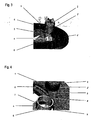
Figur 1 zeigt die Aufsicht auf einen Bereich einer Grundplatte 1 eines Im-Ohr-Hörgerätes mit einem von Aussen bedienbaren Betätigungselement in Form eines Drehschalters 2 resp. Potentiometers. Das Betätigungselement 2 beinhaltet beispielsweise ein Potentiometer, welches über Anschlusslitzen 3 mit weiteren elektronischen Komponenten des Hörgerätes verbunden ist, wie aus der Ansicht auf die Unterseite resp. Innenseite der Grundplatte 1 aus Figur 2 hervorgeht.Figure 1 shows the top view of a portion of a
Erfindungsgemäss ist für die Befestigung des Betätigungselementes 2 in der Grundplatte 1 eine Hülse 4 vorgesehen, welche den Fussbereich 2' des Betätigungselementes 2 umschliesst. In der Grundplatte 1 ist eine Ausnehmung resp. Öffnung 5 ausgebildet, in welche die Hülse 4 zusammen mit dem Betätigungselement 2 eingeschoben werden kann. Die Hülse 4 kann dabei vorteilhaft aus Kunststoff gefertigt sein, alternativ ist aber auch die Verwendung von Metall denkbar.According to the invention a
Aus Figur 3 ist die Aufsicht auf die Grundplatte 1 des Hörgerätes dargestellt, wobei die Hülse 4 in der Öffnung 5 eingesetzt ist, und darüber das Betätigungselement 2 ausserhalb der Öffnung 5 für das Einsetzen in die Grundplatte 1 positioniert ist. Die Anschlusslitzen 3 führen bereits durch die Öffnung 5 in das Innere des Hörgerätes und sind dort mit weiteren elektronischen Komponenten des Hörgerätes verbunden.FIG. 3 shows the top view of the
Das Betätigungselement 2 kann nun in die Hülse 4 eingeführt werden und wird dort festgeklemmt und fixiert. Die Klemmüng erfolgt vorteilhaft durch entsprechende Dimensionierung der Hülse 4 resp. des Fussbereiches 2' des Betätigungselementes. Der Spalt 4' der Hülse 4 unterstützt dabei ein einfaches Einsetzen der Hülse 4 in die Öffnung 5 und erlaubt beim Einsetzen des Betätigungselementes 2 in die Hülse 4 ein leichtes Ausdehnen und damit Klemmen gegen die Innenwand der Öffnung 5 der Grundplatte 1.The
Um das Betätigungselement 2 exakt zu positionieren und ein ungewolltes oder selbständiges Verdrehen um seine Längsachse zu verhindern, sind beispielsweise an der Aussenfläche des Fussbereiches 2' des Betätigungselementes 2 parallel zur Längsachse ausgerichtete Nuten 6 ausgebildet. In diese Nuten 6 greifen entsprechend ausgeformte Rippen 7 der Hülse 4 ein und positionieren damit das Betätigungselement 2 relativ in Bezug auf die Hülse 4 in einer definierten Lage.In order to position the
Die Hülse 4 selbst weist nun an seiner Aussenseite beispielsweise weitere Rippen 8 auf, wie aus Figur 4 ersichtlich ist. Diese Rippen 8 erlauben im Zusammenspiel mit an der Öffnung 5 angeordneten Nuten (nicht dargestellt) eine definierte Positionierung der Hülse 4 relativ zur Grundplatte 1.The
Weiter kann die Hülse 4 nach Aussen abstehende, quer zur Längsachse liegende Vorsprünge oder Flansche aufweisen, welche gegen in der Öffnung 5 ausgebildete Vorsprünge in Anschlag gelangen können. Damit kann eine definierte Eindringtiefe der Hülse 4 in die Grundplatte 1 erzielt werden, um eine exakte Tiefenpositionierung der Hülse 4 resp. des Betätigungselementes 2 zu erreichen. In diesem Bereich der Anschläge können beispielsweise auch Dichtungen angeordnet werden, um das Eindringen von Feuchtigkeit und Schmutz über den Spalt zwischen Hülse 4 und Öffnung 5 zu verhindern.Further, the
Die Hülse 4 kann durch entsprechende geometrische Dimensionierung einen Presssitz zwischen sich und der Grundplatte 1 resp. dem Betätigungselement 2 realisieren. Damit lässt sich das Betätigungselement 2 und die Hülse 4 zu einem späteren Zeitpunkt wieder zerstörungsfrei von der Grundplatte 1 lösen. Denkbar ist auch, dass die Hülse 4 mittels Klebstoff in der Öffnung 5 fixiert wird und damit gleichzeitig eine Abdichtung des Spaltes zwischen Hülse 4 und Öffnung 5 erfolgt.The
In Figur 5 ist dargestellt, wie die Hülse 4 danach dank dem Spalt 4' vom Betätigungselement 2 gelöst resp. entfernt werden kann, ohne dass die Anschlusslitzen 3 entfernt werden müssten. Die Anschlusslitzen 3 können einfach durch den Spalt 4' der Hülse 4 hindurchgeführt werden und danach die Hülse 4 entfernt werden.In Figure 5 is shown how the
Das Betätigungselement 2 kann danach einfach durch die Öffnung 5 in Richtung des Inneren des Hörgerätes resp. in Richtung der weiteren elektronischen Komponenten hindurchgeführt werden, da der grösste Aussendurchmesser des Betätigungselementes 2 vorteilhaft kleiner ist als der Innendurchmesser der Öffnung 5, wie aus der Darstellung in Figur 6 hervorgeht. Damit braucht auch die Grundplatte 1 nicht zerstört zu werden, und die Anschlusslitzen 3 können ebenfalls mit den übrigen elektronischen Komponenten des Hörgerätes verbunden bleiben und für den Einsatz mit einem anderen Gehäuse resp. Grundplatte 1 wieder verwendet werden.The
Claims (10)
Priority Applications (5)
| Application Number | Priority Date | Filing Date | Title |
|---|---|---|---|
| DE502005003062T DE502005003062D1 (en) | 2005-10-31 | 2005-10-31 | Fastening device for actuators of hearing aids resp. hearing aids |
| DK05023790T DK1641316T3 (en) | 2005-10-31 | 2005-10-31 | Device for attaching control elements to hearing aids |
| EP05023790A EP1641316B1 (en) | 2005-10-31 | 2005-10-31 | Device for fixing the control elements of hearing devices resp. hearing aids |
| AT05023790T ATE388603T1 (en) | 2005-10-31 | 2005-10-31 | FASTENING DEVICE FOR ACTUATING ELEMENTS OF HEARING AIDS OR HEARING AIDS |
| CN2006101425748A CN1984510B (en) | 2005-10-31 | 2006-10-30 | Device for fixing the control elements of hearing devices or hearing aids |
Applications Claiming Priority (1)
| Application Number | Priority Date | Filing Date | Title |
|---|---|---|---|
| EP05023790A EP1641316B1 (en) | 2005-10-31 | 2005-10-31 | Device for fixing the control elements of hearing devices resp. hearing aids |
Publications (3)
| Publication Number | Publication Date |
|---|---|
| EP1641316A2 true EP1641316A2 (en) | 2006-03-29 |
| EP1641316A3 EP1641316A3 (en) | 2006-05-17 |
| EP1641316B1 EP1641316B1 (en) | 2008-03-05 |
Family
ID=35355841
Family Applications (1)
| Application Number | Title | Priority Date | Filing Date |
|---|---|---|---|
| EP05023790A Not-in-force EP1641316B1 (en) | 2005-10-31 | 2005-10-31 | Device for fixing the control elements of hearing devices resp. hearing aids |
Country Status (5)
| Country | Link |
|---|---|
| EP (1) | EP1641316B1 (en) |
| CN (1) | CN1984510B (en) |
| AT (1) | ATE388603T1 (en) |
| DE (1) | DE502005003062D1 (en) |
| DK (1) | DK1641316T3 (en) |
Cited By (1)
| Publication number | Priority date | Publication date | Assignee | Title |
|---|---|---|---|---|
| EP2059069A3 (en) * | 2007-11-09 | 2010-08-04 | Siemens Medical Instruments Pte. Ltd. | Faceplate for hearing aids and method for manufacturing same |
Citations (4)
| Publication number | Priority date | Publication date | Assignee | Title |
|---|---|---|---|---|
| WO1986006919A1 (en) * | 1985-05-09 | 1986-11-20 | Cos.El.Gi S.P.A. | Improvement in the faceplates of intracanal hearing aids |
| US4835833A (en) * | 1987-12-02 | 1989-06-06 | Resistance Technology, Inc. | Method of mounting a potentiometer |
| US5157371A (en) * | 1991-01-11 | 1992-10-20 | Resistance Technology, Inc. | Potentiometer retention mechanism and method of mounting |
| EP1564770A2 (en) * | 2004-02-13 | 2005-08-17 | Sonion Roskilde A/S | An integrated volume control and switch assembly |
Family Cites Families (2)
| Publication number | Priority date | Publication date | Assignee | Title |
|---|---|---|---|---|
| CH528198A (en) * | 1971-12-30 | 1972-09-15 | Elektroakustik Ag F | Hearing aid |
| US5014037A (en) * | 1987-12-02 | 1991-05-07 | Mcdonald Gerald H | Potentiometer mounting mechanism |
-
2005
- 2005-10-31 AT AT05023790T patent/ATE388603T1/en not_active IP Right Cessation
- 2005-10-31 DK DK05023790T patent/DK1641316T3/en active
- 2005-10-31 EP EP05023790A patent/EP1641316B1/en not_active Not-in-force
- 2005-10-31 DE DE502005003062T patent/DE502005003062D1/en active Active
-
2006
- 2006-10-30 CN CN2006101425748A patent/CN1984510B/en not_active Expired - Fee Related
Patent Citations (4)
| Publication number | Priority date | Publication date | Assignee | Title |
|---|---|---|---|---|
| WO1986006919A1 (en) * | 1985-05-09 | 1986-11-20 | Cos.El.Gi S.P.A. | Improvement in the faceplates of intracanal hearing aids |
| US4835833A (en) * | 1987-12-02 | 1989-06-06 | Resistance Technology, Inc. | Method of mounting a potentiometer |
| US5157371A (en) * | 1991-01-11 | 1992-10-20 | Resistance Technology, Inc. | Potentiometer retention mechanism and method of mounting |
| EP1564770A2 (en) * | 2004-02-13 | 2005-08-17 | Sonion Roskilde A/S | An integrated volume control and switch assembly |
Cited By (4)
| Publication number | Priority date | Publication date | Assignee | Title |
|---|---|---|---|---|
| EP2059069A3 (en) * | 2007-11-09 | 2010-08-04 | Siemens Medical Instruments Pte. Ltd. | Faceplate for hearing aids and method for manufacturing same |
| EP2249588A2 (en) | 2007-11-09 | 2010-11-10 | Siemens Medical Instruments Pte. Ltd. | Faceplate for hearing aids and method for manufacturing same |
| EP2249588A3 (en) * | 2007-11-09 | 2011-03-09 | Siemens Medical Instruments Pte. Ltd. | Faceplate for hearing aids and method for manufacturing same |
| US8204264B2 (en) | 2007-11-09 | 2012-06-19 | Siemens Medical Instruments Pte. Ltd. | Faceplate for hearing devices and method for producing a faceplate |
Also Published As
| Publication number | Publication date |
|---|---|
| CN1984510A (en) | 2007-06-20 |
| CN1984510B (en) | 2011-11-23 |
| EP1641316A3 (en) | 2006-05-17 |
| EP1641316B1 (en) | 2008-03-05 |
| DK1641316T3 (en) | 2008-06-30 |
| ATE388603T1 (en) | 2008-03-15 |
| DE502005003062D1 (en) | 2008-04-17 |
Similar Documents
| Publication | Publication Date | Title |
|---|---|---|
| EP2301115B1 (en) | Electrical connection device | |
| EP3292604A1 (en) | Arrangement comprising a wall lead-through for a plurality of cables, method for the production thereof and kit | |
| EP2178183A2 (en) | Cable feed for housing of electronic components | |
| DE102018102706B4 (en) | Set of conductor connection clamp and operating tool | |
| EP1641316B1 (en) | Device for fixing the control elements of hearing devices resp. hearing aids | |
| DE202009003696U1 (en) | Device for extracting a tooth root | |
| DE202006010183U1 (en) | Angle measuring device e.g. for rotary encoder, has locking part which can be moved to locking position to limit axial spring movement between machine part and structural unit | |
| EP1797261B1 (en) | Device for actuating a lock in a vehicle | |
| DE102017208590B4 (en) | Device for pressure equalization in a housing | |
| WO2013060521A1 (en) | Apparatus for determining and/or monitoring at least one process variable | |
| DE202008013812U1 (en) | A connector, in particular a cable clamp | |
| DE2930833A1 (en) | CLAMP SLEEVE | |
| EP2068224A2 (en) | Rotating operating device | |
| DE102009007328B4 (en) | Connecting device for connecting two at an angle <180 ° to each other standing plate-shaped elements | |
| DE102020203879A1 (en) | Cooling system | |
| EP0987483A1 (en) | Conductive pipe or cable clamp | |
| DE102008026020A1 (en) | Pressure i.e. differential pressure, measuring device i.e. pneumatic pressure sensor, has channels provided in connection block and partially guided via holder, so that ends of holder are aligned with medium-contacting surfaces and O-rings | |
| DE102010027995B4 (en) | sensor element | |
| BE1027095B1 (en) | Magazine for processing wire end sleeves and hand tools for crimping wire end sleeves | |
| EP2966853B1 (en) | Automation device with mounting aid | |
| DE202018101030U1 (en) | Improved punching device | |
| WO2018033540A1 (en) | Thin conductor with passages | |
| DE10301879B3 (en) | Electrical plug socket element with external fixing thread for securing to mounting plate by partial rotation through less than 360 degrees | |
| EP3404777B1 (en) | Device connection | |
| DE8124893U1 (en) | PLASTIC HOUSING FOR EXTRACTOR FILTER |
Legal Events
| Date | Code | Title | Description |
|---|---|---|---|
| PUAI | Public reference made under article 153(3) epc to a published international application that has entered the european phase |
Free format text: ORIGINAL CODE: 0009012 |
|
| AK | Designated contracting states |
Kind code of ref document: A2 Designated state(s): AT BE BG CH CY CZ DE DK EE ES FI FR GB GR HU IE IS IT LI LT LU LV MC NL PL PT RO SE SI SK TR |
|
| AX | Request for extension of the european patent |
Extension state: AL BA HR MK YU |
|
| PUAL | Search report despatched |
Free format text: ORIGINAL CODE: 0009013 |
|
| RIN1 | Information on inventor provided before grant (corrected) |
Inventor name: GABATHULER, BRUNO |
|
| AK | Designated contracting states |
Kind code of ref document: A3 Designated state(s): AT BE BG CH CY CZ DE DK EE ES FI FR GB GR HU IE IS IT LI LT LU LV MC NL PL PT RO SE SI SK TR |
|
| AX | Request for extension of the european patent |
Extension state: AL BA HR MK YU |
|
| 17P | Request for examination filed |
Effective date: 20061103 |
|
| AKX | Designation fees paid |
Designated state(s): AT BE BG CH CY CZ DE DK EE ES FI FR GB GR HU IE IS IT LI LT LU LV MC NL PL PT RO SE SI SK TR |
|
| GRAP | Despatch of communication of intention to grant a patent |
Free format text: ORIGINAL CODE: EPIDOSNIGR1 |
|
| GRAS | Grant fee paid |
Free format text: ORIGINAL CODE: EPIDOSNIGR3 |
|
| GRAA | (expected) grant |
Free format text: ORIGINAL CODE: 0009210 |
|
| AK | Designated contracting states |
Kind code of ref document: B1 Designated state(s): AT BE BG CH CY CZ DE DK EE ES FI FR GB GR HU IE IS IT LI LT LU LV MC NL PL PT RO SE SI SK TR |
|
| REG | Reference to a national code |
Ref country code: GB Ref legal event code: FG4D Free format text: NOT ENGLISH |
|
| REG | Reference to a national code |
Ref country code: CH Ref legal event code: EP Ref country code: CH Ref legal event code: NV Representative=s name: TROESCH SCHEIDEGGER WERNER AG |
|
| REG | Reference to a national code |
Ref country code: IE Ref legal event code: FG4D Free format text: LANGUAGE OF EP DOCUMENT: GERMAN |
|
| REF | Corresponds to: |
Ref document number: 502005003062 Country of ref document: DE Date of ref document: 20080417 Kind code of ref document: P |
|
| REG | Reference to a national code |
Ref country code: DK Ref legal event code: T3 |
|
| PG25 | Lapsed in a contracting state [announced via postgrant information from national office to epo] |
Ref country code: FI Free format text: LAPSE BECAUSE OF FAILURE TO SUBMIT A TRANSLATION OF THE DESCRIPTION OR TO PAY THE FEE WITHIN THE PRESCRIBED TIME-LIMIT Effective date: 20080305 Ref country code: ES Free format text: LAPSE BECAUSE OF FAILURE TO SUBMIT A TRANSLATION OF THE DESCRIPTION OR TO PAY THE FEE WITHIN THE PRESCRIBED TIME-LIMIT Effective date: 20080616 |
|
| NLV1 | Nl: lapsed or annulled due to failure to fulfill the requirements of art. 29p and 29m of the patents act | ||
| PG25 | Lapsed in a contracting state [announced via postgrant information from national office to epo] |
Ref country code: PL Free format text: LAPSE BECAUSE OF FAILURE TO SUBMIT A TRANSLATION OF THE DESCRIPTION OR TO PAY THE FEE WITHIN THE PRESCRIBED TIME-LIMIT Effective date: 20080305 Ref country code: SI Free format text: LAPSE BECAUSE OF FAILURE TO SUBMIT A TRANSLATION OF THE DESCRIPTION OR TO PAY THE FEE WITHIN THE PRESCRIBED TIME-LIMIT Effective date: 20080305 Ref country code: LV Free format text: LAPSE BECAUSE OF FAILURE TO SUBMIT A TRANSLATION OF THE DESCRIPTION OR TO PAY THE FEE WITHIN THE PRESCRIBED TIME-LIMIT Effective date: 20080305 |
|
| REG | Reference to a national code |
Ref country code: IE Ref legal event code: FD4D |
|
| PG25 | Lapsed in a contracting state [announced via postgrant information from national office to epo] |
Ref country code: PT Free format text: LAPSE BECAUSE OF FAILURE TO SUBMIT A TRANSLATION OF THE DESCRIPTION OR TO PAY THE FEE WITHIN THE PRESCRIBED TIME-LIMIT Effective date: 20080805 Ref country code: SK Free format text: LAPSE BECAUSE OF FAILURE TO SUBMIT A TRANSLATION OF THE DESCRIPTION OR TO PAY THE FEE WITHIN THE PRESCRIBED TIME-LIMIT Effective date: 20080305 Ref country code: CZ Free format text: LAPSE BECAUSE OF FAILURE TO SUBMIT A TRANSLATION OF THE DESCRIPTION OR TO PAY THE FEE WITHIN THE PRESCRIBED TIME-LIMIT Effective date: 20080305 Ref country code: NL Free format text: LAPSE BECAUSE OF FAILURE TO SUBMIT A TRANSLATION OF THE DESCRIPTION OR TO PAY THE FEE WITHIN THE PRESCRIBED TIME-LIMIT Effective date: 20080305 Ref country code: SE Free format text: LAPSE BECAUSE OF FAILURE TO SUBMIT A TRANSLATION OF THE DESCRIPTION OR TO PAY THE FEE WITHIN THE PRESCRIBED TIME-LIMIT Effective date: 20080605 |
|
| PG25 | Lapsed in a contracting state [announced via postgrant information from national office to epo] |
Ref country code: RO Free format text: LAPSE BECAUSE OF FAILURE TO SUBMIT A TRANSLATION OF THE DESCRIPTION OR TO PAY THE FEE WITHIN THE PRESCRIBED TIME-LIMIT Effective date: 20080305 |
|
| EN | Fr: translation not filed | ||
| PG25 | Lapsed in a contracting state [announced via postgrant information from national office to epo] |
Ref country code: IS Free format text: LAPSE BECAUSE OF FAILURE TO SUBMIT A TRANSLATION OF THE DESCRIPTION OR TO PAY THE FEE WITHIN THE PRESCRIBED TIME-LIMIT Effective date: 20080705 |
|
| PLBE | No opposition filed within time limit |
Free format text: ORIGINAL CODE: 0009261 |
|
| STAA | Information on the status of an ep patent application or granted ep patent |
Free format text: STATUS: NO OPPOSITION FILED WITHIN TIME LIMIT |
|
| PG25 | Lapsed in a contracting state [announced via postgrant information from national office to epo] |
Ref country code: IE Free format text: LAPSE BECAUSE OF FAILURE TO SUBMIT A TRANSLATION OF THE DESCRIPTION OR TO PAY THE FEE WITHIN THE PRESCRIBED TIME-LIMIT Effective date: 20080305 Ref country code: LT Free format text: LAPSE BECAUSE OF FAILURE TO SUBMIT A TRANSLATION OF THE DESCRIPTION OR TO PAY THE FEE WITHIN THE PRESCRIBED TIME-LIMIT Effective date: 20080305 |
|
| 26N | No opposition filed |
Effective date: 20081208 |
|
| BERE | Be: lapsed |
Owner name: PHONAK A.G. Effective date: 20081031 |
|
| PG25 | Lapsed in a contracting state [announced via postgrant information from national office to epo] |
Ref country code: BG Free format text: LAPSE BECAUSE OF FAILURE TO SUBMIT A TRANSLATION OF THE DESCRIPTION OR TO PAY THE FEE WITHIN THE PRESCRIBED TIME-LIMIT Effective date: 20080605 Ref country code: FR Free format text: LAPSE BECAUSE OF FAILURE TO SUBMIT A TRANSLATION OF THE DESCRIPTION OR TO PAY THE FEE WITHIN THE PRESCRIBED TIME-LIMIT Effective date: 20081226 Ref country code: EE Free format text: LAPSE BECAUSE OF FAILURE TO SUBMIT A TRANSLATION OF THE DESCRIPTION OR TO PAY THE FEE WITHIN THE PRESCRIBED TIME-LIMIT Effective date: 20080305 |
|
| PG25 | Lapsed in a contracting state [announced via postgrant information from national office to epo] |
Ref country code: MC Free format text: LAPSE BECAUSE OF NON-PAYMENT OF DUE FEES Effective date: 20081031 |
|
| PG25 | Lapsed in a contracting state [announced via postgrant information from national office to epo] |
Ref country code: IT Free format text: LAPSE BECAUSE OF FAILURE TO SUBMIT A TRANSLATION OF THE DESCRIPTION OR TO PAY THE FEE WITHIN THE PRESCRIBED TIME-LIMIT Effective date: 20080305 |
|
| PG25 | Lapsed in a contracting state [announced via postgrant information from national office to epo] |
Ref country code: CY Free format text: LAPSE BECAUSE OF FAILURE TO SUBMIT A TRANSLATION OF THE DESCRIPTION OR TO PAY THE FEE WITHIN THE PRESCRIBED TIME-LIMIT Effective date: 20080305 Ref country code: BE Free format text: LAPSE BECAUSE OF NON-PAYMENT OF DUE FEES Effective date: 20081031 |
|
| PG25 | Lapsed in a contracting state [announced via postgrant information from national office to epo] |
Ref country code: AT Free format text: LAPSE BECAUSE OF NON-PAYMENT OF DUE FEES Effective date: 20081031 |
|
| PG25 | Lapsed in a contracting state [announced via postgrant information from national office to epo] |
Ref country code: HU Free format text: LAPSE BECAUSE OF FAILURE TO SUBMIT A TRANSLATION OF THE DESCRIPTION OR TO PAY THE FEE WITHIN THE PRESCRIBED TIME-LIMIT Effective date: 20080906 Ref country code: LU Free format text: LAPSE BECAUSE OF NON-PAYMENT OF DUE FEES Effective date: 20081031 |
|
| PG25 | Lapsed in a contracting state [announced via postgrant information from national office to epo] |
Ref country code: TR Free format text: LAPSE BECAUSE OF FAILURE TO SUBMIT A TRANSLATION OF THE DESCRIPTION OR TO PAY THE FEE WITHIN THE PRESCRIBED TIME-LIMIT Effective date: 20080305 |
|
| PG25 | Lapsed in a contracting state [announced via postgrant information from national office to epo] |
Ref country code: GR Free format text: LAPSE BECAUSE OF FAILURE TO SUBMIT A TRANSLATION OF THE DESCRIPTION OR TO PAY THE FEE WITHIN THE PRESCRIBED TIME-LIMIT Effective date: 20080606 |
|
| PG25 | Lapsed in a contracting state [announced via postgrant information from national office to epo] |
Ref country code: GB Free format text: LAPSE BECAUSE OF NON-PAYMENT OF DUE FEES Effective date: 20091031 |
|
| PGFP | Annual fee paid to national office [announced via postgrant information from national office to epo] |
Ref country code: DK Payment date: 20131025 Year of fee payment: 9 |
|
| PGFP | Annual fee paid to national office [announced via postgrant information from national office to epo] |
Ref country code: CH Payment date: 20131029 Year of fee payment: 9 Ref country code: DE Payment date: 20131029 Year of fee payment: 9 |
|
| REG | Reference to a national code |
Ref country code: DE Ref legal event code: R119 Ref document number: 502005003062 Country of ref document: DE |
|
| REG | Reference to a national code |
Ref country code: DK Ref legal event code: EBP Effective date: 20141031 |
|
| REG | Reference to a national code |
Ref country code: CH Ref legal event code: PL |
|
| PG25 | Lapsed in a contracting state [announced via postgrant information from national office to epo] |
Ref country code: CH Free format text: LAPSE BECAUSE OF NON-PAYMENT OF DUE FEES Effective date: 20141031 Ref country code: DE Free format text: LAPSE BECAUSE OF NON-PAYMENT OF DUE FEES Effective date: 20150501 Ref country code: LI Free format text: LAPSE BECAUSE OF NON-PAYMENT OF DUE FEES Effective date: 20141031 |
|
| PG25 | Lapsed in a contracting state [announced via postgrant information from national office to epo] |
Ref country code: DK Free format text: LAPSE BECAUSE OF NON-PAYMENT OF DUE FEES Effective date: 20141031 |