EP1640706A1 - Wellenlängen- und Einfallswinkel-aufgelöstes Ellipsometer oder Reflektometer - Google Patents
Wellenlängen- und Einfallswinkel-aufgelöstes Ellipsometer oder Reflektometer Download PDFInfo
- Publication number
- EP1640706A1 EP1640706A1 EP04292275A EP04292275A EP1640706A1 EP 1640706 A1 EP1640706 A1 EP 1640706A1 EP 04292275 A EP04292275 A EP 04292275A EP 04292275 A EP04292275 A EP 04292275A EP 1640706 A1 EP1640706 A1 EP 1640706A1
- Authority
- EP
- European Patent Office
- Prior art keywords
- sample
- wavelength
- plane
- surface portion
- light distribution
- Prior art date
- Legal status (The legal status is an assumption and is not a legal conclusion. Google has not performed a legal analysis and makes no representation as to the accuracy of the status listed.)
- Withdrawn
Links
Images

Classifications
-
- G—PHYSICS
- G01—MEASURING; TESTING
- G01N—INVESTIGATING OR ANALYSING MATERIALS BY DETERMINING THEIR CHEMICAL OR PHYSICAL PROPERTIES
- G01N21/00—Investigating or analysing materials by the use of optical means, i.e. using sub-millimetre waves, infrared, visible or ultraviolet light
- G01N21/17—Systems in which incident light is modified in accordance with the properties of the material investigated
- G01N21/21—Polarisation-affecting properties
- G01N21/211—Ellipsometry
-
- G—PHYSICS
- G01—MEASURING; TESTING
- G01N—INVESTIGATING OR ANALYSING MATERIALS BY DETERMINING THEIR CHEMICAL OR PHYSICAL PROPERTIES
- G01N21/00—Investigating or analysing materials by the use of optical means, i.e. using sub-millimetre waves, infrared, visible or ultraviolet light
- G01N21/17—Systems in which incident light is modified in accordance with the properties of the material investigated
- G01N21/55—Specular reflectivity
Definitions
- the invention relates to an apparatus for determining reflectivity and/or ellipsometric properties of a sample.
- Reflectivity as well as ellipsometric properties are extensively used to characterize optical coatings or complex multilayer structures, like for example used in microelectronic and/or optical coatings applications.
- To determine those characteristics, like film thickness, refractive indices, etc. experimentally obtained values of the reflectivity coefficients or the ellipsometry parameters ⁇ and ⁇ are compared to theoretical models from which the physical parameters one is interested in are extracted.
- state of the art ellipsometers determine simultaneously the Phi and Delta parameters either for a plurality of incidence angles or for a plurality of wavelengths. Even though theoretically proposed, an ellipsometer which is capable of measuring at the same time reflectance for a plurality of angles and a plurality of wavelengths has not yet been achieved. This is mainly due to the fact that in state of the art ellipsometers a converging lens is used to focalize the incoming light on one point of the surface of a sample and a second lens is employed to collimate the reflected light beam which then is detected by a one- or two-dimensional detector wherein the pixel positions are related to the angles of incidence.
- Using the Fourier transform properties of a lens is a very elegant way to transform an angular light distribution into a positional light distribution.
- the illumination is made at a plurality of angles using the Fourier lens.
- the applicant has already used this kind of optical arrangement, details of which can be found in FR2613830.
- the reflected angular light distribution of the multi wavelength light beam is transformed into a positional light distribution by the same Fourier lens. This positional light distribution at the Fourier plane is already angle resolved and in order to obtain the spectral information out of the reflected beam this distribution is imaged using the second optical system onto the entrance slit.
- any wavelength dispersing spectrograph can be used, under the condition that the light gets dispersed essentially perpendicular to the large dimension of the entrance slit. This ensures that on the detector placed at the exit of the spectrograph the axis along the extension of the entrance slit corresponds to changing incidence angle and the axis perpendicular corresponds to reflectance changing with wavelength.
- Suitable as a detector here is any two-dimensional detector having a certain resolution, such as for example a CCD sensor. The number of pixels will determine both the wavelength and the incidence angle resolution due to the size of the pixels.
- the apparatus is less sensitive with respect to sample and optics alignment and is furthermore relatively independent of spot size variations on the sample, which are limiting factors of state of the art ellipsometers.
- the illumination device can further comprise a slit arranged and configured such that the multi wavelength light beam is illuminating the sample under a plurality of angles essentially in a plane defined by the optical axis of the apparatus and the entrance slit of the imaging spectrograph.
- the illumination device can be configured to illuminate a sample under incident angles being at least within a range of about 0 - 45°, more preferably 0 - 80° with respect to the normal sample surface. Thanks to the Fourier optic it thus becomes possible to resolve the reflectivity and/or ellipsometric properties within a large incidence angle range compared to prior art reflectometers, thus allowing the collection of a large amount of experimental data at a same time.
- the apparatus can further comprise an adjustable diaphragm positioned between the Fourier lens and the entrance slit to define the size of the surface portion to be analyzed.
- an adjustable diaphragm positioned between the Fourier lens and the entrance slit to define the size of the surface portion to be analyzed.
- the apparatus can further comprise a first polarizer positioned in front of the entrance slit of the imaging spectrograph to linearly polarize the reflected multi wavelength light beam, in particular in a plane defined by the incident and the reflected light (p-plane) or in the plane perpendicular to the p-plane (s-plane).
- a first polarizer positioned in front of the entrance slit of the imaging spectrograph to linearly polarize the reflected multi wavelength light beam, in particular in a plane defined by the incident and the reflected light (p-plane) or in the plane perpendicular to the p-plane (s-plane).
- the illumination device can further comprise a second polarizer to linearly polarize the multi wavelength light beam, in particular in the p-plane or in the s-plane.
- the introduction of the second polarizer, in particular positioned behind the illumination slit with respect to the light propagation, can be used to control the polarization state of the light beam prior to reflecting on the sample surface.
- the first polarizer before the entrance slit of the spectrograph is used to analyze the variation of polarization of the light beam after reflection on the sample surface. This will allow the measurement of the complex ratio R P /R S and/or of the standard ellipsometric parameters ⁇ and ⁇ becomes possible. Together with the simultaneous measurement of a plurality of incidence angles and wavelengths a very powerful apparatus to analyze complex multilayer structures is thus obtained.
- the first and/or second polarizer is rotatably arranged thereby allowing to change the polarization plane, particularly from the p-plane to the s-plane and vice versa.
- Such a rotation of the polarizer can be used to get further experimental data to obtain more precise information on the physical properties of the sample.
- the apparatus can further comprise a third optical system positioned between the adjustable diaphragm and the entrance slit of the imaging spectrograph being configured such that the surface portion to be analyzed is observable. Using the image of the surface portion of the sample which is going to analyzed allows to well position the sample with respect to the optical elements and furthermore also allows to find a suitable spot on the surface.
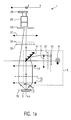
- Figs. 1 a and 1b illustrate an apparatus 1 for determining simultaneously wavelength and incidence angle resolved reflectivity and/or ellipsometric properties of a sample 3 according to a first embodiment of the invention. Elements of apparatus 1 illustrated in dashed lines are optional and their addition to the apparatus 1 lead to further variants of the first embodiment.
- Parts of the apparatus 1 related to the Fourier optics are similar to the design of an apparatus for measuring photometric and colorimetric characteristics of an object disclosed in US5,880,845 applied to the characterization of reflective displays of the same applicant.
- the apparatus 1 has an illumination device 5 used to illuminate a surface portion 7 of the sample 3.
- This illumination device 5 comprises a light source 9 preferably emitting light with a plurality of wavelengths, in particular white light, such as for example a xenon or tungsten halogen lamp emitting light within a wavelength range of about 200nm to 1000nm.
- the light source 9 is imaged using a first and a second lens 11, 13 onto the focal plane 15 of a third lens 17.
- the multi wavelength light beam hits the surface of the sample 3, positioned in the conjugate focal plane 19 of the third lens 17, under a plurality of incident angles ⁇ .
- the proposed optical arrangement furthermore allows to illuminate not only a spot but a certain surface portion 7 of the sample 3. With the proposed optical arrangement incidence angles in a range of up to 80° with respect to the normal of the surface of the sample 3 are obtained.
- the illumination device 5 further comprises a mirror or a beamsplitter 21 so that the light source 9 can be shifted away from the optical axis o.a. of the apparatus 1.
- the illumination device 5 comprises three lenses 11, 13 and 17 as well as a mirror 21.
- this arrangement corresponds only to one possible arrangement and illumination devices 5 with less than three or more than three lenses and with or without mirror can be realized, as long as the requirement that the sample 3 is illuminated with multi wavelength light under a plurality of incident angles is satisfied.
- the proposed design of the illumination device 5 has furthermore the advantage that at least a part of the lenses, here the second and third lens 13, 17 can be shared with the optical systems placed in the reflected beam and which will be described in the following.
- the third lens 17 corresponds to the Fourier lens which is configured to transform the angular light distribution of the reflected light beam into a positional light distribution in the Fourier plane, which is the focal plane 15 of the third lens 17.
- the first optical system according to the invention is composed of only one lens.
- the positional light distribution obtained in the focal plane 15 of the third lens 17 is then imaged onto an entrance slit 23 of a spectrograph 25 using a second optical system comprising two lenses, namely the second lens 13, shared with the illumination device 5, and a fourth lens 27.
- the number of lenses in the second optical system may be varied as long as the positional light distribution in the focal plane 15 is imaged onto the entrance slit 23 of the spectrograph 25.
- the entrance slit 23 has its large dimension in the X direction and a relatively small extension in the Y direction, perpendicular to the plane of Fig. 1 a.
- the spectrograph 25 which is configured to disperse light depending on the wavelength in the y direction.
- the spectrograph 25 can be any suitable imaging spectrograph under the condition that it disperses light in the Y direction as a function of wavelength.
- a detector 27 which comprises a predetermined amount of pixels arranged in a two-dimensional matrix, like for example a CCD detector.
- the CCD detector will detect the angular dependence of the reflectivity and along the other direction, here the Y direction, the CCD detector will detect the wavelength dependence of the reflectivity.
- the overall resolution thereby depends on the amount of pixels per unit area of the detector 27.
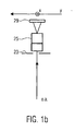
- Fig. 1 b shows a cut of the spectrograph portion of the apparatus 1 in the plane defined by the optical axis o.a. of the apparatus 1 and the Y direction.
- the dimension of the slit 23 is small so that only light traveling in the plane defined by the optical axis o.a. and the X direction enters the spectrograph 25 which in turn disperses light of different wavelengths in the Y direction so that the detector 29 then detects wavelength resolved reflectivity along its Y direction.
- the illumination device 5 can comprise a slit 31 which, like the entrance slit 23 of the spectrograph 25, has its small dimension in the Y direction, so that the light beam is already prior to reflecting on the sample 3 essentially confined to the plane defined by the optical axis o.a. and the X direction. This will reduce the presence of off-specular reflected intensities in the detected intensities which ameliorates the quality of the measured data.
- an adjustable diaphragm 33 can be positioned in the reflected beam allowing to control the size of the surface portion 7 of sample 3 to be analyzed.
- a first polarizer 35 may be placed in the reflected beam to linearly polarize the reflected beam.
- this first polarizer 35 is rotatably arranged so that the polarization direction of the reflected beam can be changed.
- a second polarizer 37 may be positioned in the illumination device 5 to already linearly polarize the light prior to the reflecting from the surface of the sample 3.
- the sample 3 could be mounted on a rotatable stage having its rotation axis essentially parallel to the optical axis o.a., such that reflectivity and/or ellipsometric properties can be measured for various azimuthal alignments of the sample.
- a measurement for one azimuthal position is, however, usually sufficient.
- Fig. 2 illustrates a second embodiment of the apparatus for determining simultaneously wavelength and incidence angle resolved reflectivity and/or elipsometric properties of a sample 3.
- Elements of the second embodiment with the same reference numerals like the ones of embodiment one illustrated in Fig. 1 correspond to those and are not explained in detail again, however their description is enclosed herewith by reference.
- the second embodiment furthermore comprises a third optical system 51 positioned between the adjustable diaphragm 33 and the entrance slit 23 of the spectrograph 25.
- This third optical system 51 is used to image the illuminated spot on the surface of the sample 3 and can thus be used to find the correct spot, which one wishes to analyze, as well as to see whether the sample 3 is well aligned with respect to the focal plane 19.
- the third optical system 51 comprises a mirror 53, reflecting a portion of the reflected light beam away from the optical axis o.a. towards a fifth lens 55 used to image the illuminated spot on sample 3 onto a viewing means 57 which can for example be a screen, the detector 29 or directly the eye of an operator.
- the apparatus 1 or 1' is used in the following way.
- the sample 3 is aligned in the focal plane 19 of the third lens 17. Then sample 3 is illuminated with a multi wavelength light beam under a plurality of angles and the third lens 17 creates the Fourier transform of the reflected beam in its focal plane 15. Thereby the angle resolved information is transformed into a positional resolved information.
- the reflected light carrying the reflectivity and/or ellipsometric information then enters the spectrograph 25 via the slit 23. There for each incidence angle, now corresponding to a certain position in x direction, the wavelength dependency is resolved such that the pixels of detector 29 detect angular and wavelength resolved intensities.
- Those intensities are calibrated using a reference sample in order to obtain the reflection coefficients and can then be analyzed by a computer using a theoretical model to find the thin film parameter the user is interested in. Those comprise for example film thicknesses, refractive indices, interface roughness etc.. If the user is in addition interested in polarization resolved reflectance values (e.g. R P and R S ) the first polarizer 35 is introduced in the reflected beam and by simply rotating it by 90° the two reflectance values R P and R S can be obtained.
- polarization resolved reflectance values e.g. R P and R S
- the second polarizer 37 is introduced in the illumination device 5 to polarize the light prior to reflecting from the sample 3 and different intensity measurements are performed for fixed polarizer 35 position and variable polarizer 37 positions. Usually only four positions are necessary to get the ellipsometric parameters.
- the spot size on the sample 3 of the portion to be analyzed can easily be adjusted and furthermore using the third optical system 51 the alignment of the sample 3 with respect to the focal plane 19 can be easily achieved and the position of the measurement spot on the sample surface 7 can be selected.
- the present invention provides an apparatus which delivers simultaneously an extensive amount of experimental data to characterize thin films or multilayer structures and which at the same time is suitable for a high volume production process.
Landscapes
- Physics & Mathematics (AREA)
- Health & Medical Sciences (AREA)
- Life Sciences & Earth Sciences (AREA)
- Chemical & Material Sciences (AREA)
- Analytical Chemistry (AREA)
- Biochemistry (AREA)
- General Health & Medical Sciences (AREA)
- General Physics & Mathematics (AREA)
- Immunology (AREA)
- Pathology (AREA)
- Investigating Or Analysing Materials By Optical Means (AREA)
Priority Applications (2)
| Application Number | Priority Date | Filing Date | Title |
|---|---|---|---|
| EP04292275A EP1640706A1 (de) | 2004-09-22 | 2004-09-22 | Wellenlängen- und Einfallswinkel-aufgelöstes Ellipsometer oder Reflektometer |
| PCT/EP2005/010225 WO2006032485A1 (en) | 2004-09-22 | 2005-09-21 | Wavelength and incidence angle resolved ellipsometer or reflectometer |
Applications Claiming Priority (1)
| Application Number | Priority Date | Filing Date | Title |
|---|---|---|---|
| EP04292275A EP1640706A1 (de) | 2004-09-22 | 2004-09-22 | Wellenlängen- und Einfallswinkel-aufgelöstes Ellipsometer oder Reflektometer |
Publications (1)
| Publication Number | Publication Date |
|---|---|
| EP1640706A1 true EP1640706A1 (de) | 2006-03-29 |
Family
ID=34931403
Family Applications (1)
| Application Number | Title | Priority Date | Filing Date |
|---|---|---|---|
| EP04292275A Withdrawn EP1640706A1 (de) | 2004-09-22 | 2004-09-22 | Wellenlängen- und Einfallswinkel-aufgelöstes Ellipsometer oder Reflektometer |
Country Status (2)
| Country | Link |
|---|---|
| EP (1) | EP1640706A1 (de) |
| WO (1) | WO2006032485A1 (de) |
Cited By (10)
| Publication number | Priority date | Publication date | Assignee | Title |
|---|---|---|---|---|
| US7502104B2 (en) | 2006-08-10 | 2009-03-10 | Kla-Tencor Corporation | Probe beam profile modulated optical reflectance system and methods |
| CN101910817A (zh) * | 2008-05-28 | 2010-12-08 | 株式会社尼康 | 空间光变频器的检查装置及检查方法、照明光学系统、照明光学系统的调整方法、曝光装置、以及器件制造方法 |
| US8045179B1 (en) | 2008-07-30 | 2011-10-25 | Kla-Tencor Corporation | Bright and dark field scatterometry systems for line roughness metrology |
| CN103884656A (zh) * | 2014-02-20 | 2014-06-25 | 南京邮电大学 | 微纳光谱成像装置 |
| US20160131581A1 (en) * | 2013-07-15 | 2016-05-12 | Shenyang Institute Of Automation Of The Chinese Ac Ademy Of Sciences | In-situ on-line detection device and method for long-distance metallurgical liquid metal component |
| WO2018146681A1 (en) | 2017-02-08 | 2018-08-16 | Yissum Research Development Company Of The Hebrew University Of Jerusalem Ltd. | System and method for use in high spatial resolution ellipsometry |
| CN110082900A (zh) * | 2013-08-22 | 2019-08-02 | 加州理工学院 | 可变照明傅立叶重叠关联成像设备、系统以及方法 |
| CN112041645A (zh) * | 2018-03-29 | 2020-12-04 | 埃尔迪姆公司 | 允许同时测量对象的角度和光谱发射的光学装置 |
| US11092795B2 (en) | 2016-06-10 | 2021-08-17 | California Institute Of Technology | Systems and methods for coded-aperture-based correction of aberration obtained from Fourier ptychography |
| US11468557B2 (en) | 2014-03-13 | 2022-10-11 | California Institute Of Technology | Free orientation fourier camera |
Families Citing this family (4)
| Publication number | Priority date | Publication date | Assignee | Title |
|---|---|---|---|---|
| KR102330741B1 (ko) | 2012-06-26 | 2021-11-23 | 케이엘에이 코포레이션 | 각도 분해형 반사율 측정에서의 스캐닝 및 광학 계측으로부터 회절의 알고리즘적 제거 |
| US10816464B2 (en) * | 2019-01-23 | 2020-10-27 | Applied Materials, Inc. | Imaging reflectometer |
| CN113777048B (zh) * | 2021-08-11 | 2023-07-25 | 华中科技大学 | 一种共轴超快光谱椭偏仪及测量方法 |
| CN113777049B (zh) * | 2021-08-11 | 2023-09-01 | 华中科技大学 | 一种角分辨快照椭偏仪及其测量系统与方法 |
Citations (2)
| Publication number | Priority date | Publication date | Assignee | Title |
|---|---|---|---|---|
| WO2001031303A1 (fr) * | 1999-10-26 | 2001-05-03 | Eldim | Dispositif de mesure de la repartition spatiale de l'emission spectrale d'un objet |
| US20020024668A1 (en) * | 2000-05-26 | 2002-02-28 | Jean-Louis Stehle | Method and apparatus for ellipsometric metrology for a sample contained in a chamber or the like |
-
2004
- 2004-09-22 EP EP04292275A patent/EP1640706A1/de not_active Withdrawn
-
2005
- 2005-09-21 WO PCT/EP2005/010225 patent/WO2006032485A1/en active Application Filing
Patent Citations (2)
| Publication number | Priority date | Publication date | Assignee | Title |
|---|---|---|---|---|
| WO2001031303A1 (fr) * | 1999-10-26 | 2001-05-03 | Eldim | Dispositif de mesure de la repartition spatiale de l'emission spectrale d'un objet |
| US20020024668A1 (en) * | 2000-05-26 | 2002-02-28 | Jean-Louis Stehle | Method and apparatus for ellipsometric metrology for a sample contained in a chamber or the like |
Non-Patent Citations (3)
| Title |
|---|
| BOHER P ET AL: "Innovative rapid photo-goniometry method for CD metrology", PROCEEDINGS OF THE SPIE - THE INTERNATIONAL SOCIETY FOR OPTICAL ENGINEERING SPIE-INT. SOC. OPT. ENG USA, vol. 5375, no. 1, May 2004 (2004-05-01), pages 1302 - 1313, XP002315685, ISSN: 0277-786X * |
| PETIT J ET AL: "A new analysis strategy for CD metrology using rapid photo goniometry method", PROCEEDINGS OF THE SPIE - THE INTERNATIONAL SOCIETY FOR OPTICAL ENGINEERING SPIE-INT. SOC. OPT. ENG USA, vol. 5375, no. 1, May 2004 (2004-05-01), pages 210 - 221, XP002315686, ISSN: 0277-786X * |
| SUSHKOV A B ET AL: "ELLIPSOMETRY OF A CONVERGENT BEAM IN THE FAR INFRARED", OPTICS AND SPECTROSCOPY, AMERICAN INSTITUTE OF PHYSICS. WASHINGTON, US, vol. 72, no. 2, 1 February 1992 (1992-02-01), pages 265 - 268, XP000316247, ISSN: 0030-400X * |
Cited By (16)
| Publication number | Priority date | Publication date | Assignee | Title |
|---|---|---|---|---|
| US7502104B2 (en) | 2006-08-10 | 2009-03-10 | Kla-Tencor Corporation | Probe beam profile modulated optical reflectance system and methods |
| CN101910817A (zh) * | 2008-05-28 | 2010-12-08 | 株式会社尼康 | 空间光变频器的检查装置及检查方法、照明光学系统、照明光学系统的调整方法、曝光装置、以及器件制造方法 |
| EP2282188A1 (de) * | 2008-05-28 | 2011-02-09 | Nikon Corporation | Inspektionsgerät und inspektionsverfahren für einen licht-raum-modulator, optisches beleuchtungssystem, verfahren zur einstellung des optischen beleuchtungssystems, belichtungsgerät und geräteherstellungsverfahren |
| EP2282188A4 (de) * | 2008-05-28 | 2013-10-30 | Nikon Corp | Inspektionsgerät und inspektionsverfahren für einen licht-raum-modulator, optisches beleuchtungssystem, verfahren zur einstellung des optischen beleuchtungssystems, belichtungsgerät und geräteherstellungsverfahren |
| US8045179B1 (en) | 2008-07-30 | 2011-10-25 | Kla-Tencor Corporation | Bright and dark field scatterometry systems for line roughness metrology |
| US9797835B2 (en) * | 2013-07-15 | 2017-10-24 | Shenyang Institute Of Automation Of The Chinese Academy Of Sciences | In-situ on-line detection device and method for long-distance metallurgical liquid metal component |
| US20160131581A1 (en) * | 2013-07-15 | 2016-05-12 | Shenyang Institute Of Automation Of The Chinese Ac Ademy Of Sciences | In-situ on-line detection device and method for long-distance metallurgical liquid metal component |
| CN110082900A (zh) * | 2013-08-22 | 2019-08-02 | 加州理工学院 | 可变照明傅立叶重叠关联成像设备、系统以及方法 |
| CN110082900B (zh) * | 2013-08-22 | 2022-05-13 | 加州理工学院 | 可变照明傅立叶重叠关联成像设备、系统以及方法 |
| CN103884656B (zh) * | 2014-02-20 | 2016-03-02 | 南京邮电大学 | 微纳光谱成像装置 |
| CN103884656A (zh) * | 2014-02-20 | 2014-06-25 | 南京邮电大学 | 微纳光谱成像装置 |
| US11468557B2 (en) | 2014-03-13 | 2022-10-11 | California Institute Of Technology | Free orientation fourier camera |
| US11092795B2 (en) | 2016-06-10 | 2021-08-17 | California Institute Of Technology | Systems and methods for coded-aperture-based correction of aberration obtained from Fourier ptychography |
| WO2018146681A1 (en) | 2017-02-08 | 2018-08-16 | Yissum Research Development Company Of The Hebrew University Of Jerusalem Ltd. | System and method for use in high spatial resolution ellipsometry |
| US11262293B2 (en) | 2017-02-08 | 2022-03-01 | Ralfy KENAZ | System and method for use in high spatial resolution ellipsometry |
| CN112041645A (zh) * | 2018-03-29 | 2020-12-04 | 埃尔迪姆公司 | 允许同时测量对象的角度和光谱发射的光学装置 |
Also Published As
| Publication number | Publication date |
|---|---|
| WO2006032485A1 (en) | 2006-03-30 |
Similar Documents
| Publication | Publication Date | Title |
|---|---|---|
| WO2006032485A1 (en) | Wavelength and incidence angle resolved ellipsometer or reflectometer | |
| JP4880791B2 (ja) | 試料の偏光計スペクトルおよび他の特性を測定するシステム | |
| CN107003114B (zh) | 光谱光束轮廓计量 | |
| US5581350A (en) | Method and system for calibrating an ellipsometer | |
| KR960013677B1 (ko) | 박막 두께 측정 장치 | |
| US10444161B2 (en) | Systems and methods for metrology with layer-specific illumination spectra | |
| JP3995579B2 (ja) | 膜厚測定装置および反射率測定装置 | |
| JP5472096B2 (ja) | サンプルの平面の反射表面を検査する撮像光学検査装置及び方法 | |
| US20050248773A1 (en) | Beam profile complex reflectance system and method for thin film and critical dimension measurements | |
| US7929139B2 (en) | Spectroscopic ellipsometer, film thickness measuring apparatus, and method of focusing in spectroscopic ellipsometer | |
| JP2005515465A (ja) | 偏光を減らした分光計及びそのための多数素子偏光解消装置 | |
| EP3580546A1 (de) | System und verfahren zur verwendung in der ellipsometrie mit hoher räumlicher auflösung | |
| US20090066953A1 (en) | Spectroscopic ellipsometer and film thickness measuring apparatus | |
| KR100923271B1 (ko) | 샘플의 엘립소메트릭 2차원 디스플레이용 장치,디스플레이 방법, 및 공간 분해능을 갖는 엘립소메트릭측정 방법 | |
| US6795185B2 (en) | Film thickness measuring apparatus | |
| JP4716993B2 (ja) | マイクロエレクトロニクスにおける寸法検査のための光学フーリエ変換の使用 | |
| JP3219462B2 (ja) | 薄膜測定器 | |
| JP3765036B2 (ja) | 測定試料の光学的評価方法およびその装置 | |
| Becker | 29‐3: High‐Resolution Scatter Analysis of Anti‐Glare Layer Reflection | |
| FR3087539A1 (fr) | Instrument de mesure avec systeme de visualisation du spot de mesure et accessoire de visualisation pour un tel instrument de mesure | |
| US20110170097A1 (en) | Fiber-Based Optical Probe With Decreased Sample-Positioning Sensitivity | |
| Boher et al. | Light-scattered measurements using Fourier optics: a new tool for surface characterization |
Legal Events
| Date | Code | Title | Description |
|---|---|---|---|
| PUAI | Public reference made under article 153(3) epc to a published international application that has entered the european phase |
Free format text: ORIGINAL CODE: 0009012 |
|
| AK | Designated contracting states |
Kind code of ref document: A1 Designated state(s): AT BE BG CH CY CZ DE DK EE ES FI FR GB GR HU IE IT LI LU MC NL PL PT RO SE SI SK TR |
|
| AX | Request for extension of the european patent |
Extension state: AL HR LT LV MK |
|
| 17P | Request for examination filed |
Effective date: 20060911 |
|
| AKX | Designation fees paid |
Designated state(s): DE FR GB |
|
| 17Q | First examination report despatched |
Effective date: 20061128 |
|
| STAA | Information on the status of an ep patent application or granted ep patent |
Free format text: STATUS: THE APPLICATION IS DEEMED TO BE WITHDRAWN |
|
| 18D | Application deemed to be withdrawn |
Effective date: 20070411 |