EP1640689A2 - Magnetic inclination sensor - Google Patents
Magnetic inclination sensor Download PDFInfo
- Publication number
- EP1640689A2 EP1640689A2 EP05019337A EP05019337A EP1640689A2 EP 1640689 A2 EP1640689 A2 EP 1640689A2 EP 05019337 A EP05019337 A EP 05019337A EP 05019337 A EP05019337 A EP 05019337A EP 1640689 A2 EP1640689 A2 EP 1640689A2
- Authority
- EP
- European Patent Office
- Prior art keywords
- inclination sensor
- case
- detecting means
- pendulum
- magnetism detecting
- Prior art date
- Legal status (The legal status is an assumption and is not a legal conclusion. Google has not performed a legal analysis and makes no representation as to the accuracy of the status listed.)
- Withdrawn
Links
Images


Classifications
-
- G—PHYSICS
- G01—MEASURING; TESTING
- G01C—MEASURING DISTANCES, LEVELS OR BEARINGS; SURVEYING; NAVIGATION; GYROSCOPIC INSTRUMENTS; PHOTOGRAMMETRY OR VIDEOGRAMMETRY
- G01C9/00—Measuring inclination, e.g. by clinometers, by levels
- G01C9/02—Details
- G01C9/06—Electric or photoelectric indication or reading means
-
- G—PHYSICS
- G01—MEASURING; TESTING
- G01C—MEASURING DISTANCES, LEVELS OR BEARINGS; SURVEYING; NAVIGATION; GYROSCOPIC INSTRUMENTS; PHOTOGRAMMETRY OR VIDEOGRAMMETRY
- G01C9/00—Measuring inclination, e.g. by clinometers, by levels
- G01C9/12—Measuring inclination, e.g. by clinometers, by levels by using a single pendulum plumb lines G01C15/10
-
- G—PHYSICS
- G01—MEASURING; TESTING
- G01C—MEASURING DISTANCES, LEVELS OR BEARINGS; SURVEYING; NAVIGATION; GYROSCOPIC INSTRUMENTS; PHOTOGRAMMETRY OR VIDEOGRAMMETRY
- G01C9/00—Measuring inclination, e.g. by clinometers, by levels
- G01C9/02—Details
- G01C9/06—Electric or photoelectric indication or reading means
- G01C2009/064—Electric or photoelectric indication or reading means inductive
Definitions
- the present invention relates to an inclination sensor, and more particularly to a small magnetic inclination sensor that is used in a digital camera, a video camera, and the like.
- a small magnetic inclination sensor there is, for example, an inclination senor disclosed in JP-A-2000-146580.
- a polarized movement is axially supported on a case to turn freely and, when the case turns by a predetermined angle or more, hall elements arranged on the case detect magnetic force of the movement. Consequently, the inclination sensor detects an inclination state of the case.
- the inclination sensor is susceptible to an external magnetic field.
- the movement is affected by the magnetic force to turn.
- the inclination sensor outputs a signal indicating an inclination state despite the fact that the case is not inclined. Therefore, in using the inclination sensor, it is necessary to design the inclination sensor to avoid influence of an external magnetic field.
- a burden in design of an electronic apparatus incorporated with the inclination sensor is large and a degree of freedom of the design is small.
- an electronic apparatus such as a digital camera
- the invention has been devised in view of the problems and it is an object of the invention to provide an inclination sensor that is less affected by an external magnetic field and has a wide applicable range.
- an inclination sensor includes: a case having a turning shaft section projected in a lateral direction on a front surface thereof; magnetism detecting means fixed on an upper side of the turning shaft section; a pair of magnets fixed in parallel to a rear surface of the case to be located on both sides of the magnetism detecting means; a pendulum axially supported by the turning shaft section to turn freely; and a pair of ferromagnetic bodies fixed on an inward surface of the pendulum.
- the magnets are fixed to the rear surface of the case and are not fixed to the pendulum.
- the pendulum is never affected by an external magnetic field to turn and malfunction. Therefore, in designing an electronic apparatus that is reduced in size and has high density, it is unnecessary to design the electronic apparatus to avoid influence of an external magnetic field. As a result, an inclination sensor that is convenient for use and has a wide applicable range is obtained.
- the magnetism detecting means may be a hall IC consisting of at least one hall element.
- the pendulum and the ferromagnetic bodies maybe integrally formed of an identical magnetic material.
- an inclination sensor having a small number of components, a small number of assembly man-hours, and high productivity is obtained.
- a projected portion for positional regulation may be provided on at least one of opposed surfaces of the case and the pendulum, and a recessed portion for positional regulation, in which the projected portion for positional regulation locks, may be provided on the other opposed surface.
- the projected portion for positional regulation can lock on an inner peripheral surface of the recessed portion for positional regulation to regulate swing and turn of the pendulum and prevent malfunction.
- An inclination sensor includes, as shown in Figs. 1 to 10, a case 10, a hall IC 20 serving as magnetism detecting means, a pair of permanent magnets 25 and 26, a pendulum 30 assembled with a pair of ferromagnetic bodies 35 and 36, and a cover 40.
- a size of an inclination sensor body according to this embodiment is 7mm wide, 7 mm high, and 2 mm thick.
- the case 10 is a resin molded product having a substantially square box shape in front in which four lead terminals 11, 12, 13, and 14 are insert-molded.
- a turning shaft section 15 is projected in a lateral direction in a front center of the case 10.
- a housing recessed portion 16, which houses a hall IC 20 described later, and a recessed portion 17 for positional regulation, which positionally regulates an operation of a pendulum 30 described later, are provided in positions opposed to each other in a vertical direction across the turning shaft section 15.
- Connecting sections 11a to 14a of the lead terminals 11 to 14 are exposed at an opening edge of the housing recessed portion 16.
- fitting recessed portions 18a and 18b in which the pair of square magnets 25 and 26 are fit in and fixed, are formed on a rear surface of the case 10.
- engaging projected portions 19 are projected on outside surfaces of the case 10 opposed to each other.
- the hall IC 20 has an external shape capable of housing the hall IC 20 in the housing recessed portion 16.
- the hall IC 20 has a circular magnetic flux detecting area (not shown) is the center thereof. Bent VSS terminal 21, OUT2 terminal 22, VDD terminal 23, and OUT1 terminal 24 are projected in a lateral direction from both the outside surfaces as lead terminals. After being fit in the housing recessed portion 16 of the case 10 and positioned, the terminals 21 to 24 are welded and electrically connected to connecting sections 11a to 14a of the lead terminals 11 to 14.
- the hall IC 20 may be constituted by one hall element or may be constituted by two hall elements.
- the pendulum 30 consists of a weak magnetic substance or a diamagnetic substance having a high specific gravity.
- the pendulum 30 has a bearing hole 31 that is axially supported by the turning shaft section 15 of the case 10 to be capable of turning.
- lower ends of the pair of ferromagnetic bodies 35 and 36 are assembled to fitting grooves 33 and 34 (see Fig. 4), which are provided on surfaces opposed to the case 10, from a lateral direction.
- the ferromagnetic bodies 35 and 36 are ferromagnetic bodies for forming magnetic circuits for magnetic fluxes emitted by the magnets 25 and 26.
- the turning shaft section 15 of the case 10 is inserted through the bearing hole 31 of the pendulum 30 assembled with the pair of ferromagnetic bodies 35 and 36, whereby the pendulum 30 is supported to be capable of turning.
- the cover 40 has a front shape capable of covering a front surface of the case 10.
- An annular rib 41 which comes into abutment against and positionally regulates the pendulum 30, is projected in the center of the cover 40.
- engaging pawls 42 are extended at edges on both sides opposed to each other.
- positioning ribs 43 are extended at the remaining edges on both sides opposed to each other.
- the engaging pawls 42 of the cover 40 are engaged with the engaging projected portions 19 of the case 10, whereby the annular rib 41 comes into abutment against the opening edge of the bearing hole 31 of the pendulum 30 to prevent the pendulum 30 from falling (Fig. 5).
- a hall element 25 is used as magnetism detecting means.
- a negative output terminal 21, a negative input terminal 22, a positive input terminal 23, and a positive output terminal 24 are projected from both outer sides thereof in a lateral direction as lead terminals.
- the terminals 21 to 24 are welded and electrically connected to the connecting sections 11a to 14a of the lead terminals 11 to 14.
- the magnetism detecting means may be constituted by one hall element to detect inclination states in two directions through an external control circuit or may be constituted by two hall elements to detect inclination states in two directions.
- an output voltage of the hall element 25 changes linearly in position and negative areas according to an inclination angle of the case 10.
- a hall IC for detecting inclination only in one direction may be used as the magnetism detecting means.
- inclinations in two directions may be detected by two hall ICs separately.
- the separate ferromagnetic bodies are assembled to the pendulum.
- the pendulum and the ferromagnetic bodies may be integrally formed of an identical magnetic material. Consequently, there is an advantage that it is possible to obtain an inclination sensor with a small number of components and a small number of assembly man-hours.
- the inclination sensor according to the invention is not limited to detection of inclination of a digital camera, a video camera, and the like.
- the inclination sensor can also be mounted on electronic apparatuses such as a cellular phone and a portable music player.
Landscapes
- Physics & Mathematics (AREA)
- Engineering & Computer Science (AREA)
- General Physics & Mathematics (AREA)
- Radar, Positioning & Navigation (AREA)
- Remote Sensing (AREA)
- Transmission And Conversion Of Sensor Element Output (AREA)
- Measurement Of Length, Angles, Or The Like Using Electric Or Magnetic Means (AREA)
- Hall/Mr Elements (AREA)
- Measuring Magnetic Variables (AREA)
- Switches That Are Operated By Magnetic Or Electric Fields (AREA)
- Geophysics And Detection Of Objects (AREA)
Abstract
Description
- The present invention relates to an inclination sensor, and more particularly to a small magnetic inclination sensor that is used in a digital camera, a video camera, and the like.
- Conventionally, as a small magnetic inclination sensor, there is, for example, an inclination senor disclosed in JP-A-2000-146580. In the inclination sensor, a polarized movement is axially supported on a case to turn freely and, when the case turns by a predetermined angle or more, hall elements arranged on the case detect magnetic force of the movement. Consequently, the inclination sensor detects an inclination state of the case.
- However, since the movement axially supported to turn freely is polarized, the inclination sensor is susceptible to an external magnetic field. For example, when there is a coil, a speaker, or the like generating large magnetic force near the inclination sensor, the movement is affected by the magnetic force to turn. It is likely that the inclination sensor outputs a signal indicating an inclination state despite the fact that the case is not inclined. Therefore, in using the inclination sensor, it is necessary to design the inclination sensor to avoid influence of an external magnetic field. As a result, a burden in design of an electronic apparatus incorporated with the inclination sensor is large and a degree of freedom of the design is small. In particular, when the inclination sensor is mounted on an electronic apparatus such as a digital camera, for which a reduction of size and high density of components are required, since there are many limitations, an applicable range of the inclination sensor is limited.
- The invention has been devised in view of the problems and it is an object of the invention to provide an inclination sensor that is less affected by an external magnetic field and has a wide applicable range.
- In order to solve the problems, an inclination sensor according to the invention includes: a case having a turning shaft section projected in a lateral direction on a front surface thereof; magnetism detecting means fixed on an upper side of the turning shaft section; a pair of magnets fixed in parallel to a rear surface of the case to be located on both sides of the magnetism detecting means; a pendulum axially supported by the turning shaft section to turn freely; and a pair of ferromagnetic bodies fixed on an inward surface of the pendulum. When the case inclines, one of the ferromagnetic bodies approaches the magnetisin detecting means, and a magnetic circuit is closed by the pair of magnets and one of the ferromagnetic bodies. Magnetic fluxes of the magnets pass over front and rear surfaces of the magnetism detecting means.
- According to the invention, the magnets are fixed to the rear surface of the case and are not fixed to the pendulum. Thus, unlike the conventional example, the pendulum is never affected by an external magnetic field to turn and malfunction. Therefore, in designing an electronic apparatus that is reduced in size and has high density, it is unnecessary to design the electronic apparatus to avoid influence of an external magnetic field. As a result, an inclination sensor that is convenient for use and has a wide applicable range is obtained.
- As an embodiment of the invention, the magnetism detecting means may be a hall IC consisting of at least one hall element.
- According to this embodiment, it is possible to detect an inclination state in both left and right directions with a small number of components.
- As another embodiment of the invention, the pendulum and the ferromagnetic bodies maybe integrally formed of an identical magnetic material.
- According to this embodiment, an inclination sensor having a small number of components, a small number of assembly man-hours, and high productivity is obtained.
- As still another embodiment of the invention, a projected portion for positional regulation may be provided on at least one of opposed surfaces of the case and the pendulum, and a recessed portion for positional regulation, in which the projected portion for positional regulation locks, may be provided on the other opposed surface.
- According to this embodiment, there is an effect that the projected portion for positional regulation can lock on an inner peripheral surface of the recessed portion for positional regulation to regulate swing and turn of the pendulum and prevent malfunction.
- In the accompanying drawings:
- Fig. 1 is an overall perspective view showing a first embodiment of an inclination sensor according to the invention;
- Fig. 2 is a disassembled perspective view of the inclination sensor shown in Fig. 1;
- Fig. 3 is an overall perspective view of the inclination sensor shown in Fig. 1 viewed from a different angle;
- Fig. 4 is a disassembled perspective view of the inclination sensor shown in Fig. 3;
- Fig. 5A is a front view of the inclination sensor shown in Fig. 1;
- Fig. 5B is a longitudinal sectional view of the inclination sensor shown in Fig. 1;
- Fig. 5C is a transverse sectional view of the inclination sensor shown in Fig. 1;
- Fig. 6A is a front view of a state in which a cover is removed from the inclination sensor shown in Fig. 1;
- Fig. 6B is a longitudinal sectional view of the state in which a cover is removed from the inclination sensor shown in Fig. 1;
- Fig. 6C is a transverse sectional view of the state in which a cover is removed from the inclination sensor shown in Fig. 1;
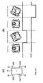
- Fig. 7A is a front view of a state before the inclination sensor operates;
- Fig. 7B is a schematic front view of the state before the inclination sensor operates;
- Fig. 7C is a schematic right side view of the state before the inclination sensor operates
- Fig. 7D is a schematic plan view of the state before the inclination sensor operates;
- Fig. 8A is a front view of a state after the inclination sensor operates;
- Fig. 8B is a schematic front view of the state after the inclination sensor operates;
- Fig. 8C is a schematic right side view of the state after the inclination sensor operates;
- Fig. 8D is a schematic plan view of the state after the inclination sensor operates;
- Fig. 9A is a front view of a state after the inclination sensor operates in a different direction;
- Fig. 9B is a schematic front view of the state after the inclination sensor operates in a different direction;
- Fig. 9C is a schematic right side view of the state after the inclination sensor operates in a different direction;
- Fig. 9D is a schematic plan view of the state after the inclination sensor operates in a different direction;
- Fig. 10 is a graph of an output state in the case in which a hall IC is used as magnetism detecting means; and
- Fig. 11 is a graph of an output state in a second embodiment using a hall element as the magnetism detecting means.
- Embodiment of the invention will be explained with reference to the accompanying drawings.
- An inclination sensor according to the first embodiment includes, as shown in Figs. 1 to 10, a
case 10, ahall IC 20 serving as magnetism detecting means, a pair ofpermanent magnets pendulum 30 assembled with a pair offerromagnetic bodies cover 40. Note that a size of an inclination sensor body according to this embodiment is 7mm wide, 7 mm high, and 2 mm thick. - As shown in Fig. 2, the
case 10 is a resin molded product having a substantially square box shape in front in which fourlead terminals shaft section 15 is projected in a lateral direction in a front center of thecase 10. A housing recessedportion 16, which houses ahall IC 20 described later, and a recessedportion 17 for positional regulation, which positionally regulates an operation of apendulum 30 described later, are provided in positions opposed to each other in a vertical direction across the turningshaft section 15. Connectingsections 11a to 14a of thelead terminals 11 to 14 are exposed at an opening edge of the housing recessedportion 16. As shown in Fig. 4, fitting recessedportions square magnets case 10. On the other hand, engaging projectedportions 19 are projected on outside surfaces of thecase 10 opposed to each other. - The
hall IC 20 has an external shape capable of housing thehall IC 20 in the housing recessedportion 16. Thehall IC 20 has a circular magnetic flux detecting area (not shown) is the center thereof.Bent VSS terminal 21,OUT2 terminal 22,VDD terminal 23, andOUT1 terminal 24 are projected in a lateral direction from both the outside surfaces as lead terminals. After being fit in the housing recessedportion 16 of thecase 10 and positioned, theterminals 21 to 24 are welded and electrically connected to connectingsections 11a to 14a of thelead terminals 11 to 14. Note that thehall IC 20 may be constituted by one hall element or may be constituted by two hall elements. - The
pendulum 30 consists of a weak magnetic substance or a diamagnetic substance having a high specific gravity. Thependulum 30 has abearing hole 31 that is axially supported by the turningshaft section 15 of thecase 10 to be capable of turning. In addition, lower ends of the pair offerromagnetic bodies fitting grooves 33 and 34 (see Fig. 4), which are provided on surfaces opposed to thecase 10, from a lateral direction. Theferromagnetic bodies magnets shaft section 15 of thecase 10 is inserted through the bearinghole 31 of thependulum 30 assembled with the pair offerromagnetic bodies pendulum 30 is supported to be capable of turning. - The
cover 40 has a front shape capable of covering a front surface of thecase 10. Anannular rib 41, which comes into abutment against and positionally regulates thependulum 30, is projected in the center of thecover 40. In thecover 40, engagingpawls 42 are extended at edges on both sides opposed to each other. On the other hand, positioningribs 43 are extended at the remaining edges on both sides opposed to each other. The engagingpawls 42 of thecover 40 are engaged with the engaging projectedportions 19 of thecase 10, whereby theannular rib 41 comes into abutment against the opening edge of the bearinghole 31 of thependulum 30 to prevent thependulum 30 from falling (Fig. 5). - Operations of the inclination sensor including the components described above will be explained.
- As shown in Fig. 7, when the
case 10 is not inclined, both theferromagnetic bodies hall IC 20. Therefore, magnetic fluxes of themagnets hall IC 20 to close a magnetic circuit (Fig. 7D). Therefore, an output of thehall IC 20 is always high (Fig. 10). - As shown in Fig. 8, when the case inclines clockwise and the
ferromagnetic body 36 approaches and overlaps thehall IC 20, magnetic fluxes emitted from themagnet 25 flow into themagnet 26 through theferromagnetic body 36 to close a magnetic circuit. Therefore, the magnetic fluxes flow in from a rear surface to a front surface of thehall IC 20 crossing thehall IC 20 to form magnetic flux components perpendicular to thehall IC 20. When the magnetic flux components exceed a predetermined threshold value, the output of thehall IC 20 changes from high to low (Fig. 10). - Subsequently, when the
case 10 returns to the original position, theferromagnetic body 36 separates from thehall IC 20, a magnetic circuit is closed only by themagnets hall IC 20. Therefore, the output of thehall IC 20 changes from low to high (Fig. 10). - Conversely, as shown in Fig. 9, when the
case 10 inclines counter clockwise and theferromagnetic body 35 approaches and overlaps thehall IC 20, magnetic fluxes emitted from themagnet 25 flow into themagnet 26 through theferromagnetic body 35 to close a magnetic circuit. Therefore, the magnetic fluxes flow in from the front surface to the rear surface of thehall IC 20 crossing thehall IC 20 to form magnetic flux components perpendicular to the front surface of thehall IC 20. When the magnetic flux components exceed the predetermined threshold value, the output of thehall IC 20 changes from high to low (Fig. 10). - Subsequently, when the
case 10 returns to the original position, theferromagnetic body 35 separates from thehall IC 20, a magnetic circuit is closed only by themagnets hall IC 20. Therefore, the output of thehall IC 20 changes from low to high (Fig. 10). - In a second embodiment, as shown in Fig. 11, a
hall element 25 is used as magnetism detecting means. In thehall element 25, anegative output terminal 21, anegative input terminal 22, apositive input terminal 23, and apositive output terminal 24 are projected from both outer sides thereof in a lateral direction as lead terminals. After being fit in the housing recessedportion 16 of thecase 10 and positioned, theterminals 21 to 24 are welded and electrically connected to the connectingsections 11a to 14a of thelead terminals 11 to 14. Note that the magnetism detecting means may be constituted by one hall element to detect inclination states in two directions through an external control circuit or may be constituted by two hall elements to detect inclination states in two directions. - According to this embodiment, an output voltage of the
hall element 25 changes linearly in position and negative areas according to an inclination angle of thecase 10. Thus, there is an advantage that it is possible not only to judge inclination directions of the inclination sensor from output voltage of onehole element 25 but also to detect inclination angles one after another. - In the invention, a hall IC for detecting inclination only in one direction may be used as the magnetism detecting means. Alternatively, inclinations in two directions may be detected by two hall ICs separately.
- In the explanations of the embodiments described above, the separate ferromagnetic bodies are assembled to the pendulum. However, the invention is not limited to this case. The pendulum and the ferromagnetic bodies may be integrally formed of an identical magnetic material. Consequently, there is an advantage that it is possible to obtain an inclination sensor with a small number of components and a small number of assembly man-hours.
- The inclination sensor according to the invention is not limited to detection of inclination of a digital camera, a video camera, and the like. The inclination sensor can also be mounted on electronic apparatuses such as a cellular phone and a portable music player.
Claims (4)
- An inclination sensor comprising: a case having a turning shaft section projected in a lateral direction on a front surface thereof; magnetism detecting means fixed on an upper side of the turning shaft section; a pair of magnets fixed in parallel to a rear surface of the case to be located on both sides of the magnetism detecting means; a pendulum axially supported by the turning shaft section to turn freely; and a pair of ferromagnetic bodies fixed on an inward surface of the pendulum, wherein
when the case inclines, one of the ferromagnetic bodies approaches the magnetism detecting means, a magnetic circuit is closed by the pair of magnets and one of the ferromagnetic bodies, and magnetic fluxes of the magnets pass over front and rear surfaces of the magnetism detecting means. - An inclination sensor according to claim 1, wherein the magnetism detecting means is a hall IC consisting of at least one hall element.
- An inclination sensor according to claim 1 or 2, wherein the pendulum and the ferromagnetic bodies are integrally formed of an identical magnetic material.
- An inclination sensor according to any one of claims 1 to 3, wherein a projected portion for positional regulation is provided on at least one of opposed surfaces of the case and the pendulum, and a recessed portion for positional regulation, in which the projected portion for positional regulation locks, is provided on the other opposed surface.
Applications Claiming Priority (1)
| Application Number | Priority Date | Filing Date | Title |
|---|---|---|---|
| JP2004275356A JP4033183B2 (en) | 2004-09-22 | 2004-09-22 | Tilt sensor |
Publications (2)
| Publication Number | Publication Date |
|---|---|
| EP1640689A2 true EP1640689A2 (en) | 2006-03-29 |
| EP1640689A3 EP1640689A3 (en) | 2011-10-05 |
Family
ID=35539411
Family Applications (1)
| Application Number | Title | Priority Date | Filing Date |
|---|---|---|---|
| EP05019337A Withdrawn EP1640689A3 (en) | 2004-09-22 | 2005-09-06 | Magnetic inclination sensor |
Country Status (4)
| Country | Link |
|---|---|
| US (1) | US7318283B2 (en) |
| EP (1) | EP1640689A3 (en) |
| JP (1) | JP4033183B2 (en) |
| CN (1) | CN100549621C (en) |
Cited By (1)
| Publication number | Priority date | Publication date | Assignee | Title |
|---|---|---|---|---|
| US7721968B2 (en) | 2003-10-31 | 2010-05-25 | Iota Wireless, Llc | Concurrent data entry for a portable device |
Families Citing this family (13)
| Publication number | Priority date | Publication date | Assignee | Title |
|---|---|---|---|---|
| KR20090007420A (en) * | 2006-04-11 | 2009-01-16 | 보아트 롱이어 인터내셔날 홀딩스, 인크. | Drill rod handler |
| US8186926B2 (en) * | 2006-04-11 | 2012-05-29 | Longyear Tm, Inc. | Drill rod handler |
| US7353615B1 (en) * | 2007-01-03 | 2008-04-08 | Shockwatch, Inc. | Anti-vibration tilt detector |
| US7956602B2 (en) | 2007-04-06 | 2011-06-07 | Sae Magnetics (H.K.) Ltd. | Tilt angle sensor and detection-target device comprising the same |
| US7856727B2 (en) * | 2008-10-21 | 2010-12-28 | Agatec | Independent position sensor and a system to determine the position of a tool on a works machine using position sensors |
| TW201043928A (en) * | 2009-06-12 | 2010-12-16 | Taiwan Misaki Electronics Co | Tilt detection sensor |
| JP5522534B2 (en) * | 2010-06-23 | 2014-06-18 | 宇部興産機械株式会社 | Method for measuring movable platen position of toggle type mold clamping device |
| CN103090849B (en) * | 2011-10-27 | 2016-01-27 | 现代摩比斯株式会社 | Detector for vehicle gradient |
| WO2014021999A1 (en) | 2012-08-01 | 2014-02-06 | Shockwatch, Inc. | Tilt indicator |
| CN108981664B (en) * | 2018-08-03 | 2020-09-11 | 北方工业大学 | Photoelectric closed-loop tilt angle sensor |
| CN110906851B (en) * | 2019-10-22 | 2021-07-23 | 上海海事大学 | Bridge crane swing angle and rope length detection device and detection method |
| EP4091147A4 (en) | 2020-01-14 | 2024-04-24 | Shockwatch, Inc. | Tilt indicator |
| CN116625314B (en) * | 2023-07-20 | 2023-10-20 | 青岛汇金通电力设备股份有限公司 | Wind power tower inclination angle measuring device |
Citations (2)
| Publication number | Priority date | Publication date | Assignee | Title |
|---|---|---|---|---|
| GB2167191A (en) * | 1984-11-16 | 1986-05-21 | David Louis Halsey Person | Hall-effect attitude sensors |
| EP0768513A2 (en) * | 1995-10-13 | 1997-04-16 | Robert Bosch Gmbh | Tilt sensor |
Family Cites Families (17)
| Publication number | Priority date | Publication date | Assignee | Title |
|---|---|---|---|---|
| US2572766A (en) * | 1945-01-25 | 1951-10-23 | Bendix Aviat Corp | Pendulum device |
| US3233235A (en) * | 1963-08-16 | 1966-02-01 | Wright Gilbert | Signaling level |
| GB2121961B (en) * | 1982-06-09 | 1985-10-02 | Jeco Kk | Angle change detector |
| GB2170006B (en) * | 1985-01-22 | 1988-01-13 | Penny & Giles Potentiometers L | Inclinometers |
| US4700479A (en) * | 1985-09-02 | 1987-10-20 | Honda Giken Kogyo Kabushiki Kaisha | Cant angle sensor assembly |
| US4811492A (en) * | 1986-08-29 | 1989-03-14 | Honda Giken Kogyo Kabushiki Kaisha | Cant angle sensor assembly |
| US5174035A (en) * | 1989-05-18 | 1992-12-29 | Shigemi Yamazaki | Attitude sensing apparatus |
| US5574442A (en) * | 1993-07-12 | 1996-11-12 | Murata Manufacturing Co., Ltd. | Inclination angle sensor |
| KR100377090B1 (en) * | 1997-12-09 | 2003-03-26 | 마쯔시다덴기산교 가부시키가이샤 | Inclination sensor |
| JP3673988B2 (en) | 1998-11-05 | 2005-07-20 | 東洋電装株式会社 | Tilt sensor |
| JP3659855B2 (en) * | 2000-02-25 | 2005-06-15 | 株式会社タイコーデバイス | Tilt sensor |
| JP2002372416A (en) * | 2001-04-09 | 2002-12-26 | Nagano Fujitsu Component Kk | Sensor unit |
| US6987460B2 (en) * | 2003-03-14 | 2006-01-17 | Pelco | Orientation device |
| JP2005257520A (en) * | 2004-03-12 | 2005-09-22 | Omron Corp | Inclination sensor |
| JP4365262B2 (en) * | 2004-04-23 | 2009-11-18 | 朝日電装株式会社 | Tilt sensor for boarding means |
| JP4465607B2 (en) * | 2004-12-27 | 2010-05-19 | 東洋電装株式会社 | Tilt sensor |
| US7325322B2 (en) * | 2005-02-01 | 2008-02-05 | Delphi Technologies, Inc. | Electric park brake inclinometer |
-
2004
- 2004-09-22 JP JP2004275356A patent/JP4033183B2/en not_active Expired - Fee Related
-
2005
- 2005-09-06 EP EP05019337A patent/EP1640689A3/en not_active Withdrawn
- 2005-09-16 US US11/228,819 patent/US7318283B2/en not_active Expired - Fee Related
- 2005-09-22 CN CNB2005101069471A patent/CN100549621C/en not_active Expired - Fee Related
Patent Citations (2)
| Publication number | Priority date | Publication date | Assignee | Title |
|---|---|---|---|---|
| GB2167191A (en) * | 1984-11-16 | 1986-05-21 | David Louis Halsey Person | Hall-effect attitude sensors |
| EP0768513A2 (en) * | 1995-10-13 | 1997-04-16 | Robert Bosch Gmbh | Tilt sensor |
Cited By (1)
| Publication number | Priority date | Publication date | Assignee | Title |
|---|---|---|---|---|
| US7721968B2 (en) | 2003-10-31 | 2010-05-25 | Iota Wireless, Llc | Concurrent data entry for a portable device |
Also Published As
| Publication number | Publication date |
|---|---|
| US20070251108A1 (en) | 2007-11-01 |
| US7318283B2 (en) | 2008-01-15 |
| EP1640689A3 (en) | 2011-10-05 |
| JP2006090796A (en) | 2006-04-06 |
| CN1752716A (en) | 2006-03-29 |
| CN100549621C (en) | 2009-10-14 |
| JP4033183B2 (en) | 2008-01-16 |
Similar Documents
| Publication | Publication Date | Title |
|---|---|---|
| US7318283B2 (en) | Inclination sensor | |
| US6922052B2 (en) | Measuring device for contactless detecting a ferromagnetic object | |
| US11378771B2 (en) | Optical element driving mechanism | |
| JP6827058B2 (en) | Current sensor | |
| JPH0979865A (en) | Magnetic detecting sensor | |
| US11506862B2 (en) | Optical element driving mechanism | |
| JP2006317389A (en) | Angle switch sensor | |
| US20080204002A1 (en) | Inclination sensor | |
| US20110036182A1 (en) | Rotary torque detecting device | |
| CN101655541B (en) | Magnetic sensor and magnetic sensor device | |
| JP2010153199A (en) | Multidirectional input unit | |
| WO2021020541A1 (en) | Rotation angle detection sensor | |
| US11682955B2 (en) | Optical element driving mechanism | |
| JP4618424B2 (en) | Tilt sensor | |
| JP2007179919A (en) | Rigid ball detection sensor | |
| JP2006012504A (en) | Non-contact switch, and position detecting device using the same | |
| JP2010271298A (en) | Angle sensor, and rotation angle detecting device using the same | |
| JP4360947B2 (en) | Tilt sensor | |
| JP2006164958A (en) | Crime prevention sensor | |
| JP2006177924A (en) | Displacement detector | |
| JP2014102181A (en) | Magnetic sensor | |
| US20090195242A1 (en) | Swing type switching device including magnet and magnetoresistive element | |
| JP4055561B2 (en) | Position detection device | |
| JP5666192B2 (en) | Current sensor | |
| JP2018036140A (en) | Magnetic sensor device |
Legal Events
| Date | Code | Title | Description |
|---|---|---|---|
| PUAI | Public reference made under article 153(3) epc to a published international application that has entered the european phase |
Free format text: ORIGINAL CODE: 0009012 |
|
| AK | Designated contracting states |
Kind code of ref document: A2 Designated state(s): AT BE BG CH CY CZ DE DK EE ES FI FR GB GR HU IE IS IT LI LT LU LV MC NL PL PT RO SE SI SK TR |
|
| AX | Request for extension of the european patent |
Extension state: AL BA HR MK YU |
|
| PUAL | Search report despatched |
Free format text: ORIGINAL CODE: 0009013 |
|
| AK | Designated contracting states |
Kind code of ref document: A3 Designated state(s): AT BE BG CH CY CZ DE DK EE ES FI FR GB GR HU IE IS IT LI LT LU LV MC NL PL PT RO SE SI SK TR |
|
| AX | Request for extension of the european patent |
Extension state: AL BA HR MK YU |
|
| RIC1 | Information provided on ipc code assigned before grant |
Ipc: G01R 33/07 20060101ALI20110831BHEP Ipc: G01C 9/12 20060101ALI20110831BHEP Ipc: G01C 9/06 20060101AFI20110831BHEP |
|
| 17P | Request for examination filed |
Effective date: 20120127 |
|
| 17Q | First examination report despatched |
Effective date: 20120425 |
|
| AKX | Designation fees paid |
Designated state(s): AT BE BG CH CY CZ DE DK EE ES FI FR GB GR HU IE IS IT LI LT LU LV MC NL PL PT RO SE SI SK TR |
|
| STAA | Information on the status of an ep patent application or granted ep patent |
Free format text: STATUS: THE APPLICATION IS DEEMED TO BE WITHDRAWN |
|
| 18D | Application deemed to be withdrawn |
Effective date: 20140108 |