EP1640687A1 - Multi-range capacitive distance sensor and method of oparating the same - Google Patents
Multi-range capacitive distance sensor and method of oparating the same Download PDFInfo
- Publication number
- EP1640687A1 EP1640687A1 EP05255982A EP05255982A EP1640687A1 EP 1640687 A1 EP1640687 A1 EP 1640687A1 EP 05255982 A EP05255982 A EP 05255982A EP 05255982 A EP05255982 A EP 05255982A EP 1640687 A1 EP1640687 A1 EP 1640687A1
- Authority
- EP
- European Patent Office
- Prior art keywords
- sensor
- conductive elements
- operable
- probe
- separation
- Prior art date
- Legal status (The legal status is an assumption and is not a legal conclusion. Google has not performed a legal analysis and makes no representation as to the accuracy of the status listed.)
- Granted
Links
Images


Classifications
-
- G—PHYSICS
- G01—MEASURING; TESTING
- G01D—MEASURING NOT SPECIALLY ADAPTED FOR A SPECIFIC VARIABLE; ARRANGEMENTS FOR MEASURING TWO OR MORE VARIABLES NOT COVERED IN A SINGLE OTHER SUBCLASS; TARIFF METERING APPARATUS; MEASURING OR TESTING NOT OTHERWISE PROVIDED FOR
- G01D5/00—Mechanical means for transferring the output of a sensing member; Means for converting the output of a sensing member to another variable where the form or nature of the sensing member does not constrain the means for converting; Transducers not specially adapted for a specific variable
- G01D5/12—Mechanical means for transferring the output of a sensing member; Means for converting the output of a sensing member to another variable where the form or nature of the sensing member does not constrain the means for converting; Transducers not specially adapted for a specific variable using electric or magnetic means
- G01D5/14—Mechanical means for transferring the output of a sensing member; Means for converting the output of a sensing member to another variable where the form or nature of the sensing member does not constrain the means for converting; Transducers not specially adapted for a specific variable using electric or magnetic means influencing the magnitude of a current or voltage
- G01D5/24—Mechanical means for transferring the output of a sensing member; Means for converting the output of a sensing member to another variable where the form or nature of the sensing member does not constrain the means for converting; Transducers not specially adapted for a specific variable using electric or magnetic means influencing the magnitude of a current or voltage by varying capacitance
- G01D5/241—Mechanical means for transferring the output of a sensing member; Means for converting the output of a sensing member to another variable where the form or nature of the sensing member does not constrain the means for converting; Transducers not specially adapted for a specific variable using electric or magnetic means influencing the magnitude of a current or voltage by varying capacitance by relative movement of capacitor electrodes
- G01D5/2417—Mechanical means for transferring the output of a sensing member; Means for converting the output of a sensing member to another variable where the form or nature of the sensing member does not constrain the means for converting; Transducers not specially adapted for a specific variable using electric or magnetic means influencing the magnitude of a current or voltage by varying capacitance by relative movement of capacitor electrodes by varying separation
-
- G—PHYSICS
- G01—MEASURING; TESTING
- G01B—MEASURING LENGTH, THICKNESS OR SIMILAR LINEAR DIMENSIONS; MEASURING ANGLES; MEASURING AREAS; MEASURING IRREGULARITIES OF SURFACES OR CONTOURS
- G01B7/00—Measuring arrangements characterised by the use of electric or magnetic techniques
- G01B7/14—Measuring arrangements characterised by the use of electric or magnetic techniques for measuring distance or clearance between spaced objects or spaced apertures
Definitions
- the invention relates generally to sensor systems and, more particularly, to a sensor system that is operable to adjust a physical characteristic of a sensor in response to an output of the sensor.
- a turbine has a turbine blade that is disposed adjacent to a shroud.
- the clearance between the turbine blade and the shroud varies depending on the temperature of the turbine blade. For example, the clearance between the shroud and the turbine blade is greatest when the turbine is cold and gradually decreases as the turbine heats up. It is desirable that a gap or clearance between the turbine blade and the shroud be maintained for safe and effective operation of the turbine.
- a sensor may be disposed within the turbine to measure the distance between the turbine blade and the shroud. The distance may be used to direct movement of the shroud to maintain the desired displacement between the shroud and the turbine blade.
- a capacitance probe is employed to measure the distance between two objects.
- the dimensions of the capacitance probe tip are selected to correspond to a single displacement distance between the two objects.
- Small probes are typically limited to small distance measurements, as a result of the signal to noise ratio.
- large probes are typically limited to large distance measurements because they provide poor resolution of the distance between the two objects for small distance measurements.
- conventional capacitance probes may be inaccurate at displacement distances other than the displacement distance for which the probe tip was designed.
- a sensor system comprising a sensor operable to provide an output signal representative of a sensed parameter.
- the sensor system also comprises a control system coupled to the sensor, wherein the control system is operable to change a physical characteristic of the sensor based on the output signal representative of the sensed parameter.
- a method of operating a sensor system comprises receiving an output signal representative of a sensed parameter via a sensor and controlling a physical characteristic of the sensor based on the output signal representative of the sensed parameter.
- the sensor system 10 comprises a probe 12 operable to provide an output signal representative of a sensed parameter.
- the probe 12 comprises a first conducting element 14, a second conductive element 16, and a third conductive element 18.
- the illustrated embodiment of the sensor system 10 comprises a probe control system 20, a first switch 22, a second switch 24, and a third switch 26 for selectively coupling the conducting elements 14, 16 and 18 to the probe control system 20
- the probe control system 20 is operable to optimize the configuration of the probe 12 based on the output of the probe 12 by selectively coupling the conductive elements 14, 16, and 18 together.
- the conducting elements 14, 16 and 18 are also coupled to a separation control system 28 that is operable to control the separation between the probe 12 and a target that will also be described in detail below.
- An additional conductive element 30 is provided to act as a return path and to shield the probe 12 from noise and interference. However, a greater number of conductive elements may be coupled to the conductive element 30 for shielding the probe 12.
- the conductive elements 14, 16 and 18 are coupled to the separation control system 28 and the probe control system 20 via cables 32 and 34, respectively.
- the probe 12 is a capacitance probe that senses the capacitance between the probe 12 and an object 36.
- the capacitance between two objects is a function of the overlap surface area (A) and the separation (S) 38 between the probe 12 and the object 36.
- the overlap surface area (A) is the area of the probe 12 because the area of the object 36 is greater than the area of the probe 12.
- the separation control system 28 is operable to control the separation (S) 38 between the probe 12 and the object 36 based on a signal representative of the capacitance (C) received from the probe 12.
- the separation control system 28 is operable to establish the separation (S) 38 between the probe 12 and the object 36 using equation (2) above and data programmed into the separation control system 28.
- the separation control system 28 may simply use the capacitance (C) to control the separation (S) 38 between the probe 12 and the object 36.
- the capacitance (C) and/or the separation (S) are compared to a desired value of the capacitance and/or the separation (S).
- the separation control system 28 is operable to direct the displacement of the object 36 to maintain the desired capacitance (C) or separation (S).
- the probe control system 20 is operable to optimize the area (A) of the probe 12 to correspond to the actual separation (S) 38 or capacitance (C).
- the probe control system. 20 decreases the area (A) of the probe 12 as the separation (S) 38 decreases and increases the area (A) of the probe 12 as the separation (S) 38 increases.
- the probe control system 20 controls the area (A) of the probe 12 by selectively closing the switches 22, 24 and 26, thereby controlling the specific conductive elements 14, 16 and 18 that are coupled to the separation control system 28. For example, if the separation (S) 38 between the probe 12 and the object 36 is small, the probe control system 20 may couple a single conductive element 18, other than the return path 30, to the separation control system 28 by closing switch 26 and opening switches 22 and 24. Alternatively, as the separation (S) 38 between the probe 12 and the object 36 increases, the probe control system 20 may operatively couple conductive elements 14 and 16 to the separation control system 28 by closing switches 22 and 24.
- the probe control system 20 comprises an interface 40 for facilitating control of the switches 22, 24, and 26.
- the probe control system 20 also comprises a processor 42 for processing the capacitance signal from the probe 12 and directing the interface to selectively open and close the switches 22, 24, and 26.
- the probe control system 20 also includes a memory circuitry 44 for storing pre-defined programs, internal references, and other information for controlling the selectively coupling of the conductive elements 14, 16 and 18.
- switches 22, 24 and 26 are employed for coupling the conductive elements 14, 16 and 18 to the probe 12.
- the switches 22, 24 and 26 comprise solid-state switches.
- the switches 22, 24 and 26 may comprise mechanical relays.
- the switches 22, 24 and 26 may comprise radio frequency micro-electromechanical systems switches. It should be noted that, coupling of additional conductive elements 16 and 18 via the switches 24 and 26 enhances a range of measurement of the probe 12.
- when the conductive elements that are not being utilized to be coupled together may be coupled to the conductive element 30 to provide additional shielding.
- the unused conductive elements may be held at a pre-determined potential to reduce interference in the measurement.
- a first probe 50 is provided in which the conductive elements are conductive shafts.
- the conductive shafts comprise a center conductor 52, a first group of conductive elements 54, and a second group of conductive elements 56 that are arranged in a pre-determined pattern.
- the center conductive element 52 may be coupled to the probe 12 for all ranges of measurement by the probe 12.
- the first group of conductive elements 54 may be coupled to the center conductor 52 to increase the area (A). If additional area is need, the second group of conductive elements 56 may be coupled to the center conductor 52 and to the first group of conductive elements 54.
- other configurations may be used.
- An outer conductive element 58 is disposed around the conductive elements 52, 54, and 56 to act as a return path and to shield the conductive elements 52, 54, and 56 from electrical noise and interference. In an alternative embodiment, any unused conductive elements may be coupled to the outer conductive element 58.
- FIG 3 illustrates another exemplary embodiment of a probe 60.
- the probe 60 comprises a center conductive element 62 and cylindrical conductive elements 64 and 68 surrounding the center conductive element 62 in an annular pattern.
- An outer conductive element 68 is disposed around the conductive elements 62, 64 and 66 to reduce the effect of any electrical noise and interference on the measurement of capacitance and/or separation.
- the probe 60 may have a lesser or greater number of conductive elements based upon a desired range of measurement.
- the conductive elements 64 and 68 may be selectively coupled to the center conductive element 62 for enhancing the resolution of the probe 60.
- an exemplary method 70 of operating the sensor system 10 of Figure 1 is illustrated.
- an initial configuration of sensor elements of a sensor is selected for measuring a separation of an external object from the sensor, as represented by block 72.
- the measurement data from the sensor is used to establish a capacitance (C) between the sensor and the external object.
- the separation (S) between the sensor and the external object is established based upon the capacitance (C) sensed by the sensor.
- the measured capacitance (C) or separation (S) is compared to a desired range of values of capacitance (C) and separation (S), as represented by block 78.
- the configuration of the sensor is modified, as represented by block 80.
- the configuration of the sensor may be modified by coupling more conductive elements to the initial configuration of the sensor.
- the configuration of the sensor may be changed by removing conductive elements from the initial configuration of the sensor.
- the system is operated by employing the modified configuration to establish the desired separation.
- the method steps from 74-82 may be iterated to achieve the desired separation between the sensor and the external object at different points in time.
- Figure 5 illustrates another exemplary method 84 of operating the sensor system 10 of Figure 1.
- separation (S) and/or capacitance (C) are established for each of a plurality of sensor element configurations, as represented by block 86.
- the separation (S) and/or capacitance (C) as measured by the plurality of sensor element configurations are analyzed to identify the optimum separation (S) and/or capacitance (C) setting, as represented by block 88.
- the analysis of the measured separation (S) and/or capacitance (C) may be performed in real time. Alternatively, the analysis of the measured separation (S) and/or capacitance (C) may be performed off-line.
- a desired clearance or separation (S) is estimated based upon the measured separation (S) and/or capacitance (C) at the optimum setting.
- the measurement technique described hereinabove provides an accurate measurement of the clearance between a stationary object and an adjacent moving part.
- the various aspects of the method described hereinabove have utility in applications where clearance measurements over a wide range of distance are required.
- the technique described above may be used for measuring the clearance between a rotating component and a stationary component in an aircraft engine.
- the method described here may be advantageous for measurements over a wide range of distances by selectively coupling the conductive elements of the sensor to tailor the area of the sensor to measure the distance between the objects.
Landscapes
- Physics & Mathematics (AREA)
- General Physics & Mathematics (AREA)
- Engineering & Computer Science (AREA)
- Power Engineering (AREA)
- Measurement Of Length, Angles, Or The Like Using Electric Or Magnetic Means (AREA)
- Electronic Switches (AREA)
Abstract
Description
- The invention relates generally to sensor systems and, more particularly, to a sensor system that is operable to adjust a physical characteristic of a sensor in response to an output of the sensor.
- Various types of sensors have been used to measure the distance between two objects. In addition, these sensors have been used in various applications. For example, a turbine has a turbine blade that is disposed adjacent to a shroud. The clearance between the turbine blade and the shroud varies depending on the temperature of the turbine blade. For example, the clearance between the shroud and the turbine blade is greatest when the turbine is cold and gradually decreases as the turbine heats up. It is desirable that a gap or clearance between the turbine blade and the shroud be maintained for safe and effective operation of the turbine. A sensor may be disposed within the turbine to measure the distance between the turbine blade and the shroud. The distance may be used to direct movement of the shroud to maintain the desired displacement between the shroud and the turbine blade.
- In certain applications, a capacitance probe is employed to measure the distance between two objects. Conventionally, the dimensions of the capacitance probe tip are selected to correspond to a single displacement distance between the two objects. Small probes are typically limited to small distance measurements, as a result of the signal to noise ratio. Similarly, large probes are typically limited to large distance measurements because they provide poor resolution of the distance between the two objects for small distance measurements. As a result, conventional capacitance probes may be inaccurate at displacement distances other than the displacement distance for which the probe tip was designed.
- Accordingly, there is a need to provide a sensor system that would accurately measure the clearance between two objects that are displaced relative to each other over an entire range of displacement.
- Briefly, in accordance with one aspect of the present invention a sensor system is provided. The sensor system comprises a sensor operable to provide an output signal representative of a sensed parameter. The sensor system also comprises a control system coupled to the sensor, wherein the control system is operable to change a physical characteristic of the sensor based on the output signal representative of the sensed parameter.
- In accordance with another aspect of the present invention a method of operating a sensor system is provided. The method comprises receiving an output signal representative of a sensed parameter via a sensor and controlling a physical characteristic of the sensor based on the output signal representative of the sensed parameter.
- These and other features, aspects, and advantages of the present invention will become better understood when the following detailed description is read with reference to the accompanying drawings in which like characters represent like parts throughout the drawings, wherein:
- Figure 1 is a diagrammatical representation of a sensor system for clearance measurement in a rotating machine, in accordance with an exemplary embodiment of the present technique;
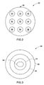
- Figure 2 is a diagrammatical representation of a sensor with a patterned array of sensor elements, in accordance with an exemplary embodiment of the present technique;
- Figure 3 is a diagrammatical representation of a sensor with an annular array of sensor elements, in accordance with an exemplary embodiment of the present technique;
- Figure 4 is a flow chart illustrating a method of operating the sensor system of Figure 1 in accordance with an exemplary embodiment of the present technique; and
- Figure 5 is a flow chart illustrating a method of operating the sensor system of Figure 1 in accordance with an exemplary embodiment of the present technique.
- Referring now to Figure 1, a sensor system is provided, and represented generally by
reference numeral 10. Thesensor system 10 comprises aprobe 12 operable to provide an output signal representative of a sensed parameter. Theprobe 12 comprises a firstconducting element 14, a secondconductive element 16, and a thirdconductive element 18. However, a lesser or greater number of conductive elements may be used in thesensor system 10. In addition, the illustrated embodiment of thesensor system 10 comprises aprobe control system 20, afirst switch 22, asecond switch 24, and athird switch 26 for selectively coupling the conductingelements probe control system 20 As described in greater detail below, theprobe control system 20 is operable to optimize the configuration of theprobe 12 based on the output of theprobe 12 by selectively coupling theconductive elements elements separation control system 28 that is operable to control the separation between theprobe 12 and a target that will also be described in detail below. An additionalconductive element 30 is provided to act as a return path and to shield theprobe 12 from noise and interference. However, a greater number of conductive elements may be coupled to theconductive element 30 for shielding theprobe 12. Further, theconductive elements separation control system 28 and theprobe control system 20 viacables - In the illustrated embodiment, the
probe 12 is a capacitance probe that senses the capacitance between theprobe 12 and anobject 36. The capacitance between two objects is a function of the overlap surface area (A) and the separation (S) 38 between theprobe 12 and theobject 36. In thesensor system 10, the overlap surface area (A) is the area of theprobe 12 because the area of theobject 36 is greater than the area of theprobe 12. The capacitance between two parallel plates is given by the following equation:
Where: C is the capacitance;
ε is the permittivity of a medium between the parallel plates;
A is the overlap area between the parallel plates; and
S is separation of the parallel plates. - By sensing the capacitance (C), the
probe 12 enables the separation (S) 38 between theprobe 12 and theobject 36 to be established. By manipulating equation (1) above, the following equation relates the separation (S) to the capacitance (C).
- As discussed in more detail below, the
separation control system 28 is operable to control the separation (S) 38 between theprobe 12 and theobject 36 based on a signal representative of the capacitance (C) received from theprobe 12. In this embodiment, theseparation control system 28 is operable to establish the separation (S) 38 between theprobe 12 and theobject 36 using equation (2) above and data programmed into theseparation control system 28. However, theseparation control system 28 may simply use the capacitance (C) to control the separation (S) 38 between theprobe 12 and theobject 36. The capacitance (C) and/or the separation (S) are compared to a desired value of the capacitance and/or the separation (S). In this embodiment, theseparation control system 28 is operable to direct the displacement of theobject 36 to maintain the desired capacitance (C) or separation (S). - The
probe control system 20 is operable to optimize the area (A) of theprobe 12 to correspond to the actual separation (S) 38 or capacitance (C). The probe control system. 20 decreases the area (A) of theprobe 12 as the separation (S) 38 decreases and increases the area (A) of theprobe 12 as the separation (S) 38 increases. Theprobe control system 20 controls the area (A) of theprobe 12 by selectively closing theswitches conductive elements separation control system 28. For example, if the separation (S) 38 between theprobe 12 and theobject 36 is small, theprobe control system 20 may couple a singleconductive element 18, other than thereturn path 30, to theseparation control system 28 byclosing switch 26 andopening switches probe 12 and theobject 36 increases, theprobe control system 20 may operatively coupleconductive elements separation control system 28 byclosing switches - In the illustrated embodiment, the
probe control system 20 comprises aninterface 40 for facilitating control of theswitches probe control system 20 also comprises aprocessor 42 for processing the capacitance signal from theprobe 12 and directing the interface to selectively open and close theswitches probe control system 20 also includes amemory circuitry 44 for storing pre-defined programs, internal references, and other information for controlling the selectively coupling of theconductive elements - As described above,
switches conductive elements probe 12. In one embodiment, theswitches switches switches conductive elements switches probe 12. In another embodiment, when the conductive elements that are not being utilized to be coupled together may be coupled to theconductive element 30 to provide additional shielding. In another embodiment, the unused conductive elements may be held at a pre-determined potential to reduce interference in the measurement. - Referring generally to Figures 2 and 3, various types and configurations of conductive elements that may be implemented for the sensor system of Figure 1 are provided. As illustrated in Figure 2, a
first probe 50 is provided in which the conductive elements are conductive shafts. The conductive shafts comprise acenter conductor 52, a first group ofconductive elements 54, and a second group ofconductive elements 56 that are arranged in a pre-determined pattern. The centerconductive element 52 may be coupled to theprobe 12 for all ranges of measurement by theprobe 12. The first group ofconductive elements 54 may be coupled to thecenter conductor 52 to increase the area (A). If additional area is need, the second group ofconductive elements 56 may be coupled to thecenter conductor 52 and to the first group ofconductive elements 54. However, other configurations may be used. An outerconductive element 58 is disposed around theconductive elements conductive elements conductive element 58. - Figure 3 illustrates another exemplary embodiment of a
probe 60. Theprobe 60 comprises a centerconductive element 62 and cylindricalconductive elements conductive element 62 in an annular pattern. An outerconductive element 68 is disposed around theconductive elements - Again, the
probe 60 may have a lesser or greater number of conductive elements based upon a desired range of measurement. Moreover, theconductive elements conductive element 62 for enhancing the resolution of theprobe 60. - Referring generally to Figure 4, an
exemplary method 70 of operating thesensor system 10 of Figure 1 is illustrated. Initially, an initial configuration of sensor elements of a sensor is selected for measuring a separation of an external object from the sensor, as represented byblock 72. Next, atblock 74 the measurement data from the sensor is used to establish a capacitance (C) between the sensor and the external object. As represented byblock 76, the separation (S) between the sensor and the external object is established based upon the capacitance (C) sensed by the sensor. Next, the measured capacitance (C) or separation (S) is compared to a desired range of values of capacitance (C) and separation (S), as represented byblock 78. - If the measured capacitance (C) or separation (S) is outside the desired range of capacitance (C) and/or separation (S) then the configuration of the sensor is modified, as represented by
block 80. The configuration of the sensor may be modified by coupling more conductive elements to the initial configuration of the sensor. Alternatively, the configuration of the sensor may be changed by removing conductive elements from the initial configuration of the sensor. Finally, as represented by block 82, the system is operated by employing the modified configuration to establish the desired separation. As will be appreciated by those skilled in the art, the method steps from 74-82 may be iterated to achieve the desired separation between the sensor and the external object at different points in time. - Figure 5 illustrates another
exemplary method 84 of operating thesensor system 10 of Figure 1. In the illustrated method, separation (S) and/or capacitance (C) are established for each of a plurality of sensor element configurations, as represented byblock 86. Next, the separation (S) and/or capacitance (C) as measured by the plurality of sensor element configurations are analyzed to identify the optimum separation (S) and/or capacitance (C) setting, as represented byblock 88. The analysis of the measured separation (S) and/or capacitance (C) may be performed in real time. Alternatively, the analysis of the measured separation (S) and/or capacitance (C) may be performed off-line. Subsequently, as represented atblock 90, a desired clearance or separation (S) is estimated based upon the measured separation (S) and/or capacitance (C) at the optimum setting. - The measurement technique described hereinabove provides an accurate measurement of the clearance between a stationary object and an adjacent moving part. The various aspects of the method described hereinabove have utility in applications where clearance measurements over a wide range of distance are required. For example, the technique described above may be used for measuring the clearance between a rotating component and a stationary component in an aircraft engine. As noted above, the method described here may be advantageous for measurements over a wide range of distances by selectively coupling the conductive elements of the sensor to tailor the area of the sensor to measure the distance between the objects.
Claims (10)
- A sensor system (10), comprising:a sensor (12) operable to provide an output signal representative of a sensed parameter; anda control system (20) coupled to the sensor (12), wherein the control system (20) is operable to change a physical characteristic of the sensor (12) based on the output signal representative of the sensed parameter.
- The system of claim 1, wherein the sensor (12) comprises a plurality of conductive elements (14).
- The system of claim 2, wherein at least one of the plurality of conductive elements (30) is operable to shield the sensor (12) from noise and interference.
- The system of claim 2, further comprising a plurality of switches (22) operable to selectively couple each of the plurality of conductive elements (14) to an output of the sensor (12).
- A sensor system (10), comprising:a sensor (12) operable to provide an output signal representative of a sensed parameter, wherein the sensor (12) comprises a plurality of conductive elements (14) and a plurality of switches (22) operable to selectively couple each of the plurality of conductive elements (14) to an output of the sensor (12); anda control system (20) operable to control each of the plurality of switches (22) to selectively couple each of the plurality of conductive elements (14) to the output of the sensor (12).
- A sensor system (10), comprising:a sensor (12) operable to provide an output signal representative of a distance between a sensing element (14) of the sensor (12) and an external object (36), wherein the sensor system (10) is operable to automatically change an area of the sensing element (14) based on the output signal representative of the distance between the sensing element (14) and the external object (36).
- A multi-range sensor (12) comprising:a plurality of conductive elements (14) operable to sense a parameter; anda plurality of switches (22) operable to selectively couple each of the plurality of conductive elements (14) to an output of the sensor (12).
- A method of operating a sensor system, comprising:receiving an output signal representative of a sensed parameter via a sensor; andcontrolling a physical characteristic of the sensor based on the output signal representative of the sensed parameter.
- A method of operating a sensor system, comprising:receiving an output signal representative of a sensed parameter via a sensor; andselectively coupling a plurality of conductive elements to an output of the sensor based on the output signal representative of the sensed parameter.
- A method of operating a sensor system, comprising:receiving a plurality of output signals representative of a sensed parameter via a plurality of configurations of a sensor;analyzing the plurality of output signals representative of the sensed parameter; andselecting a desired configuration of the sensor to measure a desired range of the sensed parameter.
Applications Claiming Priority (1)
| Application Number | Priority Date | Filing Date | Title |
|---|---|---|---|
| US10/951,562 US7332915B2 (en) | 2004-09-28 | 2004-09-28 | Sensor system and method of operating the same |
Publications (2)
| Publication Number | Publication Date |
|---|---|
| EP1640687A1 true EP1640687A1 (en) | 2006-03-29 |
| EP1640687B1 EP1640687B1 (en) | 2008-01-09 |
Family
ID=35355727
Family Applications (1)
| Application Number | Title | Priority Date | Filing Date |
|---|---|---|---|
| EP05255982A Expired - Lifetime EP1640687B1 (en) | 2004-09-28 | 2005-09-26 | An engine with a multi-range capacitive distance sensor |
Country Status (6)
| Country | Link |
|---|---|
| US (1) | US7332915B2 (en) |
| EP (1) | EP1640687B1 (en) |
| JP (1) | JP2006098403A (en) |
| CA (1) | CA2519527C (en) |
| DE (1) | DE602005004217T2 (en) |
| RU (1) | RU2392651C2 (en) |
Cited By (3)
| Publication number | Priority date | Publication date | Assignee | Title |
|---|---|---|---|---|
| EP1795861A1 (en) * | 2005-12-06 | 2007-06-13 | General Electric Company | Multi-range clearance measurement system and method of operation |
| EP1840499A1 (en) * | 2006-03-30 | 2007-10-03 | General Electric Company | Multi tip clearance measurement system and method of operation |
| WO2009047073A1 (en) * | 2007-10-05 | 2009-04-16 | Robert Bosch Gmbh | Sensor device for capacitive distance determination |
Families Citing this family (18)
| Publication number | Priority date | Publication date | Assignee | Title |
|---|---|---|---|---|
| US7466143B2 (en) * | 2005-09-16 | 2008-12-16 | General Electric Company | Clearance measurement systems and methods of operation |
| US8615374B1 (en) | 2006-06-09 | 2013-12-24 | Rockwell Automation Technologies, Inc. | Modular, configurable, intelligent sensor system |
| US7404331B2 (en) * | 2006-09-27 | 2008-07-29 | General Electric Company | Sensor assembly, transformers and methods of manufacture |
| US7605595B2 (en) * | 2006-09-29 | 2009-10-20 | General Electric Company | System for clearance measurement and method of operating the same |
| US8177474B2 (en) * | 2007-06-26 | 2012-05-15 | General Electric Company | System and method for turbine engine clearance control with rub detection |
| US7994800B2 (en) * | 2008-03-25 | 2011-08-09 | General Electric Company | Systems and methods for online phase calibration |
| US7852092B2 (en) * | 2008-03-25 | 2010-12-14 | General Electric Company | Systems for inspection of shrouds |
| US8272246B2 (en) * | 2008-09-30 | 2012-09-25 | General Electric Company | Electronic self-calibration for sensor clearance |
| KR20110089858A (en) * | 2008-10-31 | 2011-08-09 | 가부시키가이샤후지쿠라 | Capacitive Sensor |
| US8022715B2 (en) * | 2009-01-27 | 2011-09-20 | General Electric Company | Automated sensor specific calibration through sensor parameter download |
| JP5391411B2 (en) * | 2009-03-31 | 2014-01-15 | 株式会社フジクラ | Obstacle detection device for vehicle and airbag deployment control device for pedestrian protection |
| JP5607335B2 (en) * | 2009-10-19 | 2014-10-15 | アルプス電気株式会社 | Capacitive proximity sensor device, capacitive motion detection device, and input device using them |
| US8876460B2 (en) | 2011-08-11 | 2014-11-04 | General Electric Company | Method and apparatus for measuring turbine shell clearance |
| US8970228B2 (en) | 2012-05-31 | 2015-03-03 | General Electric Company | Rotational clearance measurement system and method of operation |
| US9417048B2 (en) | 2012-10-31 | 2016-08-16 | General Electric Company | Capacitive sensor device and method of manufacture |
| US9476318B2 (en) * | 2013-09-03 | 2016-10-25 | General Electric Company | Systems and methods to monitor a rotating component |
| US9587511B2 (en) | 2013-12-13 | 2017-03-07 | General Electric Company | Turbomachine cold clearance adjustment |
| CN113267343B (en) * | 2021-04-26 | 2024-06-14 | 中国联合重型燃气轮机技术有限公司 | Gas turbine test equipment |
Citations (5)
| Publication number | Priority date | Publication date | Assignee | Title |
|---|---|---|---|---|
| SU964437A2 (en) * | 1976-07-19 | 1982-10-07 | Институт Электродинамики Ан Усср | Capacitive transformer bridge for measuring displacements |
| DE4119244A1 (en) * | 1991-06-11 | 1992-12-17 | Weidmueller Interface | Capacitive sensor arrangement for measuring tool workpiece separation - contains sensor head with several electrodes on single or parallel, straight or circular lines |
| US6401541B1 (en) * | 1999-11-03 | 2002-06-11 | Kulite Semiconductor Products, Inc. | Multiple pressure sensing system |
| US20030011378A1 (en) * | 2001-07-11 | 2003-01-16 | Seiichiro Ishio | Capacitive sensor apparatus |
| JP2005134131A (en) * | 2003-10-28 | 2005-05-26 | Oki Electric Ind Co Ltd | Capacitance type distance measuring instrument |
Family Cites Families (22)
| Publication number | Priority date | Publication date | Assignee | Title |
|---|---|---|---|---|
| JPS526295Y2 (en) * | 1972-08-23 | 1977-02-09 | ||
| JPS5759101A (en) * | 1980-09-26 | 1982-04-09 | Hiromi Ogasawara | Noncontacting infinitesimal displacement gauge |
| JPS5914007U (en) * | 1982-07-20 | 1984-01-27 | イ−グル工業株式会社 | surface roughness meter |
| JPS6280502A (en) * | 1985-10-03 | 1987-04-14 | Stanley Electric Co Ltd | Capacitive proximity detection device |
| SU1557546A1 (en) * | 1988-06-06 | 1990-04-15 | Ленинградский Институт Водного Транспорта | Apparatus for determining condition of technical object |
| SU1684691A1 (en) * | 1989-05-03 | 1991-10-15 | Институт Прикладной Физики Ан Бсср | Method of measuring electric parameters of sensor |
| US5166626A (en) | 1990-05-29 | 1992-11-24 | General Electric Company | Electrical capacitance clearanceometer |
| US5119036A (en) | 1990-05-29 | 1992-06-02 | General Electric Company | Electrical capacitance clearanceometer |
| US5101165A (en) * | 1990-05-29 | 1992-03-31 | General Electric Company | Electrical capacitance clearanceometer |
| FR2712690B1 (en) * | 1993-11-17 | 1995-12-15 | Snecma | Device for performing the dynamic measurement of the distance between the facing faces of the rotor and the stator of a rotating machine. |
| JPH09203681A (en) * | 1996-01-29 | 1997-08-05 | Fuji Electric Co Ltd | Pressure detector |
| JP3602259B2 (en) * | 1996-05-02 | 2004-12-15 | 本田技研工業株式会社 | Multi-beam radar equipment |
| JP3732919B2 (en) * | 1996-12-19 | 2006-01-11 | トヨタ自動車株式会社 | Capacitive angle detector |
| JP3447946B2 (en) * | 1998-03-11 | 2003-09-16 | 三菱電機株式会社 | Radar equipment |
| JP4365908B2 (en) * | 1998-09-04 | 2009-11-18 | キヤノン株式会社 | Surface position detection apparatus, exposure apparatus, and device manufacturing method |
| JP4198306B2 (en) * | 1999-07-22 | 2008-12-17 | 東京エレクトロン株式会社 | Capacitive sensor, semiconductor manufacturing apparatus, and liquid crystal display element manufacturing apparatus |
| US6441623B1 (en) * | 1999-07-29 | 2002-08-27 | Ab Automotive Electronics Ltd. | Capacitive proximity sensor for automotive use |
| US6593755B1 (en) * | 2000-07-31 | 2003-07-15 | Banner Engineering Corporation | Method and apparatus for detection sensor shielding |
| JP2003021566A (en) * | 2001-07-10 | 2003-01-24 | Teijin Seiki Co Ltd | Silicon diaphragm type vacuum pressure sensor device and pressure measuring method using the device |
| US6744264B2 (en) * | 2002-04-25 | 2004-06-01 | Motorola, Inc. | Testing circuit and method for MEMS sensor packaged with an integrated circuit |
| US6774642B2 (en) * | 2002-08-27 | 2004-08-10 | Delphi Technologies, Inc. | Capacitive angular position sensor |
| JP3858865B2 (en) * | 2003-08-29 | 2006-12-20 | セイコーエプソン株式会社 | Capacitance detection device |
-
2004
- 2004-09-28 US US10/951,562 patent/US7332915B2/en not_active Expired - Lifetime
-
2005
- 2005-09-15 CA CA2519527A patent/CA2519527C/en not_active Expired - Fee Related
- 2005-09-26 DE DE602005004217T patent/DE602005004217T2/en active Active
- 2005-09-26 EP EP05255982A patent/EP1640687B1/en not_active Expired - Lifetime
- 2005-09-27 RU RU2005130123/09A patent/RU2392651C2/en not_active IP Right Cessation
- 2005-09-27 JP JP2005279269A patent/JP2006098403A/en active Pending
Patent Citations (5)
| Publication number | Priority date | Publication date | Assignee | Title |
|---|---|---|---|---|
| SU964437A2 (en) * | 1976-07-19 | 1982-10-07 | Институт Электродинамики Ан Усср | Capacitive transformer bridge for measuring displacements |
| DE4119244A1 (en) * | 1991-06-11 | 1992-12-17 | Weidmueller Interface | Capacitive sensor arrangement for measuring tool workpiece separation - contains sensor head with several electrodes on single or parallel, straight or circular lines |
| US6401541B1 (en) * | 1999-11-03 | 2002-06-11 | Kulite Semiconductor Products, Inc. | Multiple pressure sensing system |
| US20030011378A1 (en) * | 2001-07-11 | 2003-01-16 | Seiichiro Ishio | Capacitive sensor apparatus |
| JP2005134131A (en) * | 2003-10-28 | 2005-05-26 | Oki Electric Ind Co Ltd | Capacitance type distance measuring instrument |
Non-Patent Citations (1)
| Title |
|---|
| PATENT ABSTRACTS OF JAPAN vol. 2003, no. 12 5 December 2003 (2003-12-05) * |
Cited By (5)
| Publication number | Priority date | Publication date | Assignee | Title |
|---|---|---|---|---|
| EP1795861A1 (en) * | 2005-12-06 | 2007-06-13 | General Electric Company | Multi-range clearance measurement system and method of operation |
| JP2007155734A (en) * | 2005-12-06 | 2007-06-21 | General Electric Co <Ge> | Multi-range gap measurement system and method of operating the same |
| EP1840499A1 (en) * | 2006-03-30 | 2007-10-03 | General Electric Company | Multi tip clearance measurement system and method of operation |
| WO2009047073A1 (en) * | 2007-10-05 | 2009-04-16 | Robert Bosch Gmbh | Sensor device for capacitive distance determination |
| US8659407B2 (en) | 2007-10-05 | 2014-02-25 | Robert Bosch Gmbh | Sensor device for capacitively ascertaining distance |
Also Published As
| Publication number | Publication date |
|---|---|
| US20060066318A1 (en) | 2006-03-30 |
| DE602005004217D1 (en) | 2008-02-21 |
| RU2005130123A (en) | 2007-04-10 |
| CA2519527A1 (en) | 2006-03-28 |
| EP1640687B1 (en) | 2008-01-09 |
| JP2006098403A (en) | 2006-04-13 |
| DE602005004217T2 (en) | 2009-01-02 |
| CA2519527C (en) | 2014-03-04 |
| US7332915B2 (en) | 2008-02-19 |
| RU2392651C2 (en) | 2010-06-20 |
Similar Documents
| Publication | Publication Date | Title |
|---|---|---|
| EP1640687B1 (en) | An engine with a multi-range capacitive distance sensor | |
| US5586042A (en) | Apparatus and methods for measuring and detecting variations in the value of a capacitor | |
| US7722310B2 (en) | System and method for measuring clearance between two objects | |
| CN100447581C (en) | Method and hand-held measuring device for measuring the position of a target enclosed in a medium | |
| EP2351992B1 (en) | Method and assembly for contactless measurement of physical parameters on mobile parts of electric machines | |
| CA2223984C (en) | Clearance measurement system | |
| CN106092376B (en) | A kind of wireless temperature measurement means for correcting and method | |
| CA2293118A1 (en) | Bolometric fingerprint sensor | |
| EP2922205B1 (en) | Position sensing device and method using self-capacitance | |
| US7180305B2 (en) | Sensor systems and methods of operation | |
| CN111289600B (en) | Imaging device and method based on electrostatic sensor array | |
| Li et al. | A microcontroller-based self-calibration technique for a smart capacitive angular-position sensor | |
| Mandel et al. | Dielectric ring resonators as chipless temperature sensors for wireless machine tool monitoring | |
| CN107943642B (en) | Performance test method of capacitive touch sensing device | |
| JP6498709B2 (en) | Detection apparatus and substance detection method | |
| US20190310736A1 (en) | Evaluation of touch screen display capacitance using a touch screen controller | |
| EP3218731B1 (en) | Pivot supporting structure and circuit breaker | |
| JP2007278820A (en) | Electric field probe and system for measuring electric field | |
| EP2793018A1 (en) | Thermal conductivity based gas sensor | |
| US10634515B2 (en) | Apparatus and method for the position determination of a cylinder piston | |
| US4363073A (en) | Variable capacitor transducer | |
| CN111896610A (en) | Method and device for improving metal material gap detection precision and detection range | |
| Patnaik et al. | High Sensitive Capacitive Position Sensor Design Using Comsol Multiphysics | |
| Ouyang et al. | Approximate engineering method for detection of magneto-resistive proximity sensor | |
| binti Marhalim et al. | Development of Landslide Sentry Prototype with IoT Monitoring System |
Legal Events
| Date | Code | Title | Description |
|---|---|---|---|
| PUAI | Public reference made under article 153(3) epc to a published international application that has entered the european phase |
Free format text: ORIGINAL CODE: 0009012 |
|
| AK | Designated contracting states |
Kind code of ref document: A1 Designated state(s): AT BE BG CH CY CZ DE DK EE ES FI FR GB GR HU IE IS IT LI LT LU LV MC NL PL PT RO SE SI SK TR |
|
| AX | Request for extension of the european patent |
Extension state: AL BA HR MK YU |
|
| 17P | Request for examination filed |
Effective date: 20060929 |
|
| 17Q | First examination report despatched |
Effective date: 20061031 |
|
| AKX | Designation fees paid |
Designated state(s): CH DE FR GB IT LI SE |
|
| GRAP | Despatch of communication of intention to grant a patent |
Free format text: ORIGINAL CODE: EPIDOSNIGR1 |
|
| RTI1 | Title (correction) |
Free format text: A MULTI-RANGE CAPACITIVE DISTANCE SENSOR |
|
| RIC1 | Information provided on ipc code assigned before grant |
Ipc: G01B 7/14 20060101AFI20070702BHEP Ipc: G01R 27/26 20060101ALI20070702BHEP Ipc: G01L 9/12 20060101ALI20070702BHEP Ipc: F01D 21/04 20060101ALN20070702BHEP Ipc: G01D 5/24 20060101ALI20070702BHEP |
|
| RTI1 | Title (correction) |
Free format text: AN ENGINE WITH A MULTI-RANGE CAPACITIVE DISTANCE SENSOR |
|
| GRAS | Grant fee paid |
Free format text: ORIGINAL CODE: EPIDOSNIGR3 |
|
| GRAA | (expected) grant |
Free format text: ORIGINAL CODE: 0009210 |
|
| AK | Designated contracting states |
Kind code of ref document: B1 Designated state(s): CH DE FR GB IT LI SE |
|
| REG | Reference to a national code |
Ref country code: GB Ref legal event code: FG4D |
|
| REG | Reference to a national code |
Ref country code: CH Ref legal event code: EP |
|
| REF | Corresponds to: |
Ref document number: 602005004217 Country of ref document: DE Date of ref document: 20080221 Kind code of ref document: P |
|
| REG | Reference to a national code |
Ref country code: CH Ref legal event code: NV Representative=s name: SERVOPATENT GMBH |
|
| REG | Reference to a national code |
Ref country code: SE Ref legal event code: TRGR |
|
| REG | Reference to a national code |
Ref country code: CH Ref legal event code: NV Representative=s name: SERVOPATENT GMBH |
|
| ET | Fr: translation filed | ||
| PLBE | No opposition filed within time limit |
Free format text: ORIGINAL CODE: 0009261 |
|
| STAA | Information on the status of an ep patent application or granted ep patent |
Free format text: STATUS: NO OPPOSITION FILED WITHIN TIME LIMIT |
|
| 26N | No opposition filed |
Effective date: 20081010 |
|
| REG | Reference to a national code |
Ref country code: FR Ref legal event code: PLFP Year of fee payment: 12 |
|
| REG | Reference to a national code |
Ref country code: FR Ref legal event code: PLFP Year of fee payment: 13 |
|
| PGFP | Annual fee paid to national office [announced via postgrant information from national office to epo] |
Ref country code: IT Payment date: 20170925 Year of fee payment: 13 Ref country code: GB Payment date: 20170927 Year of fee payment: 13 Ref country code: FR Payment date: 20170925 Year of fee payment: 13 |
|
| PGFP | Annual fee paid to national office [announced via postgrant information from national office to epo] |
Ref country code: SE Payment date: 20170927 Year of fee payment: 13 |
|
| PGFP | Annual fee paid to national office [announced via postgrant information from national office to epo] |
Ref country code: DE Payment date: 20170927 Year of fee payment: 13 |
|
| REG | Reference to a national code |
Ref country code: DE Ref legal event code: R119 Ref document number: 602005004217 Country of ref document: DE |
|
| REG | Reference to a national code |
Ref country code: SE Ref legal event code: EUG |
|
| GBPC | Gb: european patent ceased through non-payment of renewal fee |
Effective date: 20180926 |
|
| PG25 | Lapsed in a contracting state [announced via postgrant information from national office to epo] |
Ref country code: SE Free format text: LAPSE BECAUSE OF NON-PAYMENT OF DUE FEES Effective date: 20180927 |
|
| PG25 | Lapsed in a contracting state [announced via postgrant information from national office to epo] |
Ref country code: IT Free format text: LAPSE BECAUSE OF NON-PAYMENT OF DUE FEES Effective date: 20180926 Ref country code: DE Free format text: LAPSE BECAUSE OF NON-PAYMENT OF DUE FEES Effective date: 20190402 |
|
| PG25 | Lapsed in a contracting state [announced via postgrant information from national office to epo] |
Ref country code: FR Free format text: LAPSE BECAUSE OF NON-PAYMENT OF DUE FEES Effective date: 20180930 |
|
| PG25 | Lapsed in a contracting state [announced via postgrant information from national office to epo] |
Ref country code: GB Free format text: LAPSE BECAUSE OF NON-PAYMENT OF DUE FEES Effective date: 20180926 |
|
| REG | Reference to a national code |
Ref country code: CH Ref legal event code: PCAR Free format text: NEW ADDRESS: WANNERSTRASSE 9/1, 8045 ZUERICH (CH) |
|
| PGFP | Annual fee paid to national office [announced via postgrant information from national office to epo] |
Ref country code: CH Payment date: 20241001 Year of fee payment: 20 |
|
| REG | Reference to a national code |
Ref country code: CH Ref legal event code: PL |