EP1640477B2 - High temperature component with thermal barrier coating and gas turbine using the same - Google Patents
High temperature component with thermal barrier coating and gas turbine using the same Download PDFInfo
- Publication number
- EP1640477B2 EP1640477B2 EP05021040.0A EP05021040A EP1640477B2 EP 1640477 B2 EP1640477 B2 EP 1640477B2 EP 05021040 A EP05021040 A EP 05021040A EP 1640477 B2 EP1640477 B2 EP 1640477B2
- Authority
- EP
- European Patent Office
- Prior art keywords
- layer
- high temperature
- alloy
- temperature component
- bond coat
- Prior art date
- Legal status (The legal status is an assumption and is not a legal conclusion. Google has not performed a legal analysis and makes no representation as to the accuracy of the status listed.)
- Ceased
Links
- 239000012720 thermal barrier coating Substances 0.000 title claims description 39
- 229910045601 alloy Inorganic materials 0.000 claims description 65
- 239000000956 alloy Substances 0.000 claims description 65
- PXHVJJICTQNCMI-UHFFFAOYSA-N Nickel Chemical compound [Ni] PXHVJJICTQNCMI-UHFFFAOYSA-N 0.000 claims description 39
- 229910052782 aluminium Inorganic materials 0.000 claims description 26
- 239000007921 spray Substances 0.000 claims description 26
- XAGFODPZIPBFFR-UHFFFAOYSA-N aluminium Chemical compound [Al] XAGFODPZIPBFFR-UHFFFAOYSA-N 0.000 claims description 24
- 229910052727 yttrium Inorganic materials 0.000 claims description 22
- 239000000758 substrate Substances 0.000 claims description 20
- 229910052759 nickel Inorganic materials 0.000 claims description 19
- 229910017052 cobalt Inorganic materials 0.000 claims description 18
- 239000010941 cobalt Substances 0.000 claims description 18
- GUTLYIVDDKVIGB-UHFFFAOYSA-N cobalt atom Chemical compound [Co] GUTLYIVDDKVIGB-UHFFFAOYSA-N 0.000 claims description 18
- VWQVUPCCIRVNHF-UHFFFAOYSA-N yttrium atom Chemical compound [Y] VWQVUPCCIRVNHF-UHFFFAOYSA-N 0.000 claims description 17
- RUDFQVOCFDJEEF-UHFFFAOYSA-N yttrium(III) oxide Inorganic materials [O-2].[O-2].[O-2].[Y+3].[Y+3] RUDFQVOCFDJEEF-UHFFFAOYSA-N 0.000 claims description 15
- 239000011651 chromium Substances 0.000 claims description 14
- VYZAMTAEIAYCRO-UHFFFAOYSA-N Chromium Chemical compound [Cr] VYZAMTAEIAYCRO-UHFFFAOYSA-N 0.000 claims description 13
- 229910052804 chromium Inorganic materials 0.000 claims description 13
- 239000000919 ceramic Substances 0.000 claims description 12
- 229910002077 partially stabilized zirconia Inorganic materials 0.000 claims description 12
- BASFCYQUMIYNBI-UHFFFAOYSA-N platinum Chemical compound [Pt] BASFCYQUMIYNBI-UHFFFAOYSA-N 0.000 claims description 12
- MCMNRKCIXSYSNV-UHFFFAOYSA-N Zirconium dioxide Chemical compound O=[Zr]=O MCMNRKCIXSYSNV-UHFFFAOYSA-N 0.000 claims description 8
- TWNQGVIAIRXVLR-UHFFFAOYSA-N oxo(oxoalumanyloxy)alumane Chemical compound O=[Al]O[Al]=O TWNQGVIAIRXVLR-UHFFFAOYSA-N 0.000 claims description 8
- 229910052710 silicon Inorganic materials 0.000 claims description 7
- ZOXJGFHDIHLPTG-UHFFFAOYSA-N Boron Chemical compound [B] ZOXJGFHDIHLPTG-UHFFFAOYSA-N 0.000 claims description 6
- PWHULOQIROXLJO-UHFFFAOYSA-N Manganese Chemical compound [Mn] PWHULOQIROXLJO-UHFFFAOYSA-N 0.000 claims description 6
- XUIMIQQOPSSXEZ-UHFFFAOYSA-N Silicon Chemical compound [Si] XUIMIQQOPSSXEZ-UHFFFAOYSA-N 0.000 claims description 6
- 229910052796 boron Inorganic materials 0.000 claims description 6
- 229910052748 manganese Inorganic materials 0.000 claims description 6
- 239000011572 manganese Substances 0.000 claims description 6
- 229910052697 platinum Inorganic materials 0.000 claims description 6
- 239000010703 silicon Substances 0.000 claims description 6
- 229910052715 tantalum Inorganic materials 0.000 claims description 6
- GUVRBAGPIYLISA-UHFFFAOYSA-N tantalum atom Chemical compound [Ta] GUVRBAGPIYLISA-UHFFFAOYSA-N 0.000 claims description 6
- WFKWXMTUELFFGS-UHFFFAOYSA-N tungsten Chemical compound [W] WFKWXMTUELFFGS-UHFFFAOYSA-N 0.000 claims description 6
- 229910052721 tungsten Inorganic materials 0.000 claims description 6
- 239000010937 tungsten Substances 0.000 claims description 6
- XEEYBQQBJWHFJM-UHFFFAOYSA-N Iron Chemical compound [Fe] XEEYBQQBJWHFJM-UHFFFAOYSA-N 0.000 claims description 5
- 239000012535 impurity Substances 0.000 claims description 4
- ZSLUVFAKFWKJRC-IGMARMGPSA-N 232Th Chemical compound [232Th] ZSLUVFAKFWKJRC-IGMARMGPSA-N 0.000 claims description 3
- 229910052684 Cerium Inorganic materials 0.000 claims description 3
- 229910052776 Thorium Inorganic materials 0.000 claims description 3
- GWXLDORMOJMVQZ-UHFFFAOYSA-N cerium Chemical compound [Ce] GWXLDORMOJMVQZ-UHFFFAOYSA-N 0.000 claims description 3
- 229910052735 hafnium Inorganic materials 0.000 claims description 3
- VBJZVLUMGGDVMO-UHFFFAOYSA-N hafnium atom Chemical compound [Hf] VBJZVLUMGGDVMO-UHFFFAOYSA-N 0.000 claims description 3
- 229910052746 lanthanum Inorganic materials 0.000 claims description 3
- FZLIPJUXYLNCLC-UHFFFAOYSA-N lanthanum atom Chemical compound [La] FZLIPJUXYLNCLC-UHFFFAOYSA-N 0.000 claims description 3
- 229910052742 iron Inorganic materials 0.000 claims description 2
- 239000010410 layer Substances 0.000 description 69
- 238000000034 method Methods 0.000 description 42
- 230000003647 oxidation Effects 0.000 description 30
- 238000007254 oxidation reaction Methods 0.000 description 30
- 239000007789 gas Substances 0.000 description 28
- 239000001301 oxygen Substances 0.000 description 23
- 229910052760 oxygen Inorganic materials 0.000 description 23
- QVGXLLKOCUKJST-UHFFFAOYSA-N atomic oxygen Chemical compound [O] QVGXLLKOCUKJST-UHFFFAOYSA-N 0.000 description 21
- 238000012360 testing method Methods 0.000 description 19
- 238000004901 spalling Methods 0.000 description 17
- 230000000052 comparative effect Effects 0.000 description 12
- 230000000694 effects Effects 0.000 description 12
- 238000010438 heat treatment Methods 0.000 description 12
- 230000001681 protective effect Effects 0.000 description 12
- 239000000567 combustion gas Substances 0.000 description 10
- 230000007797 corrosion Effects 0.000 description 8
- 238000005260 corrosion Methods 0.000 description 8
- PNEYBMLMFCGWSK-UHFFFAOYSA-N Alumina Chemical class [O-2].[O-2].[O-2].[Al+3].[Al+3] PNEYBMLMFCGWSK-UHFFFAOYSA-N 0.000 description 7
- 238000001816 cooling Methods 0.000 description 7
- 230000001965 increasing effect Effects 0.000 description 7
- 239000000843 powder Substances 0.000 description 7
- 230000015572 biosynthetic process Effects 0.000 description 6
- 229910052751 metal Inorganic materials 0.000 description 6
- 239000002184 metal Substances 0.000 description 6
- 230000004907 flux Effects 0.000 description 5
- 230000008569 process Effects 0.000 description 5
- 230000008646 thermal stress Effects 0.000 description 5
- 230000004888 barrier function Effects 0.000 description 4
- 239000002131 composite material Substances 0.000 description 4
- 230000007423 decrease Effects 0.000 description 4
- 238000009792 diffusion process Methods 0.000 description 4
- 239000010419 fine particle Substances 0.000 description 4
- 230000007774 longterm Effects 0.000 description 4
- 238000002156 mixing Methods 0.000 description 4
- 239000002356 single layer Substances 0.000 description 4
- 238000004873 anchoring Methods 0.000 description 3
- 239000011248 coating agent Substances 0.000 description 3
- 238000000576 coating method Methods 0.000 description 3
- 230000003247 decreasing effect Effects 0.000 description 3
- 239000000463 material Substances 0.000 description 3
- 239000002245 particle Substances 0.000 description 3
- VYPSYNLAJGMNEJ-UHFFFAOYSA-N Silicium dioxide Chemical compound O=[Si]=O VYPSYNLAJGMNEJ-UHFFFAOYSA-N 0.000 description 2
- 238000000889 atomisation Methods 0.000 description 2
- 230000008859 change Effects 0.000 description 2
- 239000002826 coolant Substances 0.000 description 2
- 230000032798 delamination Effects 0.000 description 2
- 238000005328 electron beam physical vapour deposition Methods 0.000 description 2
- 238000000313 electron-beam-induced deposition Methods 0.000 description 2
- 239000011159 matrix material Substances 0.000 description 2
- 239000000203 mixture Substances 0.000 description 2
- 238000012986 modification Methods 0.000 description 2
- 230000004048 modification Effects 0.000 description 2
- 230000035699 permeability Effects 0.000 description 2
- 238000005507 spraying Methods 0.000 description 2
- 229910001203 Alloy 20 Inorganic materials 0.000 description 1
- 229910000599 Cr alloy Inorganic materials 0.000 description 1
- 229910052779 Neodymium Inorganic materials 0.000 description 1
- 229910052772 Samarium Inorganic materials 0.000 description 1
- 238000009825 accumulation Methods 0.000 description 1
- 238000005054 agglomeration Methods 0.000 description 1
- 230000002776 aggregation Effects 0.000 description 1
- 229910052792 caesium Inorganic materials 0.000 description 1
- TVFDJXOCXUVLDH-UHFFFAOYSA-N caesium atom Chemical compound [Cs] TVFDJXOCXUVLDH-UHFFFAOYSA-N 0.000 description 1
- ODINCKMPIJJUCX-UHFFFAOYSA-N calcium oxide Inorganic materials [Ca]=O ODINCKMPIJJUCX-UHFFFAOYSA-N 0.000 description 1
- 238000005524 ceramic coating Methods 0.000 description 1
- CETPSERCERDGAM-UHFFFAOYSA-N ceric oxide Chemical compound O=[Ce]=O CETPSERCERDGAM-UHFFFAOYSA-N 0.000 description 1
- 229910000422 cerium(IV) oxide Inorganic materials 0.000 description 1
- 229910052681 coesite Inorganic materials 0.000 description 1
- 238000002485 combustion reaction Methods 0.000 description 1
- 229910052593 corundum Inorganic materials 0.000 description 1
- 229910052906 cristobalite Inorganic materials 0.000 description 1
- 230000002708 enhancing effect Effects 0.000 description 1
- 239000003344 environmental pollutant Substances 0.000 description 1
- VQCBHWLJZDBHOS-UHFFFAOYSA-N erbium(III) oxide Inorganic materials O=[Er]O[Er]=O VQCBHWLJZDBHOS-UHFFFAOYSA-N 0.000 description 1
- 238000011156 evaluation Methods 0.000 description 1
- 230000002349 favourable effect Effects 0.000 description 1
- 239000000446 fuel Substances 0.000 description 1
- CMIHHWBVHJVIGI-UHFFFAOYSA-N gadolinium(III) oxide Inorganic materials [O-2].[O-2].[O-2].[Gd+3].[Gd+3] CMIHHWBVHJVIGI-UHFFFAOYSA-N 0.000 description 1
- 238000010286 high velocity air fuel Methods 0.000 description 1
- 238000011835 investigation Methods 0.000 description 1
- MRELNEQAGSRDBK-UHFFFAOYSA-N lanthanum oxide Inorganic materials [O-2].[O-2].[O-2].[La+3].[La+3] MRELNEQAGSRDBK-UHFFFAOYSA-N 0.000 description 1
- CPLXHLVBOLITMK-UHFFFAOYSA-N magnesium oxide Inorganic materials [Mg]=O CPLXHLVBOLITMK-UHFFFAOYSA-N 0.000 description 1
- 238000004519 manufacturing process Methods 0.000 description 1
- QEFYFXOXNSNQGX-UHFFFAOYSA-N neodymium atom Chemical compound [Nd] QEFYFXOXNSNQGX-UHFFFAOYSA-N 0.000 description 1
- 230000006911 nucleation Effects 0.000 description 1
- 238000010899 nucleation Methods 0.000 description 1
- KTUFCUMIWABKDW-UHFFFAOYSA-N oxo(oxolanthaniooxy)lanthanum Chemical compound O=[La]O[La]=O KTUFCUMIWABKDW-UHFFFAOYSA-N 0.000 description 1
- SIWVEOZUMHYXCS-UHFFFAOYSA-N oxo(oxoyttriooxy)yttrium Chemical compound O=[Y]O[Y]=O SIWVEOZUMHYXCS-UHFFFAOYSA-N 0.000 description 1
- -1 oxygen ion Chemical class 0.000 description 1
- 231100000719 pollutant Toxicity 0.000 description 1
- 239000011148 porous material Substances 0.000 description 1
- 230000002633 protecting effect Effects 0.000 description 1
- KZUNJOHGWZRPMI-UHFFFAOYSA-N samarium atom Chemical compound [Sm] KZUNJOHGWZRPMI-UHFFFAOYSA-N 0.000 description 1
- HYXGAEYDKFCVMU-UHFFFAOYSA-N scandium(III) oxide Inorganic materials O=[Sc]O[Sc]=O HYXGAEYDKFCVMU-UHFFFAOYSA-N 0.000 description 1
- 238000000926 separation method Methods 0.000 description 1
- 239000000377 silicon dioxide Substances 0.000 description 1
- 229910052682 stishovite Inorganic materials 0.000 description 1
- 229910000601 superalloy Inorganic materials 0.000 description 1
- 229910052905 tridymite Inorganic materials 0.000 description 1
- 229910001845 yogo sapphire Inorganic materials 0.000 description 1
- FIXNOXLJNSSSLJ-UHFFFAOYSA-N ytterbium(III) oxide Inorganic materials O=[Yb]O[Yb]=O FIXNOXLJNSSSLJ-UHFFFAOYSA-N 0.000 description 1
Images


Classifications
-
- C—CHEMISTRY; METALLURGY
- C23—COATING METALLIC MATERIAL; COATING MATERIAL WITH METALLIC MATERIAL; CHEMICAL SURFACE TREATMENT; DIFFUSION TREATMENT OF METALLIC MATERIAL; COATING BY VACUUM EVAPORATION, BY SPUTTERING, BY ION IMPLANTATION OR BY CHEMICAL VAPOUR DEPOSITION, IN GENERAL; INHIBITING CORROSION OF METALLIC MATERIAL OR INCRUSTATION IN GENERAL
- C23C—COATING METALLIC MATERIAL; COATING MATERIAL WITH METALLIC MATERIAL; SURFACE TREATMENT OF METALLIC MATERIAL BY DIFFUSION INTO THE SURFACE, BY CHEMICAL CONVERSION OR SUBSTITUTION; COATING BY VACUUM EVAPORATION, BY SPUTTERING, BY ION IMPLANTATION OR BY CHEMICAL VAPOUR DEPOSITION, IN GENERAL
- C23C28/00—Coating for obtaining at least two superposed coatings either by methods not provided for in a single one of groups C23C2/00 - C23C26/00 or by combinations of methods provided for in subclasses C23C and C25C or C25D
- C23C28/30—Coatings combining at least one metallic layer and at least one inorganic non-metallic layer
- C23C28/32—Coatings combining at least one metallic layer and at least one inorganic non-metallic layer including at least one pure metallic layer
- C23C28/321—Coatings combining at least one metallic layer and at least one inorganic non-metallic layer including at least one pure metallic layer with at least one metal alloy layer
- C23C28/3215—Coatings combining at least one metallic layer and at least one inorganic non-metallic layer including at least one pure metallic layer with at least one metal alloy layer at least one MCrAlX layer
-
- C—CHEMISTRY; METALLURGY
- C23—COATING METALLIC MATERIAL; COATING MATERIAL WITH METALLIC MATERIAL; CHEMICAL SURFACE TREATMENT; DIFFUSION TREATMENT OF METALLIC MATERIAL; COATING BY VACUUM EVAPORATION, BY SPUTTERING, BY ION IMPLANTATION OR BY CHEMICAL VAPOUR DEPOSITION, IN GENERAL; INHIBITING CORROSION OF METALLIC MATERIAL OR INCRUSTATION IN GENERAL
- C23C—COATING METALLIC MATERIAL; COATING MATERIAL WITH METALLIC MATERIAL; SURFACE TREATMENT OF METALLIC MATERIAL BY DIFFUSION INTO THE SURFACE, BY CHEMICAL CONVERSION OR SUBSTITUTION; COATING BY VACUUM EVAPORATION, BY SPUTTERING, BY ION IMPLANTATION OR BY CHEMICAL VAPOUR DEPOSITION, IN GENERAL
- C23C28/00—Coating for obtaining at least two superposed coatings either by methods not provided for in a single one of groups C23C2/00 - C23C26/00 or by combinations of methods provided for in subclasses C23C and C25C or C25D
- C23C28/30—Coatings combining at least one metallic layer and at least one inorganic non-metallic layer
- C23C28/34—Coatings combining at least one metallic layer and at least one inorganic non-metallic layer including at least one inorganic non-metallic material layer, e.g. metal carbide, nitride, boride, silicide layer and their mixtures, enamels, phosphates and sulphates
- C23C28/345—Coatings combining at least one metallic layer and at least one inorganic non-metallic layer including at least one inorganic non-metallic material layer, e.g. metal carbide, nitride, boride, silicide layer and their mixtures, enamels, phosphates and sulphates with at least one oxide layer
- C23C28/3455—Coatings combining at least one metallic layer and at least one inorganic non-metallic layer including at least one inorganic non-metallic material layer, e.g. metal carbide, nitride, boride, silicide layer and their mixtures, enamels, phosphates and sulphates with at least one oxide layer with a refractory ceramic layer, e.g. refractory metal oxide, ZrO2, rare earth oxides or a thermal barrier system comprising at least one refractory oxide layer
-
- F—MECHANICAL ENGINEERING; LIGHTING; HEATING; WEAPONS; BLASTING
- F01—MACHINES OR ENGINES IN GENERAL; ENGINE PLANTS IN GENERAL; STEAM ENGINES
- F01D—NON-POSITIVE DISPLACEMENT MACHINES OR ENGINES, e.g. STEAM TURBINES
- F01D5/00—Blades; Blade-carrying members; Heating, heat-insulating, cooling or antivibration means on the blades or the members
- F01D5/12—Blades
- F01D5/28—Selecting particular materials; Particular measures relating thereto; Measures against erosion or corrosion
- F01D5/288—Protective coatings for blades
-
- F—MECHANICAL ENGINEERING; LIGHTING; HEATING; WEAPONS; BLASTING
- F05—INDEXING SCHEMES RELATING TO ENGINES OR PUMPS IN VARIOUS SUBCLASSES OF CLASSES F01-F04
- F05D—INDEXING SCHEME FOR ASPECTS RELATING TO NON-POSITIVE-DISPLACEMENT MACHINES OR ENGINES, GAS-TURBINES OR JET-PROPULSION PLANTS
- F05D2230/00—Manufacture
- F05D2230/90—Coating; Surface treatment
-
- F—MECHANICAL ENGINEERING; LIGHTING; HEATING; WEAPONS; BLASTING
- F05—INDEXING SCHEMES RELATING TO ENGINES OR PUMPS IN VARIOUS SUBCLASSES OF CLASSES F01-F04
- F05D—INDEXING SCHEME FOR ASPECTS RELATING TO NON-POSITIVE-DISPLACEMENT MACHINES OR ENGINES, GAS-TURBINES OR JET-PROPULSION PLANTS
- F05D2300/00—Materials; Properties thereof
- F05D2300/60—Properties or characteristics given to material by treatment or manufacturing
- F05D2300/611—Coating
-
- Y—GENERAL TAGGING OF NEW TECHNOLOGICAL DEVELOPMENTS; GENERAL TAGGING OF CROSS-SECTIONAL TECHNOLOGIES SPANNING OVER SEVERAL SECTIONS OF THE IPC; TECHNICAL SUBJECTS COVERED BY FORMER USPC CROSS-REFERENCE ART COLLECTIONS [XRACs] AND DIGESTS
- Y02—TECHNOLOGIES OR APPLICATIONS FOR MITIGATION OR ADAPTATION AGAINST CLIMATE CHANGE
- Y02T—CLIMATE CHANGE MITIGATION TECHNOLOGIES RELATED TO TRANSPORTATION
- Y02T50/00—Aeronautics or air transport
- Y02T50/60—Efficient propulsion technologies, e.g. for aircraft
-
- Y—GENERAL TAGGING OF NEW TECHNOLOGICAL DEVELOPMENTS; GENERAL TAGGING OF CROSS-SECTIONAL TECHNOLOGIES SPANNING OVER SEVERAL SECTIONS OF THE IPC; TECHNICAL SUBJECTS COVERED BY FORMER USPC CROSS-REFERENCE ART COLLECTIONS [XRACs] AND DIGESTS
- Y10—TECHNICAL SUBJECTS COVERED BY FORMER USPC
- Y10T—TECHNICAL SUBJECTS COVERED BY FORMER US CLASSIFICATION
- Y10T428/00—Stock material or miscellaneous articles
- Y10T428/12—All metal or with adjacent metals
- Y10T428/12493—Composite; i.e., plural, adjacent, spatially distinct metal components [e.g., layers, joint, etc.]
- Y10T428/12535—Composite; i.e., plural, adjacent, spatially distinct metal components [e.g., layers, joint, etc.] with additional, spatially distinct nonmetal component
- Y10T428/12611—Oxide-containing component
- Y10T428/12618—Plural oxides
-
- Y—GENERAL TAGGING OF NEW TECHNOLOGICAL DEVELOPMENTS; GENERAL TAGGING OF CROSS-SECTIONAL TECHNOLOGIES SPANNING OVER SEVERAL SECTIONS OF THE IPC; TECHNICAL SUBJECTS COVERED BY FORMER USPC CROSS-REFERENCE ART COLLECTIONS [XRACs] AND DIGESTS
- Y10—TECHNICAL SUBJECTS COVERED BY FORMER USPC
- Y10T—TECHNICAL SUBJECTS COVERED BY FORMER US CLASSIFICATION
- Y10T428/00—Stock material or miscellaneous articles
- Y10T428/12—All metal or with adjacent metals
- Y10T428/12493—Composite; i.e., plural, adjacent, spatially distinct metal components [e.g., layers, joint, etc.]
- Y10T428/12771—Transition metal-base component
- Y10T428/12806—Refractory [Group IVB, VB, or VIB] metal-base component
- Y10T428/12826—Group VIB metal-base component
- Y10T428/12847—Cr-base component
-
- Y—GENERAL TAGGING OF NEW TECHNOLOGICAL DEVELOPMENTS; GENERAL TAGGING OF CROSS-SECTIONAL TECHNOLOGIES SPANNING OVER SEVERAL SECTIONS OF THE IPC; TECHNICAL SUBJECTS COVERED BY FORMER USPC CROSS-REFERENCE ART COLLECTIONS [XRACs] AND DIGESTS
- Y10—TECHNICAL SUBJECTS COVERED BY FORMER USPC
- Y10T—TECHNICAL SUBJECTS COVERED BY FORMER US CLASSIFICATION
- Y10T428/00—Stock material or miscellaneous articles
- Y10T428/12—All metal or with adjacent metals
- Y10T428/12493—Composite; i.e., plural, adjacent, spatially distinct metal components [e.g., layers, joint, etc.]
- Y10T428/12771—Transition metal-base component
- Y10T428/12861—Group VIII or IB metal-base component
- Y10T428/12931—Co-, Fe-, or Ni-base components, alternative to each other
-
- Y—GENERAL TAGGING OF NEW TECHNOLOGICAL DEVELOPMENTS; GENERAL TAGGING OF CROSS-SECTIONAL TECHNOLOGIES SPANNING OVER SEVERAL SECTIONS OF THE IPC; TECHNICAL SUBJECTS COVERED BY FORMER USPC CROSS-REFERENCE ART COLLECTIONS [XRACs] AND DIGESTS
- Y10—TECHNICAL SUBJECTS COVERED BY FORMER USPC
- Y10T—TECHNICAL SUBJECTS COVERED BY FORMER US CLASSIFICATION
- Y10T428/00—Stock material or miscellaneous articles
- Y10T428/12—All metal or with adjacent metals
- Y10T428/12493—Composite; i.e., plural, adjacent, spatially distinct metal components [e.g., layers, joint, etc.]
- Y10T428/12771—Transition metal-base component
- Y10T428/12861—Group VIII or IB metal-base component
- Y10T428/12937—Co- or Ni-base component next to Fe-base component
-
- Y—GENERAL TAGGING OF NEW TECHNOLOGICAL DEVELOPMENTS; GENERAL TAGGING OF CROSS-SECTIONAL TECHNOLOGIES SPANNING OVER SEVERAL SECTIONS OF THE IPC; TECHNICAL SUBJECTS COVERED BY FORMER USPC CROSS-REFERENCE ART COLLECTIONS [XRACs] AND DIGESTS
- Y10—TECHNICAL SUBJECTS COVERED BY FORMER USPC
- Y10T—TECHNICAL SUBJECTS COVERED BY FORMER US CLASSIFICATION
- Y10T428/00—Stock material or miscellaneous articles
- Y10T428/12—All metal or with adjacent metals
- Y10T428/12493—Composite; i.e., plural, adjacent, spatially distinct metal components [e.g., layers, joint, etc.]
- Y10T428/12771—Transition metal-base component
- Y10T428/12861—Group VIII or IB metal-base component
- Y10T428/12944—Ni-base component
Definitions
- the present invention relates to a high temperature component with a thermal barrier coating which is made of ceramic. It also relates to a gas turbine in which at least a part of a component is composed of the high temperature component with the thermal barrier coating.
- thermal barrier coating (which is referred to TBC hereinafter) made of ceramic has been conventionally applied to gas turbine components.
- TBC thermal barrier coating
- an MCrAlY alloy layer having high oxidation resistance and a zirconia (ZrO 2 ) based ceramic layer having low thermal conduction are generally formed on a substrate made of a nickel (Ni) based or a cobalt (Co) based alloy (see Example 1 in JP-A-62-211387 , for instance).
- M represents at least one element selected from a group consisting of iron (Fe), nickel and cobalt
- Cr represents chromium
- A1 represents aluminum
- Y represents yttrium.
- the substrate temperature can be decreased by 50 to 100°C by the application of the TBC, although it depends on operating conditions.
- the TBC is very effective in compensating the heat resisting temperature of the substrate.
- spalling or damage of the top coat is liable to occur due to a difference in thermal expansion between the TBC and the substrate or a bond coat, a thermal stress caused by a sudden temperature change at the time of starting and stopping of the gas turbine, growth of an oxide layer on the interface between the bond coat and the top coat by oxidation of a metal component in the bond coat, and the like.
- spalling of the top coat is liable to occur.
- An object of the present invention is to enhance the durability of a top coat in a high temperature component with a thermal barrier coating.
- a high temperature component with a thermal barrier coating is provided, the thermal barrier coating being formed of an oxide-based ceramic on a bond coat, the bond coat being formed on the surface of a heat resistant alloy substrate composed mainly of at least one element of nickel and cobalt, wherein the bond coat is formed of an alloy comprising substantially at least one element of nickel and cobalt, chromium and aluminum, and wherein the bond coat does not contain an element that is easier to be oxidized than aluminum.
- a gas turbine in which the whole or a part of a gas turbine component, such as a combustor, a gas turbine bucket, or a gas turbine nozzle, is formed of the high temperature component according to the present invention.
- a gas turbine component such as a combustor, a gas turbine bucket, or a gas turbine nozzle
- the high temperature component according to the present invention has higher resistance to spalling in an environment of the gas turbine than the conventional high temperature component in which the top coat is formed on the bond coat made of an MCrAlY alloy. Thus, it can be adapted for high temperatures for operating the gas turbines.
- the top coat is generally made of partially stabilized zirconia because of its low thermal conduction, high thermal-insulating properties, and high toughness.
- the partially stabilized zirconia allows oxygen to pass therethrough because it has oxygen ion conductivity.
- the top coat is made porous, a vertical crack or a columnar structure is formed to relieve the thermal stress thereof. Resultant pores or cracks serve to pass further oxygen, so that the permeability of oxygen is further increased.
- the thermal barrier coating is applied via the bond coat composed of an MCrAlY alloy containing yttrium which is easier to be oxidized than aluminum because yttrium has lower oxygen equilibrium partial pressure than that of aluminum.
- the MCrAlY alloy has been developed to be used not as the bond coat for the TBC but singly as an oxidation and corrosion resistant coating.
- the coating surface is exposed directly to a high temperature combustion gas, and oxidized under a high oxygen partial pressure.
- the oxide layer formed on the surface is possibly a composite oxide containing all of alloy components.
- the oxygen partial pressure decreases gradually on the surface of the alloy layer under the oxide layer, as the oxide layer grows.
- the highly protective aluminum oxide layer is formed on the surface of alloy layer, the thickness of oxide layer increases, so that spalling of oxides is liable to occur.
- yttrium is added which is easier to be oxidized than aluminum.
- the nucleation of oxides in the region of low oxygen partial pressure just under the surface of the alloy layer is accelerated, and the highly protective aluminum oxide layer is caused to grow preferentially at the early stage, by which high oxidation and corrosion resistance is realized.
- yttrium is oxidized under a lower oxygen partial pressure than aluminum, their oxides are formed locally at a considerably deep position in the alloy layer.
- the formed composite oxide layer takes a shape that cuts into the alloy layer locally and deeply so that a so-called “anchor” is dropped. As a result, the adhesion of a protective oxide to the alloy layer can be enhanced.
- This interface oxide layer 11 is a composite oxide layer in which the particle oxide 12, which is an oxide of yttrium, is dispersedly included.
- the particle oxide 12 which is an oxide of yttrium
- a grain boundary is easily formed at the boundary between dispersed particles and a matrix, and a microcrack is liable to occur due to a difference in thermal expansion between the dispersed particles and the matrix, so that oxygen easily passes through as compared with a pure aluminum oxide.
- a method for suppressing the growth of interface oxides As a method for suppressing the growth of interface oxides, a method in which the surface of the bond coat is cleaned by an ionized gas flow to remove unnecessary oxides or pollutants, and then an alumina layer is formed by oxidation, a method in which the surface of the bond coat is melted by laser irradiation in an oxygen atmosphere, by which a barrier layer of alumina is formed, and the like methods are known. However, even if such treatment is performed, alumina formed by oxidation contains yttrium, so that the passing of oxygen cannot be suppressed.
- the operating temperature thereof is often high, and hence the growth of interface oxides is further accelerated due to the high temperature.
- the interface oxide layer grows and the film thickness is increased, a new thermal stress occurs in the top coat due to the accumulation of distortion caused by volume expansion at the time when the metal components are oxidized, a change in thermal and mechanical properties from metal to oxide, and the like, so that the top coat is liable to be damaged.
- the interface oxide layer itself is liable to be subjected to delamination or spalling at the interface.
- the interface oxide layer grows, aluminum in the bond coat is lost by oxidation, so that the oxidation of chromium takes place, and finally nickel and cobalt are oxidized.
- chromium, nickel and cobalt have greater volume expansion during oxidation than aluminum, further relatively porous oxides are formed. In this state, the interface oxide layer is easily subjected to delamination, which resultantly leads to the spalling of top coat.
- the top coat is formed on a heat resistant alloy substrate composed mainly of nickel or cobalt via a bond coat comprising substantially an alloy of chromium, aluminum and at least one element of nickel and cobalt in the present invention.
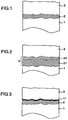
- the interface oxide layer 11 is formed at the interface of the bond coat 2 and the top coat 3, as shown in Fig. 3 .
- Oxygen passing through the top coat 3 is limited as compared with the case where the top coat 3 is absent, so that the oxygen partial pressure on the surface of the bond coat 2 is relatively low.
- no element that is oxidized more easily than aluminum is contained in the bond coat 2. Therefore, aluminum that is the most oxidizable among the components of the bond coat 2 is oxidized preferentially.
- a substantially pure aluminum oxide is formed as the interface oxide layer 11, as shown in Fig. 5A-C .
- the interface oxide layer thus formed does not contain the oxide of an element that is easier to be oxidized than aluminum, so that grain boundary or microcrack caused by such an oxide occurs less often, and the oxygen permeability is very low. As a result, an effect of significantly suppressing the growth of the interface oxide is achieved, and very high durability is exhibited. Therefore, in the case where the high temperature component is used for the bucket or nozzle etc. of a gas turbine having a very high combustion gas temperature, due to the excellent high-temperature durability thereof, the top coat tends to be subjected to no damage such as spalling, so that a thermal barrier effect can be achieved sufficiently over a long-term operation, which is the inherent purpose of the thermal-insulating ceramic layer.
- the decrease in temperature of the metal of the substrate constituting the component improves the reliability of component, and prolongs the service life thereof. Furthermore, since the thermal barrier effect is obtained stably, the amount of blade cooling air for the gas turbine blade can be decreased, and the turbine efficiency can be enhanced.
- the alloy used for the bond coat consists substantially of at least one element of nickel and cobalt, chromium and aluminum.
- it can contain at least one element selected from a group consisting of tantalum, tungsten, silicon, platinum, manganese and boron can be contained in a range of 0 to 20 wt% (including zero percent).
- At least one element of nickel and cobalt is contained, in a total amount of which is in a range of 50 to 75 wt%, that 5 to 40 wt% of chromium is contained, and that 1 to 30.wt% of aluminum is contained.
- Nickel and/or cobalt are/is essential element(s) for the alloy forming the bond coat. At least one element of nickel and cobalt is contained, a total amount of which is 50 to 75 wt%, in order to provide the equivalent thermal expansion coefficient etc. to the heat resistant alloy of substrate by means of providing the similar alloy composition. If the amount thereof is lower than 50 wt%, a bond coat having high ductility is difficult to be formed. If the amount thereof is higher than 75 wt%, the corrosion resistance and the oxidation resistance decrease because amounts of chromium and aluminum become low. Chromium and aluminum are elements for forming a protective oxide film that provides the corrosion resistance and the oxidation resistance.
- Chromium mainly contributes to the corrosion resistance
- aluminum mainly contributes to the oxidation resistance. If the amount of chromium is lower than 5 wt% or the amount of aluminum is lower than 1 wt%, an effect of improving the corrosion resistance and the oxidation resistance becomes little. If the amount of chromium exceeds 40 wt% or the amount of aluminum exceeds 30 wt%, the film is easily subjected to be embrittled.
- One element selected from a group consisting of tantalum, tungsten, silicon, platinum, manganese and boron has an effect of fixing impurities in the bond coat and of enhancing the adhesion between the substrate and the bond coat and the adhesion of the protective oxide film.
- An element that is easier to be oxidized than aluminum such as yttrium, hafnium (Hf), cerium (Ce), lanthanum (La), thorium (Th), samarium (Sm), and neodymium (Nd), is not contained in the alloy forming the bond coat. Thereby, a decrease in oxygen insulating properties due to mixing of such an element in aluminum oxides is suppressed.
- the bond coat is formed by a low-pressure plasma spray technique.
- a high velocity flame spray technique such as a high velocity oxy-fuel spray technique and a high velocity air-fuel spray technique can also be used.
- spraying there is a possibility of mixing a minute amount of a material of a vessel, crucible, atomization nozzle, and the like, during steps such as agglomeration, fusing, crushing, and atomization in the manufacturing process of alloy powder.
- steps such as agglomeration, fusing, crushing, and atomization in the manufacturing process of alloy powder.
- a minute amount of material of an electrode, spray nozzle, and the like during spraying.
- these are unavoidable impurities, and are allowed to be included as unavoidable impurities.
- the high temperature component according to the present invention comprise essentially a substrate 1, the bond coat 2, and the top coat 3 as shown in Fig. 1 .
- the bond coat 2 may have a two-layer structure.
- the bond coat 2 is formed of a second layer 22 which consists substantially of at least one element of nickel and cobalt, chromium, aluminum and at least one element selected from a group consisting of tantalum, tungsten, silicon, platinum, manganese and boron in the range of 0 to 20 wt% (including zero percent), and a first layer 21 which is made of an MCrAlX alloy, wherein M represents at least one element selected from a group consisting of cobalt, nickel and iron, and X represents at least one element selected from a group consisting of yttrium, hafnium, tantalum, cesium, cerium, lanthanum, thorium, tungsten, silicon, platinum, manganese and boron.
- M represents at least one element selected from a group consist
- ZrO 2 -based ceramics are preferable for the top coat 3.
- partially stabilized zirconia containing at least one selected from Y 2 O 3 , MgO, CaO, CeO 2 , Sc 2 O 3 , Er 2 O 3 , Gd 2 O 3 , Yb 2 O 3 , Al 2 O 3 , SiO 2 , and La 2 O 3 is preferable.
- Yttria partially stabilized zirconia is more preferable.
- forming a porous top coat by using an atmospheric plasma spray technique to suppress crack propagation therein; producing a vertical crack in the top coat to relieve thermal stress; forming top coat having a columnar structure by using an electron-beam physical vapour deposition technique to relieve thermal stress by the separation between the columnar structures; and the like.
- these processes can be used as well for the top coat.
- a nickel-based super-alloy (IN738LC: Ni-16 wt% Cr-8.5 wt% Co-1.7 wt% Mo-2.6 wt% W-1.7wt% Ta-0.9 wt% Nb-3.4 wt% Al-3.4 wt% Ti) having a disc shape with a diameter of 25 mm and a thickness of 5 mm was used.
- a bond coat was formed on the substrate by a low-pressure plasma spray technique using CoNiCrAl alloy (Co-32 wt% Ni-21 wt% Cr-8 wt% A1) powder, and heat-treated at a temperature of 1121°C for 4 hours under vacuum, as diffusion heat treatment.
- the thickness of the bond coat was about 100 ⁇ m. Subsequently, a top coat with a thickness of about 200 ⁇ m was formed onto the bond coat on the substrate by the atmospheric plasma spray technique using yttria partially stabilized zirconia (ZrO 2 -8 wt% Y 2 O 3 ) powder.
- Example 2 The same specimen for the substrate as that of Example 1 was used, and a bond coat was formed on the surface thereof by the low-pressure plasma spray technique using NiCoCrAl alloy (Ni-23 wt% Co-17 wt% Cr-12.5 wt% A1) powder. It was heat-treated at 1121°C for 4 hours under vacuum, as diffusion heat treatment. The thickness of bond coat was about 100 ⁇ m. Subsequently, top coats of yttria partially stabilized zirconia (ZrO 2- 8 wt% Y 2 O 3 ) were formed onto the bond coat on the substrate by the following four methods so as to have a thickness of about 200 ⁇ m.
- yttria partially stabilized zirconia ZrO 2- 8 wt% Y 2 O 3
- a first method a top coat having a porosity of about 10% was formed by the atmospheric plasma spray technique.
- a second method a porous top coat having a porosity of about 20% was formed by the atmospheric plasma spray technique.
- a third method a top coat having a vertical crack was formed by the atmospheric plasma spray technique.
- a fourth method a top coat having a columnar structure was formed by the electron-beam physical vapour deposition technique.
- the TBC according to the present invention has better thermal cycle tolerance than that of comparative examples, and thus, has an effect of improving the durability due to a growth suppressing effect of interface oxide. It was also found that comparing the method for forming the top coat, the fourth method has the best thermal cycle tolerance, and in the next place the properties are better in the order of the third method and the second method.
- Example 2 The same specimen for the substrate as that of Example 1 was used, and a bond coat was formed by the low-pressure plasma spray technique.
- the bond coat was formed so as to have a two-layer structure.
- a CoNiCrAlY alloy (Co-32 wt% Ni-21 wt% Cr-8 wt% A1-0.5 wt% Y) was formed so as to have a thickness of about 100 ⁇ m
- a CoNiCrAl alloy (Co-32 wt% Ni-21 wt% Cr-8 wt% A1) was formed so as to have a thickness of about 50 ⁇ m.
- a top coat with a thickness of about 200 ⁇ m and a diameter of 15 mm was formed at the center of the specimen by the atmospheric plasma spray technique using yttria partially stabilized zirconia (ZrO 2 -8 wt% Y 2 O 3 ) powder with using a metallic mask.
- a specimen was also prepared in which the bond coat was formed as a single layer with a thickness of about 150 ⁇ m made of a CoNiCrAl alloy (Co-32 wt% Ni-21 wt% Cr-8 wt% Al), on a part of which the top coat was formed.
- a specimen was also prepared in which the bond coat was formed as a single layer of a CoNiCralY alloy (Co-32 wt% Ni-21 wt% Cr-8 wt% A1-0.5 wt% Y) with a thickness of about 150 ⁇ m.
- a thermal cycle test was conducted on these specimens, in which heating of the specimens at a temperature of 1000°C for 10 hours in the air and cooling of them to 200°C was repeated one hundred times. The test results are given in Table 3.
- Table 3 Specimen Thickness ( ⁇ m) of interface oxide layer Maximum oxidation depth ( ⁇ m) on portion where top coat is absent No.
- the thickness of the interface oxide layer formed between the top coat and the bond coat was 10 ⁇ m or less for both of No. 11 and No. 12 specimens, while the thickness was about 21 ⁇ m for No. 13 specimen.
- the thickness of the oxide layer was nonuniform, and hence it was difficult to exactly determine the oxide film thickness. Therefore, evaluation was made by the maximum value of oxidation depth measured from an initial interface which is determined to be a portion where the top coat starts. The maximum oxidation depth became shallower in the order of No. 11, No. 13 and No. 12 specimens. As for the growth of oxide in the portion where the top coat was absent, the oxidation depth of No. 11 specimen was smallest. The reason thereof is considered to be as follows. In addition to the formation of a highly protective oxide layer on the surface of the second layer for No.
- the bond coat is formed so as to have a two-layer structure having a layer made of an MCrAl alloy and a layer made of an MCrAlX alloy, and that the MCrAl alloy layer is an upper layer.
- FIG. 6 is a perspective view showing the whole configuration of the gas turbine bucket.
- this gas turbine bucket is used as a first-stage bucket of a rotating portion of a gas turbine provided with three-stage buckets for example.
- the bucket was made of a nickel-based heat resistant alloy (Rene'-80:Ni-14% Cr-4% Mo-4% W- 3% A1-5ro Ti-9.5% Co). It has an airfoil portion 61, a platform portion 62, a shank 63, a seal fin 64, and a tip pocket 65, and is attached to a disc via a dovetail 66.
- This bucket has a blade portion having a length of 100 mm, and a length below the platform portion 62 is 120 mm.
- an internal cooling passage (not shown) is provided from the dovetail 66 through the airfoil portion 61 so that a cooling medium, especially air or steam, passes through to cool the bucket from the interior thereof.
- This TBC bucket is most excellent when being used for the first stage, but it can be also provided as the buckets of the second or later stages.
- the TBC according to the present invention was formed in the airfoil portion 61 and the platform portion 62, which are exposed to combustion gas. The film was formed by almost the same method as that in Example 2.
- a bond coat with a thickness of about 200 ⁇ m was formed on the surface of bucket by the low-pressure plasma spray technique using NiCoCrAl alloy (Ni-23 wt% Co-17 wt% Cr-12.5 wt% A1) powder, and a top coat with a thickness of about 300 ⁇ m made of yttria partially stabilized zirconia (ZrO 2 -8 wt% Y 2 O 3 ) having a vertical crack structure was formed on the bond coat by the atmospheric plasma spray technique.
- NiCoCrAl alloy Ni-23 wt% Co-17 wt% Cr-12.5 wt% A1
- a top coat with a thickness of about 300 ⁇ m made of yttria partially stabilized zirconia (ZrO 2 -8 wt% Y 2 O 3 ) having a vertical crack structure was formed on the bond coat by the atmospheric plasma spray technique.
- the turbine bucket manufactured as described above was subjected to oxidation treatment of 1000°C for 1000 hours in the air in order to simulate the oxidized state after long-term use. Then it was subjected to a thermal load test by using a heating test apparatus for simulating an actual machine, shown in Fig. 8 .
- a heating test apparatus for simulating an actual machine shown in Fig. 8 .
- a high-temperature and high-pressure combustion gas 86 is guided into a combustion liner 82, and is exhausted from an exhaust air duct 85 after heating test blades 83 provided on a blade holding stand 84.
- the interior of the test blade 83 is cooled by a cooling air, so that a test simulating the thermal load of the actual machine can be carried out.
- the test conditions were as follows: the combustion gas temperature was 1500°C at a maximum; the cooling air temperature was 170°C; and the pressure was 8 atmospheres.
- the blade substrate temperature in heating was measured by a thermocouple embedded beforehand in the leading edge portion of the bucket. As the result, the heat flux was 3.0 MW/m 2 at a maximum.
- a turbine bucket in which the bond coat was formed of a NiCoCrAlY alloy Ni-23 wt% Co-17 wt% Cr-12.5 wt% Al-0.5 wt% Y
- the turbine bucket provided with the TBC according to the present invention has higher durability than the conventional turbine bucket.
- FIG. 7 is a perspective view showing the whole configuration of the gas turbine nozzle.
- this gas turbine nozzle is used as a first-stage nozzle of a gas turbine provided with three-stage nozzle for example.
- the nozzle was made of a cobalt-based heat resistant alloy (FSX414: Co-10 wt% Ni-29 wt% Cr-7.5 wt% W-1% Fe-0.4% Mn-0.8% Si), and has an airfoil portion 71 and an end wall portion 72.
- FSX414 cobalt-based heat resistant alloy
- an internal cooling passage (not shown) is provided from the end surface of the end wall portion 72 through the airfoil portion 71 so that a cooling medium, especially air or steam, passes through in order to cool the nozzle from 5 the interior thereof.
- This TBC nozzle is most excellent when being used for the first stage, but it can also be provided as the second or later stage.
- the TBC was formed on the inside surfaces of the airfoil portion 71 and the end wall portion 72, which are exposed to combustion gas, by the method of Example 1.
- a bond coat with a thickness of about 200 ⁇ m was formed on the surface of the nozzle by the low-pressure plasma spray technique using CoNiCrAl alloy (Co-32% Ni-21% Cr-8% Al) powder, and a top coat with a thickness of about 300 ⁇ m made of yttria partially stabilized zirconia (ZrO 2 -8 wt% Y 2 O 3 ) having a vertical crack structure was provided on the bond coat by the atmospheric plasma spray technique.
- the turbine nozzle manufactured as described above was subjected to oxidation treatment of 1000°C for 1000 hours in the air in order to simulate the oxidized state after long-term use. Then it was subjected to a thermal load test by a heating test apparatus for simulating the actual machine in the same way as in Example 4. For comparison, a turbine nozzle in which the bond coat was made of a CoNiCrAlY alloy (Co-32% Ni-21% Cr-8% Al-0.5% Y) was also manufactured, and this turbine nozzle was subjected to the similar test.
- the high temperature component with a thermal barrier ceramic coating according to the present invention has a very high durability at high temperatures. Therefore, the high temperature component is suitable as a thermal barrier coating for the bucket, nozzle, combustor, and the like of a gas turbine. Also, it is suitable as a thermal barrier coating of not only a gas turbine but also an aircraft gas turbine engine.
Landscapes
- Chemical & Material Sciences (AREA)
- Engineering & Computer Science (AREA)
- Inorganic Chemistry (AREA)
- Mechanical Engineering (AREA)
- Materials Engineering (AREA)
- Metallurgy (AREA)
- Chemical Kinetics & Catalysis (AREA)
- Organic Chemistry (AREA)
- Ceramic Engineering (AREA)
- General Engineering & Computer Science (AREA)
- Coating By Spraying Or Casting (AREA)
- Other Surface Treatments For Metallic Materials (AREA)
- Turbine Rotor Nozzle Sealing (AREA)
Description
- The present invention relates to a high temperature component with a thermal barrier coating which is made of ceramic. It also relates to a gas turbine in which at least a part of a component is composed of the high temperature component with the thermal barrier coating.
- An operating temperature of a gas turbine has been increasing year by year in order to increase the efficiency thereof. To cope with such a high operating temperature, a thermal barrier coating (which is referred to TBC hereinafter) made of ceramic has been conventionally applied to gas turbine components. As the thermal barrier coating, an MCrAlY alloy layer having high oxidation resistance and a zirconia (ZrO2) based ceramic layer having low thermal conduction are generally formed on a substrate made of a nickel (Ni) based or a cobalt (Co) based alloy (see Example 1 in
JP-A-62-211387 - It is generally known that the substrate temperature can be decreased by 50 to 100°C by the application of the TBC, although it depends on operating conditions. The TBC is very effective in compensating the heat resisting temperature of the substrate. For the TBC used under harsh thermal conditions, however, spalling or damage of the top coat (thermal-insulating ceramic layer) is liable to occur due to a difference in thermal expansion between the TBC and the substrate or a bond coat, a thermal stress caused by a sudden temperature change at the time of starting and stopping of the gas turbine, growth of an oxide layer on the interface between the bond coat and the top coat by oxidation of a metal component in the bond coat, and the like. Especially in a gas turbine with a high operating temperature, spalling of the top coat is liable to occur.
- An object of the present invention is to enhance the durability of a top coat in a high temperature component with a thermal barrier coating.
- According to an aspect of the present invention, a high temperature component with a thermal barrier coating is provides, the thermal barrier coating being formed of an oxide-based ceramic on a bond coat, the bond coat being formed on the surface of a heat resistant alloy substrate composed mainly of at least one element of nickel and cobalt, wherein the bond coat is formed of an alloy comprising substantially at least one element of nickel and cobalt, chromium and aluminum, and wherein the bond coat does not contain an element that is easier to be oxidized than aluminum.
- According to a further aspect of the present invention, a gas turbine is provided in which the whole or a part of a gas turbine component, such as a combustor, a gas turbine bucket, or a gas turbine nozzle, is formed of the high temperature component according to the present invention.
- The high temperature component according to the present invention has higher resistance to spalling in an environment of the gas turbine than the conventional high temperature component in which the top coat is formed on the bond coat made of an MCrAlY alloy. Thus, it can be adapted for high temperatures for operating the gas turbines.
- Other objects, features and advantages of the invention will become apparent from the following description of the embodiments of the invention taken in conjunction with the accompanying drawings.
-
-
Fig. 1 is a schematic cross-sectional view of a high temperature component according to an embodiment of the present invention; -
Fig. 2 is a schematic cross-sectional view of a high temperature component according to another embodiment of the present invention; -
Fig. 3 is a schematic cross-sectional view of a high temperature component after oxidation of the component to which a TBC is applied; -
Figs. 4A-C are schematic cross-sectional views showing a process for forming interface oxides of TBC having an MCrAlY alloy bond coat;Fig. 4A shows a oxygen passing through a top coat;Fig.4B shows local formation of fine particle yttrium oxides; andFig. 4C shows formation of a continuous interface oxide layer including the fine particle yttrium oxides therein. -
Figs. 5A-C are schematic cross-sectional views showing a process for forming interface oxides of TBC having an MCrAl alloy bond coat;Fig. 5A shows a oxygen passing through a top coat;Fig. 5B and 5C shows formation of a continuous interface oxide layer consisting substantially of aluminum oxide. -
Fig. 6 is a perspective view of a turbine bucket provided with a TBC according to the present invention; -
Fig. 7 is a perspective view of a turbine nozzle provided with a TBC according to the present invention; and -
Fig. 8 is a schematic view of a heating test apparatus for simulating an actual machine. - Present inventors investigated causes for spalling of a top coat (thermal-insulating ceramic layer) of a TBC. The top coat is generally made of partially stabilized zirconia because of its low thermal conduction, high thermal-insulating properties, and high toughness. The partially stabilized zirconia allows oxygen to pass therethrough because it has oxygen ion conductivity. In addition, if the top coat is made porous, a vertical crack or a columnar structure is formed to relieve the thermal stress thereof. Resultant pores or cracks serve to pass further oxygen, so that the permeability of oxygen is further increased. Therefore, as oxygen is supplied to the surface of a bond coat all the time from the outside through the top coat, metal components in the bond coat is oxidized, so that an oxide layer is formed and grows at the interface between the top coat and the bond coat. At the early stage of formation of the interface oxide layer, at which the film thickness is small, a protective oxide layer composed mainly of aluminum oxides is formed, so that such formation of interface oxide layer brings about a rather favorable result in light of ensuring of adhesion between the top coat and the bond coat, preventing the metal components from being further oxidized. In actual environments, however, oxygen passes through the interface oxide layer and intrudes into the bond coat, so that the interface oxides grow.
- Thereupon, the inventors investigated the growth of interface oxide layer in detail, and obtained the knowledge as described below. In the conventional TBC, the thermal barrier coating is applied via the bond coat composed of an MCrAlY alloy containing yttrium which is easier to be oxidized than aluminum because yttrium has lower oxygen equilibrium partial pressure than that of aluminum. This is because the MCrAlY alloy has been developed to be used not as the bond coat for the TBC but singly as an oxidation and corrosion resistant coating. In the case where the MCrAlY alloy is used singly as the oxidation and corrosion resistant coating, the coating surface is exposed directly to a high temperature combustion gas, and oxidized under a high oxygen partial pressure. In this case, almost all of alloy elements are generally oxidized at the same time, so that the oxide layer formed on the surface is possibly a composite oxide containing all of alloy components. Thus, it is impossible that the most protective aluminum oxide layer grows singly on the surface preferentially. In this case, generally, the oxygen partial pressure decreases gradually on the surface of the alloy layer under the oxide layer, as the oxide layer grows. Finally, although the highly protective aluminum oxide layer is formed on the surface of alloy layer, the thickness of oxide layer increases, so that spalling of oxides is liable to occur. As countermeasures against the above-described phenomenon, yttrium is added which is easier to be oxidized than aluminum. Thereby, the nucleation of oxides in the region of low oxygen partial pressure just under the surface of the alloy layer is accelerated, and the highly protective aluminum oxide layer is caused to grow preferentially at the early stage, by which high oxidation and corrosion resistance is realized. Furthermore, since yttrium is oxidized under a lower oxygen partial pressure than aluminum, their oxides are formed locally at a considerably deep position in the alloy layer. When aluminum oxides grow with the locally formed oxides being cores, the formed composite oxide layer takes a shape that cuts into the alloy layer locally and deeply so that a so-called "anchor" is dropped. As a result, the adhesion of a protective oxide to the alloy layer can be enhanced.
- In the case where the MCrAlY alloy is used as the bond coat of TBC, however, since yttrium is contained which is easier to be oxidized than aluminum, the top coat is rather liable to be spalled. This reason is explained with reference to
Figs. 4A-C . Whenoxygen 4 passes through atop coat 3 and arrives at a bond coat 2 (seeFig. 4A ), oxygen bonds yttrium at first to form an oxide. Since the added amount of yttrium is small, a continuous oxide film is not formed, but afine particle oxide 12 is formed locally (seeFig. 4B ). Next, an aluminum oxide grows with thefine particle oxide 12 being a core, and hence a continuousinterface oxide layer 11 is formed (Fig. 4C ). Thisinterface oxide layer 11 is a composite oxide layer in which theparticle oxide 12, which is an oxide of yttrium, is dispersedly included. For such a composite oxide layer, a grain boundary is easily formed at the boundary between dispersed particles and a matrix, and a microcrack is liable to occur due to a difference in thermal expansion between the dispersed particles and the matrix, so that oxygen easily passes through as compared with a pure aluminum oxide. As a method for suppressing the growth of interface oxides, a method in which the surface of the bond coat is cleaned by an ionized gas flow to remove unnecessary oxides or pollutants, and then an alumina layer is formed by oxidation, a method in which the surface of the bond coat is melted by laser irradiation in an oxygen atmosphere, by which a barrier layer of alumina is formed, and the like methods are known. However, even if such treatment is performed, alumina formed by oxidation contains yttrium, so that the passing of oxygen cannot be suppressed. - For a gas turbine to which the TBC is applied, the operating temperature thereof is often high, and hence the growth of interface oxides is further accelerated due to the high temperature. When the interface oxide layer grows and the film thickness is increased, a new thermal stress occurs in the top coat due to the accumulation of distortion caused by volume expansion at the time when the metal components are oxidized, a change in thermal and mechanical properties from metal to oxide, and the like, so that the top coat is liable to be damaged. In addition, due to the increased film thickness, the interface oxide layer itself is liable to be subjected to delamination or spalling at the interface. Furthermore, as the interface oxide layer grows, aluminum in the bond coat is lost by oxidation, so that the oxidation of chromium takes place, and finally nickel and cobalt are oxidized. As chromium, nickel and cobalt have greater volume expansion during oxidation than aluminum, further relatively porous oxides are formed. In this state, the interface oxide layer is easily subjected to delamination, which resultantly leads to the spalling of top coat.
- Based on the above-described results of the investigation, the top coat is formed on a heat resistant alloy substrate composed mainly of nickel or cobalt via a bond coat comprising substantially an alloy of chromium, aluminum and at least one element of nickel and cobalt in the present invention.
- When the high temperature component of the present invention is used at a high temperature, the
interface oxide layer 11 is formed at the interface of thebond coat 2 and thetop coat 3, as shown inFig. 3 . Oxygen passing through thetop coat 3 is limited as compared with the case where thetop coat 3 is absent, so that the oxygen partial pressure on the surface of thebond coat 2 is relatively low. In addition, no element that is oxidized more easily than aluminum is contained in thebond coat 2. Therefore, aluminum that is the most oxidizable among the components of thebond coat 2 is oxidized preferentially. As a result, unlike the case where the MCrAlY alloy is used for the bond coat, a substantially pure aluminum oxide is formed as theinterface oxide layer 11, as shown inFig. 5A-C . The interface oxide layer thus formed does not contain the oxide of an element that is easier to be oxidized than aluminum, so that grain boundary or microcrack caused by such an oxide occurs less often, and the oxygen permeability is very low. As a result, an effect of significantly suppressing the growth of the interface oxide is achieved, and very high durability is exhibited. Therefore, in the case where the high temperature component is used for the bucket or nozzle etc. of a gas turbine having a very high combustion gas temperature, due to the excellent high-temperature durability thereof, the top coat tends to be subjected to no damage such as spalling, so that a thermal barrier effect can be achieved sufficiently over a long-term operation, which is the inherent purpose of the thermal-insulating ceramic layer. In addition, the decrease in temperature of the metal of the substrate constituting the component improves the reliability of component, and prolongs the service life thereof. Furthermore, since the thermal barrier effect is obtained stably, the amount of blade cooling air for the gas turbine blade can be decreased, and the turbine efficiency can be enhanced. - In the present invention, the alloy used for the bond coat consists substantially of at least one element of nickel and cobalt, chromium and aluminum. However, it can contain at least one element selected from a group consisting of tantalum, tungsten, silicon, platinum, manganese and boron can be contained in a range of 0 to 20 wt% (including zero percent). At least one element of nickel and cobalt is contained, in a total amount of which is in a range of 50 to 75 wt%, that 5 to 40 wt% of chromium is contained, and that 1 to 30.wt% of aluminum is contained.
- Nickel and/or cobalt are/is essential element(s) for the alloy forming the bond coat. At least one element of nickel and cobalt is contained, a total amount of which is 50 to 75 wt%, in order to provide the equivalent thermal expansion coefficient etc. to the heat resistant alloy of substrate by means of providing the similar alloy composition. If the amount thereof is lower than 50 wt%, a bond coat having high ductility is difficult to be formed. If the amount thereof is higher than 75 wt%, the corrosion resistance and the oxidation resistance decrease because amounts of chromium and aluminum become low. Chromium and aluminum are elements for forming a protective oxide film that provides the corrosion resistance and the oxidation resistance. Chromium mainly contributes to the corrosion resistance, and aluminum mainly contributes to the oxidation resistance. If the amount of chromium is lower than 5 wt% or the amount of aluminum is lower than 1 wt%, an effect of improving the corrosion resistance and the oxidation resistance becomes little. If the amount of chromium exceeds 40 wt% or the amount of aluminum exceeds 30 wt%, the film is easily subjected to be embrittled. One element selected from a group consisting of tantalum, tungsten, silicon, platinum, manganese and boron has an effect of fixing impurities in the bond coat and of enhancing the adhesion between the substrate and the bond coat and the adhesion of the protective oxide film. An element that is easier to be oxidized than aluminum, such as yttrium, hafnium (Hf), cerium (Ce), lanthanum (La), thorium (Th), samarium (Sm), and neodymium (Nd), is not contained in the alloy forming the bond coat. Thereby, a decrease in oxygen insulating properties due to mixing of such an element in aluminum oxides is suppressed.
- The bond coat is formed by a low-pressure plasma spray technique. However, a high velocity flame spray technique such as a high velocity oxy-fuel spray technique and a high velocity air-fuel spray technique can also be used. In the case of spraying, there is a possibility of mixing a minute amount of a material of a vessel, crucible, atomization nozzle, and the like, during steps such as agglomeration, fusing, crushing, and atomization in the manufacturing process of alloy powder. There is also a possibility of mixing a minute amount of material of an electrode, spray nozzle, and the like, during spraying. Thus, these are unavoidable impurities, and are allowed to be included as unavoidable impurities.
- The high temperature component according to the present invention comprise essentially a
substrate 1, thebond coat 2, and thetop coat 3 as shown inFig. 1 . As shown inFig. 2 , thebond coat 2 may have a two-layer structure. In this case, thebond coat 2 is formed of asecond layer 22 which consists substantially of at least one element of nickel and cobalt, chromium, aluminum and at least one element selected from a group consisting of tantalum, tungsten, silicon, platinum, manganese and boron in the range of 0 to 20 wt% (including zero percent), and afirst layer 21 which is made of an MCrAlX alloy, wherein M represents at least one element selected from a group consisting of cobalt, nickel and iron, and X represents at least one element selected from a group consisting of yttrium, hafnium, tantalum, cesium, cerium, lanthanum, thorium, tungsten, silicon, platinum, manganese and boron. In the case where the top coat is not formed on the whole surface of bond coat, and a part of bond coat is exposed, the high temperature component having the bond coat of this structure is preferable because the exposed portion has securely the corrosion resistance and the oxidation resistance. - ZrO2-based ceramics are preferable for the
top coat 3. In particular, partially stabilized zirconia containing at least one selected from Y2O3, MgO, CaO, CeO2, Sc2O3, Er2O3, Gd2O3, Yb2O3, Al2O3, SiO2, and La2O3 is preferable. Yttria partially stabilized zirconia is more preferable. - In order to improve the durability of TBC, following techniques are known: forming a porous top coat by using an atmospheric plasma spray technique to suppress crack propagation therein; producing a vertical crack in the top coat to relieve thermal stress; forming top coat having a columnar structure by using an electron-beam physical vapour deposition technique to relieve thermal stress by the separation between the columnar structures; and the like. In the present invention, these processes can be used as well for the top coat.
- As a specimen for a substrate, a nickel-based super-alloy (IN738LC: Ni-16 wt% Cr-8.5 wt% Co-1.7 wt% Mo-2.6 wt% W-1.7wt% Ta-0.9 wt% Nb-3.4 wt% Al-3.4 wt% Ti) having a disc shape with a diameter of 25 mm and a thickness of 5 mm was used. A bond coat was formed on the substrate by a low-pressure plasma spray technique using CoNiCrAl alloy (Co-32 wt% Ni-21 wt% Cr-8 wt% A1) powder, and heat-treated at a temperature of 1121°C for 4 hours under vacuum, as diffusion heat treatment. The thickness of the bond coat was about 100 µm. Subsequently, a top coat with a thickness of about 200 µm was formed onto the bond coat on the substrate by the atmospheric plasma spray technique using yttria partially stabilized zirconia (ZrO2-8 wt% Y2O3) powder.
- To evaluate the effect for suppressing growth of the interface oxide according to the present invention, an atmospheric oxidation test was conducted at 950°C for 1000 hours on the specimen prepared by the above-described method. The result is given as No.1 in Table 1. For comparison, a specimen in which the material of the bond coat is replaced by a CoNiCrAlY alloy (Co-32 wt% Ni-21 wt% Cr-8 wt% Al-0.5 wt% Y) was also prepared, and the result thereof is given as No. 2 in Table 1.
Table 1 Specimen Thickness (µm) of interface oxide layer after oxidation test at 950°C for 1000 hours No. 1 Present Invention Bond coat: CoNiCrAl alloy 3 No. 2 Comparative example Bond coat: CoNiCrAlY alloy 6 - As is apparent from Table 1, it was found that the interface oxide layer after oxidation test of No. 1 specimen according to the present invention grows to a half of the thickness of that of No. 2 specimen, and thus has an excellent effect of suppressing the growth of interface oxide.
- The same specimen for the substrate as that of Example 1 was used, and a bond coat was formed on the surface thereof by the low-pressure plasma spray technique using NiCoCrAl alloy (Ni-23 wt% Co-17 wt% Cr-12.5 wt% A1) powder. It was heat-treated at 1121°C for 4 hours under vacuum, as diffusion heat treatment. The thickness of bond coat was about 100 µm. Subsequently, top coats of yttria partially stabilized zirconia (ZrO2-8 wt% Y2O3) were formed onto the bond coat on the substrate by the following four methods so as to have a thickness of about 200 µm.
- A first method: a top coat having a porosity of about 10% was formed by the atmospheric plasma spray technique.
- A second method: a porous top coat having a porosity of about 20% was formed by the atmospheric plasma spray technique.
- A third method: a top coat having a vertical crack was formed by the atmospheric plasma spray technique.
- A fourth method: a top coat having a columnar structure was formed by the electron-beam physical vapour deposition technique.
- A thermal cycle test was conducted on these specimens to evaluate the durability of TBC, in which heating of the specimens at a temperature of 1100°C for 10 hours in the air and cooling of them to 200°C were repeated. The number of cycles until the ceramic layer of specimen spalls is given in Table 2. Spalling was judged to occur when the spalling area of ceramic layer becomes 20% or more of the whole area, and the number of cycles until then was determined. As comparative examples, specimens in which the bond coat is made of a NiCoCrAlY alloy (Ni-23 wt% Co-17 wt% Cr-12.5 wt% Al-0.5 wta Y) are given in Table 2.
Table 2 Specimen Number of cycles reaching spalling No. 3 Present Invention Bond coat: NiCoCrAl alloy 25 Topcoat: atmospheric spray (porosity 10%) No. 4 Present Invention Bond coat: NiCoCrAl alloy 62 Top coat: atmospheric spray (porous) No. 5 Present Invention Bond coat: NiCoCrAl alloy 143 Top coat: atmospheric spray (vertical crack) No. 6 Present Invention Bond coat: NiCoCrAl alloy 160 Top coat: electron beam deposition (columnar structure) No. 7 Comparative example Bond coat: NiCoCrAlY alloy 20 Topcoat: atmospheric spray (porosity 10%) No. 8 Comparative example Bond coat: NiCoCrAlY alloy 43 Top coat: atmospheric spray (porous) No 9 Comparative example Bond coat: NiCoCrAlY alloy 84 Top coat: atmospheric spray (vertical crack) No. 10 Comparative example Bond coat: NiCoCrAlY alloy 65 Top coat: electron beam deposition (columnar structure) - As is apparent from Table 2, it was found that in the case where the top coat is formed by the same method, the TBC according to the present invention has better thermal cycle tolerance than that of comparative examples, and thus, has an effect of improving the durability due to a growth suppressing effect of interface oxide. It was also found that comparing the method for forming the top coat, the fourth method has the best thermal cycle tolerance, and in the next place the properties are better in the order of the third method and the second method.
- The same specimen for the substrate as that of Example 1 was used, and a bond coat was formed by the low-pressure plasma spray technique. The bond coat was formed so as to have a two-layer structure. For a first layer on the substrate side, a CoNiCrAlY alloy (Co-32 wt% Ni-21 wt% Cr-8 wt% A1-0.5 wt% Y) was formed so as to have a thickness of about 100 µm, and for a second layer, a CoNiCrAl alloy (Co-32 wt% Ni-21 wt% Cr-8 wt% A1) was formed so as to have a thickness of about 50 µm. Subsequently, it was heat-treated at 1121°C for 4 hours under vacuum, as diffusion heat treatment. Thereafter, a top coat with a thickness of about 200 µm and a diameter of 15 mm was formed at the center of the specimen by the atmospheric plasma spray technique using yttria partially stabilized zirconia (ZrO2-8 wt% Y2O3) powder with using a metallic mask. A specimen was also prepared in which the bond coat was formed as a single layer with a thickness of about 150 µm made of a CoNiCrAl alloy (Co-32 wt% Ni-21 wt% Cr-8 wt% Al), on a part of which the top coat was formed. Furthermore, a specimen was also prepared in which the bond coat was formed as a single layer of a CoNiCralY alloy (Co-32 wt% Ni-21 wt% Cr-8 wt% A1-0.5 wt% Y) with a thickness of about 150 µm. To evaluate the oxidation resistance in the portion where the top coat is absent, a thermal cycle test was conducted on these specimens, in which heating of the specimens at a temperature of 1000°C for 10 hours in the air and cooling of them to 200°C was repeated one hundred times. The test results are given in Table 3.
Table 3 Specimen Thickness (µm) of interface oxide layer Maximum oxidation depth (µm) on portion where top coat is absent No. 11 Present Invention Bond coat: CoNiCrAlY alloy + CoNiCrAl alloy (two layers) 10 18 No. 12 Present Invention Bond coat: CoNiCrAl alloy (single layer) 8 43 No. 13 Comparative example Bond coat; CoNiCrAlY alloy (single layer) 21 36 - No damages such as spalling of the top coat were observed in any of the specimens. As the result of cross-sectional observation, the thickness of the interface oxide layer formed between the top coat and the bond coat was 10 µm or less for both of No. 11 and No. 12 specimens, while the thickness was about 21 µm for No. 13 specimen.
- In the portion where the top coat was not formed, the thickness of the oxide layer was nonuniform, and hence it was difficult to exactly determine the oxide film thickness. Therefore, evaluation was made by the maximum value of oxidation depth measured from an initial interface which is determined to be a portion where the top coat starts. The maximum oxidation depth became shallower in the order of No. 11, No. 13 and No. 12 specimens. As for the growth of oxide in the portion where the top coat was absent, the oxidation depth of No. 11 specimen was smallest. The reason thereof is considered to be as follows. In addition to the formation of a highly protective oxide layer on the surface of the second layer for No. 11 specimen, yttrium contained in the first layer diffuses gradually in the second layer and reaches the surface of the layer during a process in which oxidation proceeds at the time of diffusion heat treatment and at the time when the specimen is held at a high temperature in the test, thereby an anchoring effect of protective oxide layer on the surface is achieved and the adhesion is improved. Thus, the highly protective oxide is kept for long-term thermal exposure. On the other hand, for No. 12 specimen in which the bond coat does not contain yttrium, it is considered that no anchoring effect was achieved although a highly protective oxide is formed, so that local spalling occurred in the surface oxide layer having an increased film thickness at the portion where the top coat is absent during the oxidation process under high oxygen partial pressure. Thus, the maximum oxidation depth for No. 12 was increased. In addition, for No. 13 specimen, it is considered that the mixing of yttrium oxide in the protective oxide layer decreased the protecting properties, although spalling of oxide layer does not occur due to the anchoring effect achieved by the addition of yttrium, so that the maximum oxidation depth was also increased.
- From the above, in the case where the portion in which the top coat is not provided, it is preferable that the bond coat is formed so as to have a two-layer structure having a layer made of an MCrAl alloy and a layer made of an MCrAlX alloy, and that the MCrAl alloy layer is an upper layer.
- A TBC gas turbine bucket was manufactured.
Fig. 6 is a perspective view showing the whole configuration of the gas turbine bucket. InFig. 6 , this gas turbine bucket is used as a first-stage bucket of a rotating portion of a gas turbine provided with three-stage buckets for example. The bucket was made of a nickel-based heat resistant alloy (Rene'-80:Ni-14% Cr-4% Mo-4% W- 3% A1-5ro Ti-9.5% Co). It has anairfoil portion 61, aplatform portion 62, ashank 63, aseal fin 64, and atip pocket 65, and is attached to a disc via adovetail 66. This bucket has a blade portion having a length of 100 mm, and a length below theplatform portion 62 is 120 mm. In the bucket, an internal cooling passage (not shown) is provided from thedovetail 66 through theairfoil portion 61 so that a cooling medium, especially air or steam, passes through to cool the bucket from the interior thereof. This TBC bucket is most excellent when being used for the first stage, but it can be also provided as the buckets of the second or later stages. In this gas turbine blade, the TBC according to the present invention was formed in theairfoil portion 61 and theplatform portion 62, which are exposed to combustion gas. The film was formed by almost the same method as that in Example 2. A bond coat with a thickness of about 200 µm was formed on the surface of bucket by the low-pressure plasma spray technique using NiCoCrAl alloy (Ni-23 wt% Co-17 wt% Cr-12.5 wt% A1) powder, and a top coat with a thickness of about 300 µm made of yttria partially stabilized zirconia (ZrO2-8 wt% Y2O3) having a vertical crack structure was formed on the bond coat by the atmospheric plasma spray technique. - The turbine bucket manufactured as described above was subjected to oxidation treatment of 1000°C for 1000 hours in the air in order to simulate the oxidized state after long-term use. Then it was subjected to a thermal load test by using a heating test apparatus for simulating an actual machine, shown in
Fig. 8 . In this test apparatus a high-temperature and high-pressure combustion gas 86 is guided into acombustion liner 82, and is exhausted from anexhaust air duct 85 afterheating test blades 83 provided on ablade holding stand 84. The interior of thetest blade 83 is cooled by a cooling air, so that a test simulating the thermal load of the actual machine can be carried out. The test conditions were as follows: the combustion gas temperature was 1500°C at a maximum; the cooling air temperature was 170°C; and the pressure was 8 atmospheres. The blade substrate temperature in heating was measured by a thermocouple embedded beforehand in the leading edge portion of the bucket. As the result, the heat flux was 3.0 MW/m2 at a maximum. For comparison, a turbine bucket in which the bond coat was formed of a NiCoCrAlY alloy (Ni-23 wt% Co-17 wt% Cr-12.5 wt% Al-0.5 wt% Y) was also manufactured. - In the case where the combustion gas temperature was 1000°C (heat flux: 0.9 MW/m2), a cycle of start, steady holding and stop, which was repeated 10 times, does not damage to the TBC on both of the turbine bucket according to the present invention and that of comparative example. However, in the case where the combustion gas temperature was 1300°C (heat flux: 1.5 MW/m2), after the cycle was repeated 10 times, spalling of the top coat was observed in a part of leading edge and suction side of the turbine blade of comparative example. The turbine blade according to the present invention was sound. Furthermore, in the case where the combustion gas temperature was 1500°C (heat flux: 3.0 MW/m2), even after the cycle was repeated 10 times, the turbine blade according to the present invention was entirely sound. For the turbine blade of comparative example, the damage range at the leading edge and on the suction side was expanded as compared with the case where the heating temperature was 1300°C, and spalling damage was also observed in a part of pressure side.
- From the above result, it was found that the turbine bucket provided with the TBC according to the present invention has higher durability than the conventional turbine bucket.
- A TEC gas turbine nozzle was manufactured.
Fig. 7 is a perspective view showing the whole configuration of the gas turbine nozzle. InFig. 7 , this gas turbine nozzle is used as a first-stage nozzle of a gas turbine provided with three-stage nozzle for example. The nozzle was made of a cobalt-based heat resistant alloy (FSX414: Co-10 wt% Ni-29 wt% Cr-7.5 wt% W-1% Fe-0.4% Mn-0.8% Si), and has anairfoil portion 71 and anend wall portion 72. In the nozzle, an internal cooling passage (not shown) is provided from the end surface of theend wall portion 72 through theairfoil portion 71 so that a cooling medium, especially air or steam, passes through in order to cool the nozzle from 5 the interior thereof. This TBC nozzle is most excellent when being used for the first stage, but it can also be provided as the second or later stage. In this gas turbine nozzle, the TBC was formed on the inside surfaces of theairfoil portion 71 and theend wall portion 72, which are exposed to combustion gas, by the method of Example 1. Specifically, a bond coat with a thickness of about 200 µm was formed on the surface of the nozzle by the low-pressure plasma spray technique using CoNiCrAl alloy (Co-32% Ni-21% Cr-8% Al) powder, and a top coat with a thickness of about 300 µm made of yttria partially stabilized zirconia (ZrO2-8 wt% Y2O3) having a vertical crack structure was provided on the bond coat by the atmospheric plasma spray technique. - The turbine nozzle manufactured as described above was subjected to oxidation treatment of 1000°C for 1000 hours in the air in order to simulate the oxidized state after long-term use. Then it was subjected to a thermal load test by a heating test apparatus for simulating the actual machine in the same way as in Example 4. For comparison, a turbine nozzle in which the bond coat was made of a CoNiCrAlY alloy (Co-32% Ni-21% Cr-8% Al-0.5% Y) was also manufactured, and this turbine nozzle was subjected to the similar test.
- As the result of test, in the case where the combustion gas temperature was 1500°C (heat flux: 3.0 Mw/m2), even after the cycle was repeated 10 times, the turbine nozzle according to the present invention was entirely sound, but in the turbine nozzle of comparative example, spalling damage of the top coat occurred in a part of leading edge, suction side, and pressure side thereof. From this result, it was found that the turbine nozzle according to the present invention has higher durability than the conventional turbine nozzle.
- The high temperature component with a thermal barrier ceramic coating according to the present invention has a very high durability at high temperatures. Therefore, the high temperature component is suitable as a thermal barrier coating for the bucket, nozzle, combustor, and the like of a gas turbine. Also, it is suitable as a thermal barrier coating of not only a gas turbine but also an aircraft gas turbine engine.
- The features and compositions of the above described embodiments may be exchanged or combined to form further embodiments optimized for the respective application. As far as such modifications are readily apparent for an expert skilled in the art they shall be disclosed implicitly by the above description of embodiments without mentioning every possible combination explicitly for the sake of legibility and conciseness of the description.
- It should be further understood by those skilled in the art that although the foregoing description has been made on embodiments of the invention, the invention is not limited thereto and various changes and modifications may be made without departing from the spirit of the invention and the scope of the appended claims.
Claims (11)
- A high temperature component with a thermal barrier coating, comprising: a heat resistant alloy substrate composed mainly of at least one element of nickel and cobalt; a bond coat (2) formed by a low-pressure plasma spray on the surface of the substrate; and a top coat (3) formed of a zirconia-based ceramic on a bond coat,
characterized in that the bond coat is formed of an alloy which consists of:at least one element of nickel and cobalt, a total amount of which is in the range of 50 to 75 wt%;5 to 40 wt% of chromium;1 to 30 wt% of aluminum; optionallyat least one element selected from a group consisting of tantalum, tungsten, silicon, platinum, manganese and boron in a range of up to 20 wt%; and unavoidable impurities, and in that the component has an interface oxide layer consisting of aluminum oxide between the bond coat and the top coat. - The high temperature component with a thermal barrier coating according to claim 1, wherein the oxide-based ceramic of the top coat (3) is made of partially stabilized zirconia.
- High temperature component according to claim 2, wherein the partially stabilized zirconia is yttria partially stabilized zirconia.
- High temperature component according to at least one of the preceding claims, wherein the bond coat (2) is formed by plasma spray.
- High temperature component according to at least one of the preceding claims, wherein the bond coat (2) consists of:a first layer made of an MCrAlX alloy, wherein M is at least one element selected from a group consisting of cobalt, nickel and iron, and X is at least one element selected from a group consisting of yttrium, hafnium, tantalum, cerium, lanthanum, thorium, tungsten, silicon, platinum, manganese and boron; anda second layer made of an alloy as defined in claim 1,wherein the second layer is formed on the first layer, and the top coat (3) is formed on the second layer.
- High temperature component according to claim 5, wherein X in the first layer is yttrium.
- High temperature component according to claim 5 or 6, wherein the first layer is made of a CoNiCrAlY alloy or a NiCoCrAlY alloy.
- High temperature component according to claim 5, 6 or 7, wherein the top coat is formed in a region on a part of the second layer, and the remaining part of the second layer is exposed.
- High temperature component according to claim 5, wherein the top coat (3) is formed in a region on a part of the second layer, and the remaining part of the second layer is exposed.
- A gas turbine provided with a high temperature component according to any of the preceding claims.
- The gas turbine according to claim 10, wherein at least a part of at least one of a combustor, a gas turbine bucket, and a gas turbine nozzle is formed of the high temperature component with a thermal barrier coating.
Applications Claiming Priority (1)
| Application Number | Priority Date | Filing Date | Title |
|---|---|---|---|
| JP2004281377A JP4607530B2 (en) | 2004-09-28 | 2004-09-28 | Heat resistant member having a thermal barrier coating and gas turbine |
Publications (4)
| Publication Number | Publication Date |
|---|---|
| EP1640477A2 EP1640477A2 (en) | 2006-03-29 |
| EP1640477A3 EP1640477A3 (en) | 2006-08-16 |
| EP1640477B1 EP1640477B1 (en) | 2010-05-12 |
| EP1640477B2 true EP1640477B2 (en) | 2018-11-07 |
Family
ID=35453496
Family Applications (1)
| Application Number | Title | Priority Date | Filing Date |
|---|---|---|---|
| EP05021040.0A Ceased EP1640477B2 (en) | 2004-09-28 | 2005-09-27 | High temperature component with thermal barrier coating and gas turbine using the same |
Country Status (4)
| Country | Link |
|---|---|
| US (1) | US7901790B2 (en) |
| EP (1) | EP1640477B2 (en) |
| JP (1) | JP4607530B2 (en) |
| DE (1) | DE602005021191D1 (en) |
Families Citing this family (42)
| Publication number | Priority date | Publication date | Assignee | Title |
|---|---|---|---|---|
| CA2582312C (en) * | 2006-05-05 | 2014-05-13 | Sulzer Metco Ag | A method for the manufacture of a coating |
| US7507484B2 (en) * | 2006-12-01 | 2009-03-24 | Siemens Energy, Inc. | Bond coat compositions and arrangements of same capable of self healing |
| JP5082563B2 (en) * | 2007-04-18 | 2012-11-28 | 株式会社日立製作所 | Heat-resistant member with thermal barrier coating |
| US8511993B2 (en) * | 2009-08-14 | 2013-08-20 | Alstom Technology Ltd. | Application of dense vertically cracked and porous thermal barrier coating to a gas turbine component |
| WO2012053517A1 (en) * | 2010-10-19 | 2012-04-26 | 独立行政法人物質・材料研究機構 | Ni-based superalloy member having heat-resistant bond coat layer formed therein |
| US10227678B2 (en) | 2011-06-09 | 2019-03-12 | General Electric Company | Cobalt-nickel base alloy and method of making an article therefrom |
| DE102012200560B4 (en) | 2012-01-16 | 2014-08-21 | Fraunhofer-Gesellschaft zur Förderung der angewandten Forschung e.V. | A method of producing a ceramic layer on a surface formed of a Ni-based alloy and a ceramic layer article |
| CA2809080C (en) | 2012-03-14 | 2017-03-07 | Mitek Holdings, Inc. | Mounting arrangement for panel veneer structures |
| US8800241B2 (en) | 2012-03-21 | 2014-08-12 | Mitek Holdings, Inc. | Backup wall reinforcement with T-type anchor |
| US8904730B2 (en) | 2012-03-21 | 2014-12-09 | Mitek Holdings, Inc. | Thermally-isolated anchoring systems for cavity walls |
| US8898980B2 (en) | 2012-09-15 | 2014-12-02 | Mitek Holdings, Inc. | Pullout resistant pintle and anchoring system utilizing the same |
| US8839581B2 (en) | 2012-09-15 | 2014-09-23 | Mitek Holdings, Inc. | High-strength partially compressed low profile veneer tie and anchoring system utilizing the same |
| US8881488B2 (en) | 2012-12-26 | 2014-11-11 | Mitek Holdings, Inc. | High-strength ribbon loop anchors and anchoring systems utilizing the same |
| US9038351B2 (en) | 2013-03-06 | 2015-05-26 | Columbia Insurance Company | Thermally coated wall anchor and anchoring systems with in-cavity thermal breaks for cavity walls |
| US9273559B2 (en) * | 2013-03-08 | 2016-03-01 | General Electric Company | Turbine blade cooling channel formation |
| US8863460B2 (en) * | 2013-03-08 | 2014-10-21 | Columbia Insurance Company | Thermally coated wall anchor and anchoring systems with in-cavity thermal breaks |
| US8978326B2 (en) | 2013-03-12 | 2015-03-17 | Columbia Insurance Company | High-strength partition top anchor and anchoring system utilizing the same |
| US8833003B1 (en) | 2013-03-12 | 2014-09-16 | Columbia Insurance Company | High-strength rectangular wire veneer tie and anchoring systems utilizing the same |
| US8910445B2 (en) | 2013-03-13 | 2014-12-16 | Columbia Insurance Company | Thermally isolated anchoring system |
| US8844229B1 (en) | 2013-03-13 | 2014-09-30 | Columbia Insurance Company | Channel anchor with insulation holder and anchoring system using the same |
| US9260857B2 (en) | 2013-03-14 | 2016-02-16 | Columbia Insurance Company | Fail-safe anchoring systems for cavity walls |
| US8904726B1 (en) | 2013-06-28 | 2014-12-09 | Columbia Insurance Company | Vertically adjustable disengagement prevention veneer tie and anchoring system utilizing the same |
| US8978330B2 (en) | 2013-07-03 | 2015-03-17 | Columbia Insurance Company | Pullout resistant swing installation tie and anchoring system utilizing the same |
| US9121169B2 (en) * | 2013-07-03 | 2015-09-01 | Columbia Insurance Company | Veneer tie and wall anchoring systems with in-cavity ceramic and ceramic-based thermal breaks |
| US9038350B2 (en) | 2013-10-04 | 2015-05-26 | Columbia Insurance Company | One-piece dovetail veneer tie and wall anchoring system with in-cavity thermal breaks |
| US8904727B1 (en) | 2013-10-15 | 2014-12-09 | Columbia Insurance Company | High-strength vertically compressed veneer tie anchoring systems utilizing and the same |
| EP3080321B1 (en) | 2013-12-10 | 2019-07-31 | United Technologies Corporation | Method for electrodepositing a nickel-chromium alloy |
| US10669851B2 (en) * | 2013-12-10 | 2020-06-02 | Raytheon Technologies Corporation | Nickel-chromium-aluminum composite by electrodeposition |
| EP3080323B1 (en) | 2013-12-11 | 2019-05-15 | United Technologies Corporation | Electroformed nickel-chromium alloy |
| US9140001B1 (en) | 2014-06-24 | 2015-09-22 | Columbia Insurance Company | Thermal wall anchor |
| US9334646B2 (en) | 2014-08-01 | 2016-05-10 | Columbia Insurance Company | Thermally-isolated anchoring systems with split tail veneer tie for cavity walls |
| US9273461B1 (en) | 2015-02-23 | 2016-03-01 | Columbia Insurance Company | Thermal veneer tie and anchoring system |
| JP2017001235A (en) * | 2015-06-08 | 2017-01-05 | トヨタ自動車株式会社 | Thermal insulation structure |
| US10407892B2 (en) | 2015-09-17 | 2019-09-10 | Columbia Insurance Company | High-strength partition top anchor and anchoring system utilizing the same |
| USD846973S1 (en) | 2015-09-17 | 2019-04-30 | Columbia Insurance Company | High-strength partition top anchor |
| US20170159285A1 (en) | 2015-12-04 | 2017-06-08 | Columbia Insurance Company | Thermal wall anchor |
| US10822966B2 (en) | 2016-05-09 | 2020-11-03 | General Electric Company | Thermal barrier system with bond coat barrier |
| US10738644B2 (en) * | 2017-08-30 | 2020-08-11 | General Electric Company | Turbine blade and method of forming blade tip for eliminating turbine blade tip wear in rubbing |
| CN114058999A (en) * | 2021-11-19 | 2022-02-18 | 西安热工研究院有限公司 | Thermal barrier coating for inhibiting mutual diffusion of elements of base body/thermal barrier coating bonding layer |
| CN114411081A (en) * | 2021-11-19 | 2022-04-29 | 中国航发北京航空材料研究院 | A yttrium hafnium doped aluminum cobalt chromium iron nickel silicon high-entropy thermal barrier bonding layer |
| DE102022200711A1 (en) * | 2022-01-24 | 2023-07-27 | Siemens Energy Global GmbH & Co. KG | Partially coated turbine blade, rotor and method |
| CN117325520A (en) * | 2023-09-19 | 2024-01-02 | 西安交通大学 | Double-layer bonding layer alloy for high-temperature alloy and application thereof |
Citations (15)
| Publication number | Priority date | Publication date | Assignee | Title |
|---|---|---|---|---|
| US3874901A (en) † | 1973-04-23 | 1975-04-01 | Gen Electric | Coating system for superalloys |
| US4095003A (en) † | 1976-09-09 | 1978-06-13 | Union Carbide Corporation | Duplex coating for thermal and corrosion protection |
| US4101715A (en) † | 1977-06-09 | 1978-07-18 | General Electric Company | High integrity CoCrAl(Y) coated nickel-base superalloys |
| US4123595A (en) † | 1977-09-22 | 1978-10-31 | General Electric Company | Metallic coated article |
| JPH04147957A (en) † | 1990-10-09 | 1992-05-21 | Toyota Motor Corp | Heat insulating aluminum-based member |
| US5863668A (en) † | 1997-10-29 | 1999-01-26 | The United States Of America As Represented By The Administrator Of The National Aeronautics And Space Administration | Controlled thermal expansion coat for thermal barrier coatings |
| WO1999043861A1 (en) † | 1998-02-28 | 1999-09-02 | General Electric Company | Multilayer bond coat for a thermal barrier coating system and process therefor |
| JPH11268175A (en) † | 1998-03-19 | 1999-10-05 | Kawasaki Heavy Ind Ltd | Ceramic thermal barrier coating |
| US6283715B1 (en) † | 1999-08-11 | 2001-09-04 | General Electric Company | Coated turbine component and its fabrication |
| US6376015B1 (en) † | 1996-11-30 | 2002-04-23 | Rolls-Royce, Plc | Thermal barrier coating for a superalloy article and a method of application thereof |
| US20020132132A1 (en) † | 2000-12-12 | 2002-09-19 | Sudhangshu Bose | Method of forming an active-element containing aluminide as stand alone coating and as bond coat and coated article |
| DE69902316T2 (en) † | 1998-06-04 | 2003-03-27 | Snecma Moteurs, Paris | Ceramic-based coating with low thermal conductivity |
| EP1321541A2 (en) † | 2001-12-20 | 2003-06-25 | General Electric Company | Nickel aluminide coating and coating systems formed therewith |
| EP1365044A1 (en) † | 2002-05-24 | 2003-11-26 | Siemens Aktiengesellschaft | MCrAl-coating |
| EP1380672A1 (en) † | 2002-07-09 | 2004-01-14 | Siemens Aktiengesellschaft | Highly oxidation resistant component |
Family Cites Families (24)
| Publication number | Priority date | Publication date | Assignee | Title |
|---|---|---|---|---|
| USRE29853E (en) * | 1972-09-18 | 1978-11-28 | The Tappan Company | Gas igniter |
| DE8013163U1 (en) * | 1980-05-16 | 1988-10-13 | MTU Motoren- und Turbinen-Union München GmbH, 8000 München | Housing for a thermal turbomachine with a heat-insulating lining |
| US4585481A (en) * | 1981-08-05 | 1986-04-29 | United Technologies Corporation | Overlays coating for superalloys |
| JPS5887273A (en) * | 1981-11-18 | 1983-05-25 | Hitachi Ltd | Parts having ceramic coated layer and their production |
| JPS60194056A (en) * | 1984-03-14 | 1985-10-02 | Hitachi Ltd | Heat-resistant components with ceramic coating layer |
| US4588607A (en) * | 1984-11-28 | 1986-05-13 | United Technologies Corporation | Method of applying continuously graded metallic-ceramic layer on metallic substrates |
| JPS61207566A (en) * | 1985-03-12 | 1986-09-13 | Showa Denko Kk | Ceramic thermal spray coating formation method |
| JPS62211387A (en) | 1986-03-12 | 1987-09-17 | Hitachi Ltd | Production of ceramic coated heat resistant member |
| JPS62274062A (en) * | 1986-05-23 | 1987-11-28 | Toyota Motor Corp | Production of ceramic coated member |
| JPS6396257A (en) * | 1986-10-11 | 1988-04-27 | Sanwa Tokushu Seiko Kk | Metallic material for undercoat before ceramic coating |
| US4900640A (en) * | 1988-04-19 | 1990-02-13 | Inco Limited | Low coefficient of expansion alloys having a thermal barrier |
| US5176964A (en) * | 1991-04-12 | 1993-01-05 | Martin Marietta Corporation | Diffuse black plasma sprayed coatings |
| US6096381A (en) * | 1997-10-27 | 2000-08-01 | General Electric Company | Process for densifying and promoting inter-particle bonding of a bond coat for a thermal barrier coating |
| DE59801544D1 (en) * | 1997-11-03 | 2001-10-25 | Siemens Ag | PRODUCT WITH A LAYER PROTECTION AGAINST A HOT AGGRESSIVE GAS |
| US6001492A (en) * | 1998-03-06 | 1999-12-14 | General Electric Company | Graded bond coat for a thermal barrier coating system |
| JP2002513081A (en) * | 1998-04-29 | 2002-05-08 | シーメンス アクチエンゲゼルシヤフト | Product with corrosion protection layer and method of manufacturing corrosion protection layer |
| US6089825A (en) * | 1998-12-18 | 2000-07-18 | United Technologies Corporation | Abradable seal having improved properties and method of producing seal |
| UA56228C2 (en) * | 1999-11-01 | 2003-05-15 | Міжнародний Центр Електронно-Променевих Технологій Інституту Електрозварювання Ім. Е.О.Патона Нану | Composite ingot for producing by evaporating a functionally gradient cover with outer ceramic layer on metal lining (versions) |
| JP2001329358A (en) * | 2000-05-19 | 2001-11-27 | Mitsubishi Heavy Ind Ltd | Heat-insulated member, its manufacturing method, turbine blade, and gas turbine |
| US6497758B1 (en) * | 2000-07-12 | 2002-12-24 | General Electric Company | Method for applying a high-temperature bond coat on a metal substrate, and related compositions and articles |
| JP4166978B2 (en) * | 2001-12-17 | 2008-10-15 | 三菱重工業株式会社 | High temperature corrosion resistant alloy material, thermal barrier coating material, turbine member, and gas turbine |
| US7157151B2 (en) * | 2002-09-11 | 2007-01-02 | Rolls-Royce Corporation | Corrosion-resistant layered coatings |
| JP2004256855A (en) * | 2003-02-25 | 2004-09-16 | Japan Fine Ceramics Center | Thermal barrier coating member and method of manufacturing the same |
| US7378132B2 (en) * | 2004-12-14 | 2008-05-27 | Honeywell International, Inc. | Method for applying environmental-resistant MCrAlY coatings on gas turbine components |
-
2004
- 2004-09-28 JP JP2004281377A patent/JP4607530B2/en not_active Expired - Fee Related
-
2005
- 2005-09-23 US US11/233,379 patent/US7901790B2/en not_active Expired - Fee Related
- 2005-09-27 EP EP05021040.0A patent/EP1640477B2/en not_active Ceased
- 2005-09-27 DE DE602005021191T patent/DE602005021191D1/en active Active
Patent Citations (16)
| Publication number | Priority date | Publication date | Assignee | Title |
|---|---|---|---|---|
| US3874901A (en) † | 1973-04-23 | 1975-04-01 | Gen Electric | Coating system for superalloys |
| US4095003A (en) † | 1976-09-09 | 1978-06-13 | Union Carbide Corporation | Duplex coating for thermal and corrosion protection |
| US4101715A (en) † | 1977-06-09 | 1978-07-18 | General Electric Company | High integrity CoCrAl(Y) coated nickel-base superalloys |
| US4123595A (en) † | 1977-09-22 | 1978-10-31 | General Electric Company | Metallic coated article |
| JPH04147957A (en) † | 1990-10-09 | 1992-05-21 | Toyota Motor Corp | Heat insulating aluminum-based member |
| US6376015B1 (en) † | 1996-11-30 | 2002-04-23 | Rolls-Royce, Plc | Thermal barrier coating for a superalloy article and a method of application thereof |
| US5863668A (en) † | 1997-10-29 | 1999-01-26 | The United States Of America As Represented By The Administrator Of The National Aeronautics And Space Administration | Controlled thermal expansion coat for thermal barrier coatings |
| WO1999043861A1 (en) † | 1998-02-28 | 1999-09-02 | General Electric Company | Multilayer bond coat for a thermal barrier coating system and process therefor |
| JPH11268175A (en) † | 1998-03-19 | 1999-10-05 | Kawasaki Heavy Ind Ltd | Ceramic thermal barrier coating |
| DE69902316T2 (en) † | 1998-06-04 | 2003-03-27 | Snecma Moteurs, Paris | Ceramic-based coating with low thermal conductivity |
| US6283715B1 (en) † | 1999-08-11 | 2001-09-04 | General Electric Company | Coated turbine component and its fabrication |
| US20020132132A1 (en) † | 2000-12-12 | 2002-09-19 | Sudhangshu Bose | Method of forming an active-element containing aluminide as stand alone coating and as bond coat and coated article |
| EP1321541A2 (en) † | 2001-12-20 | 2003-06-25 | General Electric Company | Nickel aluminide coating and coating systems formed therewith |
| EP1365044A1 (en) † | 2002-05-24 | 2003-11-26 | Siemens Aktiengesellschaft | MCrAl-coating |
| EP1380672A1 (en) † | 2002-07-09 | 2004-01-14 | Siemens Aktiengesellschaft | Highly oxidation resistant component |
| WO2004005581A1 (en) † | 2002-07-09 | 2004-01-15 | Siemens Aktiengesellschaft | Highly oxidation resistant component |
Non-Patent Citations (3)
| Title |
|---|
| Proc. 5 th. european Conf. Adv. Materials and Processess and Applications, romat 07, Vol. 1,S. 223-226 † |
| SHINDE S.L. ET AL: "Degradation mechanisms in thermal-barrier coatings", CERAM. ENG. SCI. PROC., vol. I., no. 7, 1986, pages 1032 - 1038 † |
| YANAR N.M. ET AL: "Microstructural characterization of the failures of thermal barrier coatings on Ni-base superalloys", MATERIALS AT HIGH TEMPERATURES, vol. 20, no. 4, 2003, pages 495 - 506 † |
Also Published As
| Publication number | Publication date |
|---|---|
| JP2006097042A (en) | 2006-04-13 |
| JP4607530B2 (en) | 2011-01-05 |
| EP1640477A3 (en) | 2006-08-16 |
| DE602005021191D1 (en) | 2010-06-24 |
| US20060251916A1 (en) | 2006-11-09 |
| EP1640477B1 (en) | 2010-05-12 |
| EP1640477A2 (en) | 2006-03-29 |
| US7901790B2 (en) | 2011-03-08 |
Similar Documents
| Publication | Publication Date | Title |
|---|---|---|
| EP1640477B2 (en) | High temperature component with thermal barrier coating and gas turbine using the same | |
| JP5082563B2 (en) | Heat-resistant member with thermal barrier coating | |
| US7374825B2 (en) | Protection of thermal barrier coating by an impermeable barrier coating | |
| US6352788B1 (en) | Thermal barrier coating | |
| EP1939317A2 (en) | Thermal barrier coating | |
| EP1840238A2 (en) | Oxidation-resistant coating and formation method thereof, thermal barrier coating, heat-resistant member, and gas turbine | |
| US20070160859A1 (en) | Layered thermal barrier coatings containing lanthanide series oxides for improved resistance to CMAS degradation | |
| US20160333455A1 (en) | Thermal Barrier Coating with Lower Thermal Conductivity | |
| US7537806B2 (en) | Method for producing a thermal barrier coating on a substrate | |
| US12012869B2 (en) | Part coated with a composition for protection against CMAS with controlled cracking, and corresponding treatment method | |
| JP2019507828A (en) | Adhesion promoting layer for bonding a high temperature protective layer on a substrate and method for producing the same | |
| US7306859B2 (en) | Thermal barrier coating system and process therefor | |
| US7229705B1 (en) | Mischmetal oxide TBC | |
| EP1400607A1 (en) | Thermal barrier coating with improved strength and fracture toughness | |
| JP5281995B2 (en) | Heat resistant member having a thermal barrier coating and gas turbine | |
| RU2851649C1 (en) | Gas turbine blade with multilayer heat shielding coating | |
| EP2423347A1 (en) | Method for forming a thermal barrier coating and a turbine component with the thermal barrier coating | |
| WO2014184906A1 (en) | Heat shield coating member |
Legal Events
| Date | Code | Title | Description |
|---|---|---|---|
| PUAI | Public reference made under article 153(3) epc to a published international application that has entered the european phase |
Free format text: ORIGINAL CODE: 0009012 |
|
| AK | Designated contracting states |
Kind code of ref document: A2 Designated state(s): AT BE BG CH CY CZ DE DK EE ES FI FR GB GR HU IE IS IT LI LT LU LV MC NL PL PT RO SE SI SK TR |
|
| AX | Request for extension of the european patent |
Extension state: AL BA HR MK YU |
|
| PUAL | Search report despatched |
Free format text: ORIGINAL CODE: 0009013 |
|
| AK | Designated contracting states |
Kind code of ref document: A3 Designated state(s): AT BE BG CH CY CZ DE DK EE ES FI FR GB GR HU IE IS IT LI LT LU LV MC NL PL PT RO SE SI SK TR |
|
| AX | Request for extension of the european patent |
Extension state: AL BA HR MK YU |
|
| 17P | Request for examination filed |
Effective date: 20070216 |
|
| AKX | Designation fees paid |
Designated state(s): DE FR GB IT |
|
| 17Q | First examination report despatched |
Effective date: 20070416 |
|
| GRAP | Despatch of communication of intention to grant a patent |
Free format text: ORIGINAL CODE: EPIDOSNIGR1 |
|
| GRAS | Grant fee paid |
Free format text: ORIGINAL CODE: EPIDOSNIGR3 |
|
| GRAA | (expected) grant |
Free format text: ORIGINAL CODE: 0009210 |
|
| AK | Designated contracting states |
Kind code of ref document: B1 Designated state(s): DE FR GB IT |
|
| REG | Reference to a national code |
Ref country code: GB Ref legal event code: FG4D |
|
| REF | Corresponds to: |
Ref document number: 602005021191 Country of ref document: DE Date of ref document: 20100624 Kind code of ref document: P |
|
| PLBI | Opposition filed |
Free format text: ORIGINAL CODE: 0009260 |
|
| 26 | Opposition filed |
Opponent name: SIEMENS AKTIENGESELLSCHAFT Effective date: 20100826 |
|
| PLAX | Notice of opposition and request to file observation + time limit sent |
Free format text: ORIGINAL CODE: EPIDOSNOBS2 |
|
| PLBB | Reply of patent proprietor to notice(s) of opposition received |
Free format text: ORIGINAL CODE: EPIDOSNOBS3 |
|
| PLCK | Communication despatched that opposition was rejected |
Free format text: ORIGINAL CODE: EPIDOSNREJ1 |
|
| APBM | Appeal reference recorded |
Free format text: ORIGINAL CODE: EPIDOSNREFNO |
|
| APBP | Date of receipt of notice of appeal recorded |
Free format text: ORIGINAL CODE: EPIDOSNNOA2O |
|
| APAH | Appeal reference modified |
Free format text: ORIGINAL CODE: EPIDOSCREFNO |
|
| APBQ | Date of receipt of statement of grounds of appeal recorded |
Free format text: ORIGINAL CODE: EPIDOSNNOA3O |
|
| REG | Reference to a national code |
Ref country code: DE Ref legal event code: R082 Ref document number: 602005021191 Country of ref document: DE Representative=s name: BEETZ & PARTNER PATENT- UND RECHTSANWAELTE, DE |
|
| RAP2 | Party data changed (patent owner data changed or rights of a patent transferred) |
Owner name: MITSUBISHI HITACHI POWER SYSTEMS, LTD. Owner name: CENTRAL RESEARCH INSTITUTE OF ELECTRIC POWER INDUS |
|
| REG | Reference to a national code |
Ref country code: DE Ref legal event code: R082 Ref document number: 602005021191 Country of ref document: DE Representative=s name: BEETZ & PARTNER PATENT- UND RECHTSANWAELTE, DE Effective date: 20140818 Ref country code: DE Ref legal event code: R081 Ref document number: 602005021191 Country of ref document: DE Owner name: CENTRAL RESEARCH INSTITUTE OF ELECTRIC POWER I, JP Free format text: FORMER OWNER: HITACHI, LTD., CENTRAL RESEARCH INSTITUTE OF E, , JP Effective date: 20140818 Ref country code: DE Ref legal event code: R081 Ref document number: 602005021191 Country of ref document: DE Owner name: MITSUBISHI HITACHI POWER SYSTEMS, LTD., YOKOHA, JP Free format text: FORMER OWNER: HITACHI, LTD., CENTRAL RESEARCH INSTITUTE OF E, , JP Effective date: 20140818 Ref country code: DE Ref legal event code: R081 Ref document number: 602005021191 Country of ref document: DE Owner name: CENTRAL RESEARCH INSTITUTE OF ELECTRIC POWER I, JP Free format text: FORMER OWNERS: HITACHI, LTD., TOKYO, JP; CENTRAL RESEARCH INSTITUTE OF ELECTRIC POWER INDUSTRY, TOKYO, JP Effective date: 20140818 Ref country code: DE Ref legal event code: R082 Ref document number: 602005021191 Country of ref document: DE Representative=s name: BEETZ & PARTNER MBB, DE Effective date: 20140818 Ref country code: DE Ref legal event code: R081 Ref document number: 602005021191 Country of ref document: DE Owner name: MITSUBISHI HITACHI POWER SYSTEMS, LTD., YOKOHA, JP Free format text: FORMER OWNERS: HITACHI, LTD., TOKYO, JP; CENTRAL RESEARCH INSTITUTE OF ELECTRIC POWER INDUSTRY, TOKYO, JP Effective date: 20140818 Ref country code: DE Ref legal event code: R082 Ref document number: 602005021191 Country of ref document: DE Representative=s name: BEETZ & PARTNER MBB PATENT- UND RECHTSANWAELTE, DE Effective date: 20140818 |
|
| REG | Reference to a national code |
Ref country code: FR Ref legal event code: TQ Owner name: MITSUBISHI HITACHI POWER SYSTEMS, LTD., JP Effective date: 20141124 Ref country code: FR Ref legal event code: TQ Owner name: CENTRAL RESEARCH INSTITUTE OF ELECTRIC POWERIN, JP Effective date: 20141124 |
|
| PLAB | Opposition data, opponent's data or that of the opponent's representative modified |
Free format text: ORIGINAL CODE: 0009299OPPO |
|
| R26 | Opposition filed (corrected) |
Opponent name: SIEMENS AKTIENGESELLSCHAFT Effective date: 20100826 |
|
| RAP2 | Party data changed (patent owner data changed or rights of a patent transferred) |
Owner name: CENTRAL RESEARCH INSTITUTE OF ELECTRIC POWER INDUS Owner name: MITSUBISHI HITACHI POWER SYSTEMS, LTD. |
|
| REG | Reference to a national code |
Ref country code: GB Ref legal event code: 732E Free format text: REGISTERED BETWEEN 20150528 AND 20150603 |
|
| REG | Reference to a national code |
Ref country code: FR Ref legal event code: PLFP Year of fee payment: 12 |
|
| APAH | Appeal reference modified |
Free format text: ORIGINAL CODE: EPIDOSCREFNO |
|
| REG | Reference to a national code |
Ref country code: FR Ref legal event code: PLFP Year of fee payment: 13 |
|
| PLAB | Opposition data, opponent's data or that of the opponent's representative modified |
Free format text: ORIGINAL CODE: 0009299OPPO |
|
| R26 | Opposition filed (corrected) |
Opponent name: SIEMENS AKTIENGESELLSCHAFT Effective date: 20100826 |
|
| APBU | Appeal procedure closed |
Free format text: ORIGINAL CODE: EPIDOSNNOA9O |
|
| REG | Reference to a national code |
Ref country code: FR Ref legal event code: PLFP Year of fee payment: 14 |
|
| PUAH | Patent maintained in amended form |
Free format text: ORIGINAL CODE: 0009272 |
|
| STAA | Information on the status of an ep patent application or granted ep patent |
Free format text: STATUS: PATENT MAINTAINED AS AMENDED |
|
| 27A | Patent maintained in amended form |
Effective date: 20181107 |
|
| AK | Designated contracting states |
Kind code of ref document: B2 Designated state(s): DE FR GB IT |
|
| REG | Reference to a national code |
Ref country code: DE Ref legal event code: R102 Ref document number: 602005021191 Country of ref document: DE |
|
| PGFP | Annual fee paid to national office [announced via postgrant information from national office to epo] |
Ref country code: GB Payment date: 20200916 Year of fee payment: 16 Ref country code: FR Payment date: 20200812 Year of fee payment: 16 Ref country code: DE Payment date: 20200916 Year of fee payment: 16 |
|
| PGFP | Annual fee paid to national office [announced via postgrant information from national office to epo] |
Ref country code: IT Payment date: 20200812 Year of fee payment: 16 |
|
| REG | Reference to a national code |
Ref country code: DE Ref legal event code: R119 Ref document number: 602005021191 Country of ref document: DE |
|
| GBPC | Gb: european patent ceased through non-payment of renewal fee |
Effective date: 20210927 |
|
| PG25 | Lapsed in a contracting state [announced via postgrant information from national office to epo] |
Ref country code: GB Free format text: LAPSE BECAUSE OF NON-PAYMENT OF DUE FEES Effective date: 20210927 Ref country code: FR Free format text: LAPSE BECAUSE OF NON-PAYMENT OF DUE FEES Effective date: 20210930 Ref country code: DE Free format text: LAPSE BECAUSE OF NON-PAYMENT OF DUE FEES Effective date: 20220401 |
|
| PG25 | Lapsed in a contracting state [announced via postgrant information from national office to epo] |
Ref country code: IT Free format text: LAPSE BECAUSE OF NON-PAYMENT OF DUE FEES Effective date: 20210927 |