EP1640191B1 - Schweissmethode für Achsverbindung und so hergestellte Achsaufhängung - Google Patents
Schweissmethode für Achsverbindung und so hergestellte Achsaufhängung Download PDFInfo
- Publication number
- EP1640191B1 EP1640191B1 EP05023828A EP05023828A EP1640191B1 EP 1640191 B1 EP1640191 B1 EP 1640191B1 EP 05023828 A EP05023828 A EP 05023828A EP 05023828 A EP05023828 A EP 05023828A EP 1640191 B1 EP1640191 B1 EP 1640191B1
- Authority
- EP
- European Patent Office
- Prior art keywords
- weld
- weld run
- longitudinally extending
- along
- run
- Prior art date
- Legal status (The legal status is an assumption and is not a legal conclusion. Google has not performed a legal analysis and makes no representation as to the accuracy of the status listed.)
- Expired - Lifetime
Links
- 238000000034 method Methods 0.000 title claims abstract description 21
- 238000003466 welding Methods 0.000 title claims abstract description 10
- 239000000725 suspension Substances 0.000 claims description 30
- 238000010276 construction Methods 0.000 description 5
- 239000002184 metal Substances 0.000 description 4
- 230000035939 shock Effects 0.000 description 3
- 239000006096 absorbing agent Substances 0.000 description 2
- 230000001133 acceleration Effects 0.000 description 1
- 238000005336 cracking Methods 0.000 description 1
- 238000012986 modification Methods 0.000 description 1
- 230000004048 modification Effects 0.000 description 1
- 125000006850 spacer group Chemical group 0.000 description 1
Images


Classifications
-
- B—PERFORMING OPERATIONS; TRANSPORTING
- B60—VEHICLES IN GENERAL
- B60G—VEHICLE SUSPENSION ARRANGEMENTS
- B60G9/00—Resilient suspensions of a rigid axle or axle housing for two or more wheels
-
- B—PERFORMING OPERATIONS; TRANSPORTING
- B60—VEHICLES IN GENERAL
- B60G—VEHICLE SUSPENSION ARRANGEMENTS
- B60G11/00—Resilient suspensions characterised by arrangement, location or kind of springs
- B60G11/02—Resilient suspensions characterised by arrangement, location or kind of springs having leaf springs only
- B60G11/10—Resilient suspensions characterised by arrangement, location or kind of springs having leaf springs only characterised by means specially adapted for attaching the spring to axle or sprung part of the vehicle
- B60G11/113—Mountings on the axle
-
- B—PERFORMING OPERATIONS; TRANSPORTING
- B60—VEHICLES IN GENERAL
- B60G—VEHICLE SUSPENSION ARRANGEMENTS
- B60G11/00—Resilient suspensions characterised by arrangement, location or kind of springs
- B60G11/32—Resilient suspensions characterised by arrangement, location or kind of springs having springs of different kinds
- B60G11/34—Resilient suspensions characterised by arrangement, location or kind of springs having springs of different kinds including leaf springs
- B60G11/46—Resilient suspensions characterised by arrangement, location or kind of springs having springs of different kinds including leaf springs and also fluid springs
- B60G11/465—Resilient suspensions characterised by arrangement, location or kind of springs having springs of different kinds including leaf springs and also fluid springs with a flexible wall
-
- B—PERFORMING OPERATIONS; TRANSPORTING
- B60—VEHICLES IN GENERAL
- B60G—VEHICLE SUSPENSION ARRANGEMENTS
- B60G9/00—Resilient suspensions of a rigid axle or axle housing for two or more wheels
- B60G9/003—Resilient suspensions of a rigid axle or axle housing for two or more wheels the axle being rigidly connected to a trailing guiding device
-
- B—PERFORMING OPERATIONS; TRANSPORTING
- B60—VEHICLES IN GENERAL
- B60G—VEHICLE SUSPENSION ARRANGEMENTS
- B60G2200/00—Indexing codes relating to suspension types
- B60G2200/30—Rigid axle suspensions
- B60G2200/31—Rigid axle suspensions with two trailing arms rigidly connected to the axle
-
- B—PERFORMING OPERATIONS; TRANSPORTING
- B60—VEHICLES IN GENERAL
- B60G—VEHICLE SUSPENSION ARRANGEMENTS
- B60G2202/00—Indexing codes relating to the type of spring, damper or actuator
- B60G2202/10—Type of spring
- B60G2202/11—Leaf spring
- B60G2202/112—Leaf spring longitudinally arranged
-
- B—PERFORMING OPERATIONS; TRANSPORTING
- B60—VEHICLES IN GENERAL
- B60G—VEHICLE SUSPENSION ARRANGEMENTS
- B60G2202/00—Indexing codes relating to the type of spring, damper or actuator
- B60G2202/40—Type of actuator
- B60G2202/41—Fluid actuator
- B60G2202/412—Pneumatic actuator
-
- B—PERFORMING OPERATIONS; TRANSPORTING
- B60—VEHICLES IN GENERAL
- B60G—VEHICLE SUSPENSION ARRANGEMENTS
- B60G2204/00—Indexing codes related to suspensions per se or to auxiliary parts
- B60G2204/10—Mounting of suspension elements
- B60G2204/12—Mounting of springs or dampers
- B60G2204/121—Mounting of leaf springs
-
- B—PERFORMING OPERATIONS; TRANSPORTING
- B60—VEHICLES IN GENERAL
- B60G—VEHICLE SUSPENSION ARRANGEMENTS
- B60G2204/00—Indexing codes related to suspensions per se or to auxiliary parts
- B60G2204/10—Mounting of suspension elements
- B60G2204/14—Mounting of suspension arms
- B60G2204/148—Mounting of suspension arms on the unsprung part of the vehicle, e.g. wheel knuckle or rigid axle
-
- B—PERFORMING OPERATIONS; TRANSPORTING
- B60—VEHICLES IN GENERAL
- B60G—VEHICLE SUSPENSION ARRANGEMENTS
- B60G2204/00—Indexing codes related to suspensions per se or to auxiliary parts
- B60G2204/40—Auxiliary suspension parts; Adjustment of suspensions
- B60G2204/43—Fittings, brackets or knuckles
- B60G2204/4306—Bracket or knuckle for rigid axles, e.g. for clamping
-
- B—PERFORMING OPERATIONS; TRANSPORTING
- B60—VEHICLES IN GENERAL
- B60G—VEHICLE SUSPENSION ARRANGEMENTS
- B60G2206/00—Indexing codes related to the manufacturing of suspensions: constructional features, the materials used, procedures or tools
- B60G2206/01—Constructional features of suspension elements, e.g. arms, dampers, springs
- B60G2206/30—Constructional features of rigid axles
-
- B—PERFORMING OPERATIONS; TRANSPORTING
- B60—VEHICLES IN GENERAL
- B60G—VEHICLE SUSPENSION ARRANGEMENTS
- B60G2206/00—Indexing codes related to the manufacturing of suspensions: constructional features, the materials used, procedures or tools
- B60G2206/01—Constructional features of suspension elements, e.g. arms, dampers, springs
- B60G2206/80—Manufacturing procedures
- B60G2206/82—Joining
- B60G2206/8201—Joining by welding
Definitions
- the present invention relates generally to devices that permit a suspension system to connect to an axle housing, and in particular to a method of welding such devices to the axle housing, to permit active components of the suspension system to be connected to the axle housing.
- a basic object of any suspension system in a vehicle is to suspend the vehicle body above the vehicle wheels.
- suspension systems are typically connected between the axle, or its housing, and the vehicle frame.
- Suspension systems typically include active components, such as springs and the like, to keep the sprung mass (vehicle body) suspended above the unsprung mass (vehicle wheels).
- a suspension system preferably permits a relatively smooth, yet stable, ride during acceleration, deceleration and cornering of the vehicle, and during jounce and rebound of the axle when the vehicle is driven over bumpy surfaces and the like.
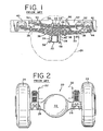
- axle housing 20 having a differential gear housing 22 at a central portion thereof is connected between vehicle wheels 24 positioned on opposite sides of a vehicle.
- Axle connection devices 26 which shall later be described in further detail, are welded to the front and rear faces of axle housing 20 in close proximity to each vehicle wheel 24. These connection devices 26 provide means for connecting a vehicle suspension 30 to the axle housing 20.
- the vehicle includes a frame 32 extending longitudinally down each side of the vehicle
- the vehicle suspension 30 is connected between the vehicle frame 32 and the axle housing 20 to suspend the vehicle body (not shown) above the vehicle wheels 24.
- the vehicle suspension 30 shown and described in US-A- 4,227,716 , and in Figs. 1-2 of the accompanying drawings, is generally known in the art as a Hotchkiss-type suspension.
- the suspension includes a main multi-leaf leaf spring pack 34 and an auxiliary multi-leaf leaf spring pack 36.
- the leaf springs that form the main leaf spring pack 34 are bundled together by a series of ties 38.
- the proximal end of the main leaf spring pack 34 is pivotally connected to a hanger 40, which in turn is fixedly mounted to the vehicle frame 32.
- the distal end of the main leaf spring pack 34 is connected to another hanger 42, which is also mounted to the vehicle frame 32.
- the distal end is connected to hanger 42 through a shackle 44 that permits the distal end to move during deflection of the main leaf spring pack.
- the central portion of the main leaf spring pack 34 is seated on axle seating 46.
- the auxiliary leaf spring pack 36 is seated on, and separated from the main leaf spring pack 34 by, a spacer 48.
- the leaf springs that form the auxiliary leaf spring pack 36 are bundled together by ties 50.
- the auxiliary leaf spring pack 36 is inactive.
- brackets 52 which are fixedly mounted to frame 32. This, in turn, will cause auxiliary leaf spring pack 36 to deflect during heavy vehicle load conditions
- Figs. 3-5 illustrate the axle connection devices 26 shown and described in US-A- 4,227,716 .
- these devices include a baseplate 60 having circular ends 62 and a relatively short and narrow waist 64 dividing the ends.
- the shape of baseplate 60 is similar to the symbol used to identify the mathematical concept of infinity. This shape permits the welds that connect the baseplate to the axle housing to withstand the forces exerted upon it during torsion of the axle housing.
- a horizontal support 65 projects outwardly from baseplate 60.
- Horizontal support 65 includes a relatively flat and horizontally projecting upper plane surface 66 and a relatively flat and horizontally projecting lower plane surface 67
- Upper surface 66 is generally parallel with lower surface 67.
- Horizontal support 65 also includes a waist 68 correspondingly positioned with waist 64 of baseplate 60 to divide the support 65 into two portions, each having a bore 70 extending straight through it. Bores 70 accommodate the threaded ends of U-bolts 54 when the leaf spring packs 34, 36 are connected to the axle housing 20.
- Each axle connection device 26 is welded to the axle housing 20 by way of a continuous weld 72 formed along the edge of baseplate 60 and extending about its entire perimeter.
- each vehicle make and model typically has its own set of pinion angles for each of its axles.
- the set of pinion angles used for one vehicle is typically not the same as used for another.
- the pinion angle used for one axle of a vehicle is typically not the same as used for another axle of that vehicle. All of this considered, it will be appreciated by those skilled in the art that axle housings typically are not positioned so that they extend straight up and down. Rather, they are rotated to an extent to accommodate the required pinion angle.
- axle connection devices With the construction of the aforementioned axle connection devices, it was often necessary to use additional parts and components to attach the vehicle suspension to the axle housing. These additional parts and components were required in order to accommodate the pinion angle. Such additional parts and components might, for instance, be uniquely designed shims or washers. Use of these additional parts and components added weight and expense to the suspension system, and required additional worker time and expense to design these components and to position, assemble and service them while the suspension system is connected to the axle housing.
- axle housings are ordinarily constructed in two halves that are fused or welded together. Often, the two axle housing halves have at least a slight mismatch, and use of the above-described axle connection devices required use of additional parts and components to accommodate this mismatch. Again, this added considerable weight and expense to the suspension system design, and required additional worker time and expense to design these components and to position, assemble and service them while the suspension system is connected to the axle housing.
- US-A-5950971 shows a bracket for mounting suspension members on top of a square-section axle housing.
- the bracket straddles the top of the axle housing, and each of its downwardly-extending side members is welded to the face of the housing.
- US-A-5921570 like US-A-4227716 , discloses horizontally-projecting supports fixed to the opposite faces of the axle housing and having bores to accommodate the ends of U-bolts.
- the supports with the bores are formed on and project from the downwardly-extending side flanges of a saddle bracket element which straddles the top of the axle housing, with a single weld for each of the side portions.
- US-A-3437333 shows a top axle clamp member with side recesses for the passage of U-bolts, and side portions extending down most of the height of the housing wall. Each side portion has an oval opening, around the edge of which a weld is run to secure the side portion to the axle housing wall.
- US-A-3386724 discloses a similar arrangement with straddling clamp members, the side portions having circular holes around which the welds are made.
- Preferred aims herein include the following. It is desirable to reduce the weight of vehicles that include welded axle connection devices.
- the preferred axle connection device used in the invention includes a generally flat baseplate having curvilinear ends separated by a relatively long and narrow waist. Each end includes a curvilinear side rim and two rounded corners from which the rim of the baseplate smoothly tapers towards the waist.
- the device also includes a generally horizontally projecting plane having a waist aligned with the waist of the baseplate to divide the plane into two distinct portions.
- the plane also has two supporting sidewalls. Both sidewalls extend from just inside the rounded corners of a respective end of the baseplate and taper towards associated corners of the horizontally projecting plane.
- Each portion of the plane includes a generally rounded boss extending from the plane. A slot extending from the intersection of the baseplate and the plane is incorporated in each boss to allow a connection bolt to pass through the device.
- the construction of the device permits it to accommodate varying pinion angles and axle housing mismatch.
- the present invention is directed to a method of welding an axle connection device to a face of an axle housing, as defined in claim 1.
- the method includes forming two continuous welds along both longitudinal edges of the device.
- Each weld begins longitudinally inward of one of the rounded corners of the device, preferably one of the rounded corners positioned closest to the spindle end of the axle.
- the weld is formed such that it extends longitudinally outwardly towards that rounded corner to a weld end, which is positioned longitudinally inward of that corner.
- the weld is then turned back on itself and extends longitudinally inwardly along the tapering slope of the end of the device towards the waist portion thereof to form a double-pass weld at its end.
- the weld then extends through the waist portion, then longitudinally outwardly along the tapering slope of the opposite end of the device to a point just shy of the rounded corner at that end. At that point, the weld is again turned back on itself to form a double-pass weld at its end. The weld is then terminated. Another continuous weld is made in like fashion along the opposing longitudinal edge of the device. Under this method, substantially less weld is used and the weld lines do not traverse over, along and/or around the rounded corners of the device. As a result, the axle housing (as opposed to the weld runs) primarily absorbs any torsional loading.
- axle connection device 100 is shown.
- Axle connection device 100 is similar to axle connection device 26, described above, to the extent that it permits the connection of a vehicle suspension system to an axle housing.
- axle connection device 100 could replace the axle connection devices 26 and be mounted to opposite faces of axle housing 20 shown in FIG. 1 . So mounted, it would permit vehicle suspension 30 to be connected to axle housing 20.
- FIG. 10 two axle connection devices 100 are shown as being mounted to the front and rear faces of an axle housing 102.
- FIG. 10 further illustrates a longitudinally extending vehicle frame 104 that is sprung above a vehicle axle by a vehicle suspension 106.
- the vehicle suspension 106 shown in FIG. 10 is generally referred to as a trailing arm suspension by those skilled in the art.
- one end of a Z-shaped spring 108 is pivotally connected to a hanger 110, which, in turn, is mounted to vehicle frame 104.
- the opposite end ofZ-shaped spring 108 is connected to an air spring 112, which is connected to the vehicle frame 104 through a mounting bracket 114.
- shock absorber 116 One end of a shock absorber 116 is attached to a mounting bracket 118, which is mounted to vehicle frame 104. The other end of the shock absorber 116 is received within a port included in a shock mounting device 120, which is attached to the axle housing 102 by an axle attachment assembly 122.
- Axle attachment assembly 122 includes a guide plate 124, an axle seat 126, two U-bolts 128, fasteners 130, and two axle connection devices 100.
- the U-bolts 128 connect the active components of vehicle suspension 106 with the axle housing 102.
- the axle housing 102 is shown as being rotated slightly in FIG. 10 to accommodate the pinion angle.
- axle connection device 100 which has built-in features to accommodate the pinion angle, provides substantial benefits beyond those derived from the axle connection devices 26 illustrated in FIGS. 1-5 .
- the axle connection device 100 is designed to be welded to opposing faces of the axle housing 102.
- the axle connection device 100 includes a generally flat baseplate 132 having curvilinear ends 134 separated by a relatively long and narrow waist 136. In this configuration, axle connection device 100 resembles a dog bone-like shape.
- Each end 134 includes a curvilinear side rim 138 and two rounded corners 140, 142 from which the rim of the baseplate smoothly tapers towards waist 136.
- the axle connection device 100 also includes a horizontally projecting plane 144 having a waist 146 correspondingly positioned with the waist 136 of baseplate 132. Waist 146 divides plane 144 into two distinct portions. Plane 144 includes two supporting sidewalls 148. Sidewalls 148 extend from just laterally inward of the rounded corners 140, 142 of a respective end of the baseplate 132 and taper towards the corresponding corners of horizontally projecting plane 144.
- Each portion of plane 144 includes a generally rounded boss 150 extending from the plane.
- a slot 152 extending from the intersection of baseplate 132 and plane 144 is indexed with and incorporated in each boss 150 to allow a connection bolt, such as the aforementioned U-bolts 128, to pass through the axle connection device 100.
- the geometry and construction of axle connection device 100, and particularly its bosses 150, permit the device to accommodate varying pinion angles and axle housing mismatch.
- axle connection device 100 is connected to axle housing 102 such that one base end portion is closer to the spindle end 163A of the axle housing while the other base end portion is closer to the bowl end 163B of the axle housing.
- Weld runs 160, 162 preferably extend over opposite longitudinal edges of the rim of baseplate 132. Unlike the continuous weld run shown in FIG. 3 , weld runs 160, 162 do not traverse about the entire perimeter of baseplate 132. This reduction of metal is a result of the unique weld technique described below and the geometry and construction of axle connection device 100.
- weld 160 is preferably formed by beginning the welding process at a point longitudinally inwardly of one of the rounded corners positioned at the top longitudinal edge of device 100. It will be understood, however, that the first weld run could be along the bottom longitudinal edge of device 100.
- weld 160 begins closest to rounded corner 140, as that corner is closest to the spindle end 163A of the axle housing 102. From its beginning point 164, weld 160 is formed such that it extends longitudinally outwardly towards rounded corner 140 to a weld end 166, which is positioned longitudinally inward of corner 140. Weld 160 is then turned back onto itself and extends down the tapering slope of device 100 towards waist 136 to form a double-pass weld between beginning point 164 and weld end 166.
- Weld 160 then extends through waist 136, upward along the tapering slope of the opposite end of device 100, and longitudinally outward towards rounded corner 142. Just shy of rounded corner 142, weld 160 is again turned back on itself at weld end 168 and continues to a weld termination point 170. As a result, weld 160 forms another double-pass weld between weld end 168 and termination point 170.
- Weld 162 is formed in a similar fashion along the bottom longitudinal edge of device 100.
- weld 162 preferably begins closest to rounded corner 140, as that corner is closest to the spindle end 163A of the axle housing 102. From its beginning point 172, weld 162 is formed such that it extends longitudinally outwardly towards rounded corner 140 to a weld end 174, which is positioned longitudinally inward of corner 140. Weld 162 is then turned back onto itself and extends down the tapering slope of device 100 towards waist 136 to form a double-pass weld between beginning point 172 and weld end 174.
- Weld 162 then extends through waist 136, upward along the tapering slope of the opposite end of device 100, and longitudinally outward towards rounded corner 142. Just shy of rounded corner 142, weld 162 is again turned back on itself at weld end 176 and continues to a weld termination point 178. As a result, weld 162 forms another double-pass weld between weld end 176 and termination point 178.
- the axle housing 102 primarily absorbs any torsional loading. As a result, the extent to which the weld runs 160, 162 are subjected to torsional loading is minimized, thereby reducing the possibility of cracking.
Landscapes
- Engineering & Computer Science (AREA)
- Mechanical Engineering (AREA)
- Vehicle Body Suspensions (AREA)
- Butt Welding And Welding Of Specific Article (AREA)
- Heat Treatment Of Articles (AREA)
Claims (8)
- Verfahren zum Schweißen einer Achsverbindungsvorrichtung (100) an ein Achsgehäuse (102), wobei die Achsverbindungsvorrichtung eine Basis (132) aufweist, die einen ersten und einen zweiten Basisendabschnitt (134) umfasst, die durch ein Basismittelstück (136) voneinander getrennt sind, wobei der erste Basisendabschnitt einen ersten sich in Querrichtung erstreckenden Seitenrand (138), eine erste und eine zweite sich in Längsrichtung erstreckende Kante, die an gegenüberliegenden Seiten der Vorrichtung angeordnet sind, und eine erste und zweite Ecke (140) beinhaltet, die zwischen dem ersten Seitenrand (138) und der ersten und der zweiten sich in Längsrichtung erstreckenden Kante und an diese angrenzend angeordnet sind, und der zweite Basisendabschnitt (134) einen zweiten sich in Querrichtung erstreckenden Seitenrand (138), eine dritte und vierte sich in Längsrichtung erstreckende Kante, die an gegenüberliegenden Seiten der Vorrichtung angeordnet sind, und eine dritte und vierte Ecke (142) beinhaltet, die zwischen dem zweiten Seitenrand (138) und der dritten und vierten sich in Längsrichtung erstreckenden Kante und an diese angrenzend angeordnet sind;
wobei das Schweißverfahren durch folgende Schritte gekennzeichnet ist:Beginnen eines ersten Schweißdurchlaufes (160) an einem ersten Schweißdurchlaufausgangspunkt (164), der entlang der ersten sich in Längsrichtung erstreckenden Kante des ersten Basisendabschnitts (134) angeordnet ist;Fortführen des ersten Schweißdurchlaufes (160) nach außen hin entlang der ersten sich in Längsrichtung erstreckenden Kante in Richtung der ersten Ecke (140) zu einem ersten Endpunkt (166) des ersten Schweißdurchlaufes, der in Längsrichtung von der ersten Ecke (140) nach innen versetzt angeordnet ist;Rückführen des ersten Schweißdurchlaufes (160) auf sich selbst bei dem ersten Endpunkt (166) des ersten Schweißverlaufes und Ausdehnen desselben entlang der ersten sich in Längsrichtung erstreckenden Kante zu dem ersten Schweißdurchlaufausgangspunkt zur Ausbildung eines ersten doppelt-durchfahrenen geschweißten Abschnitts des ersten Schweißdurchlaufes;Fortführen des ersten Schweißdurchlaufes (160) entlang der ersten sich in Längsrichtung erstreckenden Kante von dem ersten Schweißdurchlaufausgangspunkt (164) aus entlang dem Basismittelstück (136) und entlang der dritten sich in Längsrichtung erstreckenden Kante des zweiten Basisendabschnitts zu einem zweiten Endpunkt (168) des ersten Schweißdurchlaufes, der in Längsrichtung von der dritten Ecke (142) nach innen versetzt angeordnet ist;Rückführen des ersten Schweißdurchlaufes (160) auf sich selbst bei dem zweiten Endpunkt (168) des ersten Schweißverlaufes und Ausdehnen desselben entlang der dritten sich in Längsrichtung erstreckenden Kante zu einem ersten Schweißdurchlaufabschlusspunkt (170), der entlang der dritten sich in Längsrichtung erstreckenden Kante positioniert ist, zur Ausbildung eines zweiten doppelt-durchfahrenen geschweißten Abschnitts des ersten Schweißdurchlaufes (160);Beginnen eines zweiten Schweißdurchlaufes (162) an einem zweiten Schweißdurchlaufausgangspunkt (172), der entlang einer aus der zweiten und vierten sich in Längsrichtung erstreckenden Kante angeordnet ist;Fortführen des zweiten Schweißdurchlaufes (162) entlang der einen aus der zweiten und vierten sich in Längsrichtung erstreckenden Kante in Richtung (140) einer aus der zweiten und vierten Ecke (140, 142) zu einem ersten Endpunkt (174) des zweiten Schweißdurchlaufes, der von der einen (140) aus der zweiten und vierten Ecke in Längsrichtung nach innen versetzt angeordnet ist;Rückführen des zweiten Schweißdurchlaufes (162) auf sich selbst bei dem ersten Endpunkt (174) des zweiten Schweißverlaufes und Ausdehnen desselben entlang einer aus der zweiten und vierten sich in Längsrichtung erstreckenden Kante zu dem zweiten Schweißdurchlaufausgangspunkt (172) zur Ausbildung eines ersten doppelt-durchlaufenen geschweißten Abschnitts des zweiten Schweißdurchlaufes (162);Fortführen des zweiten Schweißdurchlaufes (162) entlang des einen aus der zweiten und vierten sich in Längsrichtung erstreckenden Kante von dem zweiten Schweißdurchlaufausgangspunkt (172) aus entlang dem Basismittelstück (136) und entlang der anderen der zweiten und der vierten sich in Längsrichtung erstreckenden Kante zu einem zweiten Endpunkt (176) der zweiten Schweißdurchlaufes, der in Längsrichtung von der anderen (142) der zweiten und vierten Ecke (140, 142) nach innen versetzt angeordnet ist;Rückführen des zweiten Schweißdurchlaufes (162) auf sich selbst bei dem zweiten Endpunkt (176) des zweiten Schweißverlaufes und Ausdehnen desselben entlang der anderen aus der zweiten und vierten sich in Längsrichtung erstreckenden Kante zu einem zweiten Schweißdurchlaufabschlusspunkt (173), der entlang der anderen aus der zweiten und vierten sich in Längsrichtung erstreckenden Kante angeordnet ist, zur Ausbildung eines zweiten doppelt-durchlaufenen geschweißten Abschnitts des zweiten Schweißdurchlaufes (162). - Verfahren nach Anspruch 1, worin die eine aus der zweiten und vierten sich in Längsrichtung erstreckenden Kante die zweite sich in Längsrichtung erstreckende Kante ist, die andere der zweiten und vierten sich in Längsrichtung erstreckende Kante die vierte sich in Längsrichtung erstreckende Kante ist, die eine aus der zweiten und der vierten Ecke die zweite Ecke (140) ist und die andere aus der zweiten und der vierten Ecke die vierte Ecke (142) ist.
- Verfahren nach Anspruch 1 oder 2, worin das Achsgehäuse (102) ein Spindelende (163A) und ein Schalenende (163B) umfasst und worin die Achsverbindungsvorrichtung (100) so an das Achsgehäuse geschweißt ist, dass das erste Basisende zu dem Spindelende näher als das zweite Basisende ist und das zweite Basisende zu dem Schalenende näher als das erste Basisende ist.
- Verfahren nach Anspruch 1, 2 oder 3, worin die erste und zweite sich in Längsrichtung erstreckende Kante entlang einer oberen Längskante der Achsverbindungsvorrichtung angeordnet sind und die zweite und vierte sich in Längsrichtung erstreckende Kante entlang einer unteren Längskante der Achsverbindungsvorrichtung angeordnet sind.
- Verfahren nach einem der Ansprüche 1 bis 4, worin der erste Schweißdurchgang (160) ein kontinuierlicher Schweißdurchgang ist und der zweite Schweißdurchgang (162) ein kontinuierlicher Schweißdurchgang ist.
- Achsverbindungsvorrichtung (100), die an ein Achsgehäuse (102) geschweißt ist, um das Verbinden eines Fahrzeugaufhängungssystems mit dem Achsgehäuse zu ermöglichen, wobei diese Folgendes umfasst:eine Basis (132) mit einem ersten und einem zweiten Basisendabschnitt (134), die durch einen zentral angeordneten zentralen Basisabschnitt (136) voneinander getrennt sind;wobei der erste Basis-Endabschnitt (134) einen ersten sich in Querrichtung erstreckenden Seitenrand (138), eine erste und zweite sich in Längsrichtung erstreckende Kante, die an gegenüberliegenden Seiten der Vorrichtung angeordnet sind, und eine erste und eine zweite Ecke (140) umfasst, die zwischen dem ersten Seitenrand (138) und der ersten und der zweiten Kante und an diese angrenzend angeordnet sind;
wobei der zweite Basis-Endabschnitt (134) einen zweiten sich in Querrichtung erstreckenden Seitenrand (138), eine dritte und vierte sich in Längsrichtung erstreckende Kante, die an gegenüberliegenden Seiten der Vorrichtung angeordnet sind, und eine dritte und eine vierte Ecke (142) umfasst, die zwischen dem zweiten Seitenrand (138) und der dritten und vierten Kante und an diese angrenzend angeordnet sind;
eine Ebene (144), die von der Basis (132) vorsteht, wobei diese Ebene einen zentralen Ebenenabschnitt (146) und einen ersten und zweiten Ebenenendabschnitt aufweist, die durch den zentralen Ebenenabschnitt voneinander getrennt und an gegenüberliegenden Seiten davon angeordnet sind;
wobei der erste Ebenenendabschnitt eine erste Öffnung (152) aufweist, die sich durch diesen hindurch erstreckt;
und wobei der zweite Ebenenendabschnitt eine zweite Öffnung (152) aufweist, die sich durch diesen hindurch erstreckt;
dadurch gekennzeichnet, dass die Vorrichtung (100) durch folgende Schweißdurchläufe an das Gehäuse (102) geschweißt ist:ein erster Schweißdurchlauf (160), der sich entlang von Abschnitten der ersten und dritten sich in Längsrichtung erstreckenden Kante zwischen einem ersten Endpunkt (166) des ersten Schweißdurchlaufes, der entlang der ersten sich in Längsrichtung erstreckenden Kante von der ersten Ecke (140) aus nach innen versetzt angeordnet ist, und einem zweiten Endpunkt (168) des ersten Schweißdurchlaufes verläuft, der entlang der dritten sich in Längsrichtung erstreckenden Kante von der dritten Ecke (142) aus nach innen versetzt angeordnet ist, undein zweiter Schweißdurchlauf (162), der sich zwischen einem ersten Endpunkt (174) des zweiten Schweißdurchlaufes, der entlang der zweiten sich in Längsrichtung erstreckenden Kante von der zweiten Ecke (140) aus nach innen versetzt angeordnet ist, und einem zweiten Endpunkt (176) für den zweiten Schweißdurchlauf verläuft, der entlang der vierten sich in Längsrichtung erstreckenden Kante von der vierten Ecke (142) aus nach innen versetzt angeordnet ist. - An ein Achsgehäuse geschweißte Achsverbindungsvorrichtung nach Anspruch 6, worin der erste Schweißdurchlauf (160) einen doppelt-durchlaufenen geschweißten Abschnitt umfasst und der zweite Schweißdurchlauf (162) einen doppelt-durchlaufenen geschweißten Abschnitt umfasst.
- An ein Achsgehäuse geschweißte Achsverbindungsvorrichtung nach Anspruch 7, worin jede der ersten und zweiten Schweißdurchläufe (160, 162) zwei doppelt-durchlaufene geschweißte Abschnitte aufweist, und zwar einen doppelt-durchlaufenen geschweißten Abschnitt, der sich zwischen einem der Schweißdurchlaufsendpunkte (166, 174) und einem entsprechenden Schweißdurchlaufsausgangspunkt (164, 172) in Längsrichtung in Bezug auf einen der Endpunkte nach innen versetzt erstreckt, und den anderen doppelt-durchlaufenen geschweißten Abschnitt, der sich zwischen dem anderen der Schweißdurchlaufsendpunkte (168, 176) und einem entsprechenden Schweißdurchlaufabschlusspunkt (170, 173) in Längsrichtung in Bezug auf den anderen der Endpunkte nach innen versetzt erstreckt.
Applications Claiming Priority (2)
| Application Number | Priority Date | Filing Date | Title |
|---|---|---|---|
| US09/535,668 US6641156B1 (en) | 2000-02-22 | 2000-02-22 | Device for connecting suspension system components for axle housing |
| EP01910755A EP1257429B1 (de) | 2000-02-22 | 2001-02-15 | Vorrichtung zum verbinden von bauteilen eines radaufhängungssystems mit einem achsgehäuse |
Related Parent Applications (1)
| Application Number | Title | Priority Date | Filing Date |
|---|---|---|---|
| EP01910755A Division EP1257429B1 (de) | 2000-02-22 | 2001-02-15 | Vorrichtung zum verbinden von bauteilen eines radaufhängungssystems mit einem achsgehäuse |
Publications (4)
| Publication Number | Publication Date |
|---|---|
| EP1640191A2 EP1640191A2 (de) | 2006-03-29 |
| EP1640191A3 EP1640191A3 (de) | 2006-04-19 |
| EP1640191B1 true EP1640191B1 (de) | 2008-08-06 |
| EP1640191B8 EP1640191B8 (de) | 2008-10-15 |
Family
ID=24135243
Family Applications (2)
| Application Number | Title | Priority Date | Filing Date |
|---|---|---|---|
| EP05023828A Expired - Lifetime EP1640191B8 (de) | 2000-02-22 | 2001-02-15 | Schweissmethode für Achsverbindung und so hergestellte Achsaufhängung |
| EP01910755A Expired - Lifetime EP1257429B1 (de) | 2000-02-22 | 2001-02-15 | Vorrichtung zum verbinden von bauteilen eines radaufhängungssystems mit einem achsgehäuse |
Family Applications After (1)
| Application Number | Title | Priority Date | Filing Date |
|---|---|---|---|
| EP01910755A Expired - Lifetime EP1257429B1 (de) | 2000-02-22 | 2001-02-15 | Vorrichtung zum verbinden von bauteilen eines radaufhängungssystems mit einem achsgehäuse |
Country Status (12)
| Country | Link |
|---|---|
| US (1) | US6641156B1 (de) |
| EP (2) | EP1640191B8 (de) |
| KR (1) | KR100754754B1 (de) |
| AT (2) | ATE343487T1 (de) |
| AU (2) | AU3832801A (de) |
| BR (1) | BR0108596B1 (de) |
| CA (2) | CA2400927C (de) |
| DE (2) | DE60124076T2 (de) |
| ES (2) | ES2313184T3 (de) |
| MX (1) | MXPA02008165A (de) |
| NZ (1) | NZ521002A (de) |
| WO (1) | WO2001062527A1 (de) |
Cited By (1)
| Publication number | Priority date | Publication date | Assignee | Title |
|---|---|---|---|---|
| CN101362248B (zh) * | 2008-09-05 | 2011-02-02 | 江西江铃底盘股份有限公司 | 一种桥壳本体总成y型焊缝的焊接设备及焊接工艺 |
Families Citing this family (9)
| Publication number | Priority date | Publication date | Assignee | Title |
|---|---|---|---|---|
| US7445220B2 (en) | 2004-02-06 | 2008-11-04 | Daimler Trucks North America Llc | Vehicle axle apparatus |
| US20060103103A1 (en) * | 2004-11-12 | 2006-05-18 | Land Jonathan L | Lightweight, low part-count, suspension system for wheeled vehicles |
| US7331590B2 (en) * | 2004-11-30 | 2008-02-19 | Trw Automotive U.S. Llc | Commercial vehicle suspension assembly |
| US20060113741A1 (en) | 2004-12-01 | 2006-06-01 | Chalin Thomas N | Suspension system having high strength arm to axle connection |
| US7347435B2 (en) * | 2005-01-14 | 2008-03-25 | Watson & Chalin Manufacturing, Inc. | Suspension system having reduced weight arm construction |
| DE102010015951A1 (de) * | 2010-03-12 | 2011-09-15 | Muhr Und Bender Kg | Blattfeder für Kraftfahrzeuge |
| WO2012078031A1 (en) * | 2010-12-09 | 2012-06-14 | Vdl Weweler B.V. | Vehicle axle suspension, and vehicle comprising such vehicle axle suspension |
| CN103692138B (zh) * | 2013-12-29 | 2015-09-30 | 长城汽车股份有限公司 | 一种汽车后桥壳总成工件焊装定位夹具 |
| CN109703311A (zh) * | 2017-10-26 | 2019-05-03 | 东风汽车悬架弹簧有限公司 | 一种用于汽车安装悬架空气弹簧的“z”字形导向臂 |
Family Cites Families (22)
| Publication number | Priority date | Publication date | Assignee | Title |
|---|---|---|---|---|
| US3386724A (en) * | 1965-11-04 | 1968-06-04 | Fruehauf Corp | Vehicle construction spring-to-axle mounting |
| US3437333A (en) * | 1966-10-24 | 1969-04-08 | North American Rockwell | Spring seat |
| US3630541A (en) * | 1970-06-11 | 1971-12-28 | Int Harvester Co | Vehicle axle suspension |
| US3891197A (en) * | 1973-10-15 | 1975-06-24 | Gus L Poulos | Single leaf spring |
| US3913937A (en) * | 1974-07-03 | 1975-10-21 | Dura Corp | Universal axle pad and clamp assemblies for vehicle suspensions |
| US4033606A (en) * | 1975-08-06 | 1977-07-05 | Reyco Industries, Inc. | Vehicle tandem suspensions |
| SE424292B (sv) | 1977-12-22 | 1982-07-12 | Saab Scania Ab | Anordning for infestning av ett fjedersystem till en axelbrygga |
| US4545452A (en) * | 1983-09-26 | 1985-10-08 | Caterpillar Tractor Co. | Axle housing mounting bracket |
| US4801129A (en) * | 1987-01-20 | 1989-01-31 | Ford Motor Company | Leaf spring clamp with attachment means |
| US5046756A (en) * | 1989-06-21 | 1991-09-10 | Hertrick Bradley J | Wheel axle adjustment assembly |
| DE69310779T2 (de) * | 1992-02-01 | 1997-12-18 | Mitsubishi Motors Corp | Hinterradlenkeinrichtung |
| DE4221996C2 (de) * | 1992-07-04 | 1996-09-12 | Man Nutzfahrzeuge Ag | Doppelachsaggregat bei Lastkraftwagen |
| US5328159A (en) * | 1992-08-18 | 1994-07-12 | Dana Corporation | Axle housing attachment assembly |
| US5346247A (en) * | 1993-05-14 | 1994-09-13 | Reyco Industries, Inc. | Truck air ride suspension |
| US5476251A (en) * | 1994-08-15 | 1995-12-19 | Dana Corporation | Axle bracket providing improved support |
| US5950971A (en) * | 1996-06-28 | 1999-09-14 | The Boler Company | Assembly for and method of mounting a suspension member to an axle housing |
| US5921570A (en) * | 1996-11-21 | 1999-07-13 | The Boler Company | Weld-on axle bracket with U-bolt connection |
| US6082750A (en) * | 1998-02-11 | 2000-07-04 | Navistar International Transportation Corp | Closed joint leaf spring mounting assembly |
| US6032967A (en) * | 1998-02-18 | 2000-03-07 | Dana Canada, Inc. | Axle and suspension connection assembly and method |
| US6129369A (en) * | 1998-03-18 | 2000-10-10 | The Boler Company. | Leaf spring distal end portion single rotation point attachment part |
| US6015158A (en) * | 1998-06-24 | 2000-01-18 | Timbren Industries Inc. | Heavy duty truck suspension |
| JP4414587B2 (ja) * | 2000-11-20 | 2010-02-10 | プレス工業株式会社 | アクスルハウジング用スプリングシートブラケット |
-
2000
- 2000-02-22 US US09/535,668 patent/US6641156B1/en not_active Expired - Lifetime
-
2001
- 2001-02-15 BR BRPI0108596-4A patent/BR0108596B1/pt not_active IP Right Cessation
- 2001-02-15 AT AT01910755T patent/ATE343487T1/de not_active IP Right Cessation
- 2001-02-15 EP EP05023828A patent/EP1640191B8/de not_active Expired - Lifetime
- 2001-02-15 CA CA2400927A patent/CA2400927C/en not_active Expired - Fee Related
- 2001-02-15 MX MXPA02008165A patent/MXPA02008165A/es active IP Right Grant
- 2001-02-15 AU AU3832801A patent/AU3832801A/xx active Pending
- 2001-02-15 CA CA2634331A patent/CA2634331C/en not_active Expired - Fee Related
- 2001-02-15 DE DE60124076T patent/DE60124076T2/de not_active Expired - Lifetime
- 2001-02-15 KR KR1020027010970A patent/KR100754754B1/ko not_active Expired - Fee Related
- 2001-02-15 DE DE60135259T patent/DE60135259D1/de not_active Expired - Lifetime
- 2001-02-15 ES ES05023828T patent/ES2313184T3/es not_active Expired - Lifetime
- 2001-02-15 ES ES01910755T patent/ES2275655T3/es not_active Expired - Lifetime
- 2001-02-15 NZ NZ521002A patent/NZ521002A/en unknown
- 2001-02-15 AT AT05023828T patent/ATE403560T1/de not_active IP Right Cessation
- 2001-02-15 AU AU2001238328A patent/AU2001238328B2/en not_active Ceased
- 2001-02-15 EP EP01910755A patent/EP1257429B1/de not_active Expired - Lifetime
- 2001-02-15 WO PCT/US2001/004889 patent/WO2001062527A1/en not_active Ceased
Cited By (1)
| Publication number | Priority date | Publication date | Assignee | Title |
|---|---|---|---|---|
| CN101362248B (zh) * | 2008-09-05 | 2011-02-02 | 江西江铃底盘股份有限公司 | 一种桥壳本体总成y型焊缝的焊接设备及焊接工艺 |
Also Published As
| Publication number | Publication date |
|---|---|
| WO2001062527A1 (en) | 2001-08-30 |
| ATE343487T1 (de) | 2006-11-15 |
| KR20030077942A (ko) | 2003-10-04 |
| DE60124076T2 (de) | 2007-05-31 |
| DE60135259D1 (de) | 2008-09-18 |
| CA2400927C (en) | 2011-11-29 |
| CA2634331A1 (en) | 2001-08-30 |
| US6641156B1 (en) | 2003-11-04 |
| ES2275655T3 (es) | 2007-06-16 |
| EP1640191A3 (de) | 2006-04-19 |
| EP1257429A4 (de) | 2004-06-16 |
| MXPA02008165A (es) | 2003-02-27 |
| ATE403560T1 (de) | 2008-08-15 |
| AU2001238328B2 (en) | 2004-04-08 |
| EP1640191A2 (de) | 2006-03-29 |
| EP1257429A1 (de) | 2002-11-20 |
| KR100754754B1 (ko) | 2007-09-04 |
| BR0108596B1 (pt) | 2010-10-19 |
| EP1257429B1 (de) | 2006-10-25 |
| AU3832801A (en) | 2001-09-03 |
| DE60124076D1 (de) | 2006-12-07 |
| ES2313184T3 (es) | 2009-03-01 |
| BR0108596A (pt) | 2003-05-13 |
| NZ521002A (en) | 2004-06-25 |
| EP1640191B8 (de) | 2008-10-15 |
| CA2400927A1 (en) | 2001-08-30 |
| CA2634331C (en) | 2010-09-28 |
Similar Documents
| Publication | Publication Date | Title |
|---|---|---|
| US9493048B2 (en) | Motor vehicle axle suspension with longitudinal leaf spring | |
| AU716460B2 (en) | Means for and method of mounting a suspension member to an axle housing | |
| US5112078A (en) | Axle mounting assembly | |
| EP1693592B1 (de) | Blattfedereinrichtung mit ganzem Blatt-Blatt-Federbauelement und halbem Blatt-Blatt-Federbauelement | |
| US4165099A (en) | Rear suspension apparatus for a motor vehicle | |
| US4165098A (en) | Rear suspension apparatus for a motor vehicle | |
| US6209895B1 (en) | Axle suspension system for a wheeled vehicle | |
| US7926836B2 (en) | Elastomeric spring vehicle suspension | |
| EP0190725A2 (de) | Aufhängung für Kraftfahrzeuge | |
| US4998749A (en) | Suspension for smooth ride with good handling control of heavy load vehicles | |
| EP1640191B1 (de) | Schweissmethode für Achsverbindung und so hergestellte Achsaufhängung | |
| US6733020B2 (en) | Suspension trailing arm | |
| CA2330874A1 (en) | Vehicle trailer frame cross member/suspension assembly mount | |
| AU2001238328A1 (en) | Device for connecting suspension system components to axle housing | |
| US5265907A (en) | Auxiliary suspension assembly for Ford "F" and "E" series trucks | |
| US6626454B1 (en) | Trailer suspension | |
| WO1994005520A1 (en) | Independent wheel suspension | |
| US6676143B2 (en) | Modular suspension arm assembly | |
| CN223456763U (zh) | 一种双臂式独立悬架 | |
| CA1316549C (en) | Multi-axle vehicle suspension | |
| KR19980038315U (ko) | 현가장치의 스트러트와 너클 체결구조 |
Legal Events
| Date | Code | Title | Description |
|---|---|---|---|
| PUAI | Public reference made under article 153(3) epc to a published international application that has entered the european phase |
Free format text: ORIGINAL CODE: 0009012 |
|
| PUAL | Search report despatched |
Free format text: ORIGINAL CODE: 0009013 |
|
| AC | Divisional application: reference to earlier application |
Ref document number: 1257429 Country of ref document: EP Kind code of ref document: P |
|
| AK | Designated contracting states |
Kind code of ref document: A2 Designated state(s): AT BE CH CY DE DK ES FI FR GB GR IE IT LI LU MC NL PT SE TR |
|
| AK | Designated contracting states |
Kind code of ref document: A3 Designated state(s): AT BE CH CY DE DK ES FI FR GB GR IE IT LI LU MC NL PT SE TR |
|
| RIN1 | Information on inventor provided before grant (corrected) |
Inventor name: BRANNIGAN, MICHAEL Inventor name: BARLAS, SERGE A. |
|
| 17P | Request for examination filed |
Effective date: 20061017 |
|
| AKX | Designation fees paid |
Designated state(s): AT BE CH CY DE DK ES FI FR GB GR IE IT LI LU MC NL PT SE TR |
|
| 17Q | First examination report despatched |
Effective date: 20061218 |
|
| GRAP | Despatch of communication of intention to grant a patent |
Free format text: ORIGINAL CODE: EPIDOSNIGR1 |
|
| GRAS | Grant fee paid |
Free format text: ORIGINAL CODE: EPIDOSNIGR3 |
|
| GRAA | (expected) grant |
Free format text: ORIGINAL CODE: 0009210 |
|
| AC | Divisional application: reference to earlier application |
Ref document number: 1257429 Country of ref document: EP Kind code of ref document: P |
|
| AK | Designated contracting states |
Kind code of ref document: B1 Designated state(s): AT BE CH CY DE DK ES FI FR GB GR IE IT LI LU MC NL PT SE TR |
|
| REG | Reference to a national code |
Ref country code: GB Ref legal event code: FG4D |
|
| REG | Reference to a national code |
Ref country code: CH Ref legal event code: EP |
|
| RBV | Designated contracting states (corrected) |
Designated state(s): BE CH DE ES FR GB IT LI NL SE TR |
|
| REG | Reference to a national code |
Ref country code: IE Ref legal event code: FG4D |
|
| REF | Corresponds to: |
Ref document number: 60135259 Country of ref document: DE Date of ref document: 20080918 Kind code of ref document: P |
|
| REG | Reference to a national code |
Ref country code: SE Ref legal event code: TRGR |
|
| REG | Reference to a national code |
Ref country code: ES Ref legal event code: FG2A Ref document number: 2313184 Country of ref document: ES Kind code of ref document: T3 |
|
| PLBE | No opposition filed within time limit |
Free format text: ORIGINAL CODE: 0009261 |
|
| STAA | Information on the status of an ep patent application or granted ep patent |
Free format text: STATUS: NO OPPOSITION FILED WITHIN TIME LIMIT |
|
| 26N | No opposition filed |
Effective date: 20090507 |
|
| REG | Reference to a national code |
Ref country code: IE Ref legal event code: MM4A |
|
| PGFP | Annual fee paid to national office [announced via postgrant information from national office to epo] |
Ref country code: CH Payment date: 20100224 Year of fee payment: 10 Ref country code: ES Payment date: 20100225 Year of fee payment: 10 |
|
| PGFP | Annual fee paid to national office [announced via postgrant information from national office to epo] |
Ref country code: FR Payment date: 20100303 Year of fee payment: 10 Ref country code: IT Payment date: 20100223 Year of fee payment: 10 |
|
| PGFP | Annual fee paid to national office [announced via postgrant information from national office to epo] |
Ref country code: GB Payment date: 20100224 Year of fee payment: 10 Ref country code: DE Payment date: 20100226 Year of fee payment: 10 Ref country code: BE Payment date: 20100223 Year of fee payment: 10 Ref country code: TR Payment date: 20100205 Year of fee payment: 10 |
|
| PGFP | Annual fee paid to national office [announced via postgrant information from national office to epo] |
Ref country code: NL Payment date: 20100223 Year of fee payment: 10 |
|
| PGFP | Annual fee paid to national office [announced via postgrant information from national office to epo] |
Ref country code: SE Payment date: 20100226 Year of fee payment: 10 |
|
| BERE | Be: lapsed |
Owner name: HENDRICKSON INTERNATIONAL CORP. Effective date: 20110228 |
|
| REG | Reference to a national code |
Ref country code: NL Ref legal event code: V1 Effective date: 20110901 |
|
| REG | Reference to a national code |
Ref country code: CH Ref legal event code: PL |
|
| REG | Reference to a national code |
Ref country code: SE Ref legal event code: EUG |
|
| GBPC | Gb: european patent ceased through non-payment of renewal fee |
Effective date: 20110215 |
|
| PG25 | Lapsed in a contracting state [announced via postgrant information from national office to epo] |
Ref country code: CH Free format text: LAPSE BECAUSE OF NON-PAYMENT OF DUE FEES Effective date: 20110228 Ref country code: LI Free format text: LAPSE BECAUSE OF NON-PAYMENT OF DUE FEES Effective date: 20110228 |
|
| REG | Reference to a national code |
Ref country code: FR Ref legal event code: ST Effective date: 20111102 |
|
| PG25 | Lapsed in a contracting state [announced via postgrant information from national office to epo] |
Ref country code: BE Free format text: LAPSE BECAUSE OF NON-PAYMENT OF DUE FEES Effective date: 20110228 |
|
| PG25 | Lapsed in a contracting state [announced via postgrant information from national office to epo] |
Ref country code: NL Free format text: LAPSE BECAUSE OF NON-PAYMENT OF DUE FEES Effective date: 20110901 Ref country code: IT Free format text: LAPSE BECAUSE OF NON-PAYMENT OF DUE FEES Effective date: 20110215 |
|
| REG | Reference to a national code |
Ref country code: DE Ref legal event code: R119 Ref document number: 60135259 Country of ref document: DE Effective date: 20110901 |
|
| PG25 | Lapsed in a contracting state [announced via postgrant information from national office to epo] |
Ref country code: FR Free format text: LAPSE BECAUSE OF NON-PAYMENT OF DUE FEES Effective date: 20110228 |
|
| PG25 | Lapsed in a contracting state [announced via postgrant information from national office to epo] |
Ref country code: GB Free format text: LAPSE BECAUSE OF NON-PAYMENT OF DUE FEES Effective date: 20110215 |
|
| REG | Reference to a national code |
Ref country code: ES Ref legal event code: FD2A Effective date: 20120411 |
|
| PG25 | Lapsed in a contracting state [announced via postgrant information from national office to epo] |
Ref country code: ES Free format text: LAPSE BECAUSE OF NON-PAYMENT OF DUE FEES Effective date: 20110216 |
|
| PG25 | Lapsed in a contracting state [announced via postgrant information from national office to epo] |
Ref country code: SE Free format text: LAPSE BECAUSE OF NON-PAYMENT OF DUE FEES Effective date: 20110216 |
|
| PG25 | Lapsed in a contracting state [announced via postgrant information from national office to epo] |
Ref country code: DE Free format text: LAPSE BECAUSE OF NON-PAYMENT OF DUE FEES Effective date: 20110901 |
|
| PG25 | Lapsed in a contracting state [announced via postgrant information from national office to epo] |
Ref country code: TR Free format text: LAPSE BECAUSE OF NON-PAYMENT OF DUE FEES Effective date: 20110215 |