EP1639966A1 - Glenoid augment - Google Patents
Glenoid augment Download PDFInfo
- Publication number
- EP1639966A1 EP1639966A1 EP05255810A EP05255810A EP1639966A1 EP 1639966 A1 EP1639966 A1 EP 1639966A1 EP 05255810 A EP05255810 A EP 05255810A EP 05255810 A EP05255810 A EP 05255810A EP 1639966 A1 EP1639966 A1 EP 1639966A1
- Authority
- EP
- European Patent Office
- Prior art keywords
- component
- assembly
- glenoid
- implant assembly
- augmented
- Prior art date
- Legal status (The legal status is an assumption and is not a legal conclusion. Google has not performed a legal analysis and makes no representation as to the accuracy of the status listed.)
- Granted
Links
- 241001653121 Glenoides Species 0.000 title claims abstract description 319
- 239000007943 implant Substances 0.000 claims abstract description 115
- 230000003190 augmentative effect Effects 0.000 claims abstract description 110
- 210000001991 scapula Anatomy 0.000 claims abstract description 75
- -1 n Species 0.000 claims abstract description 12
- 229910052751 metal Inorganic materials 0.000 claims description 17
- 239000002184 metal Substances 0.000 claims description 17
- 229920003023 plastic Polymers 0.000 claims description 14
- 239000004033 plastic Substances 0.000 claims description 14
- 239000000463 material Substances 0.000 claims description 11
- 239000000919 ceramic Substances 0.000 claims description 6
- 239000002131 composite material Substances 0.000 claims description 6
- MCMNRKCIXSYSNV-UHFFFAOYSA-N Zirconium dioxide Chemical compound O=[Zr]=O MCMNRKCIXSYSNV-UHFFFAOYSA-N 0.000 claims description 4
- 229920000049 Carbon (fiber) Polymers 0.000 claims description 3
- 239000004917 carbon fiber Substances 0.000 claims description 3
- VNWKTOKETHGBQD-UHFFFAOYSA-N methane Chemical compound C VNWKTOKETHGBQD-UHFFFAOYSA-N 0.000 claims description 3
- 239000012620 biological material Substances 0.000 claims description 2
- PNEYBMLMFCGWSK-UHFFFAOYSA-N aluminium oxide Inorganic materials [O-2].[O-2].[O-2].[Al+3].[Al+3] PNEYBMLMFCGWSK-UHFFFAOYSA-N 0.000 claims 1
- 238000011882 arthroplasty Methods 0.000 abstract description 5
- 238000000034 method Methods 0.000 description 20
- 230000007547 defect Effects 0.000 description 16
- 239000011800 void material Substances 0.000 description 15
- 210000002758 humerus Anatomy 0.000 description 10
- 230000007246 mechanism Effects 0.000 description 9
- 210000000988 bone and bone Anatomy 0.000 description 8
- 230000003628 erosive effect Effects 0.000 description 8
- 239000004699 Ultra-high molecular weight polyethylene Substances 0.000 description 7
- 229920000785 ultra high molecular weight polyethylene Polymers 0.000 description 7
- 239000013598 vector Substances 0.000 description 5
- 239000004698 Polyethylene Substances 0.000 description 4
- 210000003323 beak Anatomy 0.000 description 4
- 229920000573 polyethylene Polymers 0.000 description 4
- 229910001069 Ti alloy Inorganic materials 0.000 description 3
- WAIPAZQMEIHHTJ-UHFFFAOYSA-N [Cr].[Co] Chemical class [Cr].[Co] WAIPAZQMEIHHTJ-UHFFFAOYSA-N 0.000 description 3
- 229910045601 alloy Inorganic materials 0.000 description 3
- 239000000956 alloy Substances 0.000 description 3
- 230000001054 cortical effect Effects 0.000 description 2
- 210000004095 humeral head Anatomy 0.000 description 2
- 230000002980 postoperative effect Effects 0.000 description 2
- 230000001954 sterilising effect Effects 0.000 description 2
- 238000004659 sterilization and disinfection Methods 0.000 description 2
- 238000001356 surgical procedure Methods 0.000 description 2
- QCWXUUIWCKQGHC-UHFFFAOYSA-N Zirconium Chemical compound [Zr] QCWXUUIWCKQGHC-UHFFFAOYSA-N 0.000 description 1
- 238000004873 anchoring Methods 0.000 description 1
- 210000000784 arm bone Anatomy 0.000 description 1
- 206010003246 arthritis Diseases 0.000 description 1
- 239000002639 bone cement Substances 0.000 description 1
- 239000004568 cement Substances 0.000 description 1
- 239000011243 crosslinked material Substances 0.000 description 1
- 230000006866 deterioration Effects 0.000 description 1
- 201000010099 disease Diseases 0.000 description 1
- 208000037265 diseases, disorders, signs and symptoms Diseases 0.000 description 1
- 230000001771 impaired effect Effects 0.000 description 1
- 230000006872 improvement Effects 0.000 description 1
- 208000014674 injury Diseases 0.000 description 1
- 238000003780 insertion Methods 0.000 description 1
- 230000037431 insertion Effects 0.000 description 1
- 230000013011 mating Effects 0.000 description 1
- 238000003801 milling Methods 0.000 description 1
- 238000000465 moulding Methods 0.000 description 1
- 238000002360 preparation method Methods 0.000 description 1
- 230000008569 process Effects 0.000 description 1
- 230000009467 reduction Effects 0.000 description 1
- 238000010008 shearing Methods 0.000 description 1
- 229910001220 stainless steel Inorganic materials 0.000 description 1
- 229910001256 stainless steel alloy Inorganic materials 0.000 description 1
- 230000008733 trauma Effects 0.000 description 1
- 229910052726 zirconium Inorganic materials 0.000 description 1
Images


Classifications
-
- A—HUMAN NECESSITIES
- A61—MEDICAL OR VETERINARY SCIENCE; HYGIENE
- A61F—FILTERS IMPLANTABLE INTO BLOOD VESSELS; PROSTHESES; DEVICES PROVIDING PATENCY TO, OR PREVENTING COLLAPSING OF, TUBULAR STRUCTURES OF THE BODY, e.g. STENTS; ORTHOPAEDIC, NURSING OR CONTRACEPTIVE DEVICES; FOMENTATION; TREATMENT OR PROTECTION OF EYES OR EARS; BANDAGES, DRESSINGS OR ABSORBENT PADS; FIRST-AID KITS
- A61F2/00—Filters implantable into blood vessels; Prostheses, i.e. artificial substitutes or replacements for parts of the body; Appliances for connecting them with the body; Devices providing patency to, or preventing collapsing of, tubular structures of the body, e.g. stents
- A61F2/02—Prostheses implantable into the body
- A61F2/30—Joints
- A61F2/30721—Accessories
- A61F2/30734—Modular inserts, sleeves or augments, e.g. placed on proximal part of stem for fixation purposes or wedges for bridging a bone defect
-
- A—HUMAN NECESSITIES
- A61—MEDICAL OR VETERINARY SCIENCE; HYGIENE
- A61F—FILTERS IMPLANTABLE INTO BLOOD VESSELS; PROSTHESES; DEVICES PROVIDING PATENCY TO, OR PREVENTING COLLAPSING OF, TUBULAR STRUCTURES OF THE BODY, e.g. STENTS; ORTHOPAEDIC, NURSING OR CONTRACEPTIVE DEVICES; FOMENTATION; TREATMENT OR PROTECTION OF EYES OR EARS; BANDAGES, DRESSINGS OR ABSORBENT PADS; FIRST-AID KITS
- A61F2/00—Filters implantable into blood vessels; Prostheses, i.e. artificial substitutes or replacements for parts of the body; Appliances for connecting them with the body; Devices providing patency to, or preventing collapsing of, tubular structures of the body, e.g. stents
- A61F2/02—Prostheses implantable into the body
- A61F2/30—Joints
- A61F2/40—Joints for shoulders
- A61F2/4081—Glenoid components, e.g. cups
-
- A—HUMAN NECESSITIES
- A61—MEDICAL OR VETERINARY SCIENCE; HYGIENE
- A61B—DIAGNOSIS; SURGERY; IDENTIFICATION
- A61B17/00—Surgical instruments, devices or methods, e.g. tourniquets
- A61B17/56—Surgical instruments or methods for treatment of bones or joints; Devices specially adapted therefor
- A61B17/58—Surgical instruments or methods for treatment of bones or joints; Devices specially adapted therefor for osteosynthesis, e.g. bone plates, screws, setting implements or the like
- A61B17/68—Internal fixation devices, including fasteners and spinal fixators, even if a part thereof projects from the skin
- A61B17/84—Fasteners therefor or fasteners being internal fixation devices
- A61B17/86—Pins or screws or threaded wires; nuts therefor
-
- A—HUMAN NECESSITIES
- A61—MEDICAL OR VETERINARY SCIENCE; HYGIENE
- A61F—FILTERS IMPLANTABLE INTO BLOOD VESSELS; PROSTHESES; DEVICES PROVIDING PATENCY TO, OR PREVENTING COLLAPSING OF, TUBULAR STRUCTURES OF THE BODY, e.g. STENTS; ORTHOPAEDIC, NURSING OR CONTRACEPTIVE DEVICES; FOMENTATION; TREATMENT OR PROTECTION OF EYES OR EARS; BANDAGES, DRESSINGS OR ABSORBENT PADS; FIRST-AID KITS
- A61F2/00—Filters implantable into blood vessels; Prostheses, i.e. artificial substitutes or replacements for parts of the body; Appliances for connecting them with the body; Devices providing patency to, or preventing collapsing of, tubular structures of the body, e.g. stents
- A61F2/02—Prostheses implantable into the body
- A61F2/30—Joints
- A61F2/30767—Special external or bone-contacting surface, e.g. coating for improving bone ingrowth
-
- A—HUMAN NECESSITIES
- A61—MEDICAL OR VETERINARY SCIENCE; HYGIENE
- A61F—FILTERS IMPLANTABLE INTO BLOOD VESSELS; PROSTHESES; DEVICES PROVIDING PATENCY TO, OR PREVENTING COLLAPSING OF, TUBULAR STRUCTURES OF THE BODY, e.g. STENTS; ORTHOPAEDIC, NURSING OR CONTRACEPTIVE DEVICES; FOMENTATION; TREATMENT OR PROTECTION OF EYES OR EARS; BANDAGES, DRESSINGS OR ABSORBENT PADS; FIRST-AID KITS
- A61F2/00—Filters implantable into blood vessels; Prostheses, i.e. artificial substitutes or replacements for parts of the body; Appliances for connecting them with the body; Devices providing patency to, or preventing collapsing of, tubular structures of the body, e.g. stents
- A61F2/02—Prostheses implantable into the body
- A61F2/30—Joints
- A61F2002/30001—Additional features of subject-matter classified in A61F2/28, A61F2/30 and subgroups thereof
- A61F2002/30108—Shapes
- A61F2002/3011—Cross-sections or two-dimensional shapes
- A61F2002/30138—Convex polygonal shapes
- A61F2002/30153—Convex polygonal shapes rectangular
-
- A—HUMAN NECESSITIES
- A61—MEDICAL OR VETERINARY SCIENCE; HYGIENE
- A61F—FILTERS IMPLANTABLE INTO BLOOD VESSELS; PROSTHESES; DEVICES PROVIDING PATENCY TO, OR PREVENTING COLLAPSING OF, TUBULAR STRUCTURES OF THE BODY, e.g. STENTS; ORTHOPAEDIC, NURSING OR CONTRACEPTIVE DEVICES; FOMENTATION; TREATMENT OR PROTECTION OF EYES OR EARS; BANDAGES, DRESSINGS OR ABSORBENT PADS; FIRST-AID KITS
- A61F2/00—Filters implantable into blood vessels; Prostheses, i.e. artificial substitutes or replacements for parts of the body; Appliances for connecting them with the body; Devices providing patency to, or preventing collapsing of, tubular structures of the body, e.g. stents
- A61F2/02—Prostheses implantable into the body
- A61F2/30—Joints
- A61F2002/30001—Additional features of subject-matter classified in A61F2/28, A61F2/30 and subgroups thereof
- A61F2002/30108—Shapes
- A61F2002/3011—Cross-sections or two-dimensional shapes
- A61F2002/30138—Convex polygonal shapes
- A61F2002/30156—Convex polygonal shapes triangular
-
- A—HUMAN NECESSITIES
- A61—MEDICAL OR VETERINARY SCIENCE; HYGIENE
- A61F—FILTERS IMPLANTABLE INTO BLOOD VESSELS; PROSTHESES; DEVICES PROVIDING PATENCY TO, OR PREVENTING COLLAPSING OF, TUBULAR STRUCTURES OF THE BODY, e.g. STENTS; ORTHOPAEDIC, NURSING OR CONTRACEPTIVE DEVICES; FOMENTATION; TREATMENT OR PROTECTION OF EYES OR EARS; BANDAGES, DRESSINGS OR ABSORBENT PADS; FIRST-AID KITS
- A61F2/00—Filters implantable into blood vessels; Prostheses, i.e. artificial substitutes or replacements for parts of the body; Appliances for connecting them with the body; Devices providing patency to, or preventing collapsing of, tubular structures of the body, e.g. stents
- A61F2/02—Prostheses implantable into the body
- A61F2/30—Joints
- A61F2002/30001—Additional features of subject-matter classified in A61F2/28, A61F2/30 and subgroups thereof
- A61F2002/30316—The prosthesis having different structural features at different locations within the same prosthesis; Connections between prosthetic parts; Special structural features of bone or joint prostheses not otherwise provided for
- A61F2002/30329—Connections or couplings between prosthetic parts, e.g. between modular parts; Connecting elements
- A61F2002/30331—Connections or couplings between prosthetic parts, e.g. between modular parts; Connecting elements made by longitudinally pushing a protrusion into a complementarily-shaped recess, e.g. held by friction fit
- A61F2002/30354—Cylindrically-shaped protrusion and recess, e.g. cylinder of circular basis
-
- A—HUMAN NECESSITIES
- A61—MEDICAL OR VETERINARY SCIENCE; HYGIENE
- A61F—FILTERS IMPLANTABLE INTO BLOOD VESSELS; PROSTHESES; DEVICES PROVIDING PATENCY TO, OR PREVENTING COLLAPSING OF, TUBULAR STRUCTURES OF THE BODY, e.g. STENTS; ORTHOPAEDIC, NURSING OR CONTRACEPTIVE DEVICES; FOMENTATION; TREATMENT OR PROTECTION OF EYES OR EARS; BANDAGES, DRESSINGS OR ABSORBENT PADS; FIRST-AID KITS
- A61F2/00—Filters implantable into blood vessels; Prostheses, i.e. artificial substitutes or replacements for parts of the body; Appliances for connecting them with the body; Devices providing patency to, or preventing collapsing of, tubular structures of the body, e.g. stents
- A61F2/02—Prostheses implantable into the body
- A61F2/30—Joints
- A61F2002/30001—Additional features of subject-matter classified in A61F2/28, A61F2/30 and subgroups thereof
- A61F2002/30316—The prosthesis having different structural features at different locations within the same prosthesis; Connections between prosthetic parts; Special structural features of bone or joint prostheses not otherwise provided for
- A61F2002/30329—Connections or couplings between prosthetic parts, e.g. between modular parts; Connecting elements
- A61F2002/30331—Connections or couplings between prosthetic parts, e.g. between modular parts; Connecting elements made by longitudinally pushing a protrusion into a complementarily-shaped recess, e.g. held by friction fit
- A61F2002/30362—Connections or couplings between prosthetic parts, e.g. between modular parts; Connecting elements made by longitudinally pushing a protrusion into a complementarily-shaped recess, e.g. held by friction fit with possibility of relative movement between the protrusion and the recess
- A61F2002/30364—Rotation about the common longitudinal axis
- A61F2002/30367—Rotation about the common longitudinal axis with additional means for preventing said rotation
-
- A—HUMAN NECESSITIES
- A61—MEDICAL OR VETERINARY SCIENCE; HYGIENE
- A61F—FILTERS IMPLANTABLE INTO BLOOD VESSELS; PROSTHESES; DEVICES PROVIDING PATENCY TO, OR PREVENTING COLLAPSING OF, TUBULAR STRUCTURES OF THE BODY, e.g. STENTS; ORTHOPAEDIC, NURSING OR CONTRACEPTIVE DEVICES; FOMENTATION; TREATMENT OR PROTECTION OF EYES OR EARS; BANDAGES, DRESSINGS OR ABSORBENT PADS; FIRST-AID KITS
- A61F2/00—Filters implantable into blood vessels; Prostheses, i.e. artificial substitutes or replacements for parts of the body; Appliances for connecting them with the body; Devices providing patency to, or preventing collapsing of, tubular structures of the body, e.g. stents
- A61F2/02—Prostheses implantable into the body
- A61F2/30—Joints
- A61F2002/30001—Additional features of subject-matter classified in A61F2/28, A61F2/30 and subgroups thereof
- A61F2002/30316—The prosthesis having different structural features at different locations within the same prosthesis; Connections between prosthetic parts; Special structural features of bone or joint prostheses not otherwise provided for
- A61F2002/30329—Connections or couplings between prosthetic parts, e.g. between modular parts; Connecting elements
- A61F2002/30405—Connections or couplings between prosthetic parts, e.g. between modular parts; Connecting elements made by screwing complementary threads machined on the parts themselves
-
- A—HUMAN NECESSITIES
- A61—MEDICAL OR VETERINARY SCIENCE; HYGIENE
- A61F—FILTERS IMPLANTABLE INTO BLOOD VESSELS; PROSTHESES; DEVICES PROVIDING PATENCY TO, OR PREVENTING COLLAPSING OF, TUBULAR STRUCTURES OF THE BODY, e.g. STENTS; ORTHOPAEDIC, NURSING OR CONTRACEPTIVE DEVICES; FOMENTATION; TREATMENT OR PROTECTION OF EYES OR EARS; BANDAGES, DRESSINGS OR ABSORBENT PADS; FIRST-AID KITS
- A61F2/00—Filters implantable into blood vessels; Prostheses, i.e. artificial substitutes or replacements for parts of the body; Appliances for connecting them with the body; Devices providing patency to, or preventing collapsing of, tubular structures of the body, e.g. stents
- A61F2/02—Prostheses implantable into the body
- A61F2/30—Joints
- A61F2002/30001—Additional features of subject-matter classified in A61F2/28, A61F2/30 and subgroups thereof
- A61F2002/30316—The prosthesis having different structural features at different locations within the same prosthesis; Connections between prosthetic parts; Special structural features of bone or joint prostheses not otherwise provided for
- A61F2002/30329—Connections or couplings between prosthetic parts, e.g. between modular parts; Connecting elements
- A61F2002/30448—Connections or couplings between prosthetic parts, e.g. between modular parts; Connecting elements using adhesives
-
- A—HUMAN NECESSITIES
- A61—MEDICAL OR VETERINARY SCIENCE; HYGIENE
- A61F—FILTERS IMPLANTABLE INTO BLOOD VESSELS; PROSTHESES; DEVICES PROVIDING PATENCY TO, OR PREVENTING COLLAPSING OF, TUBULAR STRUCTURES OF THE BODY, e.g. STENTS; ORTHOPAEDIC, NURSING OR CONTRACEPTIVE DEVICES; FOMENTATION; TREATMENT OR PROTECTION OF EYES OR EARS; BANDAGES, DRESSINGS OR ABSORBENT PADS; FIRST-AID KITS
- A61F2/00—Filters implantable into blood vessels; Prostheses, i.e. artificial substitutes or replacements for parts of the body; Appliances for connecting them with the body; Devices providing patency to, or preventing collapsing of, tubular structures of the body, e.g. stents
- A61F2/02—Prostheses implantable into the body
- A61F2/30—Joints
- A61F2002/30001—Additional features of subject-matter classified in A61F2/28, A61F2/30 and subgroups thereof
- A61F2002/30316—The prosthesis having different structural features at different locations within the same prosthesis; Connections between prosthetic parts; Special structural features of bone or joint prostheses not otherwise provided for
- A61F2002/30329—Connections or couplings between prosthetic parts, e.g. between modular parts; Connecting elements
- A61F2002/30451—Connections or couplings between prosthetic parts, e.g. between modular parts; Connecting elements soldered or brazed or welded
-
- A—HUMAN NECESSITIES
- A61—MEDICAL OR VETERINARY SCIENCE; HYGIENE
- A61F—FILTERS IMPLANTABLE INTO BLOOD VESSELS; PROSTHESES; DEVICES PROVIDING PATENCY TO, OR PREVENTING COLLAPSING OF, TUBULAR STRUCTURES OF THE BODY, e.g. STENTS; ORTHOPAEDIC, NURSING OR CONTRACEPTIVE DEVICES; FOMENTATION; TREATMENT OR PROTECTION OF EYES OR EARS; BANDAGES, DRESSINGS OR ABSORBENT PADS; FIRST-AID KITS
- A61F2/00—Filters implantable into blood vessels; Prostheses, i.e. artificial substitutes or replacements for parts of the body; Appliances for connecting them with the body; Devices providing patency to, or preventing collapsing of, tubular structures of the body, e.g. stents
- A61F2/02—Prostheses implantable into the body
- A61F2/30—Joints
- A61F2002/30001—Additional features of subject-matter classified in A61F2/28, A61F2/30 and subgroups thereof
- A61F2002/30316—The prosthesis having different structural features at different locations within the same prosthesis; Connections between prosthetic parts; Special structural features of bone or joint prostheses not otherwise provided for
- A61F2002/30329—Connections or couplings between prosthetic parts, e.g. between modular parts; Connecting elements
- A61F2002/30476—Connections or couplings between prosthetic parts, e.g. between modular parts; Connecting elements locked by an additional locking mechanism
- A61F2002/30492—Connections or couplings between prosthetic parts, e.g. between modular parts; Connecting elements locked by an additional locking mechanism using a locking pin
-
- A—HUMAN NECESSITIES
- A61—MEDICAL OR VETERINARY SCIENCE; HYGIENE
- A61F—FILTERS IMPLANTABLE INTO BLOOD VESSELS; PROSTHESES; DEVICES PROVIDING PATENCY TO, OR PREVENTING COLLAPSING OF, TUBULAR STRUCTURES OF THE BODY, e.g. STENTS; ORTHOPAEDIC, NURSING OR CONTRACEPTIVE DEVICES; FOMENTATION; TREATMENT OR PROTECTION OF EYES OR EARS; BANDAGES, DRESSINGS OR ABSORBENT PADS; FIRST-AID KITS
- A61F2/00—Filters implantable into blood vessels; Prostheses, i.e. artificial substitutes or replacements for parts of the body; Appliances for connecting them with the body; Devices providing patency to, or preventing collapsing of, tubular structures of the body, e.g. stents
- A61F2/02—Prostheses implantable into the body
- A61F2/30—Joints
- A61F2002/30001—Additional features of subject-matter classified in A61F2/28, A61F2/30 and subgroups thereof
- A61F2002/30316—The prosthesis having different structural features at different locations within the same prosthesis; Connections between prosthetic parts; Special structural features of bone or joint prostheses not otherwise provided for
- A61F2002/30329—Connections or couplings between prosthetic parts, e.g. between modular parts; Connecting elements
- A61F2002/30476—Connections or couplings between prosthetic parts, e.g. between modular parts; Connecting elements locked by an additional locking mechanism
- A61F2002/30495—Connections or couplings between prosthetic parts, e.g. between modular parts; Connecting elements locked by an additional locking mechanism using a locking ring
-
- A—HUMAN NECESSITIES
- A61—MEDICAL OR VETERINARY SCIENCE; HYGIENE
- A61F—FILTERS IMPLANTABLE INTO BLOOD VESSELS; PROSTHESES; DEVICES PROVIDING PATENCY TO, OR PREVENTING COLLAPSING OF, TUBULAR STRUCTURES OF THE BODY, e.g. STENTS; ORTHOPAEDIC, NURSING OR CONTRACEPTIVE DEVICES; FOMENTATION; TREATMENT OR PROTECTION OF EYES OR EARS; BANDAGES, DRESSINGS OR ABSORBENT PADS; FIRST-AID KITS
- A61F2/00—Filters implantable into blood vessels; Prostheses, i.e. artificial substitutes or replacements for parts of the body; Appliances for connecting them with the body; Devices providing patency to, or preventing collapsing of, tubular structures of the body, e.g. stents
- A61F2/02—Prostheses implantable into the body
- A61F2/30—Joints
- A61F2002/30001—Additional features of subject-matter classified in A61F2/28, A61F2/30 and subgroups thereof
- A61F2002/30316—The prosthesis having different structural features at different locations within the same prosthesis; Connections between prosthetic parts; Special structural features of bone or joint prostheses not otherwise provided for
- A61F2002/30329—Connections or couplings between prosthetic parts, e.g. between modular parts; Connecting elements
- A61F2002/30476—Connections or couplings between prosthetic parts, e.g. between modular parts; Connecting elements locked by an additional locking mechanism
- A61F2002/305—Snap connection
-
- A—HUMAN NECESSITIES
- A61—MEDICAL OR VETERINARY SCIENCE; HYGIENE
- A61F—FILTERS IMPLANTABLE INTO BLOOD VESSELS; PROSTHESES; DEVICES PROVIDING PATENCY TO, OR PREVENTING COLLAPSING OF, TUBULAR STRUCTURES OF THE BODY, e.g. STENTS; ORTHOPAEDIC, NURSING OR CONTRACEPTIVE DEVICES; FOMENTATION; TREATMENT OR PROTECTION OF EYES OR EARS; BANDAGES, DRESSINGS OR ABSORBENT PADS; FIRST-AID KITS
- A61F2/00—Filters implantable into blood vessels; Prostheses, i.e. artificial substitutes or replacements for parts of the body; Appliances for connecting them with the body; Devices providing patency to, or preventing collapsing of, tubular structures of the body, e.g. stents
- A61F2/02—Prostheses implantable into the body
- A61F2/30—Joints
- A61F2002/30001—Additional features of subject-matter classified in A61F2/28, A61F2/30 and subgroups thereof
- A61F2002/30316—The prosthesis having different structural features at different locations within the same prosthesis; Connections between prosthetic parts; Special structural features of bone or joint prostheses not otherwise provided for
- A61F2002/30535—Special structural features of bone or joint prostheses not otherwise provided for
- A61F2002/30604—Special structural features of bone or joint prostheses not otherwise provided for modular
- A61F2002/30616—Sets comprising a plurality of prosthetic parts of different sizes or orientations
-
- A—HUMAN NECESSITIES
- A61—MEDICAL OR VETERINARY SCIENCE; HYGIENE
- A61F—FILTERS IMPLANTABLE INTO BLOOD VESSELS; PROSTHESES; DEVICES PROVIDING PATENCY TO, OR PREVENTING COLLAPSING OF, TUBULAR STRUCTURES OF THE BODY, e.g. STENTS; ORTHOPAEDIC, NURSING OR CONTRACEPTIVE DEVICES; FOMENTATION; TREATMENT OR PROTECTION OF EYES OR EARS; BANDAGES, DRESSINGS OR ABSORBENT PADS; FIRST-AID KITS
- A61F2/00—Filters implantable into blood vessels; Prostheses, i.e. artificial substitutes or replacements for parts of the body; Appliances for connecting them with the body; Devices providing patency to, or preventing collapsing of, tubular structures of the body, e.g. stents
- A61F2/02—Prostheses implantable into the body
- A61F2/30—Joints
- A61F2/30721—Accessories
- A61F2/30734—Modular inserts, sleeves or augments, e.g. placed on proximal part of stem for fixation purposes or wedges for bridging a bone defect
- A61F2002/30736—Augments or augmentation pieces, e.g. wedges or blocks for bridging a bone defect
-
- A—HUMAN NECESSITIES
- A61—MEDICAL OR VETERINARY SCIENCE; HYGIENE
- A61F—FILTERS IMPLANTABLE INTO BLOOD VESSELS; PROSTHESES; DEVICES PROVIDING PATENCY TO, OR PREVENTING COLLAPSING OF, TUBULAR STRUCTURES OF THE BODY, e.g. STENTS; ORTHOPAEDIC, NURSING OR CONTRACEPTIVE DEVICES; FOMENTATION; TREATMENT OR PROTECTION OF EYES OR EARS; BANDAGES, DRESSINGS OR ABSORBENT PADS; FIRST-AID KITS
- A61F2/00—Filters implantable into blood vessels; Prostheses, i.e. artificial substitutes or replacements for parts of the body; Appliances for connecting them with the body; Devices providing patency to, or preventing collapsing of, tubular structures of the body, e.g. stents
- A61F2/02—Prostheses implantable into the body
- A61F2/30—Joints
- A61F2/30767—Special external or bone-contacting surface, e.g. coating for improving bone ingrowth
- A61F2/30771—Special external or bone-contacting surface, e.g. coating for improving bone ingrowth applied in original prostheses, e.g. holes or grooves
- A61F2002/3082—Grooves
- A61F2002/30822—Circumferential grooves
-
- A—HUMAN NECESSITIES
- A61—MEDICAL OR VETERINARY SCIENCE; HYGIENE
- A61F—FILTERS IMPLANTABLE INTO BLOOD VESSELS; PROSTHESES; DEVICES PROVIDING PATENCY TO, OR PREVENTING COLLAPSING OF, TUBULAR STRUCTURES OF THE BODY, e.g. STENTS; ORTHOPAEDIC, NURSING OR CONTRACEPTIVE DEVICES; FOMENTATION; TREATMENT OR PROTECTION OF EYES OR EARS; BANDAGES, DRESSINGS OR ABSORBENT PADS; FIRST-AID KITS
- A61F2/00—Filters implantable into blood vessels; Prostheses, i.e. artificial substitutes or replacements for parts of the body; Appliances for connecting them with the body; Devices providing patency to, or preventing collapsing of, tubular structures of the body, e.g. stents
- A61F2/02—Prostheses implantable into the body
- A61F2/30—Joints
- A61F2/30767—Special external or bone-contacting surface, e.g. coating for improving bone ingrowth
- A61F2/30771—Special external or bone-contacting surface, e.g. coating for improving bone ingrowth applied in original prostheses, e.g. holes or grooves
- A61F2002/30878—Special external or bone-contacting surface, e.g. coating for improving bone ingrowth applied in original prostheses, e.g. holes or grooves with non-sharp protrusions, for instance contacting the bone for anchoring, e.g. keels, pegs, pins, posts, shanks, stems, struts
- A61F2002/30879—Ribs
- A61F2002/30881—Circumferential ribs, flanges or fins
-
- A—HUMAN NECESSITIES
- A61—MEDICAL OR VETERINARY SCIENCE; HYGIENE
- A61F—FILTERS IMPLANTABLE INTO BLOOD VESSELS; PROSTHESES; DEVICES PROVIDING PATENCY TO, OR PREVENTING COLLAPSING OF, TUBULAR STRUCTURES OF THE BODY, e.g. STENTS; ORTHOPAEDIC, NURSING OR CONTRACEPTIVE DEVICES; FOMENTATION; TREATMENT OR PROTECTION OF EYES OR EARS; BANDAGES, DRESSINGS OR ABSORBENT PADS; FIRST-AID KITS
- A61F2/00—Filters implantable into blood vessels; Prostheses, i.e. artificial substitutes or replacements for parts of the body; Appliances for connecting them with the body; Devices providing patency to, or preventing collapsing of, tubular structures of the body, e.g. stents
- A61F2/02—Prostheses implantable into the body
- A61F2/30—Joints
- A61F2/30767—Special external or bone-contacting surface, e.g. coating for improving bone ingrowth
- A61F2/30771—Special external or bone-contacting surface, e.g. coating for improving bone ingrowth applied in original prostheses, e.g. holes or grooves
- A61F2002/30878—Special external or bone-contacting surface, e.g. coating for improving bone ingrowth applied in original prostheses, e.g. holes or grooves with non-sharp protrusions, for instance contacting the bone for anchoring, e.g. keels, pegs, pins, posts, shanks, stems, struts
- A61F2002/30884—Fins or wings, e.g. longitudinal wings for preventing rotation within the bone cavity
-
- A—HUMAN NECESSITIES
- A61—MEDICAL OR VETERINARY SCIENCE; HYGIENE
- A61F—FILTERS IMPLANTABLE INTO BLOOD VESSELS; PROSTHESES; DEVICES PROVIDING PATENCY TO, OR PREVENTING COLLAPSING OF, TUBULAR STRUCTURES OF THE BODY, e.g. STENTS; ORTHOPAEDIC, NURSING OR CONTRACEPTIVE DEVICES; FOMENTATION; TREATMENT OR PROTECTION OF EYES OR EARS; BANDAGES, DRESSINGS OR ABSORBENT PADS; FIRST-AID KITS
- A61F2/00—Filters implantable into blood vessels; Prostheses, i.e. artificial substitutes or replacements for parts of the body; Appliances for connecting them with the body; Devices providing patency to, or preventing collapsing of, tubular structures of the body, e.g. stents
- A61F2/02—Prostheses implantable into the body
- A61F2/30—Joints
- A61F2/30767—Special external or bone-contacting surface, e.g. coating for improving bone ingrowth
- A61F2/30771—Special external or bone-contacting surface, e.g. coating for improving bone ingrowth applied in original prostheses, e.g. holes or grooves
- A61F2002/30878—Special external or bone-contacting surface, e.g. coating for improving bone ingrowth applied in original prostheses, e.g. holes or grooves with non-sharp protrusions, for instance contacting the bone for anchoring, e.g. keels, pegs, pins, posts, shanks, stems, struts
- A61F2002/30897—Stepped protrusions, i.e. having discrete diameter changes
-
- A—HUMAN NECESSITIES
- A61—MEDICAL OR VETERINARY SCIENCE; HYGIENE
- A61F—FILTERS IMPLANTABLE INTO BLOOD VESSELS; PROSTHESES; DEVICES PROVIDING PATENCY TO, OR PREVENTING COLLAPSING OF, TUBULAR STRUCTURES OF THE BODY, e.g. STENTS; ORTHOPAEDIC, NURSING OR CONTRACEPTIVE DEVICES; FOMENTATION; TREATMENT OR PROTECTION OF EYES OR EARS; BANDAGES, DRESSINGS OR ABSORBENT PADS; FIRST-AID KITS
- A61F2220/00—Fixations or connections for prostheses classified in groups A61F2/00 - A61F2/26 or A61F2/82 or A61F9/00 or A61F11/00 or subgroups thereof
- A61F2220/0025—Connections or couplings between prosthetic parts, e.g. between modular parts; Connecting elements
- A61F2220/0033—Connections or couplings between prosthetic parts, e.g. between modular parts; Connecting elements made by longitudinally pushing a protrusion into a complementary-shaped recess, e.g. held by friction fit
-
- A—HUMAN NECESSITIES
- A61—MEDICAL OR VETERINARY SCIENCE; HYGIENE
- A61F—FILTERS IMPLANTABLE INTO BLOOD VESSELS; PROSTHESES; DEVICES PROVIDING PATENCY TO, OR PREVENTING COLLAPSING OF, TUBULAR STRUCTURES OF THE BODY, e.g. STENTS; ORTHOPAEDIC, NURSING OR CONTRACEPTIVE DEVICES; FOMENTATION; TREATMENT OR PROTECTION OF EYES OR EARS; BANDAGES, DRESSINGS OR ABSORBENT PADS; FIRST-AID KITS
- A61F2220/00—Fixations or connections for prostheses classified in groups A61F2/00 - A61F2/26 or A61F2/82 or A61F9/00 or A61F11/00 or subgroups thereof
- A61F2220/0025—Connections or couplings between prosthetic parts, e.g. between modular parts; Connecting elements
- A61F2220/005—Connections or couplings between prosthetic parts, e.g. between modular parts; Connecting elements using adhesives
-
- A—HUMAN NECESSITIES
- A61—MEDICAL OR VETERINARY SCIENCE; HYGIENE
- A61F—FILTERS IMPLANTABLE INTO BLOOD VESSELS; PROSTHESES; DEVICES PROVIDING PATENCY TO, OR PREVENTING COLLAPSING OF, TUBULAR STRUCTURES OF THE BODY, e.g. STENTS; ORTHOPAEDIC, NURSING OR CONTRACEPTIVE DEVICES; FOMENTATION; TREATMENT OR PROTECTION OF EYES OR EARS; BANDAGES, DRESSINGS OR ABSORBENT PADS; FIRST-AID KITS
- A61F2220/00—Fixations or connections for prostheses classified in groups A61F2/00 - A61F2/26 or A61F2/82 or A61F9/00 or A61F11/00 or subgroups thereof
- A61F2220/0025—Connections or couplings between prosthetic parts, e.g. between modular parts; Connecting elements
- A61F2220/0058—Connections or couplings between prosthetic parts, e.g. between modular parts; Connecting elements soldered or brazed or welded
-
- A—HUMAN NECESSITIES
- A61—MEDICAL OR VETERINARY SCIENCE; HYGIENE
- A61F—FILTERS IMPLANTABLE INTO BLOOD VESSELS; PROSTHESES; DEVICES PROVIDING PATENCY TO, OR PREVENTING COLLAPSING OF, TUBULAR STRUCTURES OF THE BODY, e.g. STENTS; ORTHOPAEDIC, NURSING OR CONTRACEPTIVE DEVICES; FOMENTATION; TREATMENT OR PROTECTION OF EYES OR EARS; BANDAGES, DRESSINGS OR ABSORBENT PADS; FIRST-AID KITS
- A61F2230/00—Geometry of prostheses classified in groups A61F2/00 - A61F2/26 or A61F2/82 or A61F9/00 or A61F11/00 or subgroups thereof
- A61F2230/0002—Two-dimensional shapes, e.g. cross-sections
- A61F2230/0017—Angular shapes
- A61F2230/0019—Angular shapes rectangular
-
- A—HUMAN NECESSITIES
- A61—MEDICAL OR VETERINARY SCIENCE; HYGIENE
- A61F—FILTERS IMPLANTABLE INTO BLOOD VESSELS; PROSTHESES; DEVICES PROVIDING PATENCY TO, OR PREVENTING COLLAPSING OF, TUBULAR STRUCTURES OF THE BODY, e.g. STENTS; ORTHOPAEDIC, NURSING OR CONTRACEPTIVE DEVICES; FOMENTATION; TREATMENT OR PROTECTION OF EYES OR EARS; BANDAGES, DRESSINGS OR ABSORBENT PADS; FIRST-AID KITS
- A61F2230/00—Geometry of prostheses classified in groups A61F2/00 - A61F2/26 or A61F2/82 or A61F9/00 or A61F11/00 or subgroups thereof
- A61F2230/0002—Two-dimensional shapes, e.g. cross-sections
- A61F2230/0017—Angular shapes
- A61F2230/0023—Angular shapes triangular
-
- A—HUMAN NECESSITIES
- A61—MEDICAL OR VETERINARY SCIENCE; HYGIENE
- A61F—FILTERS IMPLANTABLE INTO BLOOD VESSELS; PROSTHESES; DEVICES PROVIDING PATENCY TO, OR PREVENTING COLLAPSING OF, TUBULAR STRUCTURES OF THE BODY, e.g. STENTS; ORTHOPAEDIC, NURSING OR CONTRACEPTIVE DEVICES; FOMENTATION; TREATMENT OR PROTECTION OF EYES OR EARS; BANDAGES, DRESSINGS OR ABSORBENT PADS; FIRST-AID KITS
- A61F2310/00—Prostheses classified in A61F2/28 or A61F2/30 - A61F2/44 being constructed from or coated with a particular material
- A61F2310/00005—The prosthesis being constructed from a particular material
- A61F2310/00011—Metals or alloys
- A61F2310/00017—Iron- or Fe-based alloys, e.g. stainless steel
-
- A—HUMAN NECESSITIES
- A61—MEDICAL OR VETERINARY SCIENCE; HYGIENE
- A61F—FILTERS IMPLANTABLE INTO BLOOD VESSELS; PROSTHESES; DEVICES PROVIDING PATENCY TO, OR PREVENTING COLLAPSING OF, TUBULAR STRUCTURES OF THE BODY, e.g. STENTS; ORTHOPAEDIC, NURSING OR CONTRACEPTIVE DEVICES; FOMENTATION; TREATMENT OR PROTECTION OF EYES OR EARS; BANDAGES, DRESSINGS OR ABSORBENT PADS; FIRST-AID KITS
- A61F2310/00—Prostheses classified in A61F2/28 or A61F2/30 - A61F2/44 being constructed from or coated with a particular material
- A61F2310/00005—The prosthesis being constructed from a particular material
- A61F2310/00011—Metals or alloys
- A61F2310/00023—Titanium or titanium-based alloys, e.g. Ti-Ni alloys
-
- A—HUMAN NECESSITIES
- A61—MEDICAL OR VETERINARY SCIENCE; HYGIENE
- A61F—FILTERS IMPLANTABLE INTO BLOOD VESSELS; PROSTHESES; DEVICES PROVIDING PATENCY TO, OR PREVENTING COLLAPSING OF, TUBULAR STRUCTURES OF THE BODY, e.g. STENTS; ORTHOPAEDIC, NURSING OR CONTRACEPTIVE DEVICES; FOMENTATION; TREATMENT OR PROTECTION OF EYES OR EARS; BANDAGES, DRESSINGS OR ABSORBENT PADS; FIRST-AID KITS
- A61F2310/00—Prostheses classified in A61F2/28 or A61F2/30 - A61F2/44 being constructed from or coated with a particular material
- A61F2310/00005—The prosthesis being constructed from a particular material
- A61F2310/00011—Metals or alloys
- A61F2310/00029—Cobalt-based alloys, e.g. Co-Cr alloys or Vitallium
-
- A—HUMAN NECESSITIES
- A61—MEDICAL OR VETERINARY SCIENCE; HYGIENE
- A61F—FILTERS IMPLANTABLE INTO BLOOD VESSELS; PROSTHESES; DEVICES PROVIDING PATENCY TO, OR PREVENTING COLLAPSING OF, TUBULAR STRUCTURES OF THE BODY, e.g. STENTS; ORTHOPAEDIC, NURSING OR CONTRACEPTIVE DEVICES; FOMENTATION; TREATMENT OR PROTECTION OF EYES OR EARS; BANDAGES, DRESSINGS OR ABSORBENT PADS; FIRST-AID KITS
- A61F2310/00—Prostheses classified in A61F2/28 or A61F2/30 - A61F2/44 being constructed from or coated with a particular material
- A61F2310/00005—The prosthesis being constructed from a particular material
- A61F2310/00161—Carbon; Graphite
-
- A—HUMAN NECESSITIES
- A61—MEDICAL OR VETERINARY SCIENCE; HYGIENE
- A61F—FILTERS IMPLANTABLE INTO BLOOD VESSELS; PROSTHESES; DEVICES PROVIDING PATENCY TO, OR PREVENTING COLLAPSING OF, TUBULAR STRUCTURES OF THE BODY, e.g. STENTS; ORTHOPAEDIC, NURSING OR CONTRACEPTIVE DEVICES; FOMENTATION; TREATMENT OR PROTECTION OF EYES OR EARS; BANDAGES, DRESSINGS OR ABSORBENT PADS; FIRST-AID KITS
- A61F2310/00—Prostheses classified in A61F2/28 or A61F2/30 - A61F2/44 being constructed from or coated with a particular material
- A61F2310/00005—The prosthesis being constructed from a particular material
- A61F2310/00179—Ceramics or ceramic-like structures
- A61F2310/00185—Ceramics or ceramic-like structures based on metal oxides
- A61F2310/00203—Ceramics or ceramic-like structures based on metal oxides containing alumina or aluminium oxide
-
- A—HUMAN NECESSITIES
- A61—MEDICAL OR VETERINARY SCIENCE; HYGIENE
- A61F—FILTERS IMPLANTABLE INTO BLOOD VESSELS; PROSTHESES; DEVICES PROVIDING PATENCY TO, OR PREVENTING COLLAPSING OF, TUBULAR STRUCTURES OF THE BODY, e.g. STENTS; ORTHOPAEDIC, NURSING OR CONTRACEPTIVE DEVICES; FOMENTATION; TREATMENT OR PROTECTION OF EYES OR EARS; BANDAGES, DRESSINGS OR ABSORBENT PADS; FIRST-AID KITS
- A61F2310/00—Prostheses classified in A61F2/28 or A61F2/30 - A61F2/44 being constructed from or coated with a particular material
- A61F2310/00005—The prosthesis being constructed from a particular material
- A61F2310/00179—Ceramics or ceramic-like structures
- A61F2310/00185—Ceramics or ceramic-like structures based on metal oxides
- A61F2310/00239—Ceramics or ceramic-like structures based on metal oxides containing zirconia or zirconium oxide ZrO2
Definitions
- the present invention relates generally to the field of orthopaedics, and more particularly, to an implant for use in arthroplasty.
- a humeral component having a head portion is utilized to replace the natural head portion of the arm bone or humerus.
- the humeral component typically has an elongated intramedullary stem which is utilized to secure the humeral component to the patient's humerus.
- the natural glenoid surface of the scapula is resurfaced or otherwise replaced with a glenoid component that provides a bearing surface for the head portion of the humeral component.
- the need for a shoulder replacement procedure may be created by the presence of any one of a number of conditions.
- One such condition is the deterioration of the patient's scapula in the area proximate to the glenoid surface as a result of, for example, glenohumeral arthritis.
- the erosion of the patient's scapula is generally observed posteriorly on the glenoid surface.
- Such erosion of the scapula renders treatment difficult, if not impossible, with a conventional glenoid prosthesis.
- glenoid prostheses In order to treat a condition in which a portion of the scapula has been eroded, a number of glenoid prostheses have heretofore been designed. Such glenoid prostheses, known generally as augmented glenoid prostheses, have a posterior edge that is thicker than the corresponding anterior edge.
- FIG. 1 a heretofore-designed augmented glenoid component 100 is shown.
- the glenoid component 100 has a metallic backing component 102 and plastic insert 104.
- the thickness of the metallic backing component 102 gradually increases from an anterior edge 106 to a posterior edge 108 thereof thereby creating a relatively smooth, arcuate-shaped medial surface 110 from which a number of posts or pegs 112 extend.
- the design of the augmented glenoid component 100 has a number of associated drawbacks.
- the relatively smooth, arcuate-shaped medial surface 110 may over time lead to loosening of the augmented glenoid component 100, thereby potentially necessitating additional surgical procedures to replace or reseat the component 100.
- a relatively high shear load is created along the implant-to-bone interface when the component 100 is implanted.
- the presence of a high shear load along the implant-to-bone interface tends to also cause loosening of the component 100 over a period of time. Post-operative loosening is the largest cause of failures of implanted glenoid components.
- FIG. 2 another heretofore-designed augmented glenoid component 100A is shown.
- the glenoid component 100A has a single component plastic body 102A.
- the thickness of the plastic body 102A gradually increases from an anterior edge 106A to a posterior edge 108A thereof thereby creating a relatively smooth, arcuate-shaped medial surface 110A from which a number of posts or pegs 112A extend.
- the design of this augmented glenoid component 100A suffers from at least the same drawbacks as the glenoid component 100.
- FIG. 3 another heretofore-designed augmented glenoid component 100B is shown.
- the glenoid component 100B also has a single component plastic body 102B.
- the thickness of the plastic body 102B gradually increases from an anterior edge 106B to a posterior edge 108B thereof thereby creating a relatively smooth medial surface 110B from which a keel 114B extends.
- the design of this augmented glenoid component 100B suffers from at least the same drawbacks as the glenoid components 100 and 100A.
- FIG. 18A another embodiment of the present invention is shown as augmented glenoid implant assembly 200A.
- the glenoid implant assembly 200A is similar to the glenoid implant assembly 200 of FIGS. 12-18 except that the first component 202A of the glenoid implant assembly 200A is slightly different than the first component 202 of the glenoid implant assembly 200 of FIGS. 12-18.
- the first component 202A of the first embodiment 200A includes a pair of spaced apart pockets 235A positioned over openings 232A of the first component 202A.
- the openings 232A are sized for passage of the screws 234A through the openings 202A.
- the pockets 235A are used to provide for the location heads 237A of the screws 234A.
- a scapula 116 is shown with posterior wear 118.
- Glenoid component 120 as shown in phantom includes an articulating surface 122, which is symmetrically positioned with respect to the scapula 116.
- the glenoid component 120 is required to be thicker or higher at the portion of the scapula 116 with the posterior defect 118.
- the load factor 124 for the glenoid component 120 is in a different orientation than the load factor 126 normal to the worn scapula 116.
- the glenoid component 120 positioned on the scapula 116 includes a force vector 128 that is in shear and that my cause loosening of the glenoid component.
- the scapula 116 may be prepared by a buttress or step 130 such that there are two support surfaces 132 and 134 formed on the glenoid fossa of the scapula 116. Preparation of the glenoid cavity is shown in US-6699289. Referring now to FIG. 6, support load vectors 136 are shown parallel load force vectors 138 of the glenoid component 140.
- the device of Iannotti provides for and improvement of the load distribution placed upon the glenoid component.
- This device provides generally for a one piece glenoid component, which is optimum for one particular posterior erosion pattern.
- the present invention provides a n augmented glenoid implant assembly comprising:
- the invention provides an augmented glenoid implant assembly for cooperation with the glenoid fossa of a scapula, said implant assembly comprising:
- the apparatus provided by the invention can be used in a method of performing shoulder arthroplasty comprising the steps of:
- a modular posterior augmented glenoid system includes a buttress, which is separate from an articulating component.
- a buttress may be made of any suitable, durable material and may, for example, made of a metal.
- the articulating component may be unitary or have two parts and may include a metal backing and a polyethylene articulating component.
- the buttress may be secured for fixation to the bone.
- the buttress may include openings to cooperate with screws for fixing the buttress to the bone.
- the metal backed or polyethylene bearing component may be have a bone cement fixation element as well as an interlocking element fixed to the buttress.
- the modular glenoid system of the present invention has the potential to adapt for various types of defects and size combinations.
- the buttress can be configured to permit use of currently available glenoid articulating components to treat posterior erosion.
- the modular posterior augmented glenoid system of the present invention may utilize a set of specific reamers to mill a step into the glenoid fossa matched to specific categories of posterior defects.
- Each depth created by the milling operation may have a corresponding buttress that is secured to the bone below the coracoid and the auxiliary border of the scapular blade.
- the buttress may include a keel to help align and support the implant.
- the articulating component may have two or more distinct fixation mechanisms.
- the buttress can also have a feature that permits the use of currently commercially available primary glenoids, for example, the global glenoid offered by DePuy Orthopaedics, Warsaw, IN in the restoration of normal shoulder function.
- the feature of the glenoid would have a mechanism to lock the component to the metal buttress.
- the fixation mechanism for rigid attachment to the buttress can be configured for cemented or cementless fixation to the remaining support bone. If the articulating component is metal backed, the rigid fixation of the metal backing and the metal buttress can be accomplished with screws, snap lock, or other fixation means.
- the bone fixation can be made with a cemented peg, with porocoat, or by some other means.
- the rigid fixation can be from snap lock or some other interference means, and the bone fixation can be an anchor peg, cement peg, keel, or some other means.
- an augmented glenoid implant assembly for cooperation with the glenoid fossa of a scapula.
- the implant assembly includes a first component for attachment to the scapula.
- the first component defines a support surface for cooperation with the glenoid fossa, a second surface positioned adjacent a buttress formed in the glenoid fossa and an assembly surface.
- the implant assembly also includes a second component removably secured to the first component.
- the second component includes an assembly face of the second component.
- the assembly surface of the second component is in close approximation to the assembly surface of the first component.
- the second component further includes an articulating surface opposed to the assembly surface.
- an augmented glenoid implant assembly includes a first component for attachment to the glenoid fossa.
- the first component defines a support surface for cooperation with the glenoid fossa and an assembly surface.
- the first component extends only over a portion of the glenoid fossa.
- the augmented glenoid implant assembly also includes a second component removably secured to the first component.
- the second component includes an assembly face of the second component.
- the assembly face of the second component is in close approximation to the assembly surface of the first component.
- the second component further includes an articulating surface opposed to the assembly surface.
- a method of performing shoulder arthroplasty includes the steps of forming a buttress-shaped recess in a portion of glenoid surface of a scapula and providing a base glenoid component.
- the base glenoid component has a glenoid contacting surface configured to contact the portion of the glenoid surface of the scapula and a connecting surface spaced from the glenoid contacting surface.
- the base glenoid component also includes a buttress surface for cooperation with the buttress-shaped recess.
- the method also includes the step of securing the base glenoid component to the glenoid surface of the scapula such that the glenoid contacting surface is positioned in contact with the glenoid surface of the scapula and the buttress surface is positioned against the buttress-shaped recess.
- the method further includes the step of providing a bearing component removably secured to the base glenoid component.
- the bearing component includes an assembly surface and an opposed articulating surface configured to be contacted by the head portion of the humerus.
- the method further includes the step of securing the bearing component to the base glenoid component such that the articulating surface is positioned to be contacted by the head portion of the humerus and assembly surface of the bearing component is positioned against the connecting surface of the base glenoid component.
- an augmented glenoid assembly cooperates with the glenoid fossa of a scapula.
- the implant assembly includes a first component for attachment to the scapula.
- the first component defines the support surface for cooperation with a glenoid fossa and a second surface in positioning adjacent a buttress formed in the fossa and in assembly surface.
- the implant assembly further includes a second component removably secured to the second component. The first component provides support for the glenoid with the posterior defect.
- the present invention provides for a prosthesis having support for a glenoid with a posterior defect.
- an augmented glenoid implant assembly for cooperation with a glenoid fossa of the scapula.
- the implant assembly includes a first component for attachment to the scapula and a second component removably secured to the first component.
- the second component includes an assembly face thereof.
- the second component further includes an articulating surface opposed to the assembly surface. The assembly and the articulating surface are positioned such that normal glenoid version is re-established.
- the present invention provides for the re-establishment of a normal glenoid version.
- the technical advantages of the present invention further include the ability of the prosthesis of the present invention to reduce loosening of the implant by matching the strain pattern of the glenoid to the implant or by providing an implant which experiences no shear force, and its normal force to the natural glenoid.
- augmented glenoid assembly provided including a first component for attachment to the glenoid fossa.
- the first component defines a support surface and extends over a portion of the glenoid fossa.
- the first component has an assembly surface in alignment with the strain pattern to provide for no shear forces as does the support surface of the first component.
- glenoid assembly of the present invention provides for modularity or for the combination of components to provide for a large variety of combinations with a smaller number of components.
- Such modularity provides for lower costs, reduced inventory, and greater offerings of combinations and better fit for patients.
- an augmented glenoid assembly provides for cooperation with the glenoid fossa of the scapula.
- the implant assembly includes a first component for attachment to the scapula and a second component removably secured to the first component.
- the technical advantages of the present invention also include the ability of the glenoid assembly of the present invention to include a glenoid bearing that may be used without a posterior defect.
- the present invention provides for use with a normal standard glenoid component.
- an augmented glenoid assembly is provided for cooperation with the glenoid fossa of the scapula.
- the implant assembly includes a first component for attachment to the scapula and a second component removably secured to the first component.
- the first component extends over a portion of the glenoid fossa. The first component thus, may be used to accommodate the posterior defect.
- the augmented glenoid assembly also includes a second component that is positioned over substantially all the glenoid fossa.
- This second component may be identical to the glenoid component used for a natural glenoid without an extensive wear or posterior defect.
- the present invention provides for a glenoid bearing that may be used without a posterior defect.
- FIG.7-11 show a stepped glenoid component 140 which includes an articulating surface 142 as well as opposed mounting surfaces 144.
- the glenoid component 140 may include a posterior augment 146 as well as anchoring pegs 148 and a central peg 150.
- the implant assembly 200 includes a first component 202 for attachment to the scapula 116.
- the first component 202 defines a support surface 204 for cooperation with the glenoid fossa 115.
- the first component 202 also includes a second surface 206 adapted to be adjacent, a buttress 208 formed in the glenoid fossa 115 of the scapula 116.
- the first component 202 also includes an assembly face 210 opposed to the support surface 204.
- the implant assembly 200 further includes a second component 212.
- the second component 212 is removably secured to the first component 202.
- the second component 212 includes an assembly phase 214 of the second component 212.
- the assembly 214 of the second component 212 is in close approximation to the assembly surface 210 of the first component 202.
- the second component 212 further includes an articulating surface 216 opposed to the assembly surface 214.
- the augmented glenoid implant assembly 200 including the first component 202 and the second component 212 may be made of any suitable, durable material.
- the first component 202 and or the second component 212 can be made of a metal.
- the first component 202 and the second component 212 may be made of a cobalt chromium alloy, a titanium alloy, or a stainless steal alloy.
- the components 202 and 212 may be made of a biologic, a ceramic, an alumna, a zirconia, a carbon fiber material, a composite, or a plastic. If made of a plastic the first component 202 and the second component 212 may be made of, for example, an ultra high molecular weight polyethylene.
- the second component 212 and the first component 202 can be made of cross-linked high ultra high molecular weight polyethylene, for example as in the product sold by DePuy Orthopaedics, Inc. under the trade mark Marathon and as disclosed in US-6228900.
- the first component 202 may have any suitable shape capable of providing for a glenoid implant assembly 200 to the patient.
- the first component 202 may have a shape conforming to the posterior defect of the glenoid.
- the first component 202 may have a shape corresponding to a cavity prepared with a buttress or step as disclosed in US-6699289.
- the second component 202 may include assembly surface 210 for assembly with the second component 212 as well as the support surface 204, which is spaced apart from the assembly surface 210.
- the support surface 204 and the assembly surface 210 may be spaced apart and generally parallel with each other.
- the support surface 204 may have any suitable shape and may for simplicity be planar. Alternatively, the support surface 204 may be arcuate. It should be appreciated that the support surface 204 can conform to a surface easily prepared in the scapula by commercially available orthopaedic instrumentation.
- the assembly surface 210 may be any suitable surface and may be planar or accurate.
- the assembly surface 210 should be designed to be combatable with the mating surface of the second component 212.
- the second surface 206 of the first component 202 is adapted for close proximity to the buttress prepared in the glenoid cavity.
- the second surface 206 may be planar to conform to a buttress machined into a glenoid fossa 115 of the scapula 116.
- the first component 202 includes a periphery 218, which may have any suitable shape.
- the periphery 218 may have, for example, a shape similar to the shape of the natural glenoid fossa.
- the glenoid implant assembly 200 may include a locking or securing feature 220 to secure the second component 212 to the first component 202.
- the locking feature 220 may include a first component locking feature 222.
- the first component locking feature 222 may be in the form of, for example and as is shown in FIG. 14, a cavity or void 222.
- the void 222 may have any suitable shape and may, for example and as is shown in FIG. 14, have a rectangular cross section. It should be appreciated that the void 222 may have any suitable shape, such as a cylindrical, triangular, or any shape.
- the augmented glenoid implant assembly 200 may include a securing feature 224 for assisting and securing the first component 202 to the scapula 116.
- the securing feature 220 my include a first securing feature 226 that is operably assisted with the first component 202.
- the first securing feature 226 may, as shown in FIG. 14 extend downwardly from support surface 204 of the first component 202.
- the first securing feature 226 may have any suitable shape for providing securement to the first component 202 to the scapula 116.
- the first securing feature 226 may as shown in FIG. 14 have a generally cylindrical shape.
- the first securing feature 226 as shown in FIG. 14, may be in the form of a peg 226 including a cylindrical portion 228 extending from the support face 204 of the first component 202 and a conical portion 230 extending from the cylindrical portion 228.
- the securing feature 224 may also include a second securing feature in the form of spaced apart openings 232 for cooperation with fasteners 234.
- the fasteners 234 may be in the form of cortical screws for engagement with cortical bone of scapula.
- the second component 212 of the augmented glenoid implant assembly 200 is shown in greater detail.
- the second component 212 may be made of any suitable, durable material.
- the material for the second component 212 is sterilizible by a commercially available sterilization technique.
- sterilization techniques include autoclaving, gamma irradiation as well as other processes.
- the second component 212 may be made of a metal, a biological material, ceramic, alloy, zirconium, a carbon fiber material, a composite, or a plastic. If made of a metal, the second component 212 may be made of, for example, cobalt chromium alloy, a stainless steel alloy, or a titanium alloy. If made of a plastic, the second component 212 may be made of, for example, polyethylene.
- the second component can be made of an ultra high molecular weight polyethylene. If made of an ultra high molecular weight polyethylene the second component may be made of a cross-linked material, for example, polyethylene as in products sold by DePuy Orthopaedics, Inc under the trade mark Marathon.
- the second component 212 may have any suitable size and may be adapted to conform to the shape of the natural glenoid.
- the second component 212 may include a body 236.
- the body 236 defines an articulating surface 216 and an opposed assembly surface 214.
- the body 236 further includes a periphery 238 between the articulating surface 216 and the assembly surface 214.
- the second component 212 of the implant assembly 200 may include a mounting portion 240 for cooperation with the impaired glenoid and an assembly portion 242 for cooperation with the assembly surface 210 of the first component 202.
- the second component 212 may include a second component locking feature 244 of the second component 212 in the form of, for example and as is shown in FIG. 13, a protrusion.
- Protrusion 244 is adapted with cooperation with the void 222 of the first component 202.
- the locking feature 244 and the void 222 form securing feature 224.
- the second component 212 may also include a mounting feature 246 for assisting and securing the second component 212 to the glenoid 115 of the scapula 116.
- the mounting feature 246 may include a center peg 248 extending downwardly from assembly surface 214 of the second component 212.
- additional pegs 250 may likewise extend downwardly from the assembly surface 214 of the second component 212.
- the pegs 248 and 250 may have any suitable size and shape and may, as is shown in FIG. 15, be generally cylindrical including a cylindrical portion 252 extending from the mounting portion 240 from the assembly face 214 and including a conical portion 254 extending from the cylindrical portion 252. It should be appreciated that the pegs 248 and 250 may have any alternative shape, for example, a triangular or rectangular shape. The pegs 248 and 250 may alternatively have a tapered or other non-uniform cross section.
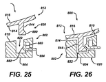
- peg 248A including recess 256A formed in cylindrical portion 252A of the peg 248A. It should be appreciated that the peg 248A may be suitable for the pegs of the second component 220 as well as for peg 226 of the first component 202.
- peg 248B Yet another form of a peg for use with the first and second components of the augmented glenoid assembly of the present invention is shown as peg 248B in FIG. 15B.
- the peg 248B is similar to the peg 248A of the FIG. 15A, except that the peg 248B includes a second angular groove 258B spaced from a first angular groove 256B.
- the grooves 256B and 258B are formed in cylindrical portion 252B of the peg 248B.
- peg 248C a peg for use in a component of the modular glenoid implant assembly of the present invention is shown as peg 248C.
- the peg 248C includes a plurality of pliable fins 256C formed on cylindrical portion 252C of the peg 248C.
- the pliable fins 256C are designed to bend or deflect on insertion to prevent the removal of the pegs 248C.
- peg 248D yet another form of a peg for use in the glenoid implant assembly of the present invention is shown as peg 248D.
- the peg 248D includes a series of rings 256D, that extend past the cylindrical portion 252D of the peg 248D.
- the rings 256D serve to assist in locking the pegs 248D into the glenoid cavity of the scapula 116.
- the articulating surface 216 of the second component 212 of the glenoid assembly 200 is shown in greater detail.
- the articulating surface 216 is opposed to the assembly surface 214 of the body 236 of the second component 212.
- the articulating surface 216 is as shown in FIG. 14, preferably replicates the glenoid fossa. Therefore, the articulating surface 216 is preferably concave.
- the articulating surface 214 may be defined by a radius R extending from origin 260.
- First component 202 may be positioned on the eroded posterior portion 262 of the scapula 116.
- the peg 226 of the first component 202 is secured into the scapula 216.
- the support surface 204 of the first component 202 and the second surface 206 of the first component 202 are positioned against the repaired resected surfaces of the glenoid fossa 115.
- the second component 212 may be positioned against the assembly surface 210 of the first component 202.
- the assembly surface 214 of the second component 212 may be positioned against the assembly surface 210 of the first component 202.
- the second component 212 may extend beyond the first component 202, and may as is shown in FIG. 15, extend to an anterior portion 264 of the scapula 116.
- the mounting portion 240 of the assembly surface 214 of the second component 212 may rest against a prepared surface of the glenoid fossa 115 of the scapula 116.
- the first component 202 may be secured to the second component 212 by means of the locking feature 220.
- the protrusion 244 is inserted into the void 222 of the first component 202.
- the second component 212 may further include mounting or securing feature 246 in the form of the central peg 248 and the mounting pegs 250.
- the pegs 248 and 250 are inserted into cavities 266 formed in the scapula for receiving the pegs 248 and 250.
- the cavities 266 may be generally cylindrical for receiving the pegs 248 and 250.
- first component 202 may be secured to the scapula 116 by means of fasteners.
- first component 202 may include two spaced apart openings 232 for receiving fasteners 234 in the form of, for example, cancellous screws.
- the first component 202 is positioned on the scapula 116 and the screws 234 are positioned through openings 232 and are tightened against the scapula 116 to secure the first component 202 to the scapula 116.
- the second component 212 is positioned on the first component 202.
- the implant assembly may be provided with a securement of the second component 212 that may include fasteners 268, which cooperate with openings 270 formed through the articulating surface 216 of the second component 212.
- the fasteners 268 may be in the form of a cancellous screws, which mate with the cancellous bone and the scapula 116 to assist in securing the second component 212 to the scapula 116.
- the locking feature 220 may be any feature to assist in securing the second component 212 to the first component 202.
- the second component 212 includes protrusion 244 while the first component 202 includes void 222, which is adapted for cooperation with the protrusion 244.
- the void 222 may be positioned in the second component 212 and the protrusion 244 may be positioned 2 in the first component 202.
- the protrusion 244 may have any shape and may as is shown in FIG. 13 be generally rectangular in cross section.
- the void 222 may likewise have a shape that preferably can conform to the protrusion 244. As shown in FIG. 13, the void 222 is in the form of a rectangular slot having a uniform cross-section to match that of the protrusion 244.
- FIG. 18A another embodiment of the present invention is shown as augmented glenoid implant assembly 200A.
- the glenoid implant assembly 200A is similar to the glenoid implant assembly 200 of FIGS. 12-18 except that the first component 202A of the glenoid implant assembly 200A is slightly different than the first component 202 of the glenoid implant assembly 200 of FIGS. 12-18.
- the first component 202A of the first embodiment 200A includes a pair of spaced apart pockets 235A positioned over openings 232A of the first component 202A.
- the openings 232A are sized for passage of the screws 234A through the openings 202A.
- FIG. 18B another embodiment of the present invention is shown as glenoid implant assembly 300.
- the glenoid implant assembly 300 is similar to the glenoid implant assembly 200 of FIGS. 12-19 except that the glenoid implant 300 is for use where, in addition to a posterior defect a second defect exists. For example, an anterior defect may also exist in the glenoid fossa 115 of the scapula 116.
- the glenoid implant assembly 300 includes a first component 302.
- the first component 302 is used to accommodate a posterior defect 303 as shown in phantom.
- the first component 302 is for attachment to the scapula 116.
- the first component 302 defines the support surface 304 for cooperation with the glenoid fossa 115 and a second surface 306 positioned adjacent a buttress 307 formed in the glenoid fossa 115.
- the first component 302 includes an assembly face 310.
- the augmented glenoid assembly further includes a second component 312.
- the second component is removably secured to the first component 302.
- the second component 312 includes an assembly surface 314.
- the assembly surface 314 of the second component 312 is in close approximation with the first component 302.
- the second component 312 further includes an articulating surface 316 opposed to the assembly surface 314.
- the glenoid assembly 300 further includes a third component 370.
- the third component 370 is utilized to accommodate an anterior defect 372.
- the third component 370 defines a support surface 374 for cooperation with the glenoid fossa 115.
- the third component 370 further includes an assembly face 376.
- the third component 370 is in the juxtaposition with the second component 312.
- the assembly surface 314 of the second component 312 is in close approximation to the assembly surface 376 of the third component 370.
- FIG. 18C-18F another embodiment of the present invention is shown as glenoid implant assembly 400.
- the glenoid implant assembly 400 of FIGS. 18C-18F is similar to the glenoid implant 200 of FIGS. 12-18 except the glenoid implant assembly 400 includes a second component 312 that is an assembly of two separate components.
- the glenoid implant assembly 400 includes a first component 402 and a second component 412.
- the first component 402 is similar to the first component 202 of the glenoid implant assembly 200 of FIGS. 12-18.
- the first component 402 includes a support surface 404 for cooperation with the scapula 116 as well as a second surface 406 for cooperation with a buttress formed on the scapula 116.
- the second component 406 further includes an assembly surface 410 for contact with the second component 412.
- the first component 402 may further include a securing feature 424 in the form of, for example, a peg.
- Glenoid implant assembly 400 also includes the second component 412.
- the second component 412 is somewhat similar in size and shape to the second component 212 of the augmented glenoid implant assembly 200 of FIGS. 12-18 except that the second component 412 is made from two components including a bearing component 480 and a backing component 482.
- the backing component 482 defines the assembly surface 414 for cooperation with assembly surface 410 of the first component 402.
- the bearing component 480 defines an articulating surface 416.
- the augmented glenoid implant assembly 400 is shown in an exploded view.
- the augmented glenoid implant assembly 400 as shown in FIG. 18D may include a locking feature 420 for locking the second component 412 to the first component 402.
- the backing component 482 of the second component 412 may include a protrusion 444 for cooperation with a void 422 formed in first component 402.
- the augmented glenoid implant assembly 400 of FIGS. 18C-18F may include securing features to assist in securing the glenoid assembly 400 to the scapula 116.
- the first component 402 may include a securing feature 424 in the form of a peg.
- the second component 412 may include a securing feature 448 in the form of, for example, a peg.
- the first component 402 and the second component 412 may be made of any suitable, durable material. Preferably the materials for which the first component 402 and the second component 412 are sterilizable.
- Component 402 may be made of, for example, a metal, a plastic, a ceramic, or a composite material.
- the second component 412 includes the backing component 482 and the bearing component 480.
- the backing component 482 may be made of any suitable, durable material.
- the backing component 482 may be made of a plastic or a metal, a composite, or a ceramic.
- the backing component 480 may be made of a metal. If made of a metal the backing component 482 may be made of, for example, cobalt chromium alloy, a titanium alloy, or a stainless alloy.
- the bearing component 480 may be made of any suitable, durable material.
- the bearing component 482 may be made of a ceramic, a composite, a plastic, or a metal. If made of a plastic, the bearing component 480 may be made of an ultra-high molecular weight polyethylene. If made of an ultra-high molecular weight polyethylene the bearing 480 may be made of a cross-linked, ultra-high molecular weight polyethylene such as that used in products sold by DePuy Orthopaedics Inc under the trade mark Marathon.
- the backing component 482 includes a second component assembly surface 484, which mates with a second component assembly surface 486 of the bearing component 480.
- the bearing component 480 is preferably securely fastened to the backing component 482.
- the bearing component 480 may be secured to the backing component 482 in any suitable fashion.
- the bearing component 480 may be, glued, welded, molded, or interferingly fitted to the backing component 482.
- the bearing component 480 may be secured to the backing component 482 by molding the bearing component 480 unto the backing component 482.
- the backing component 482 may include a porous surface on assembly surface 484.
- the porous surface may be, for example, as used in products sold by DePuy Orthopaedics, Inc under the trade mark Porocoat, and as generally disclosed in US-3855638.
- FIGS. 19 and 20 another embodiment of the present invention is shown as augmented glenoid assembly 500.
- the augmented glenoid assembly 500 of FIGS. 19 and 20 is generally similar to the glenoid assembly 200 of FIGS. 12-18.
- the glenoid implant assembly 500 includes a second component 512, which is lockably engaged to the first component 502.
- the first component 502 includes a support surface 504 for contact with the scapula 116.
- the first component 502 further includes an assembly surface 510.
- the second component 512 includes an articulating surface 516 and an opposed assembly surface 514.
- a locking feature 520 secures the second component 512 to the first component 502.
- the locking feature 520 includes a first component locking feature 522 in the form of a cavity, which designed to receive second component locking feature 544 in the form of a protrusion.
- the protrusion 544 as is shown in FIG. 19 and 20, includes a stem 584 extending from the assembly surface 514 of the second component 512.
- the protrusion 544 further includes a pliable tab 584 extending from the stem 582.
- the first component locking feature or cavity 522 includes an internal lip 586 for constraining the tab 584 when the second component 512 is engaged in the first component 502 (see FIG. 20).
- augmented glenoid implanted assembly 600 is generally similar to the glenoid assembly 200 of FIGS. 12-18, but includes a locking feature 620 that is somewhat different than the locking feature 220 of the glenoid implant assembly 200 of FIGS. 12-18.
- the glenoid implant assembly 600 includes a first component 602 having a support surface 604 and an opposed surface 610.
- a void or cavity 622 is formed from the assembly surface 610 of the first component 602.
- An urging member 686 extends into the cavity 622 of the first component 602.
- the urging member 686 is preferably resilient and includes an edge 688, which protrudes outwardly from the urging member 686.
- the glenoid implant assembly further includes the second component 612 having an articulating surface 616 and an opposed assembly surface 614.
- a protrusion 644 extends outwardly from assembly surface 614.
- the protrusion 644 includes a plurality of teeth 690 extending from the protrusion 644.
- the teeth 690 are adapted for engagement with the edge 688 of the urging member 686 when the second component 612 is in position with first component 602 (see FIG. 22).
- glenoid implant assembly 700 is similar to the glenoid implant assembly 200 of FIGS. 12-18 except that the glenoid implant assembly 700 includes a locking feature 720 that is somewhat different than the locking feature 220 of the glenoid implant assembly 200 of FIGS. 12-18.
- the gleniod implant assembly 700 includes a first component 702 having a support surface 704 and an opposed surface 710.
- a locking feature in the form of a void 722 extends inwardly from the assembly face 710.
- the first component 702 may further define an opening 780 for receiving a pin 782. While the pin 782 may be interferencely fitted to the opening 780, the pin 782 may include a plurality of teeth 784, which mates with groove 786 formed on the periphery on the opening 780 (see FIG. 23A).
- the second component may 712 further include a protrusion 744 extending outwardly from the assembly surface 714 of the second component 712.
- the protrusion 744 may include a notch 788 for cooperation with distal end 790 of the pin 782. The end 790 of the pin 782 matingly engages with the notch 788 of the protrusion 744 to secure the second component 712 onto the first component 702.
- augmented glenoid implant assembly 800 is similar to the augmented glenoid implant assembly 200 of FIGS. 12-18, but includes a locking mechanism 820, which is different than the locking mechanism 220 of the augmented glenoid implant assembly 200 of FIGS. 12-18.
- the glenoid implant assembly 800 includes a first component 802 having a support surface 804 and an opposed assembly surface 810. A cavity 822 extends from support surface 810.
- the cavity 822 has a pliable wall 880 including a beak 882, which extends inwardly into the cavity 822.
- the pliable wall 880 includes a wall extension 884 for releasing of the second component 812 from the first component 802.
- the augmented glenoid implant assembly 800 further includes second component 812 having an articulating surface 816 and an assembly surface 814.
- a protrusion 844 extends from the assembly surface 814 of the second component 812.
- the protrusion 844 includes a lip 890 for cooperation with the beak 882 of the wall 880.
- the lip 890 of the protrusion 844 deflects the beak 882 of the wall 880, permitting the protrusion 844 to fully locate in the cavity 822.
- the beak 882 of the wall 880 locks against the lip 890 of the protrusion 884 securing the second component 812 against the first component 802.
- augmented glenoid implant assembly 900 is similar to the glenoid implant assembly 200 of FIGS. 12-18 and includes a locking mechanism 920, that is different than the locking mechanism 220 of the augmented glenoid implant assembly 200 of FIGS. 12-18.
- the glenoid implant assembly 900 includes a first member 902 having a support surface 904 and an opposed assembly surface 910. An opening 922 is formed in the assembly 910. The opening 922 includes internal threads 980.
- the augmented glenoid implant assembly 900 further includes a second member 912 defining an articulating surface 916 and an opposed assembly surface 914.
- a protrusion 944 extends from the assembly 914 and is designed to fit in the opening 922.
- the protrusion 944 includes external threads 982, which mate with internal threads 980 of the opening 922 of the first member 902.
- FIG. 28 yet another embodiment of the present invention as an augmented glenoid implant assembly 1000.
- the augmented glenoid implant assembly 1000 is similar to the augmented glenoid implant assembly 200 of FIGS. 12-18 except that the glenoid implant assembly 1000 includes a locking mechanism 1020, that is different than the locking mechanism 220 of the glenoid implant assembly 200 of FIGS. 12-18.
- the glenoid implant assembly 1000 includes a first member 1002 having a support surface 1004 and an opposed assembly surface 1010.
- a void 1022 extends inwardly from the assembly surface 1010.
- the glenoid implant assembly 1000 further includes a second member 1012 having an articulating member 1016 and an opposed 1014.
- a protrusion 1044 extends outwardly from the assembly surface 1014.
- the protrusion 1022 includes an angular rib 1080, which mates with an angular groove 1082 formed on the first member 1002 in the opening 1022.
- the resilient rib 1080 protrusion 1044 fits in the angular groove 1080 of the opening 1022 to secure the second member 1012 to the first member 1002.
- augmented glenoid implant assembly 1100 is similar to the augmented glenoid implant assembly 200 of FIGS. 12-18, but includes a locking feature 110 which is somewhat different the locking feature 220 of the augmented gleniod implant assembly 200 of FIGS. 12-18.
- the augmented glenoid implant assembly 1100 includes a first component 1102 defining a support surface 1104 and an opposed assembly 1110.
- the first component 1102 further includes a second surface 1106 positioned against buttress 1107 formed in the glenoid fossa 115 of the scapula 116.
- the augmented glenoid implant assembly 1100 further includes a second component 1112 defining an articulating surface 1116 and an opposed assembly surface 1114.
- the assembly surface 1114 includes a mounting portion 1114 for engagement with the glenoid fossa 115 as well as an assembly portion 1142 for engagement with the assembly surface 1110 of the first component 1102.
- the locking feature 1120 includes a protrusion 1144 extending outwardly from assembly portion 1142 of the assembly surface 1114 of the second component 1102.
- the protrusion 1144 is generally rectangular cross-section and includes a length LP, which is substantially greater than its width WP.
- the protrusion 1144 is designed to be matingly fitted with slot 1122 formed in the first component 1102.
- the slot 1122 is generally rectangular having a width WS, which is substantially smaller than its length LS.
- Slot 1122 may define arcuate portions 1123 and the protrusion 1144 may likewise have arcuate portions 1145 (see FIG. 32).
- protrusion of 1144 of the second component 1112 is inserted into the slot 1122 of the first component 1102 to form the locking feature 1120 to secure the second component 1112 to the first component 1102.
- the first component 1102 may include a protrusion in the form of a fin 1124 extending from support surface 1104 to secure the first component 1102 to the glenoid fossa 115 of the scapula 116.
- the fin 1124 may have any suitable shape and may for example have a width WF which is much smaller than the leg LF.
- the fin 1124 has a generally rectangular cross section.
- the first component 1102 may include additional features to secure the first component 1102 to the glenoid fossa 115 of the scapula 116.
- the first component 1102 may include a pair of spaced apart openings 1132 through which screws 1134 in the form of for example cancellous screws are used to secure the first component 1102 to the glenoid fossa 115 of the scapula 116.
- glenoid implant assembly 1100 is shown being assembled onto repaired surface 123 of the scapula 116.
- the first component 1102 is positioned over and inserted into posterior prepared surface 122.
- a groove 122 may be prepared in the posterior surface 127.
- a pair of spaced apart openings 127 may be prepared in the posterior prepared surface 122.
- the first component 1102 is positioned over and secured to the posterior prepared surface 122.
- the fin 1124 is positioned in groove 122 and the screws 1134 are positioned through holes 1102 in the first component 1102 and engaged in holes 127 formed in the posterior prepared surface 122.
- the second component 1112 is positioned onto the first component 1102 posterioraly and onto anterior prepared surface 119 anteriorly.
- the protrusion 1144 of the second component 1112 is positioned in groove of 1122 formed in the first component 1102.
- the articulating surface 1116 of the second component 1112 is designed for cooperation with humeral head 1139 of femoral prosthesis of 1133.
- the humeral head 1139 extends outwardly from humeral stem 1135 of humeral prosthesis 1133.
- the humeral stem 1135 is positioned in humeral canal 141 of the humerus 143.
- the method 1200 includes a first step 1202 of forming a buttress in a portion of a glenoid surface of a scapula.
- the method 1200 further includes a second step 1204 of providing a base glenoid component having a glenoid contacting surface configured to contact the portion of the surface of the glenoid scapula.
- the base glenoid component also has a connecting surface based from the glenoid contact surface and a buttress surface for cooperation with the buttress shaped recess.
- the method 1200 further includes a third step 1206 of securing the base glenoid component to the glenoid surface of the scapula such as the glenoid compacting surface is positioned in contact with the glenoid surface of the scapula and the buttress surface is positioned against the buttress shaped recess.
- the method 1200 further includes a fourth step 1208 of providing a bearing component removeably secured to the base glenoid component the bearing component includes an assembly face and an imposed articulating surface configured to be contacted by the head portion of the humerus.
- the method 1200 further includes a fifth step 1210 of securing the bearing component to the base glenoid component such that the articulating surfaces positioned to be contacted by the head portion of the humerus and the assembly surface of the bearing component is positioned against the connecting surface of the base glenoid component.
Landscapes
- Health & Medical Sciences (AREA)
- Orthopedic Medicine & Surgery (AREA)
- Cardiology (AREA)
- Oral & Maxillofacial Surgery (AREA)
- Transplantation (AREA)
- Engineering & Computer Science (AREA)
- Biomedical Technology (AREA)
- Heart & Thoracic Surgery (AREA)
- Vascular Medicine (AREA)
- Life Sciences & Earth Sciences (AREA)
- Animal Behavior & Ethology (AREA)
- General Health & Medical Sciences (AREA)
- Public Health (AREA)
- Veterinary Medicine (AREA)
- Prostheses (AREA)
- Organic Low-Molecular-Weight Compounds And Preparation Thereof (AREA)
- Percussion Or Vibration Massage (AREA)
- Machine Translation (AREA)
- Cookers (AREA)
Abstract
Description
- The present invention relates generally to the field of orthopaedics, and more particularly, to an implant for use in arthroplasty.
- During the lifetime of a patient, it may be necessary to perform a total shoulder replacement procedure on the patient as a result of, for example, disease or trauma. In a total shoulder replacement procedure, a humeral component having a head portion is utilized to replace the natural head portion of the arm bone or humerus. The humeral component typically has an elongated intramedullary stem which is utilized to secure the humeral component to the patient's humerus. In such a total shoulder replacement procedure, the natural glenoid surface of the scapula is resurfaced or otherwise replaced with a glenoid component that provides a bearing surface for the head portion of the humeral component.
- As alluded to above, the need for a shoulder replacement procedure may be created by the presence of any one of a number of conditions. One such condition is the deterioration of the patient's scapula in the area proximate to the glenoid surface as a result of, for example, glenohumeral arthritis. In such a condition, the erosion of the patient's scapula is generally observed posteriorly on the glenoid surface. Such erosion of the scapula renders treatment difficult, if not impossible, with a conventional glenoid prosthesis.
- In order to treat a condition in which a portion of the scapula has been eroded, a number of glenoid prostheses have heretofore been designed. Such glenoid prostheses, known generally as augmented glenoid prostheses, have a posterior edge that is thicker than the corresponding anterior edge.
- In FIG. 1, a heretofore-designed augmented
glenoid component 100 is shown. Theglenoid component 100 has ametallic backing component 102 andplastic insert 104. The thickness of themetallic backing component 102 gradually increases from ananterior edge 106 to aposterior edge 108 thereof thereby creating a relatively smooth, arcuate-shapedmedial surface 110 from which a number of posts orpegs 112 extend. - The design of the augmented
glenoid component 100, however, has a number of associated drawbacks. For example, the relatively smooth, arcuate-shapedmedial surface 110 may over time lead to loosening of the augmentedglenoid component 100, thereby potentially necessitating additional surgical procedures to replace or reseat thecomponent 100. Further, due to the configuration of themedial surface 110, a relatively high shear load is created along the implant-to-bone interface when thecomponent 100 is implanted. The presence of a high shear load along the implant-to-bone interface tends to also cause loosening of thecomponent 100 over a period of time. Post-operative loosening is the largest cause of failures of implanted glenoid components. - In FIG. 2 another heretofore-designed augmented
glenoid component 100A is shown. Theglenoid component 100A has a single componentplastic body 102A. The thickness of theplastic body 102A gradually increases from ananterior edge 106A to aposterior edge 108A thereof thereby creating a relatively smooth, arcuate-shapedmedial surface 110A from which a number of posts orpegs 112A extend. The design of this augmentedglenoid component 100A, however, suffers from at least the same drawbacks as theglenoid component 100. - In FIG. 3 another heretofore-designed augmented
glenoid component 100B is shown. Theglenoid component 100B also has a single componentplastic body 102B. The thickness of theplastic body 102B gradually increases from ananterior edge 106B to aposterior edge 108B thereof thereby creating a relatively smoothmedial surface 110B from which akeel 114B extends. The design of this augmentedglenoid component 100B, however, suffers from at least the same drawbacks as theglenoid components - What is needed therefore is an augmented glenoid component that overcomes one or more of the above-mentioned drawbacks. What is further needed is an augmented glenoid component that is less susceptible to postoperative loosening relative to heretofore designed glenoid components.
- Attempts have been made in the prior art to provide for a glenoid implant that accommodates posterior erosion. In fact, a device has been designed for augmented glenoid component to accommodate posterior erosion. This attempt at finding a glenoid component to accommodate erosion has provided for generally compressive load and minimize the shear load earlier prior art devices. This device is described in US-6699289 to Iannotti et al.
- Referring now to FIG. 18A, another embodiment of the present invention is shown as augmented
glenoid implant assembly 200A. Theglenoid implant assembly 200A is similar to theglenoid implant assembly 200 of FIGS. 12-18 except that thefirst component 202A of theglenoid implant assembly 200A is slightly different than thefirst component 202 of theglenoid implant assembly 200 of FIGS. 12-18. Thefirst component 202A of thefirst embodiment 200A includes a pair of spaced apartpockets 235A positioned overopenings 232A of thefirst component 202A. Theopenings 232A are sized for passage of thescrews 234A through theopenings 202A. Thepockets 235A are used to provide for thelocation heads 237A of thescrews 234A. - Referring now to FIG. 4, a
scapula 116 is shown withposterior wear 118.Glenoid component 120 as shown in phantom includes anarticulating surface 122, which is symmetrically positioned with respect to thescapula 116. Thus, shown in FIG. 4, theglenoid component 120 is required to be thicker or higher at the portion of thescapula 116 with theposterior defect 118. As shown in FIG. 4, theload factor 124 for theglenoid component 120 is in a different orientation than theload factor 126 normal to theworn scapula 116. Thus, theglenoid component 120 positioned on thescapula 116 includes aforce vector 128 that is in shear and that my cause loosening of the glenoid component. - Referring now to FIG. 5, the
scapula 116 may be prepared by a buttress orstep 130 such that there are twosupport surfaces scapula 116. Preparation of the glenoid cavity is shown in US-6699289. Referring now to FIG. 6, supportload vectors 136 are shown parallelload force vectors 138 of theglenoid component 140. - The device of Iannotti provides for and improvement of the load distribution placed upon the glenoid component. This device provides generally for a one piece glenoid component, which is optimum for one particular posterior erosion pattern. A need remains for a posterior augmented glenoid component that may accommodate a wide variety of posterior erosion conditions that may minimize the quantity and types of components necessary to provide for a wide variety of patient needs.
- The present invention provides a n augmented glenoid implant assembly comprising:
- a first component for attachment to the glenoid fossa, said first component defining an support surface for cooperation with the glenoid fossa and an assembly surface, said first component extends only over a portion of the glenoid fossa; and
- a second component removably secured to said first component, said second component including an assembly face thereof, the assembly face of said second component in close approximation to the assembly surface of said first component, said second component further comprising an articulating surface opposed to the assembly surface.
- In another aspect, the invention provides an augmented glenoid implant assembly for cooperation with the glenoid fossa of a scapula, said implant assembly comprising:
- a first component for attachment to the scapula, said first component defining an support surface for cooperation with the glenoid fossa, a second surface positioned adjacent a buttress formed in the glenoid fossa and an assembly surface; and
- a second component removably secured to said first component, said second component including an assembly face thereof, the assembly surface of said second component in close approximation to the assembly surface of said first component, said second component further comprising an articulating surface opposed to the assembly surface.
- The apparatus provided by the invention can be used in a method of performing shoulder arthroplasty comprising the steps of:
- forming a buttress-shaped recess in a portion of glenoid surface of a scapula;
- providing a base glenoid component having a glenoid contacting surface configured to contact the portion of the glenoid surface of the scapula, a connecting surface spaced from the glenoid contacting surface, and a buttress surface for cooperation with the buttress-shaped recess;
- securing said base glenoid component to the glenoid surface of the scapula such that the glenoid contacting surface is positioned in contact with the glenoid surface of the scapula, and the buttress surface is positioned against the buttress-shaped recess;
- providing a bearing component removably secured to said base glenoid component, said bearing component including an assembly surface thereof and an opposed articulating surface configured to be contacted by the head portion of the humerus; and
- securing said bearing component to said base glenoid component such that the articulating surface is positioned to be contacted by the head portion of the humerus and assembly surface of said bearing component is positioned against the connecting surface of said base glenoid component.
- According to the present invention, a modular posterior augmented glenoid system is provided. The system includes a buttress, which is separate from an articulating component. A buttress may be made of any suitable, durable material and may, for example, made of a metal. The articulating component may be unitary or have two parts and may include a metal backing and a polyethylene articulating component. The buttress may be secured for fixation to the bone. For example, the buttress may include openings to cooperate with screws for fixing the buttress to the bone. The metal backed or polyethylene bearing component may be have a bone cement fixation element as well as an interlocking element fixed to the buttress. The modular glenoid system of the present invention has the potential to adapt for various types of defects and size combinations. The buttress can be configured to permit use of currently available glenoid articulating components to treat posterior erosion.
- The modular posterior augmented glenoid system of the present invention may utilize a set of specific reamers to mill a step into the glenoid fossa matched to specific categories of posterior defects. Each depth created by the milling operation may have a corresponding buttress that is secured to the bone below the coracoid and the auxiliary border of the scapular blade.
- The buttress may include a keel to help align and support the implant. The articulating component may have two or more distinct fixation mechanisms. The buttress can also have a feature that permits the use of currently commercially available primary glenoids, for example, the global glenoid offered by DePuy Orthopaedics, Warsaw, IN in the restoration of normal shoulder function. The feature of the glenoid would have a mechanism to lock the component to the metal buttress. The fixation mechanism for rigid attachment to the buttress can be configured for cemented or cementless fixation to the remaining support bone. If the articulating component is metal backed, the rigid fixation of the metal backing and the metal buttress can be accomplished with screws, snap lock, or other fixation means. The bone fixation can be made with a cemented peg, with porocoat, or by some other means. In the poly-articulating components the rigid fixation can be from snap lock or some other interference means, and the bone fixation can be an anchor peg, cement peg, keel, or some other means.
- According to one embodiment of the present invention, there is provided an augmented glenoid implant assembly for cooperation with the glenoid fossa of a scapula. The implant assembly includes a first component for attachment to the scapula. The first component defines a support surface for cooperation with the glenoid fossa, a second surface positioned adjacent a buttress formed in the glenoid fossa and an assembly surface. The implant assembly also includes a second component removably secured to the first component. The second component includes an assembly face of the second component. The assembly surface of the second component is in close approximation to the assembly surface of the first component. The second component further includes an articulating surface opposed to the assembly surface.
- According to another embodiment of the present invention there is provided an augmented glenoid implant assembly. The augmented glenoid implant assembly includes a first component for attachment to the glenoid fossa. The first component defines a support surface for cooperation with the glenoid fossa and an assembly surface. The first component extends only over a portion of the glenoid fossa. The augmented glenoid implant assembly also includes a second component removably secured to the first component. The second component includes an assembly face of the second component.
- The assembly face of the second component is in close approximation to the assembly surface of the first component. The second component further includes an articulating surface opposed to the assembly surface.
- According to a further embodiment of the present invention, there is provided a method of performing shoulder arthroplasty. The method includes the steps of forming a buttress-shaped recess in a portion of glenoid surface of a scapula and providing a base glenoid component. The base glenoid component has a glenoid contacting surface configured to contact the portion of the glenoid surface of the scapula and a connecting surface spaced from the glenoid contacting surface. The base glenoid component also includes a buttress surface for cooperation with the buttress-shaped recess. The method also includes the step of securing the base glenoid component to the glenoid surface of the scapula such that the glenoid contacting surface is positioned in contact with the glenoid surface of the scapula and the buttress surface is positioned against the buttress-shaped recess. The method further includes the step of providing a bearing component removably secured to the base glenoid component. The bearing component includes an assembly surface and an opposed articulating surface configured to be contacted by the head portion of the humerus. The method further includes the step of securing the bearing component to the base glenoid component such that the articulating surface is positioned to be contacted by the head portion of the humerus and assembly surface of the bearing component is positioned against the connecting surface of the base glenoid component.
- The technical advantages of the present invention include the ability of the present invention to provide for prostheses support for a glenoid with a posterior defect. For example, according to one aspect of the present invention, an augmented glenoid assembly is provided. The implant assembly cooperates with the glenoid fossa of a scapula. The implant assembly includes a first component for attachment to the scapula. The first component defines the support surface for cooperation with a glenoid fossa and a second surface in positioning adjacent a buttress formed in the fossa and in assembly surface. The implant assembly further includes a second component removably secured to the second component. The first component provides support for the glenoid with the posterior defect.
- Thus the present invention provides for a prosthesis having support for a glenoid with a posterior defect.
- The technical advantages to the present invention further include the ability of the prosthesis of the present invention to re-establish normal glenoid version or orientation. For example, according to one aspect of the present invention, an augmented glenoid implant assembly is provided for cooperation with a glenoid fossa of the scapula. The implant assembly includes a first component for attachment to the scapula and a second component removably secured to the first component. The second component includes an assembly face thereof. The second component further includes an articulating surface opposed to the assembly surface. The assembly and the articulating surface are positioned such that normal glenoid version is re-established. Thus, the present invention provides for the re-establishment of a normal glenoid version.
- The technical advantages of the present invention further include the ability of the prosthesis of the present invention to reduce loosening of the implant by matching the strain pattern of the glenoid to the implant or by providing an implant which experiences no shear force, and its normal force to the natural glenoid. For example and according to one aspect of the present invention, augmented glenoid assembly provided including a first component for attachment to the glenoid fossa. The first component defines a support surface and extends over a portion of the glenoid fossa. The first component has an assembly surface in alignment with the strain pattern to provide for no shear forces as does the support surface of the first component. Thus, the present invention provides for the reduction of loosening of the implant by providing a normal strain pattern and by eliminating the shear force.
- Technical advantages of the present invention further include the ability of the glenoid assembly of the present invention to provide for modularity or for the combination of components to provide for a large variety of combinations with a smaller number of components. Such modularity provides for lower costs, reduced inventory, and greater offerings of combinations and better fit for patients. For example, according to another aspect of the present invention, an augmented glenoid assembly provides for cooperation with the glenoid fossa of the scapula. The implant assembly includes a first component for attachment to the scapula and a second component removably secured to the first component. Thus, the present invention provides for modularity or the combination of components to provide for greater flexibility and more offerings for the patient.
- The technical advantages of the present invention also include the ability of the glenoid assembly of the present invention to include a glenoid bearing that may be used without a posterior defect. The present invention provides for use with a normal standard glenoid component. For example, according to another aspect of the present invention, an augmented glenoid assembly is provided for cooperation with the glenoid fossa of the scapula. The implant assembly includes a first component for attachment to the scapula and a second component removably secured to the first component. The first component extends over a portion of the glenoid fossa. The first component thus, may be used to accommodate the posterior defect. The augmented glenoid assembly also includes a second component that is positioned over substantially all the glenoid fossa. This second component may be identical to the glenoid component used for a natural glenoid without an extensive wear or posterior defect. Thus, the present invention provides for a glenoid bearing that may be used without a posterior defect.
- Embodiments of the invention will now be described by way of example with reference to the accompanying drawings, in which:
- FIG. 1 is a side sectional view of a prior art augmented glenoid component;
- FIG. 2 is a side sectional view of another prior art augmented glenoid component;
- FIG. 3 is a side sectional view of another prior art augmented glenoid component;
- FIG. 4 is a side view of a prior art posterior augmented glenoid component in position on a glenoid, showing a undesirable shearing force vector;
- FIG. 5 is a side view of a glenoid cavity prepared for a stepped posterior augmented glenoid component;
- FIG. 6 is a side sectional view of the glenoid cavity prepared for a stepped posterior augmented glenoid component showing the preferred normal force vectors;
- FIG. 7 is a perspective view showing a unitary prior art augmented glenoid component;
- FIG. 8 is another perspective view of the augmented glenoid component of FIG. 7;
- FIG. 9 is an end view of the augmented glenoid component of FIG. 7;
- FIG. 10 is an bottom view of the augmented glenoid component of FIG. 7;
- FIG. 11 is a side view of the augmented glenoid component of FIG. 7;
- FIG. 12 is a perspective view of another embodiment of a modular augmented glenoid assembly of the present invention;
- FIG. 13 is an exploded perspective view of the glenoid assembly of FIG. 12;
- FIG. 14 is a perspective view showing a modular augmented glenoid component of the glenoid assembly of FIG. 12 in accordance with another embodiment of the present invention;
- FIG. 15 is a bottom, right-angled perspective view of an embodiment of a glenoid bearing for cooperation with the modular augmented glenoid component of FIG. 14;
- FIG. 15A is a partial plane view of a glenoid bearing with a grooved anchor peg;
- FIG. 15B is a partial plane view of a glenoid bearing with a double grooved peg;
- FIG. 15C is a partial plane view of a glenoid bearing with a flexible finned;
- FIG. 15D is a partial plane view of a glenoid bearing with a finned peg;
- FIG. 16 is a top, left-angled perspective view of the glenoid bearing of FIG. 15;
- FIG. 17 is an plan view partially in cross section showing the modular augmented glenoid assembly of FIG. 12 in position on a glenoid;
- FIG. 18 is an exploded perspective view of the glenoid assembly of FIG. 12 including fastener;
- FIG. 18A is a perspective view showing a modular augmented glenoid component in accordance with another embodiment of the present invention showing alternate provisions for fasteners to secure the component
- FIG. 18B is an plan view partially in cross section showing a modular augmented glenoid component in accordance with another embodiment of the present invention having a two piece reinforced second component in position on a glenoid;
- FIG. 18B is a perspective view showing a modular augmented glenoid component in accordance with an embodiment of the present invention;
- FIG. 18C is a perspective view of the modular augmented glenoid assembly of FIG. 18B;
- FIG. 18D is an exploded perspective view of the modular augmented glenoid assembly of FIG. 18B;
- FIG. 18E is a perspective view of the second component of the modular augmented glenoid assembly of FIG. 18B;
- FIG. 18F is another perspective view of the second component of the modular augmented glenoid assembly of FIG. 18B;
- FIG. 19 is an exploded partial plan view of yet another embodiment of the present invention in the form of a modular augmented glenoid assembly including a locking feature in the form of a tab and a cavity;
- FIG. 20 is a partial plan view of the modular augmented glenoid assembly of FIG. 19;
- FIG. 21 is an exploded partial plan view of another embodiment of the present invention in the form of a modular augmented glenoid assembly including a locking feature in the form of a protrusion and a void with an urging member;
- FIG. 21A is a partial view of the protrusion of the second component of the glenoid assembly of FIG. 21 showing the teeth of the protrusion;
- FIG. 22 is a partial plan view of the modular augmented glenoid assembly of FIG. 21;
- FIG. 23 is an exploded partial plan view of a further embodiment of the present invention in the form of a modular augmented glenoid assembly including a locking feature in the form of a pawl and a notch;
- FIG. 24 is a partial plan view of the modular augmented glenoid assembly of FIG. 23;
- FIG. 25 is an exploded partial plan view of a further embodiment of the present invention in the form of a modular augmented glenoid assembly including a locking feature in the form of a cavity and a protrusion;
- FIG. 26 is a partial plan view of the modular augmented glenoid assembly of FIG. 25;
- FIG. 27 is an exploded partial plan view of a yet another embodiment of the present invention in the form of a modular augmented glenoid assembly including a locking feature in the form of threads;
- FIG. 28 is an exploded partial plan view of a further embodiment of the present invention in the form of a modular augmented glenoid assembly including a locking feature in the form of a rib;
- FIG. 29 is an plan view partially in cross section of another embodiment of the present invention in the form of a modular augmented glenoid assembly in position on a glenoid with the locking feature in the form of fin;
- FIG. 30 is a top view of the modular augment glenoid component of the modular augmented glenoid assembly of FIG. 29;
- FIG. 31 is a cross section view of the modular augment glenoid component of FIG. 30 along the lines 31-31 in the direction of the arrows;
- FIG. 32 is a perspective view of the bearing component of the glenoid assembly of FIG. 29;
- FIG. 32A is a perspective view of an alternate bearing component for use with the modular glenoid component of FIG. 30;
- FIG. 33 is a plan view of the modular augment glenoid component of FIG. 30;
- FIG. 34 is a end view of the modular augment glenoid component of FIG. 30;
- FIG. 35 is an exploded perspective view of glenoid vault of a scapula, a humerus, and the modular augmented glenoid assembly of FIG. 29; and
- FIG. 36 is a flow chart for a method of performing shoulder arthroplasty in accordance to yet another embodiment of the present invention.
- Referring to the drawings, FIG.7-11 show a stepped
glenoid component 140 which includes an articulatingsurface 142 as well as opposed mounting surfaces 144. Theglenoid component 140 may include a posterior augment 146 as well as anchoringpegs 148 and acentral peg 150. - According to the present invention and referring now to FIGS. 12 and 13, an augmented
gleniod implant assembly 200 to shown for use in theglenoid fossa 115 of thescapula 116. Theimplant assembly 200 includes afirst component 202 for attachment to thescapula 116. Thefirst component 202 defines asupport surface 204 for cooperation with theglenoid fossa 115. Thefirst component 202 also includes asecond surface 206 adapted to be adjacent, a buttress 208 formed in theglenoid fossa 115 of thescapula 116. Thefirst component 202 also includes anassembly face 210 opposed to thesupport surface 204. Theimplant assembly 200 further includes asecond component 212. Thesecond component 212 is removably secured to thefirst component 202. Thesecond component 212 includes anassembly phase 214 of thesecond component 212. Theassembly 214 of thesecond component 212 is in close approximation to theassembly surface 210 of thefirst component 202. Thesecond component 212 further includes an articulatingsurface 216 opposed to theassembly surface 214. - The augmented
glenoid implant assembly 200 including thefirst component 202 and thesecond component 212 may be made of any suitable, durable material. For example, thefirst component 202 and or thesecond component 212 can be made of a metal. For example, if made of a metal thefirst component 202 and thesecond component 212 may be made of a cobalt chromium alloy, a titanium alloy, or a stainless steal alloy. Thecomponents first component 202 and thesecond component 212 may be made of, for example, an ultra high molecular weight polyethylene. For example, thesecond component 212 and thefirst component 202 can be made of cross-linked high ultra high molecular weight polyethylene, for example as in the product sold by DePuy Orthopaedics, Inc. under the trade mark Marathon and as disclosed in US-6228900. - Referring now to FIG. 14, the
first component 202 is shown in greater detail. Thefirst component 202 may have any suitable shape capable of providing for aglenoid implant assembly 200 to the patient. Thefirst component 202 may have a shape conforming to the posterior defect of the glenoid. Thefirst component 202 may have a shape corresponding to a cavity prepared with a buttress or step as disclosed in US-6699289. - As shown in FIG. 14, the
second component 202 may includeassembly surface 210 for assembly with thesecond component 212 as well as thesupport surface 204, which is spaced apart from theassembly surface 210. Thesupport surface 204 and theassembly surface 210 may be spaced apart and generally parallel with each other. - The
support surface 204 may have any suitable shape and may for simplicity be planar. Alternatively, thesupport surface 204 may be arcuate. It should be appreciated that thesupport surface 204 can conform to a surface easily prepared in the scapula by commercially available orthopaedic instrumentation. - The
assembly surface 210 may be any suitable surface and may be planar or accurate. Theassembly surface 210 should be designed to be combatable with the mating surface of thesecond component 212. Thesecond surface 206 of thefirst component 202 is adapted for close proximity to the buttress prepared in the glenoid cavity. For example and for simplicity, thesecond surface 206 may be planar to conform to a buttress machined into aglenoid fossa 115 of thescapula 116. - As shown in FIG. 14, the
first component 202 includes aperiphery 218, which may have any suitable shape. Theperiphery 218 may have, for example, a shape similar to the shape of the natural glenoid fossa. - As shown in FIG. 14, the
glenoid implant assembly 200 may include a locking or securingfeature 220 to secure thesecond component 212 to thefirst component 202. Thelocking feature 220 may include a firstcomponent locking feature 222. The firstcomponent locking feature 222 may be in the form of, for example and as is shown in FIG. 14, a cavity or void 222. The void 222 may have any suitable shape and may, for example and as is shown in FIG. 14, have a rectangular cross section. It should be appreciated that the void 222 may have any suitable shape, such as a cylindrical, triangular, or any shape. - The augmented
glenoid implant assembly 200 may include a securingfeature 224 for assisting and securing thefirst component 202 to thescapula 116. The securingfeature 220 my include afirst securing feature 226 that is operably assisted with thefirst component 202. Thefirst securing feature 226 may, as shown in FIG. 14 extend downwardly fromsupport surface 204 of thefirst component 202. Thefirst securing feature 226 may have any suitable shape for providing securement to thefirst component 202 to thescapula 116. Thefirst securing feature 226 may as shown in FIG. 14 have a generally cylindrical shape. - The
first securing feature 226 as shown in FIG. 14, may be in the form of apeg 226 including acylindrical portion 228 extending from thesupport face 204 of thefirst component 202 and aconical portion 230 extending from thecylindrical portion 228. - The securing
feature 224, as is shown in FIG. 14, may also include a second securing feature in the form of spaced apartopenings 232 for cooperation withfasteners 234. Thefasteners 234 may be in the form of cortical screws for engagement with cortical bone of scapula. - Referring now to FIGS. 15 and 16, the
second component 212 of the augmentedglenoid implant assembly 200 is shown in greater detail. Thesecond component 212 may be made of any suitable, durable material. Preferably the material for thesecond component 212 is sterilizible by a commercially available sterilization technique. Such sterilization techniques include autoclaving, gamma irradiation as well as other processes. - The
second component 212 may be made of a metal, a biological material, ceramic, alloy, zirconium, a carbon fiber material, a composite, or a plastic. If made of a metal, thesecond component 212 may be made of, for example, cobalt chromium alloy, a stainless steel alloy, or a titanium alloy. If made of a plastic, thesecond component 212 may be made of, for example, polyethylene. The second component can be made of an ultra high molecular weight polyethylene. If made of an ultra high molecular weight polyethylene the second component may be made of a cross-linked material, for example, polyethylene as in products sold by DePuy Orthopaedics, Inc under the trade mark Marathon. - The
second component 212 may have any suitable size and may be adapted to conform to the shape of the natural glenoid. Thesecond component 212, as is shown in FIG. 13, may include abody 236. Thebody 236 defines an articulatingsurface 216 and anopposed assembly surface 214. Thebody 236 further includes aperiphery 238 between the articulatingsurface 216 and theassembly surface 214. Thesecond component 212 of theimplant assembly 200 may include a mountingportion 240 for cooperation with the impaired glenoid and anassembly portion 242 for cooperation with theassembly surface 210 of thefirst component 202. - The
second component 212 may include a secondcomponent locking feature 244 of thesecond component 212 in the form of, for example and as is shown in FIG. 13, a protrusion.Protrusion 244 is adapted with cooperation with thevoid 222 of thefirst component 202. Thelocking feature 244 and the void 222form securing feature 224. - The
second component 212 may also include a mountingfeature 246 for assisting and securing thesecond component 212 to the glenoid 115 of thescapula 116. For example and as is shown in FIG. 15, the mountingfeature 246 may include acenter peg 248 extending downwardly fromassembly surface 214 of thesecond component 212. In addition to thecenter peg 246,additional pegs 250 may likewise extend downwardly from theassembly surface 214 of thesecond component 212. - The
pegs cylindrical portion 252 extending from the mountingportion 240 from theassembly face 214 and including a conical portion 254 extending from thecylindrical portion 252. It should be appreciated that thepegs pegs - Referring now to FIG. 15A, an alternative embodiment of the
pegs peg 248A including recess 256A formed incylindrical portion 252A of thepeg 248A. It should be appreciated that thepeg 248A may be suitable for the pegs of thesecond component 220 as well as forpeg 226 of thefirst component 202. - Yet another form of a peg for use with the first and second components of the augmented glenoid assembly of the present invention is shown as
peg 248B in FIG. 15B. Thepeg 248B is similar to thepeg 248A of the FIG. 15A, except that thepeg 248B includes a secondangular groove 258B spaced from a firstangular groove 256B. Thegrooves cylindrical portion 252B of thepeg 248B. - Referring now to FIG. 15C, yet another embodiment a peg for use in a component of the modular glenoid implant assembly of the present invention is shown as
peg 248C. Thepeg 248C includes a plurality ofpliable fins 256C formed oncylindrical portion 252C of thepeg 248C. Thepliable fins 256C are designed to bend or deflect on insertion to prevent the removal of thepegs 248C. - Referring now to FIG. 15D, yet another form of a peg for use in the glenoid implant assembly of the present invention is shown as
peg 248D. Thepeg 248D includes a series ofrings 256D, that extend past the cylindrical portion 252D of thepeg 248D. Therings 256D serve to assist in locking thepegs 248D into the glenoid cavity of thescapula 116. - Referring now to FIG. 16, the articulating
surface 216 of thesecond component 212 of theglenoid assembly 200 is shown in greater detail. The articulatingsurface 216 is opposed to theassembly surface 214 of thebody 236 of thesecond component 212. The articulatingsurface 216 is as shown in FIG. 14, preferably replicates the glenoid fossa. Therefore, the articulatingsurface 216 is preferably concave. For example, the articulatingsurface 214 may be defined by a radius R extending fromorigin 260. - Referring now to FIG. 17, the augmented
glenoid assembly 200 is shown in position on thescapula 116.First component 202, as is shown in FIG. 17, may be positioned on the erodedposterior portion 262 of thescapula 116. Thepeg 226 of thefirst component 202 is secured into thescapula 216. Thesupport surface 204 of thefirst component 202 and thesecond surface 206 of thefirst component 202 are positioned against the repaired resected surfaces of theglenoid fossa 115. Thesecond component 212 may be positioned against theassembly surface 210 of thefirst component 202. Theassembly surface 214 of thesecond component 212 may be positioned against theassembly surface 210 of thefirst component 202. - As shown in FIG. 17, the
second component 212 may extend beyond thefirst component 202, and may as is shown in FIG. 15, extend to ananterior portion 264 of thescapula 116. The mountingportion 240 of theassembly surface 214 of thesecond component 212 may rest against a prepared surface of theglenoid fossa 115 of thescapula 116. Thefirst component 202 may be secured to thesecond component 212 by means of thelocking feature 220. Theprotrusion 244 is inserted into thevoid 222 of thefirst component 202. Thesecond component 212 may further include mounting or securingfeature 246 in the form of thecentral peg 248 and the mounting pegs 250. Thepegs cavities 266 formed in the scapula for receiving thepegs cavities 266 may be generally cylindrical for receiving thepegs - Referring now to FIG. 18, the
first component 202 may be secured to thescapula 116 by means of fasteners. For example and is shown in FIG. 18,first component 202 may include two spaced apartopenings 232 for receivingfasteners 234 in the form of, for example, cancellous screws. Thefirst component 202 is positioned on thescapula 116 and thescrews 234 are positioned throughopenings 232 and are tightened against thescapula 116 to secure thefirst component 202 to thescapula 116. After thescrews 234 are fully seated, thesecond component 212 is positioned on thefirst component 202. - It is desirable to provide the articulating
surface 216 of theglenoid implant assembly 200 with a smooth surface for articulation with the humeral component of a prosthesis. However, the implant assembly may be provided with a securement of thesecond component 212 that may includefasteners 268, which cooperate withopenings 270 formed through the articulatingsurface 216 of thesecond component 212. Thefasteners 268 may be in the form of a cancellous screws, which mate with the cancellous bone and thescapula 116 to assist in securing thesecond component 212 to thescapula 116. - Referring again to FIG. 13, the
locking feature 220 may be any feature to assist in securing thesecond component 212 to thefirst component 202. For example, and is shown in FIG. 13, thesecond component 212 includesprotrusion 244 while thefirst component 202 includes void 222, which is adapted for cooperation with theprotrusion 244. It should be appreciated that the void 222 may be positioned in thesecond component 212 and theprotrusion 244 may be positioned 2 in thefirst component 202. - The
protrusion 244 may have any shape and may as is shown in FIG. 13 be generally rectangular in cross section. The void 222 may likewise have a shape that preferably can conform to theprotrusion 244. As shown in FIG. 13, thevoid 222 is in the form of a rectangular slot having a uniform cross-section to match that of theprotrusion 244. - Referring now to FIG. 18A, another embodiment of the present invention is shown as augmented
glenoid implant assembly 200A. Theglenoid implant assembly 200A is similar to theglenoid implant assembly 200 of FIGS. 12-18 except that thefirst component 202A of theglenoid implant assembly 200A is slightly different than thefirst component 202 of theglenoid implant assembly 200 of FIGS. 12-18. Thefirst component 202A of thefirst embodiment 200A includes a pair of spaced apart pockets 235A positioned overopenings 232A of thefirst component 202A. Theopenings 232A are sized for passage of thescrews 234A through theopenings 202A. Thepockets 235A are used to provide for the location heads 237A of the screws 234A.Referring now to FIG. 18B, another embodiment of the present invention is shown asglenoid implant assembly 300. Theglenoid implant assembly 300 is similar to theglenoid implant assembly 200 of FIGS. 12-19 except that theglenoid implant 300 is for use where, in addition to a posterior defect a second defect exists. For example, an anterior defect may also exist in theglenoid fossa 115 of thescapula 116. - For example, and as is shown in FIG. 18B, the
glenoid implant assembly 300 includes afirst component 302. Thefirst component 302 is used to accommodate aposterior defect 303 as shown in phantom. Thefirst component 302 is for attachment to thescapula 116. - The
first component 302 defines thesupport surface 304 for cooperation with theglenoid fossa 115 and asecond surface 306 positioned adjacent a buttress 307 formed in theglenoid fossa 115. Thefirst component 302 includes an assembly face 310. - The augmented glenoid assembly further includes a
second component 312. The second component is removably secured to thefirst component 302. Thesecond component 312 includes anassembly surface 314. Theassembly surface 314 of thesecond component 312 is in close approximation with thefirst component 302. Thesecond component 312 further includes an articulatingsurface 316 opposed to theassembly surface 314. - The
glenoid assembly 300 further includes athird component 370. Thethird component 370 is utilized to accommodate ananterior defect 372. Thethird component 370 defines asupport surface 374 for cooperation with theglenoid fossa 115. Thethird component 370 further includes anassembly face 376. Thethird component 370 is in the juxtaposition with thesecond component 312. Theassembly surface 314 of thesecond component 312 is in close approximation to theassembly surface 376 of thethird component 370. - Referring now to FIG. 18C-18F, another embodiment of the present invention is shown as
glenoid implant assembly 400. Theglenoid implant assembly 400 of FIGS. 18C-18F is similar to theglenoid implant 200 of FIGS. 12-18 except theglenoid implant assembly 400 includes asecond component 312 that is an assembly of two separate components. - Referring now to FIG. 18C, the
glenoid implant assembly 400 includes afirst component 402 and asecond component 412. Thefirst component 402 is similar to thefirst component 202 of theglenoid implant assembly 200 of FIGS. 12-18. Thefirst component 402 includes asupport surface 404 for cooperation with thescapula 116 as well as asecond surface 406 for cooperation with a buttress formed on thescapula 116. Thesecond component 406 further includes anassembly surface 410 for contact with thesecond component 412. Thefirst component 402 may further include a securingfeature 424 in the form of, for example, a peg. -
Glenoid implant assembly 400 also includes thesecond component 412. Thesecond component 412 is somewhat similar in size and shape to thesecond component 212 of the augmentedglenoid implant assembly 200 of FIGS. 12-18 except that thesecond component 412 is made from two components including abearing component 480 and abacking component 482. Thebacking component 482 defines theassembly surface 414 for cooperation withassembly surface 410 of thefirst component 402. Thebearing component 480 defines an articulatingsurface 416. - Referring now to FIG. 18D, the augmented
glenoid implant assembly 400 is shown in an exploded view. The augmentedglenoid implant assembly 400 as shown in FIG. 18D may include alocking feature 420 for locking thesecond component 412 to thefirst component 402. For example and is shown in FIG. 18D, thebacking component 482 of thesecond component 412 may include aprotrusion 444 for cooperation with a void 422 formed infirst component 402. - The augmented
glenoid implant assembly 400 of FIGS. 18C-18F, may include securing features to assist in securing theglenoid assembly 400 to thescapula 116. For example and is shown in FIG. 18D, thefirst component 402 may include a securingfeature 424 in the form of a peg. Thesecond component 412 may include a securingfeature 448 in the form of, for example, a peg. - The
first component 402 and thesecond component 412 may be made of any suitable, durable material. Preferably the materials for which thefirst component 402 and thesecond component 412 are sterilizable.Component 402 may be made of, for example, a metal, a plastic, a ceramic, or a composite material. - The
second component 412 includes thebacking component 482 and thebearing component 480. Thebacking component 482 may be made of any suitable, durable material. For example, thebacking component 482 may be made of a plastic or a metal, a composite, or a ceramic. For simplicity and to provide a mechanical or structural support for thebearing component 480, thebacking component 480 may be made of a metal. If made of a metal thebacking component 482 may be made of, for example, cobalt chromium alloy, a titanium alloy, or a stainless alloy. - The
bearing component 480 may be made of any suitable, durable material. For example, thebearing component 482 may be made of a ceramic, a composite, a plastic, or a metal. If made of a plastic, thebearing component 480 may be made of an ultra-high molecular weight polyethylene. If made of an ultra-high molecular weight polyethylene thebearing 480 may be made of a cross-linked, ultra-high molecular weight polyethylene such as that used in products sold by DePuy Orthopaedics Inc under the trade mark Marathon. - The
backing component 482 includes a secondcomponent assembly surface 484, which mates with a secondcomponent assembly surface 486 of thebearing component 480. Thebearing component 480 is preferably securely fastened to thebacking component 482. - The
bearing component 480 may be secured to thebacking component 482 in any suitable fashion. For example, thebearing component 480 may be, glued, welded, molded, or interferingly fitted to thebacking component 482. For example and is shown in FIG. 18D, thebearing component 480 may be secured to thebacking component 482 by molding thebearing component 480 unto thebacking component 482. - To assure the successful adherence of the
bearing component 480 to thebacking component 482, thebacking component 482 may include a porous surface onassembly surface 484. The porous surface may be, for example, as used in products sold by DePuy Orthopaedics, Inc under the trade mark Porocoat, and as generally disclosed in US-3855638. - Referring now to FIGS. 19 and 20, another embodiment of the present invention is shown as augmented
glenoid assembly 500. The augmentedglenoid assembly 500 of FIGS. 19 and 20 is generally similar to theglenoid assembly 200 of FIGS. 12-18. Theglenoid implant assembly 500 includes asecond component 512, which is lockably engaged to thefirst component 502. Thefirst component 502 includes asupport surface 504 for contact with thescapula 116. Thefirst component 502 further includes anassembly surface 510. - The
second component 512 includes an articulatingsurface 516 and anopposed assembly surface 514. - A
locking feature 520 secures thesecond component 512 to thefirst component 502. Thelocking feature 520 includes a firstcomponent locking feature 522 in the form of a cavity, which designed to receive secondcomponent locking feature 544 in the form of a protrusion. Theprotrusion 544, as is shown in FIG. 19 and 20, includes astem 584 extending from theassembly surface 514 of thesecond component 512. Theprotrusion 544 further includes apliable tab 584 extending from thestem 582. The first component locking feature orcavity 522 includes aninternal lip 586 for constraining thetab 584 when thesecond component 512 is engaged in the first component 502 (see FIG. 20). - Referring now to FIGS. 21 and 22, yet another embodiment of the present invention is shown as augmented glenoid implanted
assembly 600. The augmentedglenoid implant assembly 600 is generally similar to theglenoid assembly 200 of FIGS. 12-18, but includes alocking feature 620 that is somewhat different than thelocking feature 220 of theglenoid implant assembly 200 of FIGS. 12-18. - The
glenoid implant assembly 600 includes afirst component 602 having asupport surface 604 and anopposed surface 610. A void orcavity 622 is formed from theassembly surface 610 of thefirst component 602. An urgingmember 686 extends into thecavity 622 of thefirst component 602. The urgingmember 686 is preferably resilient and includes anedge 688, which protrudes outwardly from the urgingmember 686. - The glenoid implant assembly further includes the
second component 612 having an articulatingsurface 616 and anopposed assembly surface 614. Aprotrusion 644 extends outwardly fromassembly surface 614. - Referring now to FIG. 16-21A, the
protrusion 644 includes a plurality ofteeth 690 extending from theprotrusion 644. Theteeth 690 are adapted for engagement with theedge 688 of the urgingmember 686 when thesecond component 612 is in position with first component 602 (see FIG. 22). - Referring now to FIG. 23 and 24, yet another embodiment of the present invention is shown as
glenoid implant assembly 700. Theglenoid implant assembly 700 is similar to theglenoid implant assembly 200 of FIGS. 12-18 except that theglenoid implant assembly 700 includes alocking feature 720 that is somewhat different than thelocking feature 220 of theglenoid implant assembly 200 of FIGS. 12-18. - The
gleniod implant assembly 700 includes afirst component 702 having asupport surface 704 and anopposed surface 710. A locking feature in the form of a void 722 extends inwardly from theassembly face 710. Thefirst component 702 may further define anopening 780 for receiving apin 782. While thepin 782 may be interferencely fitted to theopening 780, thepin 782 may include a plurality ofteeth 784, which mates withgroove 786 formed on the periphery on the opening 780 (see FIG. 23A). The second component may 712 further include aprotrusion 744 extending outwardly from theassembly surface 714 of thesecond component 712. Theprotrusion 744 may include anotch 788 for cooperation withdistal end 790 of thepin 782. Theend 790 of thepin 782 matingly engages with thenotch 788 of theprotrusion 744 to secure thesecond component 712 onto thefirst component 702. - According to the present invention and referring now to FIG. 25 and 26, another embodiment of the present invention is shown as augmented
glenoid implant assembly 800. The augmentedglenoid implant assembly 800 is similar to the augmentedglenoid implant assembly 200 of FIGS. 12-18, but includes alocking mechanism 820, which is different than thelocking mechanism 220 of the augmentedglenoid implant assembly 200 of FIGS. 12-18. - The
glenoid implant assembly 800 includes afirst component 802 having asupport surface 804 and anopposed assembly surface 810. Acavity 822 extends fromsupport surface 810. Thecavity 822 has apliable wall 880 including abeak 882, which extends inwardly into thecavity 822. Thepliable wall 880 includes awall extension 884 for releasing of thesecond component 812 from thefirst component 802. - The augmented
glenoid implant assembly 800 further includessecond component 812 having an articulatingsurface 816 and anassembly surface 814. Aprotrusion 844 extends from theassembly surface 814 of thesecond component 812. Theprotrusion 844 includes alip 890 for cooperation with thebeak 882 of thewall 880. When thesecond component 812 is assembled into thefirst component 802, theprotrusion 844 is positioned incavity 822. Thelip 890 of theprotrusion 844 deflects thebeak 882 of thewall 880, permitting theprotrusion 844 to fully locate in thecavity 822. Thebeak 882 of thewall 880 locks against thelip 890 of theprotrusion 884 securing thesecond component 812 against thefirst component 802. - Referring now to FIG. 27, yet another embodiment of the present invention is shown as augmented
glenoid implant assembly 900. The augmentedglenoid implant assembly 900 is similar to theglenoid implant assembly 200 of FIGS. 12-18 and includes a locking mechanism 920, that is different than thelocking mechanism 220 of the augmentedglenoid implant assembly 200 of FIGS. 12-18. - For example and is shown in FIG. 27, the
glenoid implant assembly 900 includes afirst member 902 having asupport surface 904 and anopposed assembly surface 910. Anopening 922 is formed in theassembly 910. Theopening 922 includesinternal threads 980. - The augmented
glenoid implant assembly 900 further includes asecond member 912 defining an articulatingsurface 916 and anopposed assembly surface 914. Aprotrusion 944 extends from theassembly 914 and is designed to fit in theopening 922. Theprotrusion 944 includesexternal threads 982, which mate withinternal threads 980 of theopening 922 of thefirst member 902. - According to the present invention and referring now to FIG. 28, yet another embodiment of the present invention as an augmented
glenoid implant assembly 1000. The augmentedglenoid implant assembly 1000 is similar to the augmentedglenoid implant assembly 200 of FIGS. 12-18 except that theglenoid implant assembly 1000 includes a locking mechanism 1020, that is different than thelocking mechanism 220 of theglenoid implant assembly 200 of FIGS. 12-18. - For example and is shown in FIG. 28, the
glenoid implant assembly 1000 includes afirst member 1002 having a support surface 1004 and anopposed assembly surface 1010. Avoid 1022 extends inwardly from theassembly surface 1010. - The
glenoid implant assembly 1000 further includes asecond member 1012 having an articulatingmember 1016 and an opposed 1014. Aprotrusion 1044 extends outwardly from theassembly surface 1014. Theprotrusion 1022 includes anangular rib 1080, which mates with an angular groove 1082 formed on thefirst member 1002 in theopening 1022. When thesecond member 1012 is engaged with thefirst member 1002 theresilient rib 1080protrusion 1044 fits in theangular groove 1080 of theopening 1022 to secure thesecond member 1012 to thefirst member 1002. - Referring now to FIGS. 29-35, yet another embodiment of the present invention is shown as augmented
glenoid implant assembly 1100. The augmentedglenoid implant assembly 1100 is similar to the augmentedglenoid implant assembly 200 of FIGS. 12-18, but includes alocking feature 110 which is somewhat different thelocking feature 220 of the augmentedgleniod implant assembly 200 of FIGS. 12-18. - For example and is shown in FIG. 29, the augmented
glenoid implant assembly 1100 includes afirst component 1102 defining asupport surface 1104 and anopposed assembly 1110. Thefirst component 1102 further includes asecond surface 1106 positioned against buttress 1107 formed in theglenoid fossa 115 of thescapula 116. - The augmented
glenoid implant assembly 1100 further includes asecond component 1112 defining an articulatingsurface 1116 and anopposed assembly surface 1114. Theassembly surface 1114 includes a mountingportion 1114 for engagement with theglenoid fossa 115 as well as anassembly portion 1142 for engagement with theassembly surface 1110 of thefirst component 1102. - Referring now to FIG. 32, the
locking feature 1120 includes aprotrusion 1144 extending outwardly fromassembly portion 1142 of theassembly surface 1114 of thesecond component 1102. Theprotrusion 1144 is generally rectangular cross-section and includes a length LP, which is substantially greater than its width WP. Referring now to FIGS. 30 and 31, theprotrusion 1144 is designed to be matingly fitted withslot 1122 formed in thefirst component 1102. Theslot 1122 is generally rectangular having a width WS, which is substantially smaller than its length LS.Slot 1122 may definearcuate portions 1123 and theprotrusion 1144 may likewise have arcuate portions 1145 (see FIG. 32). - Referring to FIGS. 30-33, protrusion of 1144 of the
second component 1112 is inserted into theslot 1122 of thefirst component 1102 to form thelocking feature 1120 to secure thesecond component 1112 to thefirst component 1102. - The
first component 1102 may include a protrusion in the form of afin 1124 extending fromsupport surface 1104 to secure thefirst component 1102 to theglenoid fossa 115 of thescapula 116. Thefin 1124 may have any suitable shape and may for example have a width WF which is much smaller than the leg LF. Thefin 1124 has a generally rectangular cross section. - The
first component 1102 may include additional features to secure thefirst component 1102 to theglenoid fossa 115 of thescapula 116. For example and as is shown in FIGS. 29-34, thefirst component 1102 may include a pair of spaced apartopenings 1132 through which screws 1134 in the form of for example cancellous screws are used to secure thefirst component 1102 to theglenoid fossa 115 of thescapula 116. - Referring now to FIG 35,
glenoid implant assembly 1100 is shown being assembled onto repairedsurface 123 of thescapula 116. Thefirst component 1102 is positioned over and inserted into posteriorprepared surface 122. Agroove 122 may be prepared in theposterior surface 127. Further, a pair of spaced apartopenings 127 may be prepared in the posteriorprepared surface 122. Thefirst component 1102 is positioned over and secured to the posteriorprepared surface 122. Thefin 1124 is positioned ingroove 122 and thescrews 1134 are positioned throughholes 1102 in thefirst component 1102 and engaged inholes 127 formed in the posteriorprepared surface 122. - The
second component 1112 is positioned onto thefirst component 1102 posterioraly and onto anteriorprepared surface 119 anteriorly. Theprotrusion 1144 of thesecond component 1112 is positioned in groove of 1122 formed in thefirst component 1102. The articulatingsurface 1116 of thesecond component 1112 is designed for cooperation withhumeral head 1139 of femoral prosthesis of 1133. Thehumeral head 1139 extends outwardly fromhumeral stem 1135 ofhumeral prosthesis 1133. Thehumeral stem 1135 is positioned inhumeral canal 141 of thehumerus 143. - Referring now to FIG 36 another embodiment of the present invention is shown as surgical
method performing surgery 1200. Themethod 1200 includes afirst step 1202 of forming a buttress in a portion of a glenoid surface of a scapula. - The
method 1200 further includes asecond step 1204 of providing a base glenoid component having a glenoid contacting surface configured to contact the portion of the surface of the glenoid scapula. The base glenoid component also has a connecting surface based from the glenoid contact surface and a buttress surface for cooperation with the buttress shaped recess. Themethod 1200 further includes athird step 1206 of securing the base glenoid component to the glenoid surface of the scapula such as the glenoid compacting surface is positioned in contact with the glenoid surface of the scapula and the buttress surface is positioned against the buttress shaped recess. Themethod 1200 further includes afourth step 1208 of providing a bearing component removeably secured to the base glenoid component the bearing component includes an assembly face and an imposed articulating surface configured to be contacted by the head portion of the humerus. Themethod 1200 further includes afifth step 1210 of securing the bearing component to the base glenoid component such that the articulating surfaces positioned to be contacted by the head portion of the humerus and the assembly surface of the bearing component is positioned against the connecting surface of the base glenoid component.
Claims (13)
- An augmented glenoid implant assembly comprising:a first component for attachment to the glenoid fossa, said first component defining an support surface for cooperation with the glenoid fossa and an assembly surface, said first component extends only over a portion of the glenoid fossa; anda second component removably secured to said first component, said second component including an assembly face thereof, the assembly face of said second component in close approximation to the assembly surface of said first component, said second component further comprising an articulating surface opposed to the assembly surface.
- The augmented glenoid implant assembly of claim 1, wherein at least one of said first component and said second component comprises at least one of a metal, a biologic material, a ceramic, an alumina, a zirconia, a carbon fiber material, a composite and a plastic.
- The augmented glenoid implant assembly of claim 1, wherein at least one of said one of said first component and said second component comprises a locking feature to secure said second component to said first component.
- The augmented glenoid implant assembly of claim 3, wherein said locking feature comprises at least one of a thread, a tab, a protrusion, a cavity, a notch, a rib or a pawl.
- The augmented glenoid implant assembly of claim 3:wherein one of said first component and said second component comprises a pliable protrusion; andwherein the other of said first component and said second component defines a cavity for cooperating with the protrusion.
- The augmented glenoid implant assembly of claim 1, wherein said second component is juxtaposed over substantially all of the glenoid fossa.
- The augmented glenoid implant assembly of claim 1, wherein said first component extends only over the posterior portion of the glenoid fossa.
- The augmented glenoid implant assembly of claim 1, further comprising a third component, said third component defining an support surface for cooperation with the glenoid fossa and an assembly surface, said second component in juxtaposition with first component, the assembly surface of said second component in close approximation to the assembly surface of said third component.
- The augmented glenoid implant assembly of claim 1, further comprising a securing feature operably associated with at least one of said first component and said second component for assisting in securing said first component to the scapula.
- The augmented glenoid implant assembly of claim 9, wherein the securing feature comprises at least one of a screw, a peg, a pin, a pin with fins, a pin with deflectable fins, a protrusion, a keel.
- The augmented glenoid implant assembly of claim 1, wherein said first component further comprises a buttress surface for cooperation with the scapula, the buttress surface being positioned between the support surface and the assembly surface.
- The augmented glenoid implant assembly of claim 9, wherein the support surface and the buttress surface define an included angle of from about 45 degrees to about 135 degrees.
- The augmented glenoid implant assembly of claim 9, wherein the securing feature comprises a wall in said first component defining an opening therethrough and a fastener adapted to at least partially pass thru the hole and to engage the scapula.
Applications Claiming Priority (1)
| Application Number | Priority Date | Filing Date | Title |
|---|---|---|---|
| US10/951,024 US7892287B2 (en) | 2004-09-27 | 2004-09-27 | Glenoid augment and associated method |
Publications (2)
| Publication Number | Publication Date |
|---|---|
| EP1639966A1 true EP1639966A1 (en) | 2006-03-29 |
| EP1639966B1 EP1639966B1 (en) | 2007-09-12 |
Family
ID=35431862
Family Applications (1)
| Application Number | Title | Priority Date | Filing Date |
|---|---|---|---|
| EP05255810A Active EP1639966B1 (en) | 2004-09-27 | 2005-09-21 | Glenoid augment |
Country Status (7)
| Country | Link |
|---|---|
| US (2) | US7892287B2 (en) |
| EP (1) | EP1639966B1 (en) |
| AT (1) | ATE372749T1 (en) |
| AU (1) | AU2005204314B2 (en) |
| DE (1) | DE602005002426T2 (en) |
| DK (1) | DK1639966T3 (en) |
| ES (1) | ES2293496T3 (en) |
Cited By (8)
| Publication number | Priority date | Publication date | Assignee | Title |
|---|---|---|---|---|
| EP2201913A1 (en) * | 2008-12-23 | 2010-06-30 | DePuy Products, Inc. | Shoulder prosthesis with vault-filling structure |
| US8231683B2 (en) | 2009-12-08 | 2012-07-31 | Depuy Products, Inc. | Shoulder prosthesis assembly having glenoid rim replacement structure |
| US8465548B2 (en) | 2010-11-24 | 2013-06-18 | DePuy Synthes Products, LLC | Modular glenoid prosthesis |
| US8480750B2 (en) | 2010-11-24 | 2013-07-09 | DePuy Synthes Products, LLC | Modular glenoid prosthesis |
| US8556980B2 (en) | 2004-09-27 | 2013-10-15 | DePuy Synthes Products, LLC | Glenoid augment and associated method |
| US9149362B2 (en) | 2004-09-27 | 2015-10-06 | DePuy Synthes Products, Inc. | Instrument for preparing an implant support surface and associated method |
| US10357373B2 (en) | 2014-01-03 | 2019-07-23 | Tornier, Inc. | Reverse shoulder systems and methods |
| CN112472332A (en) * | 2020-11-25 | 2021-03-12 | 广州市弘健生物医用制品科技有限公司 | Plate-shaped bracket for reinforcing bone surface |
Families Citing this family (111)
| Publication number | Priority date | Publication date | Assignee | Title |
|---|---|---|---|---|
| US20030065397A1 (en) | 2001-08-27 | 2003-04-03 | Hanssen Arlen D. | Prosthetic implant support structure |
| US7892288B2 (en) | 2001-08-27 | 2011-02-22 | Zimmer Technology, Inc. | Femoral augments for use with knee joint prosthesis |
| US8303665B2 (en) | 2004-06-15 | 2012-11-06 | Tornier Sas | Glenoidal component, set of such components and shoulder prosthesis incorporating such a glenoidal component |
| US20060074353A1 (en) * | 2004-09-27 | 2006-04-06 | Deffenbaugh Daren L | Glenoid instrumentation and associated method |
| US7922769B2 (en) * | 2004-09-27 | 2011-04-12 | Depuy Products, Inc. | Modular glenoid prosthesis and associated method |
| US20060122705A1 (en) * | 2004-12-06 | 2006-06-08 | Morgan Jeffrey D | Hydroxyapatite backed glenoid prosthesis |
| US8007538B2 (en) * | 2005-02-25 | 2011-08-30 | Shoulder Innovations, Llc | Shoulder implant for glenoid replacement |
| US8778028B2 (en) | 2005-02-25 | 2014-07-15 | Shoulder Innovations, Inc. | Methods and devices for less invasive glenoid replacement |
| US11957595B2 (en) | 2005-02-25 | 2024-04-16 | Shoulder Innovations, Inc. | Methods and devices for less invasive glenoid replacement |
| US20070055380A1 (en) * | 2005-09-08 | 2007-03-08 | Biomet Manufacturing Corp | Method and apparatus for a glenoid prosthesis |
| US8608749B2 (en) | 2006-02-27 | 2013-12-17 | Biomet Manufacturing, Llc | Patient-specific acetabular guides and associated instruments |
| US8407067B2 (en) | 2007-04-17 | 2013-03-26 | Biomet Manufacturing Corp. | Method and apparatus for manufacturing an implant |
| US9907659B2 (en) | 2007-04-17 | 2018-03-06 | Biomet Manufacturing, Llc | Method and apparatus for manufacturing an implant |
| US8603180B2 (en) | 2006-02-27 | 2013-12-10 | Biomet Manufacturing, Llc | Patient-specific acetabular alignment guides |
| US9918740B2 (en) | 2006-02-27 | 2018-03-20 | Biomet Manufacturing, Llc | Backup surgical instrument system and method |
| US9289253B2 (en) | 2006-02-27 | 2016-03-22 | Biomet Manufacturing, Llc | Patient-specific shoulder guide |
| US9339278B2 (en) | 2006-02-27 | 2016-05-17 | Biomet Manufacturing, Llc | Patient-specific acetabular guides and associated instruments |
| US8568487B2 (en) | 2006-02-27 | 2013-10-29 | Biomet Manufacturing, Llc | Patient-specific hip joint devices |
| US9345548B2 (en) | 2006-02-27 | 2016-05-24 | Biomet Manufacturing, Llc | Patient-specific pre-operative planning |
| US8377066B2 (en) | 2006-02-27 | 2013-02-19 | Biomet Manufacturing Corp. | Patient-specific elbow guides and associated methods |
| US8608748B2 (en) | 2006-02-27 | 2013-12-17 | Biomet Manufacturing, Llc | Patient specific guides |
| US9173661B2 (en) | 2006-02-27 | 2015-11-03 | Biomet Manufacturing, Llc | Patient specific alignment guide with cutting surface and laser indicator |
| US9113971B2 (en) | 2006-02-27 | 2015-08-25 | Biomet Manufacturing, Llc | Femoral acetabular impingement guide |
| US8535387B2 (en) | 2006-02-27 | 2013-09-17 | Biomet Manufacturing, Llc | Patient-specific tools and implants |
| US10278711B2 (en) | 2006-02-27 | 2019-05-07 | Biomet Manufacturing, Llc | Patient-specific femoral guide |
| US7967868B2 (en) | 2007-04-17 | 2011-06-28 | Biomet Manufacturing Corp. | Patient-modified implant and associated method |
| US8591516B2 (en) | 2006-02-27 | 2013-11-26 | Biomet Manufacturing, Llc | Patient-specific orthopedic instruments |
| US8092465B2 (en) | 2006-06-09 | 2012-01-10 | Biomet Manufacturing Corp. | Patient specific knee alignment guide and associated method |
| US20150335438A1 (en) | 2006-02-27 | 2015-11-26 | Biomet Manufacturing, Llc. | Patient-specific augments |
| US9795399B2 (en) | 2006-06-09 | 2017-10-24 | Biomet Manufacturing, Llc | Patient-specific knee alignment guide and associated method |
| EP2057970B1 (en) * | 2007-11-07 | 2016-01-06 | Arthrex, Inc. | Hybrid glenoid for shoulder arthroplasty |
| GB0804998D0 (en) * | 2008-03-18 | 2008-04-16 | Depuy Ireland Ltd | A cup component of an orthopaedic joint prosthesis |
| FR2932674B1 (en) | 2008-06-20 | 2011-11-18 | Tornier Sa | METHOD FOR MODELING A GLENOIDAL SURFACE OF AN OMOPLATE, DEVICE FOR IMPLANTING A GLENOIDAL COMPONENT OF A SHOULDER PROSTHESIS, AND METHOD FOR MANUFACTURING SUCH COMPOUND |
| US8632597B2 (en) | 2008-12-23 | 2014-01-21 | DePuy Synthes Products, LLC | Rotatable reverse metaglene |
| US20100161066A1 (en) * | 2008-12-23 | 2010-06-24 | Depuy Products, Inc. | Shoulder Prosthesis having Augmented Metaglene Component for Use in Rotator Cuff Deficient Shoulder |
| US20100217399A1 (en) * | 2009-02-22 | 2010-08-26 | Groh Gordon I | Base plate system for shoulder arthroplasty and method of using the same |
| US9545311B2 (en) | 2009-03-05 | 2017-01-17 | Tornier, Inc. | Glenoid implant anchor post |
| FR2955247B1 (en) | 2010-01-21 | 2013-04-26 | Tornier Sa | GLENOIDAL COMPONENT OF SHOULDER PROSTHESIS |
| US8556901B2 (en) | 2009-12-31 | 2013-10-15 | DePuy Synthes Products, LLC | Reciprocating rasps for use in an orthopaedic surgical procedure |
| US8632547B2 (en) | 2010-02-26 | 2014-01-21 | Biomet Sports Medicine, Llc | Patient-specific osteotomy devices and methods |
| US8532806B1 (en) | 2010-06-07 | 2013-09-10 | Marcos V. Masson | Process for manufacture of joint implants |
| US9320608B2 (en) | 2010-09-01 | 2016-04-26 | Mayo Foundation For Medical Education And Research | Method for optimization of joint arthroplasty component design |
| WO2012030794A1 (en) | 2010-09-01 | 2012-03-08 | Mayo Foundation For Medical Education And Research | Method for optimization of joint arthroplasty component design |
| US9271744B2 (en) | 2010-09-29 | 2016-03-01 | Biomet Manufacturing, Llc | Patient-specific guide for partial acetabular socket replacement |
| FR2966343B1 (en) | 2010-10-22 | 2012-12-07 | Tornier Sa | SET OF GLENOIDIAN COMPONENTS OF SHOULDER PROSTHESIS |
| FR2967046A1 (en) | 2010-11-10 | 2012-05-11 | Tornier Sa | ORTHOPEDIC BONE PREPARATION MACHINE, ESPECIALLY GLENOIDIAN PREPARATION |
| US9968376B2 (en) | 2010-11-29 | 2018-05-15 | Biomet Manufacturing, Llc | Patient-specific orthopedic instruments |
| US8486076B2 (en) * | 2011-01-28 | 2013-07-16 | DePuy Synthes Products, LLC | Oscillating rasp for use in an orthopaedic surgical procedure |
| FR2971144A1 (en) | 2011-02-08 | 2012-08-10 | Tornier Sa | GLENOIDAL IMPLANT FOR SHOULDER PROSTHESIS AND SURGICAL KIT |
| US9241745B2 (en) | 2011-03-07 | 2016-01-26 | Biomet Manufacturing, Llc | Patient-specific femoral version guide |
| US9820758B2 (en) | 2011-03-18 | 2017-11-21 | DePuy Synthes Products, Inc. | Combination reamer/drill bit for shoulder arthoplasty |
| US9763679B2 (en) | 2011-03-18 | 2017-09-19 | DePuy Synthes Products, Inc. | Combination driver/anti-rotation handle for shoulder arthroplasty |
| US8764836B2 (en) | 2011-03-18 | 2014-07-01 | Lieven de Wilde | Circular glenoid method for shoulder arthroplasty |
| US9226830B2 (en) | 2011-03-18 | 2016-01-05 | DePuy Synthes Products, Inc. | Device and method for retroversion correction for shoulder arthroplasty |
| US8551177B2 (en) | 2011-03-18 | 2013-10-08 | DePuy Synthes Products, LLC | Revision glenoid kit |
| US9675400B2 (en) | 2011-04-19 | 2017-06-13 | Biomet Manufacturing, Llc | Patient-specific fracture fixation instrumentation and method |
| US8764760B2 (en) | 2011-07-01 | 2014-07-01 | Biomet Manufacturing, Llc | Patient-specific bone-cutting guidance instruments and methods |
| US20130001121A1 (en) | 2011-07-01 | 2013-01-03 | Biomet Manufacturing Corp. | Backup kit for a patient-specific arthroplasty kit assembly |
| US9301812B2 (en) | 2011-10-27 | 2016-04-05 | Biomet Manufacturing, Llc | Methods for patient-specific shoulder arthroplasty |
| WO2013062848A1 (en) | 2011-10-27 | 2013-05-02 | Biomet Manufacturing Corporation | Patient-specific glenoid guides |
| US9554910B2 (en) | 2011-10-27 | 2017-01-31 | Biomet Manufacturing, Llc | Patient-specific glenoid guide and implants |
| KR20130046337A (en) | 2011-10-27 | 2013-05-07 | 삼성전자주식회사 | Multi-view device and contol method thereof, display apparatus and contol method thereof, and display system |
| US9451973B2 (en) | 2011-10-27 | 2016-09-27 | Biomet Manufacturing, Llc | Patient specific glenoid guide |
| US9439768B2 (en) | 2011-12-08 | 2016-09-13 | Imds Llc | Glenoid vault fixation |
| US9414927B2 (en) | 2011-12-08 | 2016-08-16 | Imds Llc | Shoulder arthroplasty |
| US9237950B2 (en) | 2012-02-02 | 2016-01-19 | Biomet Manufacturing, Llc | Implant with patient-specific porous structure |
| US9498334B2 (en) * | 2012-03-27 | 2016-11-22 | DePuy Synthes Products, Inc. | Glenoid defect-filling component |
| US9788957B2 (en) | 2012-12-07 | 2017-10-17 | Cleveland Clinic Foundation | Glenoid vault fixation |
| US9204977B2 (en) | 2012-12-11 | 2015-12-08 | Biomet Manufacturing, Llc | Patient-specific acetabular guide for anterior approach |
| US10973646B2 (en) | 2013-03-11 | 2021-04-13 | Catalyst Orthoscience Inc. | Stabilized drill guide |
| US20170319348A1 (en) | 2015-08-10 | 2017-11-09 | Catalyst Orthoscience Inc. | Arthroplasty prostheses with multi-axis fixation |
| US11007063B2 (en) | 2013-03-11 | 2021-05-18 | Catalyst Orthoscience Inc. | Offset reamers |
| US9044330B2 (en) | 2013-03-12 | 2015-06-02 | DePuy Synthes Products, Inc. | System and method for implanting a secondary glenoid prosthesis |
| US10130480B2 (en) | 2013-03-13 | 2018-11-20 | Howmedica Osteonics Corp. | Modular patella trials |
| US9517145B2 (en) | 2013-03-15 | 2016-12-13 | Biomet Manufacturing, Llc | Guide alignment system and method |
| US20150150688A1 (en) * | 2013-12-03 | 2015-06-04 | Biomet Manufacturing, Llc | Patient-Specific Glenoid Implant |
| US9962266B2 (en) | 2015-09-11 | 2018-05-08 | Deltoid, Llc | Arthroplasty components |
| US10433969B2 (en) | 2013-12-30 | 2019-10-08 | United Orthopedic Corp. | Arthroplasty implants and methods for orienting joint prosthesis |
| US20150272741A1 (en) * | 2014-03-26 | 2015-10-01 | Biomet Manufacturing, Llc | Press-fit glenoid with peripheral compression pegs |
| US9681960B2 (en) | 2014-05-16 | 2017-06-20 | Howmedica Osteonics Corp. | Guides for fracture system |
| US10575968B2 (en) | 2014-05-16 | 2020-03-03 | Howmedica Osteonics Corp. | Guides for fracture system |
| US11234826B2 (en) * | 2014-06-30 | 2022-02-01 | Howmedica Osteonics Corp. | Augmented glenoid components and devices for implanting the same |
| US10028838B2 (en) | 2014-06-30 | 2018-07-24 | Tornier, Inc. | Augmented glenoid components and devices for implanting the same |
| US9844440B2 (en) | 2014-08-14 | 2017-12-19 | Biomet Manufacturing, Llc | Glenoid implant |
| US10492926B1 (en) | 2014-09-04 | 2019-12-03 | Shoulder Innovations, Inc. | Alignment guide for humeral or femoral stem replacement prostheses |
| US9955984B2 (en) * | 2015-01-12 | 2018-05-01 | Biomet Manufacturing, Llc | Augmented glenoid and method for preparation |
| WO2016141141A1 (en) * | 2015-03-05 | 2016-09-09 | Trauner Kenneth B | Bone implant augment method and apparatus |
| CN113143394B (en) * | 2015-04-24 | 2024-07-26 | 拜欧米特制造有限责任公司 | Patient-specific augmented glenoid system |
| US10722374B2 (en) | 2015-05-05 | 2020-07-28 | Tornier, Inc. | Convertible glenoid implant |
| USD835276S1 (en) | 2015-09-11 | 2018-12-04 | United Orthopedic Corporation | Keeled glenoid |
| AU2016371425B2 (en) | 2015-12-16 | 2021-09-02 | Howmedica Osteonics Corp. | Patient specific instruments and methods for joint prosthesis |
| US11833055B2 (en) | 2016-02-28 | 2023-12-05 | Integrated Shoulder Collaboration, Inc. | Shoulder arthroplasty implant system |
| US10172714B2 (en) | 2016-02-28 | 2019-01-08 | Consortium Of Focused Orthopedists, Llc | Shoulder arthroplasty implant system |
| US11129724B2 (en) | 2016-07-28 | 2021-09-28 | Howmedica Osteonics Corp. | Stemless prosthesis anchor component |
| EP3570787B1 (en) | 2017-01-20 | 2022-05-04 | Biomet Manufacturing, LLC | Modular augment component |
| US10722310B2 (en) | 2017-03-13 | 2020-07-28 | Zimmer Biomet CMF and Thoracic, LLC | Virtual surgery planning system and method |
| WO2018191420A1 (en) | 2017-04-14 | 2018-10-18 | Shoulder Innovations, Llc | Total shoulder prosthesis having inset glenoid implant convertible from anatomic to reverse |
| EP3403617B1 (en) | 2017-05-19 | 2020-03-18 | Tornier | Augment insert, shoulder prosthesis and kit comprising the augment insert |
| WO2019014281A1 (en) | 2017-07-11 | 2019-01-17 | Tornier, Inc. | Patient specific humeral cutting guides |
| CA3069517A1 (en) | 2017-07-11 | 2019-01-17 | Tornier, Inc. | Guides and instruments for improving accuracy of glenoid implant placement |
| WO2019079104A2 (en) * | 2017-10-16 | 2019-04-25 | Imascap Sas | Shoulder implants and methods of use and assembly |
| US20220151795A1 (en) | 2019-03-11 | 2022-05-19 | Shoulder Innovations, Inc. | Total reverse shoulder systems and methods |
| USD977643S1 (en) | 2019-03-12 | 2023-02-07 | Shoulder Innovations, Inc. | Humeral stem implant |
| AU2020204539A1 (en) | 2019-07-12 | 2021-01-28 | Howmedica Osteonics Corp. | Augmented glenoid design |
| AU2020207869A1 (en) | 2019-08-01 | 2021-02-18 | Howmedica Osteonics Corp. | Hybrid metal-backed glenoid component |
| US20220265290A1 (en) | 2019-08-09 | 2022-08-25 | Howmedica Osteonics Corp. | Apparatuses and methods for implanting glenoid prostheses |
| US11426285B2 (en) | 2019-09-05 | 2022-08-30 | Howmedica Osteonics Corp. | Truss glenoid augment |
| WO2021131839A1 (en) * | 2019-12-26 | 2021-07-01 | 京セラ株式会社 | Tibial component |
| AU2021200854A1 (en) | 2020-03-03 | 2021-09-16 | Howmedica Osteonics Corp. | Glenoid implant with additively manufactured fixation posts |
| AU2021204625A1 (en) | 2020-07-06 | 2022-01-20 | Howmedica Osteonics Corp. | Anatomic implant for joints |
| AU2022398690A1 (en) * | 2021-11-29 | 2024-05-09 | Howmedica Osteonics Corp. | Convertible glenoid implants |
Citations (6)
| Publication number | Priority date | Publication date | Assignee | Title |
|---|---|---|---|---|
| US3855638A (en) | 1970-06-04 | 1974-12-24 | Ontario Research Foundation | Surgical prosthetic device with porous metal coating |
| US4550450A (en) * | 1984-07-24 | 1985-11-05 | Kinnett James G | Total shoulder prosthesis system |
| FR2776506A1 (en) * | 1998-03-25 | 1999-10-01 | Depuy France | Shoulder prosthesis glenoid member and ancillary components |
| US6228900B1 (en) | 1996-07-09 | 2001-05-08 | The Orthopaedic Hospital And University Of Southern California | Crosslinking of polyethylene for low wear using radiation and thermal treatments |
| US20030055507A1 (en) * | 2001-09-11 | 2003-03-20 | Incumed, Incorporated | Modular prosthesis and insertion tool for bone structures |
| US6699289B2 (en) | 2001-12-31 | 2004-03-02 | Depuy Orthopaedics, Inc. | Augmented glenoid component having an interrupted surface and associated method for securing the augmented glenoid component to a glenoid surface of a scapula |
Family Cites Families (173)
| Publication number | Priority date | Publication date | Assignee | Title |
|---|---|---|---|---|
| FR1064890A (en) | 1952-10-18 | 1954-05-18 | Csf | Improvements to devices using ultra-shortwave aerials |
| US3061977A (en) | 1959-05-27 | 1962-11-06 | Goodyear Aircraft Corp | Spherically domed structures |
| GB1324990A (en) * | 1969-08-25 | 1973-07-25 | Nat Res Dev | Prosthetic shoulder joint devices |
| CH541962A (en) * | 1971-09-06 | 1973-09-30 | Sulzer Ag | Endo wrist prosthesis |
| GB1528471A (en) * | 1975-03-13 | 1978-10-11 | Nat Res Dev | Prosthetic shoulder joint devices |
| US4045825A (en) * | 1976-01-28 | 1977-09-06 | Stroot Jerome H | Humerus prosthesis |
| US4040130A (en) * | 1976-10-12 | 1977-08-09 | Laure Prosthetics, Inc. | Wrist joint prosthesis |
| US4106128A (en) * | 1976-12-06 | 1978-08-15 | Greenwald A Seth | Endoprosthetic bone joint |
| US4045826A (en) * | 1977-02-09 | 1977-09-06 | Stroot Jerome H | Glenoid component for shoulder prosthesis |
| US4180871A (en) * | 1977-11-02 | 1980-01-01 | Hamas Robert S | Pre-centered total wrist prosthesis |
| US4172296A (en) | 1978-02-01 | 1979-10-30 | Howmedica, Inc. | Bicentric joint prosthesis |
| US4435422A (en) | 1982-09-15 | 1984-03-06 | Abbott Laboratories | 5-Substituted 2,3-dihydrobenzofuran-2-carboxylic acids and their use in diuretic compositions |
| FR2545352B1 (en) * | 1983-05-02 | 1990-01-19 | Gabard Jean Jacques | SHOULDER PROSTHESIS |
| US4524467A (en) | 1983-11-21 | 1985-06-25 | Joint Medical Products Corp. | Apparatus for constraining a socket bearing in an artificial joint |
| USD285968S (en) * | 1984-01-31 | 1986-09-30 | Kinnett James G | Glenoid prosthesis component for total shoulder prosthesis system |
| EP0187283B1 (en) * | 1984-12-26 | 1989-04-26 | Nivarox-FAR S.A. | Device to locate in situ through-holes in a hollow pin that is implanted into the medullary canal for the retention of the fragments of a fractured bone |
| FR2578162A1 (en) | 1985-03-04 | 1986-09-05 | Rambert Andre | Cup for total prosthesis of the hip or of the shoulder |
| FR2579454A1 (en) | 1985-03-28 | 1986-10-03 | Rambert Andre | Glenohumeral prosthesis |
| US4695282A (en) * | 1986-01-23 | 1987-09-22 | Osteonics Corp. | Acetabular cup assembly with selective bearing face orientation |
| US5314479A (en) * | 1986-08-15 | 1994-05-24 | Depuy Inc. | Modular prosthesis |
| US4795468A (en) | 1987-12-23 | 1989-01-03 | Zimmer, Inc. | Mechanism and method for locking a bearing insert to the base of a prosthetic implant |
| US4865605A (en) | 1988-02-02 | 1989-09-12 | Dines David M | Modular shoulder prosthesis |
| US4964865A (en) | 1988-02-03 | 1990-10-23 | Intermedics Orthopedics, Inc. | Glenoid prosthesis and method of use |
| US5080673A (en) | 1988-02-03 | 1992-01-14 | Intermedics Orthopedics, Inc. | Glenoid prosthesis and method of use |
| US4919670A (en) * | 1988-02-03 | 1990-04-24 | Intermedics Orthopedics, Inc. | Modular humeral prosthesis |
| US5047058A (en) * | 1988-04-08 | 1991-09-10 | Smith & Nephew Richards, Inc. | System of inserts for the tibial component of a knee prosthesis |
| DE3813944A1 (en) | 1988-04-26 | 1989-11-09 | S & G Implants Gmbh | ENDOPROTHESIS FOR A JOINT |
| US4936853A (en) * | 1989-01-11 | 1990-06-26 | Kirschner Medical Corporation | Modular knee prosthesis |
| US4986833A (en) * | 1989-05-05 | 1991-01-22 | Worland Richard L | Glenoid component for an artificial shoulder joint |
| FR2652498B1 (en) | 1989-10-04 | 1997-12-26 | Medinov | MODULAR ASSEMBLY FOR SHOULDER PROSTHESIS. |
| EP0425714A1 (en) | 1989-10-28 | 1991-05-08 | Metalpraecis Berchem + Schaberg Gesellschaft Für Metallformgebung Mbh | Process for manufacturing an implantable joint prosthesis |
| US5201882A (en) * | 1989-11-03 | 1993-04-13 | Paxson Robert D | Modular hip joint prosthesis with adjustable anteversion |
| US5171244A (en) * | 1990-01-08 | 1992-12-15 | Caspari Richard B | Methods and apparatus for arthroscopic prosthetic knee replacement |
| US5030219A (en) * | 1990-01-22 | 1991-07-09 | Boehringer Mannheim Corporation | Glenoid component installation tools |
| US5032132A (en) * | 1990-01-22 | 1991-07-16 | Boehringer Mannheim Corporation | Glenoid component |
| US4987904A (en) * | 1990-03-22 | 1991-01-29 | Wilson James T | Method and apparatus for bone size gauging |
| US5108446A (en) * | 1990-11-26 | 1992-04-28 | Sulzer Brothers Limited | Hip joint prosthesis |
| DE4135310A1 (en) | 1991-10-25 | 1993-04-29 | Habermeyer Peter | CEMENT-FREE ENDOPROTHESIS |
| FR2683142B1 (en) | 1991-10-31 | 1995-12-15 | Deux C T | PROSTHESIS FOR HUMERAL GLENNE. |
| US5197465A (en) * | 1991-12-17 | 1993-03-30 | Boston Medical Products, Inc. | Gauge for measuring tracheotomy stoma |
| FR2685633B1 (en) | 1991-12-27 | 1998-02-27 | Tornier Sa | MODULAR HUMER PROSTHESIS. |
| US5344423A (en) * | 1992-02-06 | 1994-09-06 | Zimmer, Inc. | Apparatus and method for milling bone |
| WO1993017635A1 (en) * | 1992-03-04 | 1993-09-16 | C.R. Bard, Inc. | Composite prosthesis and method for limiting the incidence of postoperative adhesions |
| US5368215A (en) * | 1992-09-08 | 1994-11-29 | United States Surgical Corporation | Surgical apparatus and detachable anvil rod therefor |
| FR2695313B1 (en) | 1992-09-08 | 1994-10-28 | Fabrication Etu Realisa Implan | Glenoid implant. |
| US5665090A (en) * | 1992-09-09 | 1997-09-09 | Dupuy Inc. | Bone cutting apparatus and method |
| US5370693A (en) * | 1992-09-28 | 1994-12-06 | Depuy Inc. | Orthopedic implant augmentation and stabilization device |
| GB9221257D0 (en) * | 1992-10-09 | 1992-11-25 | Minnesota Mining & Mfg | Glenoid alignment guide |
| DE4238832C1 (en) * | 1992-11-17 | 1994-08-11 | Plus Endoprothetik Ag | Shoulder joint endoprosthesis |
| US5489309A (en) * | 1993-01-06 | 1996-02-06 | Smith & Nephew Richards Inc. | Modular humeral component system |
| EP0607748B1 (en) * | 1993-01-21 | 1999-06-23 | Sulzer Orthopädie AG | Artificial wrist joint |
| US5344461A (en) * | 1993-02-12 | 1994-09-06 | Zimmer, Inc. | Modular implant provisional |
| FR2704747B1 (en) | 1993-05-06 | 1995-07-21 | Medinov Sa | Support intended to receive a glenoid organ. |
| CA2126627C (en) | 1993-07-06 | 2005-01-25 | Kim C. Bertin | Femoral milling instrumentation for use in total knee arthroplasty with optional cutting guide attachment |
| US5474559A (en) | 1993-07-06 | 1995-12-12 | Zimmer, Inc. | Femoral milling instrumentation for use in total knee arthroplasty with optional cutting guide attachment |
| US5387241A (en) * | 1994-01-28 | 1995-02-07 | Zimmer, Inc. | Ribbed augment for a prosthetic implant |
| US5908424A (en) * | 1994-05-16 | 1999-06-01 | Zimmer, Inc, By Said Stalcup, Dietz, Bays And Vanlaningham | Tibial milling guide system |
| ES2149992T3 (en) * | 1994-06-02 | 2000-11-16 | Sulzer Orthopedics Inc | INSTRUMENT USED TO PERFORM AN INTERCONDILIAN CUT FOR A STABILIZED REAR FEMORAL KNEE PROSTHESIS. |
| US5496324A (en) * | 1994-06-20 | 1996-03-05 | Zimmer, Inc. | Proximal body milling apparatus |
| US5489310A (en) * | 1994-06-27 | 1996-02-06 | Mikhail; W. E. Michael | Universal glenoid shoulder prosthesis and method for implanting |
| US5458637A (en) * | 1994-11-21 | 1995-10-17 | Zimmer, Inc. | Orthopaedic base component with modular augmentation block |
| CA2166450C (en) * | 1995-01-20 | 2008-03-25 | Ronald Salovey | Chemically crosslinked ultrahigh molecular weight polyethylene for artificial human joints |
| GB2297257A (en) | 1995-01-24 | 1996-07-31 | Corin Medical Ltd | Shoulder prosthesis with meniscal component |
| US5601563A (en) * | 1995-08-25 | 1997-02-11 | Zimmer, Inc. | Orthopaedic milling template with attachable cutting guide |
| US5593448A (en) * | 1995-11-14 | 1997-01-14 | Osteonics Corp. | Glenoid component for shoulder prosthesis and implant method |
| FR2741796B1 (en) | 1995-11-30 | 1998-03-27 | Tornier Sa | DEVICE FOR FIXING A PROSTHESIS AND PARTICULARLY A GLENOIDAL PROSTHESIS OF OMOPLATE |
| US6218237B1 (en) | 1996-01-03 | 2001-04-17 | Micron Technology, Inc. | Method of forming a capacitor |
| US5879401A (en) * | 1996-05-17 | 1999-03-09 | Johnson & Johnson Professional, Inc. | Acetabular trial |
| US5779710A (en) * | 1996-06-21 | 1998-07-14 | Matsen, Iii; Frederick A. | Joint replacement method and apparatus |
| US5782924A (en) * | 1996-08-08 | 1998-07-21 | Johnson; Lanny L. | Fixation method and apparatus for total joint prosthesis |
| FR2755847B1 (en) | 1996-10-11 | 1999-01-29 | Medinov Amp | PROSTHETIC ASSEMBLY FOR THE SHOULDER JOINT |
| US7618451B2 (en) | 2001-05-25 | 2009-11-17 | Conformis, Inc. | Patient selectable joint arthroplasty devices and surgical tools facilitating increased accuracy, speed and simplicity in performing total and partial joint arthroplasty |
| US5800551A (en) * | 1997-03-10 | 1998-09-01 | Biomet, Inc. | Apparatus and method for shoulder arthroplasty |
| GB9707371D0 (en) | 1997-04-11 | 1997-05-28 | Minnesota Mining & Mfg | A modular humeral prosthesis |
| US5928285A (en) * | 1997-05-30 | 1999-07-27 | Bristol-Myers Squibb Co. | Orthopaedic implant having an articulating surface with a conforming and translational surface |
| US6139581A (en) * | 1997-06-06 | 2000-10-31 | Depuy Orthopaedics, Inc. | Posterior compensation tibial tray |
| US6379386B1 (en) | 1997-09-09 | 2002-04-30 | Stryker Technologies Corporation | Anatomic glenoid shoulder prosthesis together with methods and tools for implanting same |
| FR2768330B1 (en) * | 1997-09-12 | 2000-01-21 | Tornier Sa | HUMERAL PROSTHESIS WITH INDEXED SPHERE |
| US6027534A (en) | 1997-11-03 | 2000-02-22 | Deputy Orthopaedics, Inc. | Modular elbow |
| US6428578B2 (en) | 1998-03-18 | 2002-08-06 | Sct Incorporated | Modular prosthesis and connector therefor |
| US5976145A (en) | 1998-06-01 | 1999-11-02 | Johnson & Johnson Professional, Inc. | Calcar milling guide and system |
| US6228119B1 (en) * | 1998-06-09 | 2001-05-08 | Depuy Orthopaedics, Inc. | Modular glenoid assembly |
| US6096084A (en) * | 1998-09-04 | 2000-08-01 | Biopro, Inc. | Modular ball and socket joint preferably with a ceramic head ball |
| US6045582A (en) * | 1998-09-25 | 2000-04-04 | Sulzer Orthopedics Inc. | Implantable humeral shoulder prosthesis having extended articular surface |
| ATE250905T1 (en) * | 1998-12-22 | 2003-10-15 | Ct Pulse Orthopedics Ltd | GLENOID PROSTHESIS AND CONSTRUCTION KIT WITH GLENOID PROSTHESIS |
| US6197062B1 (en) * | 1999-01-11 | 2001-03-06 | Howmedica Osteonics, Corp. | Modular shoulder prosthesis system |
| US6368353B1 (en) * | 1999-02-24 | 2002-04-09 | Michel A. Arcand | Shoulder prosthesis apparatus and methods |
| FR2795304B1 (en) | 1999-06-28 | 2001-08-03 | Aston Medical Ltd | SHOULDER JOINT PROSTHETIC ASSEMBLY |
| US6245074B1 (en) * | 1999-09-01 | 2001-06-12 | Bristol-Myers Squibb Co. | Orthopaedic glenoid reamer |
| GB9926564D0 (en) | 1999-11-10 | 2000-01-12 | Depuy Int Ltd | Bone resection device |
| FR2802799B1 (en) * | 1999-12-23 | 2002-08-16 | Depuy France | SHOULDER PROSTHESIS KIT |
| JP2001210111A (en) * | 2000-01-27 | 2001-08-03 | Koito Mfg Co Ltd | Lighting apparatus for vehicle |
| US6488715B1 (en) | 2000-01-30 | 2002-12-03 | Diamicron, Inc. | Diamond-surfaced cup for use in a prosthetic joint |
| EP1129677A3 (en) * | 2000-02-29 | 2003-04-02 | Brehm, Peter | Instrumentation for manufacturing the fixation surfaces for a knee joint endoprosthesis |
| US6911047B2 (en) * | 2000-03-17 | 2005-06-28 | Depuy Orthopaedics, Inc. | Apparatus and method for securing a cementless glenoid component to a glenoid surface of a scapula |
| US8114163B2 (en) * | 2000-04-10 | 2012-02-14 | Biomet Manufacturing Corp. | Method and apparatus for adjusting height and angle for a radial head |
| JP2001344732A (en) | 2000-05-29 | 2001-12-14 | Fujitsu Ltd | Substrate for magnetic recording medium, method for producing the same and method for evaluating magnetic recording medium |
| JP2004521666A (en) * | 2000-08-28 | 2004-07-22 | アドバンスト バイオ サーフェイシズ,インコーポレイティド | Methods and systems for enhancing mammalian joints |
| US6589281B2 (en) * | 2001-01-16 | 2003-07-08 | Edward R. Hyde, Jr. | Transosseous core approach and instrumentation for joint replacement and repair |
| US6620197B2 (en) * | 2001-01-23 | 2003-09-16 | Depuy Orthopaedics, Inc. | Method and apparatus for performing a shoulder replacement procedure in the treatment of cuff tear arthropathy |
| EP1367966A2 (en) | 2001-02-21 | 2003-12-10 | New York Society For The Relief Of The Ruptured And Crippled Maintaining The Hospital For Special Surgery | Dual-radius glenoid prosthetic component for total shoulder arthroplasty |
| US7713306B2 (en) * | 2001-02-23 | 2010-05-11 | Biomet Manufacturing Corp. | Method and apparatus for acetabular reconstruction |
| FR2825263A1 (en) | 2001-05-30 | 2002-12-06 | Tecknimed | Shoulder joint prosthesis has cap on humerus to engage socket with movement limiting stop surfaces |
| US6942699B2 (en) * | 2001-07-11 | 2005-09-13 | Biomet, Inc. | Shoulder prosthesis |
| US6364910B1 (en) * | 2001-07-11 | 2002-04-02 | Biomet, Inc. | Method and apparatus for use of a glenoid component |
| US6783549B1 (en) * | 2001-07-27 | 2004-08-31 | Biomet, Inc. | Modular humeral head resurfacing system |
| US6858032B2 (en) * | 2001-08-23 | 2005-02-22 | Midwest Orthopaedic Research Foundation | Rotating track cutting guide system |
| US20040162619A1 (en) * | 2001-08-27 | 2004-08-19 | Zimmer Technology, Inc. | Tibial augments for use with knee joint prostheses, method of implanting the tibial augment, and associated tools |
| US20030065397A1 (en) * | 2001-08-27 | 2003-04-03 | Hanssen Arlen D. | Prosthetic implant support structure |
| US6676705B1 (en) * | 2001-09-13 | 2004-01-13 | Eugene M. Wolf | Variable tilt angle taper lock shoulder prosthesis |
| EP1321114B1 (en) * | 2001-11-21 | 2018-03-07 | Zimmer GmbH | Shoulder prothesis |
| FR2833480B1 (en) * | 2001-12-13 | 2004-01-30 | Fixano | WRIST JOINT PROSTHESIS AND SET OF ELEMENTS FOR MAKING THIS PROSTHESIS |
| FR2835425B1 (en) * | 2002-02-04 | 2004-04-09 | Tornier Sa | PROSTHETIC ELEMENT COMPRISING TWO COMPONENTS AND METHOD FOR ASSEMBLING SUCH A PROSTHETIC ELEMENT |
| US7090677B2 (en) * | 2002-02-12 | 2006-08-15 | Medicine Lodge, Inc. | Surgical milling instrument for shaping a bone cavity |
| GB0207170D0 (en) | 2002-03-26 | 2002-05-08 | Mcminn Derek J W | Hip joint prosthesis |
| US20030187511A1 (en) * | 2002-03-26 | 2003-10-02 | Ball Robert J. | Wrist prosthesis |
| US6679916B1 (en) * | 2002-04-29 | 2004-01-20 | Mark A. Frankle | Shoulder prosthesis system |
| US6896702B2 (en) * | 2002-05-10 | 2005-05-24 | Howmedica Osteonics Corp. | Securing an augment to a prosthetic implant component |
| FR2841768B1 (en) * | 2002-07-05 | 2005-05-06 | Tornier Sa | SHOULDER OR HIP PROSTHESIS FACILITATING ABDUCTION |
| US7175663B1 (en) * | 2003-10-08 | 2007-02-13 | Biomet Manufacturing Corp. | Shoulder implant assembly |
| WO2004008943A2 (en) | 2002-07-19 | 2004-01-29 | Osteotech, Inc. | Process for selecting bone for transplantation |
| US7204854B2 (en) | 2002-08-15 | 2007-04-17 | Arthrex, Inc. | Metal back prosthetic glenoid component with cemented pegs and hollow metal cage screw |
| EP1415621B1 (en) * | 2002-08-21 | 2016-09-14 | Zimmer GmbH | Shoulder prothesis |
| US7175665B2 (en) * | 2002-09-09 | 2007-02-13 | Depuy Products, Inc. | Universal tibial augment |
| US7329284B2 (en) | 2002-09-27 | 2008-02-12 | Depuy Products, Inc. | Concave resurfacing prosthesis |
| US20040122519A1 (en) * | 2002-12-20 | 2004-06-24 | Wiley Roy C. | Prosthetic glenoid |
| US7722676B2 (en) * | 2003-02-05 | 2010-05-25 | Wright Medical Technology, Inc. | Articulating implant system |
| US20040193278A1 (en) * | 2003-03-31 | 2004-09-30 | Maroney Brian J. | Articulating surface replacement prosthesis |
| US7527631B2 (en) * | 2003-03-31 | 2009-05-05 | Depuy Products, Inc. | Arthroplasty sizing gauge |
| US7517364B2 (en) * | 2003-03-31 | 2009-04-14 | Depuy Products, Inc. | Extended articulation orthopaedic implant and associated method |
| WO2004093747A1 (en) * | 2003-04-02 | 2004-11-04 | Ortho Development Corporation | Tibial augment connector |
| ITUD20030092A1 (en) * | 2003-04-30 | 2004-11-01 | Lima Lto Spa | PROSTHESIS FOR THE JOINT OF THE SHOULDER. |
| ITUD20030094A1 (en) | 2003-04-30 | 2004-11-01 | Lima Lto Spa | REVERSE PROSTHESIS FOR THE JOINT OF THE SHOULDER. |
| US7625408B2 (en) * | 2003-07-22 | 2009-12-01 | Avanta Orthopaedics, Llc | Prosthetic wrist implant |
| FR2859099B1 (en) * | 2003-08-25 | 2006-01-06 | Tornier Sa | GLENOIDAL COMPONENT OF SHOULDER PROSTHESIS AND TOTAL SHOULDER PROSTHESIS INCORPORATING SUCH COMPONENT |
| US7294149B2 (en) * | 2003-12-05 | 2007-11-13 | Howmedica Osteonics Corp. | Orthopedic implant with angled pegs |
| US20060161260A1 (en) * | 2003-12-23 | 2006-07-20 | Gareth Thomas | Total wrist prosthesis |
| US7051451B2 (en) * | 2004-04-22 | 2006-05-30 | Archus Orthopedics, Inc. | Facet joint prosthesis measurement and implant tools |
| EP1598034B1 (en) * | 2004-05-19 | 2011-03-30 | Zimmer GmbH | Glenoidal anchorage |
| US20060074353A1 (en) * | 2004-09-27 | 2006-04-06 | Deffenbaugh Daren L | Glenoid instrumentation and associated method |
| US7927335B2 (en) * | 2004-09-27 | 2011-04-19 | Depuy Products, Inc. | Instrument for preparing an implant support surface and associated method |
| US7922769B2 (en) * | 2004-09-27 | 2011-04-12 | Depuy Products, Inc. | Modular glenoid prosthesis and associated method |
| US7892287B2 (en) * | 2004-09-27 | 2011-02-22 | Depuy Products, Inc. | Glenoid augment and associated method |
| US20060079963A1 (en) * | 2004-10-07 | 2006-04-13 | Regan Hansen | Semiconstrained shoulder prosthetic for treatment of rotator cuff arthropathy |
| DE102004053606A1 (en) * | 2004-11-05 | 2006-05-11 | Plus Orthopedics Ag | glenoid prosthesis |
| US7160331B2 (en) * | 2004-12-01 | 2007-01-09 | Mayo Foundation For Medical Research And Education | Sigmoid notch implant |
| US7896921B2 (en) * | 2004-12-30 | 2011-03-01 | Depuy Products, Inc. | Orthopaedic bearing and method for making the same |
| US7879275B2 (en) * | 2004-12-30 | 2011-02-01 | Depuy Products, Inc. | Orthopaedic bearing and method for making the same |
| WO2006086606A2 (en) * | 2005-02-11 | 2006-08-17 | The Brigham And Women's Hospital, Inc. | Apparatus and method for shoulder arthroplasty |
| US20070055380A1 (en) | 2005-09-08 | 2007-03-08 | Biomet Manufacturing Corp | Method and apparatus for a glenoid prosthesis |
| GB2431354A (en) * | 2005-10-24 | 2007-04-25 | Benoist Girard Sas | A prosthetic glenoid component with soft bearing surface |
| WO2007051151A2 (en) | 2005-10-26 | 2007-05-03 | Exactech, Inc. | Apparatus and method to obtain bone fixation |
| ITUD20050185A1 (en) * | 2005-11-03 | 2007-05-04 | Lima Lto Spa | ADDITIONAL FIXING ELEMENT FOR A PROSTHESIS FOR THE ARTICULATION OF THE SHOULDER |
| US7766969B2 (en) * | 2005-12-05 | 2010-08-03 | Zimmer, Inc. | Modular progressive implant for a joint articulation surface |
| US8048162B2 (en) * | 2005-12-22 | 2011-11-01 | Aptis Medical, Llc | Lateral elbow prosthesis—proximal radioulnar joint |
| US7959680B2 (en) * | 2006-02-02 | 2011-06-14 | Biomet Manufacturing Corp. | Method and apparatus for performing a shoulder implant procedure |
| GB0603572D0 (en) | 2006-02-23 | 2006-04-05 | Depuy Ireland Ltd | A glenoid component of a shoulder joint prosthesis |
| US8900321B2 (en) | 2006-03-20 | 2014-12-02 | Zimmer, Inc. | Implant anchoring device |
| US8425614B2 (en) | 2006-03-20 | 2013-04-23 | Biomet Manufacturing Corp. | Modular center pegged glenoid |
| US7753959B2 (en) * | 2006-03-20 | 2010-07-13 | Biomet Manufacturing Corp. | Modular center pegged glenoid |
| EP1996125B1 (en) * | 2006-03-21 | 2013-05-15 | Tornier, Inc. | Glenoid component with improved fixation stability |
| DE102006041550B4 (en) | 2006-05-22 | 2018-07-19 | Mathys Ag Bettlach | Shoulder prosthesis with projection on the base plate |
| FR2902993B1 (en) * | 2006-06-28 | 2008-09-05 | Trois S Ortho Sa | SHOULDER PROSTHESIS AND INSTRUMENT SET FOR THE IMPLANTATION OF THIS PROSTHESIS |
| FR2903157B1 (en) * | 2006-06-29 | 2009-10-30 | Bioprofile Sa | ASSEMBLY OF A PIECE OF PYROCARBON AND ANOTHER PIECE |
| US7604665B2 (en) | 2006-09-20 | 2009-10-20 | Depuy Products, Inc. | Glenoid component for shoulder arthroplasty |
| US7572294B2 (en) * | 2007-03-07 | 2009-08-11 | Biomet Manufacturing Corp. | Method and apparatus for removing an acetabular bearing |
| EP2057970B1 (en) * | 2007-11-07 | 2016-01-06 | Arthrex, Inc. | Hybrid glenoid for shoulder arthroplasty |
| US7993408B2 (en) * | 2008-02-12 | 2011-08-09 | Biomet Manufacturing Corp. | Acetabular cup having an adjustable modular augment |
| DE102008021110A1 (en) | 2008-04-28 | 2009-10-29 | Smith & Nephew Orthopaedics Ag | Scapular component of a shoulder joint prosthesis |
| US8454703B2 (en) * | 2008-05-21 | 2013-06-04 | Linares Medical Devices, Llc | Shoulder implant with first and second composite sub-assemblies and improved mounting anchors for establishing a secure joint |
| US8241365B2 (en) | 2008-12-23 | 2012-08-14 | Depuy Products, Inc. | Shoulder prosthesis with vault-filling structure having bone-sparing configuration |
| US20110106267A1 (en) | 2009-10-30 | 2011-05-05 | Depuy Products, Inc. | Shoulder prosthesis adjustable humeral head mechanism |
| IT1398004B1 (en) | 2010-02-10 | 2013-02-04 | Lima Lto S P A Ora Limacorporate Spa | GLENOID SUPPORT FOR SHOULDER PROSTHESIS |
-
2004
- 2004-09-27 US US10/951,024 patent/US7892287B2/en active Active
-
2005
- 2005-08-29 AU AU2005204314A patent/AU2005204314B2/en not_active Ceased
- 2005-09-21 DK DK05255810T patent/DK1639966T3/en active
- 2005-09-21 DE DE602005002426T patent/DE602005002426T2/en active Active
- 2005-09-21 AT AT05255810T patent/ATE372749T1/en active
- 2005-09-21 ES ES05255810T patent/ES2293496T3/en active Active
- 2005-09-21 EP EP05255810A patent/EP1639966B1/en active Active
-
2010
- 2010-12-17 US US12/971,002 patent/US8556980B2/en active Active
Patent Citations (6)
| Publication number | Priority date | Publication date | Assignee | Title |
|---|---|---|---|---|
| US3855638A (en) | 1970-06-04 | 1974-12-24 | Ontario Research Foundation | Surgical prosthetic device with porous metal coating |
| US4550450A (en) * | 1984-07-24 | 1985-11-05 | Kinnett James G | Total shoulder prosthesis system |
| US6228900B1 (en) | 1996-07-09 | 2001-05-08 | The Orthopaedic Hospital And University Of Southern California | Crosslinking of polyethylene for low wear using radiation and thermal treatments |
| FR2776506A1 (en) * | 1998-03-25 | 1999-10-01 | Depuy France | Shoulder prosthesis glenoid member and ancillary components |
| US20030055507A1 (en) * | 2001-09-11 | 2003-03-20 | Incumed, Incorporated | Modular prosthesis and insertion tool for bone structures |
| US6699289B2 (en) | 2001-12-31 | 2004-03-02 | Depuy Orthopaedics, Inc. | Augmented glenoid component having an interrupted surface and associated method for securing the augmented glenoid component to a glenoid surface of a scapula |
Cited By (10)
| Publication number | Priority date | Publication date | Assignee | Title |
|---|---|---|---|---|
| US8556980B2 (en) | 2004-09-27 | 2013-10-15 | DePuy Synthes Products, LLC | Glenoid augment and associated method |
| US9149362B2 (en) | 2004-09-27 | 2015-10-06 | DePuy Synthes Products, Inc. | Instrument for preparing an implant support surface and associated method |
| EP2201913A1 (en) * | 2008-12-23 | 2010-06-30 | DePuy Products, Inc. | Shoulder prosthesis with vault-filling structure |
| US8231683B2 (en) | 2009-12-08 | 2012-07-31 | Depuy Products, Inc. | Shoulder prosthesis assembly having glenoid rim replacement structure |
| US8465548B2 (en) | 2010-11-24 | 2013-06-18 | DePuy Synthes Products, LLC | Modular glenoid prosthesis |
| US8480750B2 (en) | 2010-11-24 | 2013-07-09 | DePuy Synthes Products, LLC | Modular glenoid prosthesis |
| US8961611B2 (en) | 2010-11-24 | 2015-02-24 | DePuy Synthes Products, LLC | Modular glenoid prosthesis |
| US9301848B2 (en) | 2010-11-24 | 2016-04-05 | DePuy Synthes Products, Inc. | Modular glenoid prosthesis |
| US10357373B2 (en) | 2014-01-03 | 2019-07-23 | Tornier, Inc. | Reverse shoulder systems and methods |
| CN112472332A (en) * | 2020-11-25 | 2021-03-12 | 广州市弘健生物医用制品科技有限公司 | Plate-shaped bracket for reinforcing bone surface |
Also Published As
| Publication number | Publication date |
|---|---|
| AU2005204314B2 (en) | 2010-12-02 |
| US20110144758A1 (en) | 2011-06-16 |
| ATE372749T1 (en) | 2007-09-15 |
| US8556980B2 (en) | 2013-10-15 |
| US7892287B2 (en) | 2011-02-22 |
| DK1639966T3 (en) | 2008-01-21 |
| EP1639966B1 (en) | 2007-09-12 |
| DE602005002426T2 (en) | 2008-06-12 |
| AU2005204314A1 (en) | 2006-04-13 |
| ES2293496T3 (en) | 2008-03-16 |
| US20060069444A1 (en) | 2006-03-30 |
| DE602005002426D1 (en) | 2007-10-25 |
Similar Documents
| Publication | Publication Date | Title |
|---|---|---|
| EP1639966B1 (en) | Glenoid augment | |
| EP1639967B1 (en) | Modular glenoid prosthesis | |
| US5152797A (en) | Modular prosthesis | |
| EP0956836B1 (en) | Tibial tray with adjustable keel | |
| US5019103A (en) | Tibial wedge system | |
| US8231684B2 (en) | Humeral head augment device and method for use in a shoulder prosthesis | |
| US8372154B2 (en) | Method and apparatus for wrist arthroplasty | |
| US8551180B2 (en) | Method and apparatus for wrist arthroplasty | |
| US20040143336A1 (en) | Two-piece modular patellar prosthetic system | |
| EP1323395A2 (en) | Augmented glenoid component having an interrupted surface | |
| EP0878177A2 (en) | Tibial component of a knee prosthesis | |
| US20040143338A1 (en) | Multi-piece modular patellar prosthetic system | |
| US20120083895A1 (en) | Implant components and methods | |
| US20240041615A1 (en) | Tibial tray inserter | |
| US20210059826A1 (en) | Modular Polymer Femoral Components With Metallic Inserts | |
| EP1611871B1 (en) | Multiple piece modular patellar prosthetic system | |
| CA2472669A1 (en) | Multi-piece modular patellar prosthetic system | |
| AU2004202933A1 (en) | Multi-piece modular patellar prosthetic system |
Legal Events
| Date | Code | Title | Description |
|---|---|---|---|
| PUAI | Public reference made under article 153(3) epc to a published international application that has entered the european phase |
Free format text: ORIGINAL CODE: 0009012 |
|
| AK | Designated contracting states |
Kind code of ref document: A1 Designated state(s): AT BE BG CH CY CZ DE DK EE ES FI FR GB GR HU IE IS IT LI LT LU LV MC NL PL PT RO SE SI SK TR |
|
| AX | Request for extension of the european patent |
Extension state: AL BA HR MK YU |
|
| 17P | Request for examination filed |
Effective date: 20060822 |
|
| 17Q | First examination report despatched |
Effective date: 20061005 |
|
| AKX | Designation fees paid |
Designated state(s): AT BE BG CH CY CZ DE DK EE ES FI FR GB GR HU IE IS IT LI LT LU LV MC NL PL PT RO SE SI SK TR |
|
| GRAP | Despatch of communication of intention to grant a patent |
Free format text: ORIGINAL CODE: EPIDOSNIGR1 |
|
| GRAS | Grant fee paid |
Free format text: ORIGINAL CODE: EPIDOSNIGR3 |
|
| GRAA | (expected) grant |
Free format text: ORIGINAL CODE: 0009210 |
|
| AK | Designated contracting states |
Kind code of ref document: B1 Designated state(s): AT BE BG CH CY CZ DE DK EE ES FI FR GB GR HU IE IS IT LI LT LU LV MC NL PL PT RO SE SI SK TR |
|
| REG | Reference to a national code |
Ref country code: GB Ref legal event code: FG4D |
|
| REG | Reference to a national code |
Ref country code: CH Ref legal event code: EP |
|
| REF | Corresponds to: |
Ref document number: 602005002426 Country of ref document: DE Date of ref document: 20071025 Kind code of ref document: P |
|
| REG | Reference to a national code |
Ref country code: IE Ref legal event code: FG4D |
|
| REG | Reference to a national code |
Ref country code: CH Ref legal event code: NV Representative=s name: E. BLUM & CO. AG PATENT- UND MARKENANWAELTE VSP |
|
| REG | Reference to a national code |
Ref country code: SE Ref legal event code: TRGR |
|
| REG | Reference to a national code |
Ref country code: DK Ref legal event code: T3 |
|
| PG25 | Lapsed in a contracting state [announced via postgrant information from national office to epo] |
Ref country code: LT Free format text: LAPSE BECAUSE OF FAILURE TO SUBMIT A TRANSLATION OF THE DESCRIPTION OR TO PAY THE FEE WITHIN THE PRESCRIBED TIME-LIMIT Effective date: 20070912 |
|
| PG25 | Lapsed in a contracting state [announced via postgrant information from national office to epo] |
Ref country code: PL Free format text: LAPSE BECAUSE OF FAILURE TO SUBMIT A TRANSLATION OF THE DESCRIPTION OR TO PAY THE FEE WITHIN THE PRESCRIBED TIME-LIMIT Effective date: 20070912 |
|
| REG | Reference to a national code |
Ref country code: ES Ref legal event code: FG2A Ref document number: 2293496 Country of ref document: ES Kind code of ref document: T3 |
|
| ET | Fr: translation filed | ||
| PG25 | Lapsed in a contracting state [announced via postgrant information from national office to epo] |
Ref country code: LV Free format text: LAPSE BECAUSE OF FAILURE TO SUBMIT A TRANSLATION OF THE DESCRIPTION OR TO PAY THE FEE WITHIN THE PRESCRIBED TIME-LIMIT Effective date: 20070912 |
|
| PG25 | Lapsed in a contracting state [announced via postgrant information from national office to epo] |
Ref country code: GR Free format text: LAPSE BECAUSE OF FAILURE TO SUBMIT A TRANSLATION OF THE DESCRIPTION OR TO PAY THE FEE WITHIN THE PRESCRIBED TIME-LIMIT Effective date: 20071213 Ref country code: MC Free format text: LAPSE BECAUSE OF NON-PAYMENT OF DUE FEES Effective date: 20070930 |
|
| PG25 | Lapsed in a contracting state [announced via postgrant information from national office to epo] |
Ref country code: SK Free format text: LAPSE BECAUSE OF FAILURE TO SUBMIT A TRANSLATION OF THE DESCRIPTION OR TO PAY THE FEE WITHIN THE PRESCRIBED TIME-LIMIT Effective date: 20070912 Ref country code: PT Free format text: LAPSE BECAUSE OF FAILURE TO SUBMIT A TRANSLATION OF THE DESCRIPTION OR TO PAY THE FEE WITHIN THE PRESCRIBED TIME-LIMIT Effective date: 20080212 Ref country code: IS Free format text: LAPSE BECAUSE OF FAILURE TO SUBMIT A TRANSLATION OF THE DESCRIPTION OR TO PAY THE FEE WITHIN THE PRESCRIBED TIME-LIMIT Effective date: 20080112 Ref country code: CZ Free format text: LAPSE BECAUSE OF FAILURE TO SUBMIT A TRANSLATION OF THE DESCRIPTION OR TO PAY THE FEE WITHIN THE PRESCRIBED TIME-LIMIT Effective date: 20070912 |
|
| PG25 | Lapsed in a contracting state [announced via postgrant information from national office to epo] |
Ref country code: RO Free format text: LAPSE BECAUSE OF FAILURE TO SUBMIT A TRANSLATION OF THE DESCRIPTION OR TO PAY THE FEE WITHIN THE PRESCRIBED TIME-LIMIT Effective date: 20070912 |
|
| PLBE | No opposition filed within time limit |
Free format text: ORIGINAL CODE: 0009261 |
|
| STAA | Information on the status of an ep patent application or granted ep patent |
Free format text: STATUS: NO OPPOSITION FILED WITHIN TIME LIMIT |
|
| 26N | No opposition filed |
Effective date: 20080613 |
|
| PG25 | Lapsed in a contracting state [announced via postgrant information from national office to epo] |
Ref country code: EE Free format text: LAPSE BECAUSE OF FAILURE TO SUBMIT A TRANSLATION OF THE DESCRIPTION OR TO PAY THE FEE WITHIN THE PRESCRIBED TIME-LIMIT Effective date: 20070912 |
|
| PG25 | Lapsed in a contracting state [announced via postgrant information from national office to epo] |
Ref country code: SI Free format text: LAPSE BECAUSE OF FAILURE TO SUBMIT A TRANSLATION OF THE DESCRIPTION OR TO PAY THE FEE WITHIN THE PRESCRIBED TIME-LIMIT Effective date: 20070912 |
|
| PG25 | Lapsed in a contracting state [announced via postgrant information from national office to epo] |
Ref country code: CY Free format text: LAPSE BECAUSE OF FAILURE TO SUBMIT A TRANSLATION OF THE DESCRIPTION OR TO PAY THE FEE WITHIN THE PRESCRIBED TIME-LIMIT Effective date: 20070912 |
|
| PG25 | Lapsed in a contracting state [announced via postgrant information from national office to epo] |
Ref country code: BG Free format text: LAPSE BECAUSE OF FAILURE TO SUBMIT A TRANSLATION OF THE DESCRIPTION OR TO PAY THE FEE WITHIN THE PRESCRIBED TIME-LIMIT Effective date: 20071212 Ref country code: LU Free format text: LAPSE BECAUSE OF NON-PAYMENT OF DUE FEES Effective date: 20070921 |
|
| PG25 | Lapsed in a contracting state [announced via postgrant information from national office to epo] |
Ref country code: TR Free format text: LAPSE BECAUSE OF FAILURE TO SUBMIT A TRANSLATION OF THE DESCRIPTION OR TO PAY THE FEE WITHIN THE PRESCRIBED TIME-LIMIT Effective date: 20070912 Ref country code: HU Free format text: LAPSE BECAUSE OF FAILURE TO SUBMIT A TRANSLATION OF THE DESCRIPTION OR TO PAY THE FEE WITHIN THE PRESCRIBED TIME-LIMIT Effective date: 20080313 |
|
| PGFP | Annual fee paid to national office [announced via postgrant information from national office to epo] |
Ref country code: FI Payment date: 20150909 Year of fee payment: 11 Ref country code: ES Payment date: 20150810 Year of fee payment: 11 |
|
| PGFP | Annual fee paid to national office [announced via postgrant information from national office to epo] |
Ref country code: SE Payment date: 20150911 Year of fee payment: 11 Ref country code: AT Payment date: 20150825 Year of fee payment: 11 Ref country code: BE Payment date: 20150911 Year of fee payment: 11 |
|
| PGFP | Annual fee paid to national office [announced via postgrant information from national office to epo] |
Ref country code: DK Payment date: 20150910 Year of fee payment: 11 |
|
| PGFP | Annual fee paid to national office [announced via postgrant information from national office to epo] |
Ref country code: NL Payment date: 20150909 Year of fee payment: 11 |
|
| REG | Reference to a national code |
Ref country code: FR Ref legal event code: PLFP Year of fee payment: 12 |
|
| PG25 | Lapsed in a contracting state [announced via postgrant information from national office to epo] |
Ref country code: BE Free format text: LAPSE BECAUSE OF NON-PAYMENT OF DUE FEES Effective date: 20160930 |
|
| REG | Reference to a national code |
Ref country code: DK Ref legal event code: EBP Effective date: 20160930 |
|
| PG25 | Lapsed in a contracting state [announced via postgrant information from national office to epo] |
Ref country code: FI Free format text: LAPSE BECAUSE OF NON-PAYMENT OF DUE FEES Effective date: 20160921 Ref country code: SE Free format text: LAPSE BECAUSE OF NON-PAYMENT OF DUE FEES Effective date: 20160922 |
|
| REG | Reference to a national code |
Ref country code: SE Ref legal event code: EUG |
|
| REG | Reference to a national code |
Ref country code: NL Ref legal event code: MM Effective date: 20161001 |
|
| REG | Reference to a national code |
Ref country code: AT Ref legal event code: MM01 Ref document number: 372749 Country of ref document: AT Kind code of ref document: T Effective date: 20160921 |
|
| PG25 | Lapsed in a contracting state [announced via postgrant information from national office to epo] |
Ref country code: NL Free format text: LAPSE BECAUSE OF NON-PAYMENT OF DUE FEES Effective date: 20161001 |
|
| REG | Reference to a national code |
Ref country code: FR Ref legal event code: PLFP Year of fee payment: 13 |
|
| PG25 | Lapsed in a contracting state [announced via postgrant information from national office to epo] |
Ref country code: AT Free format text: LAPSE BECAUSE OF NON-PAYMENT OF DUE FEES Effective date: 20160921 |
|
| REG | Reference to a national code |
Ref country code: BE Ref legal event code: MM Effective date: 20160930 |
|
| PG25 | Lapsed in a contracting state [announced via postgrant information from national office to epo] |
Ref country code: DK Free format text: LAPSE BECAUSE OF NON-PAYMENT OF DUE FEES Effective date: 20160930 |
|
| PG25 | Lapsed in a contracting state [announced via postgrant information from national office to epo] |
Ref country code: ES Free format text: LAPSE BECAUSE OF NON-PAYMENT OF DUE FEES Effective date: 20160922 |
|
| REG | Reference to a national code |
Ref country code: FR Ref legal event code: PLFP Year of fee payment: 14 |
|
| REG | Reference to a national code |
Ref country code: ES Ref legal event code: FD2A Effective date: 20181127 |
|
| PGFP | Annual fee paid to national office [announced via postgrant information from national office to epo] |
Ref country code: IT Payment date: 20220811 Year of fee payment: 18 Ref country code: IE Payment date: 20220809 Year of fee payment: 18 Ref country code: GB Payment date: 20220728 Year of fee payment: 18 Ref country code: DE Payment date: 20220609 Year of fee payment: 18 |
|
| PGFP | Annual fee paid to national office [announced via postgrant information from national office to epo] |
Ref country code: FR Payment date: 20220808 Year of fee payment: 18 |
|
| PGFP | Annual fee paid to national office [announced via postgrant information from national office to epo] |
Ref country code: CH Payment date: 20221001 Year of fee payment: 18 |
|
| REG | Reference to a national code |
Ref country code: DE Ref legal event code: R119 Ref document number: 602005002426 Country of ref document: DE |
|
| REG | Reference to a national code |
Ref country code: CH Ref legal event code: PL |
|
| GBPC | Gb: european patent ceased through non-payment of renewal fee |
Effective date: 20230921 |
|
| REG | Reference to a national code |
Ref country code: IE Ref legal event code: MM4A |
|
| PG25 | Lapsed in a contracting state [announced via postgrant information from national office to epo] |
Ref country code: IE Free format text: LAPSE BECAUSE OF NON-PAYMENT OF DUE FEES Effective date: 20230921 |
|
| PG25 | Lapsed in a contracting state [announced via postgrant information from national office to epo] |
Ref country code: GB Free format text: LAPSE BECAUSE OF NON-PAYMENT OF DUE FEES Effective date: 20230921 |
|
| PG25 | Lapsed in a contracting state [announced via postgrant information from national office to epo] |
Ref country code: CH Free format text: LAPSE BECAUSE OF NON-PAYMENT OF DUE FEES Effective date: 20230930 |
|
| PG25 | Lapsed in a contracting state [announced via postgrant information from national office to epo] |
Ref country code: IE Free format text: LAPSE BECAUSE OF NON-PAYMENT OF DUE FEES Effective date: 20230921 Ref country code: GB Free format text: LAPSE BECAUSE OF NON-PAYMENT OF DUE FEES Effective date: 20230921 Ref country code: FR Free format text: LAPSE BECAUSE OF NON-PAYMENT OF DUE FEES Effective date: 20230930 Ref country code: DE Free format text: LAPSE BECAUSE OF NON-PAYMENT OF DUE FEES Effective date: 20240403 Ref country code: CH Free format text: LAPSE BECAUSE OF NON-PAYMENT OF DUE FEES Effective date: 20230930 |