EP1639914B1 - Elektrische zahnbürste - Google Patents
Elektrische zahnbürste Download PDFInfo
- Publication number
- EP1639914B1 EP1639914B1 EP04746050.6A EP04746050A EP1639914B1 EP 1639914 B1 EP1639914 B1 EP 1639914B1 EP 04746050 A EP04746050 A EP 04746050A EP 1639914 B1 EP1639914 B1 EP 1639914B1
- Authority
- EP
- European Patent Office
- Prior art keywords
- movement
- electric toothbrush
- frequency
- distance
- tufted
- Prior art date
- Legal status (The legal status is an assumption and is not a legal conclusion. Google has not performed a legal analysis and makes no representation as to the accuracy of the status listed.)
- Expired - Lifetime
Links
- 230000033001 locomotion Effects 0.000 claims description 82
- 230000001680 brushing effect Effects 0.000 claims description 11
- 238000006243 chemical reaction Methods 0.000 claims description 7
- 238000011156 evaluation Methods 0.000 description 5
- 208000007565 gingivitis Diseases 0.000 description 5
- 238000000034 method Methods 0.000 description 5
- 241000549893 Carphochaete Species 0.000 description 4
- 230000003247 decreasing effect Effects 0.000 description 3
- 239000000463 material Substances 0.000 description 2
- 238000005259 measurement Methods 0.000 description 2
- 239000002131 composite material Substances 0.000 description 1
- 230000007423 decrease Effects 0.000 description 1
- 230000001419 dependent effect Effects 0.000 description 1
- 230000000694 effects Effects 0.000 description 1
- 230000012447 hatching Effects 0.000 description 1
- 238000010191 image analysis Methods 0.000 description 1
- 239000002184 metal Substances 0.000 description 1
- 230000000149 penetrating effect Effects 0.000 description 1
- 239000004065 semiconductor Substances 0.000 description 1
- XLYOFNOQVPJJNP-UHFFFAOYSA-N water Substances O XLYOFNOQVPJJNP-UHFFFAOYSA-N 0.000 description 1
Images


Classifications
-
- A—HUMAN NECESSITIES
- A61—MEDICAL OR VETERINARY SCIENCE; HYGIENE
- A61C—DENTISTRY; APPARATUS OR METHODS FOR ORAL OR DENTAL HYGIENE
- A61C17/00—Devices for cleaning, polishing, rinsing or drying teeth, teeth cavities or prostheses; Saliva removers; Dental appliances for receiving spittle
- A61C17/16—Power-driven cleaning or polishing devices
- A61C17/22—Power-driven cleaning or polishing devices with brushes, cushions, cups, or the like
- A61C17/32—Power-driven cleaning or polishing devices with brushes, cushions, cups, or the like reciprocating or oscillating
- A61C17/34—Power-driven cleaning or polishing devices with brushes, cushions, cups, or the like reciprocating or oscillating driven by electric motor
- A61C17/3409—Power-driven cleaning or polishing devices with brushes, cushions, cups, or the like reciprocating or oscillating driven by electric motor characterized by the movement of the brush body
- A61C17/3445—Translation along the axis of the toothbrush handle
Definitions
- the present invention relates to an electric toothbrush.
- Electric toothbrushes comprising conversion means, which converts the rotary movement of a rotation shaft of a motor into a back-and-forth movement of the output shaft in the axial direction via a crank mechanism, gear mechanism and cam mechanism, have been widely used (see, for example, Japanese Patent Publication No. H4-364806 ).
- the distance of movement of tuft connecting the output shaft is set at 3-7 mm and the frequency of back-and-forth motion of the output shaft per minute is set at 1,000-3,000.
- the electric toothbrush described in Japanese Patent Publication No. H4-364806 can be driven by a common DC electric motor driven, e.g., by a battery. Therefore, the electric toothbrush can be manufactured at a low cost. Furthermore, such an electric toothbrush also indicates a good plaque removal. However, the problem is that if the toothbrush is used by a patient with gingivitis, the gum is damaged due to the distance of movement of tuft is too large.
- US 5,974,615 discloses an electric toothbrush, wherein a bristle head with bristles is moved back and forth, wherein the distance of the bristle head and the frequency of the back-and-forth motion are set in the range of 0.04mm to 0.4mm and in the range of 130Hz to 200Hz, respectively.
- the bristle head is moved back and forth linearly in the extending direction of the bristles.
- WO 02/102187 discloses a power toothbrush, wherein a brush base portion with brush staples is moved back and forth in a longitudinal direction of the toothbrush.
- the brush base portion may be reciprocally moved with a stroke in a range of 0.5mm to 5mm and a frequency in a range of 20Hz to 300Hz.
- the brush staples are planted on respective floating base members so that the brush staples are floatingly movable relative to the brush base portion in the extending direction of the brush staples.
- the frequency of back-and-forth motion means the number of cycles, where one back-and-forth linear movement of the tufted portion is taken as one cycle.
- the distance of movement of tuft means the distance (amplitude), in millimeter units, of back-and-forth linear movement of the tufted portion in the electric toothbrush.
- the present invention can be applied to an electric toothbrush of any structure in which brushing is enabled by moving a tufted portion, provided that the product of the distance (mm) of movement of the tufted portion and the frequency (times) of back-and-forth motion per minute is set in the range of 5000-7000
- the present disclosure describes also an electric toothbrush of any structure in which brushing is enabled by moving a tufted portion, the distance, x (mm), of movement of the tufted portion and the frequency, y (times), of back-and-forth motion per minute are set in a range satisfying the following formula.
- the distance, x (mm), of movement of the tufted portion can be set at any value, but if it is too small, the plaque removal ratio decreases, and if the distance is too larger, the gum is easily damaged. Accordingly, the distance is preferably set at 0.3-0.7 mm.
- the frequency of back-and-forth motion of the tufted portion per minute can be set at any value, but if it is too small, the sufficient brushing effect is not obtained, and if it is too large, special expensive parts have to be used. Accordingly, the frequency is preferably set at 8,000-13,000.
- the electric toothbrush can have any specification, provided that the tufted portion is linearly moved.
- electric toothbrushes of various specifications can be utilized, examples thereof including an electric toothbrush comprising conversion means for converting the rotation movement of a motor via a crank mechanism into the back-and-forth linear movement of an output shaft connecting a replaceable brush thereon, or an electric toothbrush comprising conversion means for converting the rotation movement of a motor via a gear mechanism and a cam mechanism into the back-and-forth linear movement of an output shaft connecting a replaceable brush thereon.
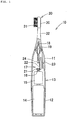
- an electric toothbrush 10 comprises a casing 13 also serving as a handle and having a structure partitioned into an upper casing 11 and a lower casing 12.
- the upper and lower casings 11, 12 are detachably joined.
- a battery 14 is contained, so that it can be replaced, inside the lower portion of the casing 13, a DC electric motor 15 is incorporated in the intermediate portion of the casing 13.
- the motor 15 can be switched ON and OFF with a switch (not shown in the figure) assembled with the casing 13.
- Conversion means 17 for converting the rotation movement of a rotation shaft 16 of the motor 15 into the linear movement in the vertical direction of the output shaft 18 is provided inside the upper portion of the casing 13.
- the output shaft 18 is provided so that it is able to move in the vertical direction through an upper wall portion of the casing 13 in the intermediate section thereof.
- a rubber cover 19 is provided in the upper end section of the casing 13 so as to prevent water or the like from penetrating from the sliding portion of the output shaft 18 and casing 13.
- a replaceable brush 20 is detachably mounted on the upper half of the output shaft 18 protruding upward from the casing 13.
- a first bevel gear 21 is fixedly mounted on the rotation shaft 16 of the motor 15.
- a second bevel gear 22, which is engaged with the first bevel gear 21, is provided, so that it can rotate about a shaft section 23, in the inner wall section of the upper casing 11.
- a slit for cam 25 is provided in the horizontal direction in the lower end section of the output shaft 18, and an engagement pin 24 extending inside the slit 25 is protruded in the eccentric position of the second bevel gear 22.
- the rotation movement of the rotation shaft 16 of the motor 15 around the center of the axis in the vertical direction is converted by the first and second bevel gears 21, 22 into the rotation movement of the shaft section 23 around the axis center in the horizontal direction, and this rotation movement is converted into back-and-forth linear movement of the output shaft 18 in the vertical direction via the slit 25 and engagement pin 24.
- the number of cog in the gears 21, 22 is set so that the back-and-forth linear movement (frequency of back-and-forth motion) of the output shaft 18 in the vertical direction within 1 min is within the mentioned range of frequency of back-and-forth motion. Furthermore, the eccentricity of the engagement pin 24 with respect to the shaft section 23 of the second bevel gear 22 is set so that the distance of movement of the replaceable brush 20 in the vertical direction (distance of movement of the tuft) is within the mentioned range of the distance of movement of the tuft.
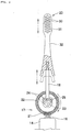
- the replaceable brush 20 has a well-known specification in which the tufted portion 31 is formed in the head 30 connecting neck portion 32 detachably connected the output shaft 18. Any shape of the head 30, number of tufts, and arrangement thereof can be set. Furthermore, a method by which the tufts constructed by the filaments are fixed into holes for tuft provided in the head by the anchor and fused by heat can be advantageously used as the method for fixing tufts. Furthermore, any material, diameter, length, or shape of the tip end of the filaments can be utilized. Moreover, filaments which constructed by one material or composite material may be utilized. If the filaments in which only the tip end is split into a plurality of portion are used, because the roots of filaments are stable, the motions can be sufficiently transmitted to the tips. Accordingly such a specification is preferred. Furthermore, because such filaments with split tips improve the plaque removal, it is preferred that the number of filaments with split tips be at least 30% of the total number of filaments.
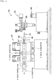
- the device 40 has a structure identical to that of the device described in Japanese Patent Publication No. H10-239304 .
- the device 40 for evaluating the electric toothbrush 10 comprises operation means 41 for operating the electric toothbrush 10 in the three directions: X axis direction (left-right direction), Y axis direction (up-down direction), and Z axis direction (forward-backward direction), and rotating in the ⁇ direction around the X axis, in the state where the electric toothbrush 10, which is to be tested, is held in the X axis direction, control means (not shown in the figure) for controlling the operation means 41 so that the electric toothbrush 10 held in the operation means 41 performs brushing by the desired brushing method, holding means 43 for holding a dental model 42 so that the position thereof can be controlled, so that the desired teeth of the dental model 42 face the tufted portion 31 of the electric toothbrush 10 held in the operation means 41, and measurement means 44 for measuring the brushing pressure of the electric toothbrush 10 on the dental model 42.
- the measurement means 44 measured the pressure (brushing pressure) acting upon the tufted portion 31 of the electric toothbrush 10 based on the output of a strain gage 45.
- the strain gage 45 has a well-known specification comprising a resistor from a metal or a semiconductor and is attached to the front surface of a support frame 47 of a holder 46 provided for securely holding the electric toothbrush 10 on the operation means 41.
- Electric toothbrushes of three types with the distance of movement of the tuft caused by back-and-forth linear movement of the tufted portion set at 0.5 mm, 1.0 mm, and 3.0 mm were used as the electric toothbrush. Furthermore, a replaceable brush was manufactured by arranging tufts in 3 rows, 23 tufts with a tuft hole diameter of 1.6 mm and filaments with a diameter of 0.160 mm and a length of 10 mm. The tip portions of the filaments were trimmed to flat and were end-rounded.
- the electric toothbrushes of the above-described three types were used for brushing the dental model 42 under the below-described conditions by changing the frequency of back-and-forth motion of the tufted portion per minute in 6 stages: 1,000, 2,000, 5,000, 7,000, 10,000, and 11,000, and the removal ratio of artificial plaque that was coated to the teeth of the dental model 42 was measured.
- the frequency of back-and-forth motion indicates the number of back-and-forth linear movements, where one back-and-forth movement of the tufted portion is counted as 1 cycle.
- the frequency of back-and-forth motion was adjusted by conducting voltage control of the electric toothbrush.
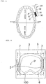
- the artificial plaque was coated on the 1st premolar A, second premolar B, and first molar C on the upper jaw side that were brushed in the dental model 42, the electric toothbrush 10 was driven at the prescribed frequency of back-and-forth motion, the brushing was conducted by moving the electric toothbrush from the first molar C to the first premolar A (forward) at a movement speed 3.16 mm/sec, under a brushing pressure of 150 g.
- a method for setting a interproximal portion 2 of a tooth 1 will be explained below.
- the buccal side surface of the tooth 1 downside from a gum 3 was picked up with a photographic means, and the center P of the rectangular frame 5, which is in contact with the outer shape of the standard image 4 of the tooth 1, was found.
- the reduced image 6 obtained by reducing the standard image 4 to 80% was generated and the two images 4 and 6 were superimposed so that the centers P thereof were superimposed.
- the standard image 4 was then delineated with lines 7 that touch the reduced image 6 and the region shown by hatching on the outside of the lines 7 was set as an interproximal portion 2.
- Table 1 Frequency of back-and-forth motions y (times) Distance of movement of tufts x (mm) Product of x and y Evaluation 2000 0.5 1000 ⁇ 2000 1 2000 ⁇ 5000 0.5 2500 ⁇ 1000 3 3000 ⁇ 7000 0.5 3500 ⁇ 5000 1 5000 ⁇ 10000 0.5 5000 ⁇ 11000 0.5 5500 ⁇ 2000 3 6000 ⁇ 7000 1 7000 ⁇ 10000 1 10000 ⁇ 5000 3 15000 ⁇ 7000 3 21000 ⁇
- the distance of movement of the tuft has to be decreased, for example, when the distance of movement of the tuft is set at 0.5 mm, it is preferred that the frequency of back-and-forth motion per minute be set within a comparatively narrow range of 10,000 to about 11,000.
- the range was set under a proviso that the plaque removal ratio is 42% or higher, and the following formula was obtained.
- y ax + b .
- a -3000, 10,000 ⁇ b ⁇ 12,500, x > 0.
- FIG. 7 demonstrates that the plaque removal ratio changed under the effect of the distance of movement of the tuft and frequency of back-and-forth motion, and at least when the distance of movement of the tuft is 0.5 mm to 3.0 mm and the frequency of back-and-forth motion is 2,000-10,000, it is preferred that the frequency of back-and-forth motion be set lower as the distance of movement of the tuft increases. Furthermore, in the case of a patient with gingivitis, sufficient plaque removal ratio can be ensured similarly to the common electric toothbrush by setting the frequency of back-and-forth motion appropriately, while avoiding the problem of damaging the gum by decreasing the distance of movement of the tuft.
Landscapes
- Health & Medical Sciences (AREA)
- Dentistry (AREA)
- Epidemiology (AREA)
- Life Sciences & Earth Sciences (AREA)
- Animal Behavior & Ethology (AREA)
- General Health & Medical Sciences (AREA)
- Public Health (AREA)
- Veterinary Medicine (AREA)
- Brushes (AREA)
Claims (2)
- Elektrische Zahnbürste aufweisend:Wandlungseinrichtungen (17) zum Wandeln einer Rotationsbewegung eines Motors (15) in eine lineare Hin-und-Her-Bewegung einer Abtriebswelle (18); undeine austauschbare Bürste (20), die lösbar an der Abtriebswelle (18) angebracht ist, wobei die austauschbare Bürste (20) aufweist:einen Halsabschnitt (32), der lösbar mit der Abtriebswelle (18) verbunden ist; undeinen Borstenbereich (31), der durch Befestigen mehrerer Borsten in einem mit dem Halsabschnitt (32) verbundenen Kopf (30) gebildet ist,wobei ein Bürsten durch eine lineare Hin-und-Her-Bewegung des Borstenbereichs (31) gemeinsam mit der austauschbaren Bürste (20) in eine axiale Richtung der Abtriebswelle (18) ermöglicht ist,wobei eine Strecke (mm) der Bewegung des Borstenbereichs (31) in einem Bereich von 0,5 bis 3,0 mm festgesetzt ist und eine Frequenz (Anzahl) der Hin-und-Her-Bewegung des Borstenbereichs (31) pro Minute im Bereich von 2000 bis 11000 festgesetzt ist, unddas Produkt aus der Bewegungsstrecke (mm) des Borstenbereichs und der Frequenz (Anzahl) der Hin-und-Her-Bewegung des Borstenbereichs (31) pro Minute im Bereich von 5000 bis 7000 festgesetzt ist.
- Elektrische Zahnbürste nach Anspruch 1, wobei Filamente verwendet werden, in denen Spitzenabschnitte von mindestens 30% oder mehr aller Borstenfilamente in mehrere Abschnitte aufgeteilt sind.
Applications Claiming Priority (2)
| Application Number | Priority Date | Filing Date | Title |
|---|---|---|---|
| JP2003177337 | 2003-06-20 | ||
| PCT/JP2004/008535 WO2004112536A1 (ja) | 2003-06-20 | 2004-06-17 | 電動歯ブラシ |
Publications (3)
| Publication Number | Publication Date |
|---|---|
| EP1639914A1 EP1639914A1 (de) | 2006-03-29 |
| EP1639914A4 EP1639914A4 (de) | 2008-03-26 |
| EP1639914B1 true EP1639914B1 (de) | 2017-05-17 |
Family
ID=33534954
Family Applications (1)
| Application Number | Title | Priority Date | Filing Date |
|---|---|---|---|
| EP04746050.6A Expired - Lifetime EP1639914B1 (de) | 2003-06-20 | 2004-06-17 | Elektrische zahnbürste |
Country Status (7)
| Country | Link |
|---|---|
| US (1) | US20070000079A1 (de) |
| EP (1) | EP1639914B1 (de) |
| JP (1) | JP4306681B2 (de) |
| CN (1) | CN100500052C (de) |
| CA (1) | CA2529773A1 (de) |
| ES (1) | ES2635269T3 (de) |
| WO (1) | WO2004112536A1 (de) |
Families Citing this family (9)
| Publication number | Priority date | Publication date | Assignee | Title |
|---|---|---|---|---|
| EP1905382A1 (de) | 2006-09-29 | 2008-04-02 | Trisa Holding AG | Elektrozahnbürste und Getriebe für eine Elektrozahnbürste |
| CN102596096B (zh) | 2009-08-17 | 2014-11-19 | 盛势达瑞士有限公司 | 振动频率调整装置和使用其的水流式口腔内清洗装置 |
| US9154025B2 (en) | 2010-07-23 | 2015-10-06 | Braun Gmbh | Personal care device |
| EP2410641A1 (de) * | 2010-07-23 | 2012-01-25 | Braun GmbH | Elektrischer Linearmotor |
| EP2420203B1 (de) | 2010-08-19 | 2019-10-23 | Braun GmbH | Resonanzmotoreinheit und Elektrogerät mit Resonanzmotoreinheit |
| CN202056272U (zh) * | 2011-03-17 | 2011-11-30 | 信利仪器(汕尾)有限公司 | 一种直线往复式驱动结构及清洁工具 |
| EP2550937B1 (de) | 2011-07-25 | 2014-02-26 | Braun GmbH | Magnetische Verbindung zwischen einem Zahnbürstengriff und einem Bürstenkopf |
| CN103703668B (zh) | 2011-07-25 | 2016-12-07 | 博朗有限公司 | 线性电动聚合物马达和具有所述线性电动聚合物马达的装置 |
| EP2550938B1 (de) | 2011-07-25 | 2015-01-14 | Braun GmbH | Mundpflegevorrichtung |
Citations (2)
| Publication number | Priority date | Publication date | Assignee | Title |
|---|---|---|---|---|
| US5448792A (en) * | 1993-05-28 | 1995-09-12 | U.S. Philips Corporation | Toothbrush |
| US20030084528A1 (en) * | 2001-11-06 | 2003-05-08 | The Procter & Gamble Company | Multi-motion toothbrush |
Family Cites Families (23)
| Publication number | Priority date | Publication date | Assignee | Title |
|---|---|---|---|---|
| US3375820A (en) * | 1965-12-15 | 1968-04-02 | Cavitron Corp | Method and apparatus for ultrasonic cleaning of teeth |
| US3828770A (en) * | 1971-02-26 | 1974-08-13 | Ultrasonic Systems | Ultrasonic method for cleaning teeth |
| US4192035A (en) * | 1978-11-08 | 1980-03-11 | Ultrasonic Plaque Control Laboratories, Inc. | Ultrasonic toothbrush |
| US5150492A (en) * | 1991-02-08 | 1992-09-29 | Suroff Leonard W | Ultrasonic toothbrush |
| DE19627752A1 (de) * | 1996-07-10 | 1998-01-15 | Braun Ag | Elektrische Zahnbürste |
| CN2294702Y (zh) * | 1997-01-29 | 1998-10-21 | 冯智勇 | 保健电动牙刷 |
| US6178579B1 (en) * | 1998-09-30 | 2001-01-30 | Dr. Johns Products, Ltd. | Electric toothbrush |
| US6138310A (en) * | 1999-04-23 | 2000-10-31 | Porper; Robert P. | Electric toothbrush having opposed bristle heads |
| US6496999B1 (en) * | 2000-02-02 | 2002-12-24 | John O. Butler Company | Toothbrush with bristle configuration adapted for cleaning tooth surfaces and interproximal areas |
| CN2424755Y (zh) * | 2000-04-13 | 2001-03-28 | 韩瑞雪 | 一种新型电动牙刷 |
| DE10105764A1 (de) * | 2001-02-08 | 2002-09-05 | Braun Gmbh | Elektrische Zahnbürste |
| US6581234B2 (en) * | 2001-04-02 | 2003-06-24 | Jin Po Lee | Dental brush unit comprising gear connections |
| JP3932903B2 (ja) * | 2001-06-14 | 2007-06-20 | 松下電工株式会社 | 電動歯ブラシ |
| US20030084525A1 (en) * | 2001-11-07 | 2003-05-08 | The Procter & Gamble Company | Complex motion toothbrush |
| US6725490B2 (en) * | 2001-11-06 | 2004-04-27 | The Procter & Gamble Company | Complex motion toothbrush |
| JP2003144229A (ja) * | 2001-11-14 | 2003-05-20 | Lion Corp | 歯ブラシ |
| US7725972B2 (en) * | 2001-11-20 | 2010-06-01 | Glaxosmithkline Consumer Gmbh & Co. Kg | Toothbrush |
| US7067945B2 (en) * | 2002-05-03 | 2006-06-27 | Koninklijke Philips Electronics N.V. | Apparatus for converting side-to-side driving motion to rotational motion with a spring assembly and system for tuning the spring assembly |
| US20030226223A1 (en) * | 2002-06-11 | 2003-12-11 | The Procter & Gamble Co. | High efficiency electric toothbrush |
| AU2003272336A1 (en) * | 2002-09-11 | 2004-04-30 | The Procter And Gamble Company | Multi-motion stainbrush |
| US7409741B2 (en) * | 2003-06-24 | 2008-08-12 | Dworzan William S | Toothbrush with tuned vibrating head |
| US7322066B2 (en) * | 2003-07-16 | 2008-01-29 | Church & Dwight Co., Inc. | Electric toothbrushes having movable, intermittently movable, and fixed bristles |
| JP4255452B2 (ja) * | 2004-05-28 | 2009-04-15 | フクバデンタル株式会社 | イオン歯ブラシ |
-
2004
- 2004-06-17 CA CA002529773A patent/CA2529773A1/en not_active Abandoned
- 2004-06-17 JP JP2005507229A patent/JP4306681B2/ja not_active Expired - Fee Related
- 2004-06-17 CN CNB2004800172483A patent/CN100500052C/zh not_active Expired - Fee Related
- 2004-06-17 EP EP04746050.6A patent/EP1639914B1/de not_active Expired - Lifetime
- 2004-06-17 US US10/561,542 patent/US20070000079A1/en not_active Abandoned
- 2004-06-17 WO PCT/JP2004/008535 patent/WO2004112536A1/ja not_active Ceased
- 2004-06-17 ES ES04746050.6T patent/ES2635269T3/es not_active Expired - Lifetime
Patent Citations (2)
| Publication number | Priority date | Publication date | Assignee | Title |
|---|---|---|---|---|
| US5448792A (en) * | 1993-05-28 | 1995-09-12 | U.S. Philips Corporation | Toothbrush |
| US20030084528A1 (en) * | 2001-11-06 | 2003-05-08 | The Procter & Gamble Company | Multi-motion toothbrush |
Also Published As
| Publication number | Publication date |
|---|---|
| JPWO2004112536A1 (ja) | 2006-07-20 |
| US20070000079A1 (en) | 2007-01-04 |
| WO2004112536A1 (ja) | 2004-12-29 |
| CN100500052C (zh) | 2009-06-17 |
| EP1639914A1 (de) | 2006-03-29 |
| CN1809300A (zh) | 2006-07-26 |
| ES2635269T3 (es) | 2017-10-03 |
| JP4306681B2 (ja) | 2009-08-05 |
| EP1639914A4 (de) | 2008-03-26 |
| CA2529773A1 (en) | 2004-12-29 |
Similar Documents
| Publication | Publication Date | Title |
|---|---|---|
| EP1713413B1 (de) | Modulare elektrische zahnbürsten | |
| US7356866B2 (en) | Modular electric toothbrushes | |
| EP2266433B1 (de) | Zahnbürste | |
| EP2929803B1 (de) | Kopf für ein Mundpflegehilfsmittel | |
| AU2002319928B2 (en) | Electro-motion toothbrush | |
| US20130091645A1 (en) | Electric Toothbrush | |
| WO2003082050A1 (en) | Powered toothbrush with vibrating section | |
| WO2017062833A1 (en) | Brushes useful for cleaning teeth and interdental spaces | |
| CN214761568U (zh) | 一种可视振动电动牙刷 | |
| CA1266158A (en) | Automatic cleaning device | |
| EP1639914A1 (de) | Elektrische zahnbürste | |
| KR101592857B1 (ko) | 치관 및 잇몸 세정용 전동칫솔 | |
| CN112043445B (zh) | 一种智能牙刷及其刷牙方法 | |
| CN112043446B (zh) | 一种智能洁牙器及其洁牙方法 | |
| HUP0201345A2 (en) | Electric toothbrush | |
| JP2002177304A (ja) | 電動歯間ブラシ | |
| JP2006055194A (ja) | 電動歯ブラシ | |
| KR101896895B1 (ko) | 구강 케어 기구용 헤드 | |
| RU2295318C2 (ru) | Модульная электрическая зубная щетка | |
| JPH0251321B2 (de) | ||
| HK1217883A1 (zh) | 口腔護理工具的頭部 | |
| HK1217886A1 (zh) | 用於口腔護理工具的頭部 | |
| HK1149460A (en) | Toothbrush |
Legal Events
| Date | Code | Title | Description |
|---|---|---|---|
| PUAI | Public reference made under article 153(3) epc to a published international application that has entered the european phase |
Free format text: ORIGINAL CODE: 0009012 |
|
| 17P | Request for examination filed |
Effective date: 20060110 |
|
| AK | Designated contracting states |
Kind code of ref document: A1 Designated state(s): AT BE BG CH CY CZ DE DK EE ES FI FR GB GR HU IE IT LI LU MC NL PL PT RO SE SI SK TR |
|
| DAX | Request for extension of the european patent (deleted) | ||
| A4 | Supplementary search report drawn up and despatched |
Effective date: 20080222 |
|
| 17Q | First examination report despatched |
Effective date: 20080715 |
|
| REG | Reference to a national code |
Ref country code: DE Ref legal event code: R079 Ref document number: 602004051272 Country of ref document: DE Free format text: PREVIOUS MAIN CLASS: A46B0013020000 Ipc: A61B0017340000 |
|
| GRAP | Despatch of communication of intention to grant a patent |
Free format text: ORIGINAL CODE: EPIDOSNIGR1 |
|
| RIC1 | Information provided on ipc code assigned before grant |
Ipc: A61B 17/34 20060101AFI20161117BHEP |
|
| INTG | Intention to grant announced |
Effective date: 20161213 |
|
| GRAS | Grant fee paid |
Free format text: ORIGINAL CODE: EPIDOSNIGR3 |
|
| GRAA | (expected) grant |
Free format text: ORIGINAL CODE: 0009210 |
|
| AK | Designated contracting states |
Kind code of ref document: B1 Designated state(s): AT BE BG CH CY CZ DE DK EE ES FI FR GB GR HU IE IT LI LU MC NL PL PT RO SE SI SK TR |
|
| REG | Reference to a national code |
Ref country code: GB Ref legal event code: FG4D |
|
| REG | Reference to a national code |
Ref country code: FR Ref legal event code: PLFP Year of fee payment: 14 |
|
| REG | Reference to a national code |
Ref country code: CH Ref legal event code: EP |
|
| REG | Reference to a national code |
Ref country code: IE Ref legal event code: FG4D |
|
| REG | Reference to a national code |
Ref country code: AT Ref legal event code: REF Ref document number: 893725 Country of ref document: AT Kind code of ref document: T Effective date: 20170615 |
|
| REG | Reference to a national code |
Ref country code: DE Ref legal event code: R096 Ref document number: 602004051272 Country of ref document: DE |
|
| REG | Reference to a national code |
Ref country code: NL Ref legal event code: FP |
|
| REG | Reference to a national code |
Ref country code: ES Ref legal event code: FG2A Ref document number: 2635269 Country of ref document: ES Kind code of ref document: T3 Effective date: 20171003 |
|
| REG | Reference to a national code |
Ref country code: AT Ref legal event code: MK05 Ref document number: 893725 Country of ref document: AT Kind code of ref document: T Effective date: 20170517 |
|
| PG25 | Lapsed in a contracting state [announced via postgrant information from national office to epo] |
Ref country code: AT Free format text: LAPSE BECAUSE OF FAILURE TO SUBMIT A TRANSLATION OF THE DESCRIPTION OR TO PAY THE FEE WITHIN THE PRESCRIBED TIME-LIMIT Effective date: 20170517 Ref country code: FI Free format text: LAPSE BECAUSE OF FAILURE TO SUBMIT A TRANSLATION OF THE DESCRIPTION OR TO PAY THE FEE WITHIN THE PRESCRIBED TIME-LIMIT Effective date: 20170517 Ref country code: GR Free format text: LAPSE BECAUSE OF FAILURE TO SUBMIT A TRANSLATION OF THE DESCRIPTION OR TO PAY THE FEE WITHIN THE PRESCRIBED TIME-LIMIT Effective date: 20170818 |
|
| PG25 | Lapsed in a contracting state [announced via postgrant information from national office to epo] |
Ref country code: PL Free format text: LAPSE BECAUSE OF FAILURE TO SUBMIT A TRANSLATION OF THE DESCRIPTION OR TO PAY THE FEE WITHIN THE PRESCRIBED TIME-LIMIT Effective date: 20170517 Ref country code: SE Free format text: LAPSE BECAUSE OF FAILURE TO SUBMIT A TRANSLATION OF THE DESCRIPTION OR TO PAY THE FEE WITHIN THE PRESCRIBED TIME-LIMIT Effective date: 20170517 Ref country code: BG Free format text: LAPSE BECAUSE OF FAILURE TO SUBMIT A TRANSLATION OF THE DESCRIPTION OR TO PAY THE FEE WITHIN THE PRESCRIBED TIME-LIMIT Effective date: 20170817 |
|
| PG25 | Lapsed in a contracting state [announced via postgrant information from national office to epo] |
Ref country code: EE Free format text: LAPSE BECAUSE OF FAILURE TO SUBMIT A TRANSLATION OF THE DESCRIPTION OR TO PAY THE FEE WITHIN THE PRESCRIBED TIME-LIMIT Effective date: 20170517 Ref country code: CZ Free format text: LAPSE BECAUSE OF FAILURE TO SUBMIT A TRANSLATION OF THE DESCRIPTION OR TO PAY THE FEE WITHIN THE PRESCRIBED TIME-LIMIT Effective date: 20170517 Ref country code: SK Free format text: LAPSE BECAUSE OF FAILURE TO SUBMIT A TRANSLATION OF THE DESCRIPTION OR TO PAY THE FEE WITHIN THE PRESCRIBED TIME-LIMIT Effective date: 20170517 Ref country code: DK Free format text: LAPSE BECAUSE OF FAILURE TO SUBMIT A TRANSLATION OF THE DESCRIPTION OR TO PAY THE FEE WITHIN THE PRESCRIBED TIME-LIMIT Effective date: 20170517 Ref country code: RO Free format text: LAPSE BECAUSE OF FAILURE TO SUBMIT A TRANSLATION OF THE DESCRIPTION OR TO PAY THE FEE WITHIN THE PRESCRIBED TIME-LIMIT Effective date: 20170517 |
|
| REG | Reference to a national code |
Ref country code: CH Ref legal event code: PL |
|
| REG | Reference to a national code |
Ref country code: DE Ref legal event code: R097 Ref document number: 602004051272 Country of ref document: DE |
|
| PG25 | Lapsed in a contracting state [announced via postgrant information from national office to epo] |
Ref country code: IT Free format text: LAPSE BECAUSE OF FAILURE TO SUBMIT A TRANSLATION OF THE DESCRIPTION OR TO PAY THE FEE WITHIN THE PRESCRIBED TIME-LIMIT Effective date: 20170517 |
|
| REG | Reference to a national code |
Ref country code: IE Ref legal event code: MM4A |
|
| PLBE | No opposition filed within time limit |
Free format text: ORIGINAL CODE: 0009261 |
|
| STAA | Information on the status of an ep patent application or granted ep patent |
Free format text: STATUS: NO OPPOSITION FILED WITHIN TIME LIMIT |
|
| 26N | No opposition filed |
Effective date: 20180220 |
|
| PG25 | Lapsed in a contracting state [announced via postgrant information from national office to epo] |
Ref country code: LU Free format text: LAPSE BECAUSE OF NON-PAYMENT OF DUE FEES Effective date: 20170617 Ref country code: IE Free format text: LAPSE BECAUSE OF NON-PAYMENT OF DUE FEES Effective date: 20170617 Ref country code: CH Free format text: LAPSE BECAUSE OF NON-PAYMENT OF DUE FEES Effective date: 20170630 Ref country code: LI Free format text: LAPSE BECAUSE OF NON-PAYMENT OF DUE FEES Effective date: 20170630 |
|
| REG | Reference to a national code |
Ref country code: FR Ref legal event code: PLFP Year of fee payment: 15 |
|
| PG25 | Lapsed in a contracting state [announced via postgrant information from national office to epo] |
Ref country code: SI Free format text: LAPSE BECAUSE OF FAILURE TO SUBMIT A TRANSLATION OF THE DESCRIPTION OR TO PAY THE FEE WITHIN THE PRESCRIBED TIME-LIMIT Effective date: 20170517 |
|
| REG | Reference to a national code |
Ref country code: BE Ref legal event code: MM Effective date: 20170630 |
|
| PG25 | Lapsed in a contracting state [announced via postgrant information from national office to epo] |
Ref country code: BE Free format text: LAPSE BECAUSE OF NON-PAYMENT OF DUE FEES Effective date: 20170630 |
|
| PG25 | Lapsed in a contracting state [announced via postgrant information from national office to epo] |
Ref country code: HU Free format text: LAPSE BECAUSE OF FAILURE TO SUBMIT A TRANSLATION OF THE DESCRIPTION OR TO PAY THE FEE WITHIN THE PRESCRIBED TIME-LIMIT; INVALID AB INITIO Effective date: 20040617 Ref country code: MC Free format text: LAPSE BECAUSE OF FAILURE TO SUBMIT A TRANSLATION OF THE DESCRIPTION OR TO PAY THE FEE WITHIN THE PRESCRIBED TIME-LIMIT Effective date: 20170517 |
|
| PG25 | Lapsed in a contracting state [announced via postgrant information from national office to epo] |
Ref country code: CY Free format text: LAPSE BECAUSE OF NON-PAYMENT OF DUE FEES Effective date: 20170517 |
|
| PG25 | Lapsed in a contracting state [announced via postgrant information from national office to epo] |
Ref country code: TR Free format text: LAPSE BECAUSE OF FAILURE TO SUBMIT A TRANSLATION OF THE DESCRIPTION OR TO PAY THE FEE WITHIN THE PRESCRIBED TIME-LIMIT Effective date: 20170517 |
|
| PG25 | Lapsed in a contracting state [announced via postgrant information from national office to epo] |
Ref country code: PT Free format text: LAPSE BECAUSE OF FAILURE TO SUBMIT A TRANSLATION OF THE DESCRIPTION OR TO PAY THE FEE WITHIN THE PRESCRIBED TIME-LIMIT Effective date: 20170517 |
|
| PGFP | Annual fee paid to national office [announced via postgrant information from national office to epo] |
Ref country code: NL Payment date: 20210621 Year of fee payment: 18 |
|
| PGFP | Annual fee paid to national office [announced via postgrant information from national office to epo] |
Ref country code: GB Payment date: 20220624 Year of fee payment: 19 Ref country code: DE Payment date: 20220621 Year of fee payment: 19 |
|
| PGFP | Annual fee paid to national office [announced via postgrant information from national office to epo] |
Ref country code: FR Payment date: 20220630 Year of fee payment: 19 |
|
| PGFP | Annual fee paid to national office [announced via postgrant information from national office to epo] |
Ref country code: ES Payment date: 20220719 Year of fee payment: 19 |
|
| REG | Reference to a national code |
Ref country code: NL Ref legal event code: MM Effective date: 20220701 |
|
| PG25 | Lapsed in a contracting state [announced via postgrant information from national office to epo] |
Ref country code: NL Free format text: LAPSE BECAUSE OF NON-PAYMENT OF DUE FEES Effective date: 20220701 |
|
| REG | Reference to a national code |
Ref country code: DE Ref legal event code: R119 Ref document number: 602004051272 Country of ref document: DE |
|
| GBPC | Gb: european patent ceased through non-payment of renewal fee |
Effective date: 20230617 |
|
| PG25 | Lapsed in a contracting state [announced via postgrant information from national office to epo] |
Ref country code: DE Free format text: LAPSE BECAUSE OF NON-PAYMENT OF DUE FEES Effective date: 20240103 Ref country code: GB Free format text: LAPSE BECAUSE OF NON-PAYMENT OF DUE FEES Effective date: 20230617 |
|
| PG25 | Lapsed in a contracting state [announced via postgrant information from national office to epo] |
Ref country code: FR Free format text: LAPSE BECAUSE OF NON-PAYMENT OF DUE FEES Effective date: 20230630 |
|
| REG | Reference to a national code |
Ref country code: ES Ref legal event code: FD2A Effective date: 20240730 |
|
| PG25 | Lapsed in a contracting state [announced via postgrant information from national office to epo] |
Ref country code: ES Free format text: LAPSE BECAUSE OF NON-PAYMENT OF DUE FEES Effective date: 20230618 |
|
| PG25 | Lapsed in a contracting state [announced via postgrant information from national office to epo] |
Ref country code: ES Free format text: LAPSE BECAUSE OF NON-PAYMENT OF DUE FEES Effective date: 20230618 |