EP1638751B1 - Verbesserungen in bezug auf austragvorrichtung - Google Patents
Verbesserungen in bezug auf austragvorrichtung Download PDFInfo
- Publication number
- EP1638751B1 EP1638751B1 EP04736772A EP04736772A EP1638751B1 EP 1638751 B1 EP1638751 B1 EP 1638751B1 EP 04736772 A EP04736772 A EP 04736772A EP 04736772 A EP04736772 A EP 04736772A EP 1638751 B1 EP1638751 B1 EP 1638751B1
- Authority
- EP
- European Patent Office
- Prior art keywords
- tubular outlet
- dispensing
- component
- configuration
- actuator
- Prior art date
- Legal status (The legal status is an assumption and is not a legal conclusion. Google has not performed a legal analysis and makes no representation as to the accuracy of the status listed.)
- Active
Links
Images


Classifications
-
- B—PERFORMING OPERATIONS; TRANSPORTING
- B65—CONVEYING; PACKING; STORING; HANDLING THIN OR FILAMENTARY MATERIAL
- B65D—CONTAINERS FOR STORAGE OR TRANSPORT OF ARTICLES OR MATERIALS, e.g. BAGS, BARRELS, BOTTLES, BOXES, CANS, CARTONS, CRATES, DRUMS, JARS, TANKS, HOPPERS, FORWARDING CONTAINERS; ACCESSORIES, CLOSURES, OR FITTINGS THEREFOR; PACKAGING ELEMENTS; PACKAGES
- B65D83/00—Containers or packages with special means for dispensing contents
- B65D83/14—Containers or packages with special means for dispensing contents for delivery of liquid or semi-liquid contents by internal gaseous pressure, i.e. aerosol containers comprising propellant for a product delivered by a propellant
- B65D83/16—Containers or packages with special means for dispensing contents for delivery of liquid or semi-liquid contents by internal gaseous pressure, i.e. aerosol containers comprising propellant for a product delivered by a propellant characterised by the actuating means
- B65D83/20—Containers or packages with special means for dispensing contents for delivery of liquid or semi-liquid contents by internal gaseous pressure, i.e. aerosol containers comprising propellant for a product delivered by a propellant characterised by the actuating means operated by manual action, e.g. button-type actuator or actuator caps
- B65D83/205—Actuator caps, or peripheral actuator skirts, attachable to the aerosol container
-
- B—PERFORMING OPERATIONS; TRANSPORTING
- B29—WORKING OF PLASTICS; WORKING OF SUBSTANCES IN A PLASTIC STATE IN GENERAL
- B29C—SHAPING OR JOINING OF PLASTICS; SHAPING OF MATERIAL IN A PLASTIC STATE, NOT OTHERWISE PROVIDED FOR; AFTER-TREATMENT OF THE SHAPED PRODUCTS, e.g. REPAIRING
- B29C45/00—Injection moulding, i.e. forcing the required volume of moulding material through a nozzle into a closed mould; Apparatus therefor
- B29C45/16—Making multilayered or multicoloured articles
- B29C45/1676—Making multilayered or multicoloured articles using a soft material and a rigid material, e.g. making articles with a sealing part
-
- B—PERFORMING OPERATIONS; TRANSPORTING
- B65—CONVEYING; PACKING; STORING; HANDLING THIN OR FILAMENTARY MATERIAL
- B65D—CONTAINERS FOR STORAGE OR TRANSPORT OF ARTICLES OR MATERIALS, e.g. BAGS, BARRELS, BOTTLES, BOXES, CANS, CARTONS, CRATES, DRUMS, JARS, TANKS, HOPPERS, FORWARDING CONTAINERS; ACCESSORIES, CLOSURES, OR FITTINGS THEREFOR; PACKAGING ELEMENTS; PACKAGES
- B65D47/00—Closures with filling and discharging, or with discharging, devices
- B65D47/04—Closures with discharging devices other than pumps
- B65D47/20—Closures with discharging devices other than pumps comprising hand-operated members for controlling discharge
- B65D47/2018—Closures with discharging devices other than pumps comprising hand-operated members for controlling discharge comprising a valve or like element which is opened or closed by deformation of the container or closure
- B65D47/2031—Closures with discharging devices other than pumps comprising hand-operated members for controlling discharge comprising a valve or like element which is opened or closed by deformation of the container or closure the element being formed by a slit, narrow opening or constrictable spout, the size of the outlet passage being able to be varied by increasing or decreasing the pressure
-
- B—PERFORMING OPERATIONS; TRANSPORTING
- B65—CONVEYING; PACKING; STORING; HANDLING THIN OR FILAMENTARY MATERIAL
- B65D—CONTAINERS FOR STORAGE OR TRANSPORT OF ARTICLES OR MATERIALS, e.g. BAGS, BARRELS, BOTTLES, BOXES, CANS, CARTONS, CRATES, DRUMS, JARS, TANKS, HOPPERS, FORWARDING CONTAINERS; ACCESSORIES, CLOSURES, OR FITTINGS THEREFOR; PACKAGING ELEMENTS; PACKAGES
- B65D83/00—Containers or packages with special means for dispensing contents
- B65D83/14—Containers or packages with special means for dispensing contents for delivery of liquid or semi-liquid contents by internal gaseous pressure, i.e. aerosol containers comprising propellant for a product delivered by a propellant
- B65D83/16—Containers or packages with special means for dispensing contents for delivery of liquid or semi-liquid contents by internal gaseous pressure, i.e. aerosol containers comprising propellant for a product delivered by a propellant characterised by the actuating means
-
- B—PERFORMING OPERATIONS; TRANSPORTING
- B65—CONVEYING; PACKING; STORING; HANDLING THIN OR FILAMENTARY MATERIAL
- B65D—CONTAINERS FOR STORAGE OR TRANSPORT OF ARTICLES OR MATERIALS, e.g. BAGS, BARRELS, BOTTLES, BOXES, CANS, CARTONS, CRATES, DRUMS, JARS, TANKS, HOPPERS, FORWARDING CONTAINERS; ACCESSORIES, CLOSURES, OR FITTINGS THEREFOR; PACKAGING ELEMENTS; PACKAGES
- B65D83/00—Containers or packages with special means for dispensing contents
- B65D83/14—Containers or packages with special means for dispensing contents for delivery of liquid or semi-liquid contents by internal gaseous pressure, i.e. aerosol containers comprising propellant for a product delivered by a propellant
- B65D83/75—Aerosol containers not provided for in groups B65D83/16 - B65D83/74
- B65D83/753—Aerosol containers not provided for in groups B65D83/16 - B65D83/74 characterised by details or accessories associated with outlets
- B65D83/7535—Outlet valves opened by the product to be delivered
-
- B—PERFORMING OPERATIONS; TRANSPORTING
- B29—WORKING OF PLASTICS; WORKING OF SUBSTANCES IN A PLASTIC STATE IN GENERAL
- B29C—SHAPING OR JOINING OF PLASTICS; SHAPING OF MATERIAL IN A PLASTIC STATE, NOT OTHERWISE PROVIDED FOR; AFTER-TREATMENT OF THE SHAPED PRODUCTS, e.g. REPAIRING
- B29C45/00—Injection moulding, i.e. forcing the required volume of moulding material through a nozzle into a closed mould; Apparatus therefor
- B29C45/16—Making multilayered or multicoloured articles
- B29C45/1676—Making multilayered or multicoloured articles using a soft material and a rigid material, e.g. making articles with a sealing part
- B29C2045/1678—Making multilayered or multicoloured articles using a soft material and a rigid material, e.g. making articles with a sealing part first moulding the soft material
Definitions
- This invention relates to a dispensing apparatus and an actuator cap, and furthermore to a process for the manufacture of dispensers for the dispensing of fluid products from containers.
- fluid products are packaged in containers from which aliquots of the product are dispensed as required.
- fluid products is meant in this context products that may be caused to flow by the application of pressure. Examples include liquids, both non-viscous and viscous, pastes, gels, foams, sauces and the like. Many such products are supplied in pressurised canisters. Typically, such products are packaged in a sealed container fitted with a dispensing valve. Some form of actuator is fitted to the container, often as a cap, the actuator including means for operating the valve and including an outlet through which the product is dispensed. Many products of this type are dispensed as foams or gels. Examples include many cosmetic, personal care or food products, such as shaving foams or gels, hair gels and mousses, sauces, as well as skincare products and many others.
- actuators for products of this type generally comprise a fluid conduit leading to an outlet opening, the fluid conduit being in fluid communication with the dispensing valve.
- the user depresses the actuator to actuate the valve and dispense the product, and releases the actuator once sufficient product has been dispensed.
- US 6,497,346 discloses dispensing apparatus comprising an elastically deformable nozzle that terminates with a dispensing slot, wherein the dispensing slot is openable by elastic deformation of the material of the nozzle.
- WO 00/26007 discloses dispensing apparatus comprising a nozzle formed by a substantially hard core and a substantially elastic envelope partially enclosing the core, such that part of the envelope that is in sealed contact with the core forms an elastically deformable closure for the nozzle.
- a major problem with known actuators of this type is that after the actuator is released and the valve closes, a certain amount of product may remain in the fluid conduit. This residual product may dry up and block the fluid conduit. Also, if the product is one that generates a foam upon reaching the atmosphere, the product may continue to ooze from the fluid conduit for an appreciable time after the valve closes. In addition, any product that remains in the fluid conduit will be dispensed next time that the actuator is used. In the meantime, that product may have deteriorated, or even become harmful.
- Other forms of product with which the invention is concerned include containers fitted with pump mechanisms by which material can be pumped through an outlet on depression of an actuator, and containers formed in flexible material so that manual squeezing of the container by a user urges material from the container through an outlet.
- the invention may be applicable to any product that is dispensed from a container by the application of pressure, however that pressure is generated.
- dispensing apparatus for a fluid product, said apparatus comprising a container having a tubular outlet, wherein the tubular outlet has a collapsed non-dispensing configuration and wherein the tubular outlet is elastically deformable, by the application of pressure to the tubular outlet, to an expanded dispensing configuration in which the fluid product is able to flow through the tubular outlet, characterised in that the tubular outlet is moulded in an open configuration and is at least partially encased in a more rigid material, the casing being arranged so as to hold the tubular outlet in its non-dispensing configuration.
- the tubular outlet constitutes a fluid conduit that is closed when the tubular outlet is in the collapsed, non-dispensing configuration and opened when the tubular outlet is in the expanded, dispensing configuration.
- the dispensing apparatus comprises a pressurised container fitted with a dispensing valve having a valve outlet, and an actuator in which the tubular outlet is formed, the actuator being engaged with the dispensing valve such that depression of the actuator opens the dispensing valve.
- the actuator preferably takes the form of a cap that is fitted to the container.
- an actuator cap adapted to engage a pressurised container fitted with a dispensing valve having a valve outlet
- the actuator cap comprising an actuator including a tubular outlet including a fluid conduit, wherein the tubular outlet has a collapsed non-dispensing configuration in which the fluid conduit is closed and wherein the tubular outlet is elastically deformable, by the application of pressure to the tubular outlet, to an expanded dispensing configuration in which the fluid conduit is opened, characterised in that the tubular outlet is moulded in an open configuration and is at least partially encased in a more rigid material, the casing being arranged so as to hold the tubular outlet in its non-dispensing configuration.
- the dispensing apparatus and actuator cap according to the invention are preferably arranged such that liquid product exits the container under pressure, in use, and this pressure is sufficient to elastically deform the tubular outlet to its expanded dispensing configuration.
- the fluid product thus preferably functions as a pressure medium that acts upon the tubular outlet to deform it from the collapsed to the expanded configuration. In other embodiments, however, an external force or pressure may be applied to the tubular outlet to deform it to the expanded configuration.
- the dispenser according to the invention is advantageous principally because the elastically deformable nature of the tubular outlet ensures that the outlet is automatically sealed when not in use. This reduces the amount of substance that remains in the outlet between uses, thereby reducing the likelihood that the outlet will become blocked. In addition, the outlet will become sealed almost simultaneously with the removal of pressure from within the outlet, thereby reducing the amount of substance that continues to be dispensed after the pressure is removed.
- the material of the casing preferably at least partially surrounds the tubular outlet, the casing material exerting sufficient pressure on the tubular outlet to retain the tubular outlet in its non-dispensing configuration until the liquid product flows under pressure from the container, whereupon the tubular outlet expands to the dispensing configuration.
- the tubular outlet is preferably formed by injection moulding in an elastomeric material.
- the assembly of tubular outlet and more rigid casing is preferably manufactured by two-stage injection moulding.
- the tubular outlet and the more rigid component can be manufactured by injection moulding as two separate components and assembled after moulding.
- the tubular outlet is preferably moulded first, and the casing of more rigid material then moulded about the tubular outlet. This is unusual, in that two-stage injection moulding processes involving materials that are relatively rigid and relatively flexible are usually carried out by moulding first the relatively rigid material, followed by moulding of the more flexible material.
- a process for the manufacture of dispensing apparatus for a liquid product comprising moulding a first component including a tubular outlet, the first component being moulded in a first, relatively less rigid material, and moulding a second component about the first component, the second component being moulded in a second, relatively more rigid material, the tubular outlet being elastically deformable, by the application of pressure to the tubular outlet, from the closed configuration to the open configuration, characterised in that the first component is moulded with the tubular outlet in an open configuration and moulding of the second component compresses the tubular outlet to a closed configuration.
- first, relatively less rigid, material that is suitable for the moulding of the first component is a thermoplastic elastomer.
- a second, relatively more rigid, material that is suitable for the moulding of the second component is polypropylene.
- the dispensing apparatus is arranged such that liquid product flowing into the tubular outlet above a certain pressure, in use, is sufficient to elastically deform the tubular outlet to its expanded dispensing configuration.
- the liquid product will be dispensed through the fluid conduit of the tubular outlet when the liquid product is supplied from the container to the fluid conduit above a certain pressure.
- the tubular outlet will revert back from its dispensing configuration, in which the fluid conduit is open, to its non-dispensing configuration, in which the fluid conduit is sealed. In this way, the fluid conduit will become sealed automatically when liquid product ceases to be supplied from the container to the fluid conduit.
- the dispensing apparatus may be arranged such that the entire fluid conduit is collapsed, and hence all fluid product within the fluid conduit is expelled, when the tubular outlet reverts back from its dispensing configuration to its non-dispensing configuration.
- the fluid conduit may include an enlarged portion which forms a sealed cavity within the tubular outlet in its non-dispensing configuration. A small amount of the liquid product will therefore remain within the cavity in the collapsed, non-dispensing configuration.
- the volume of the cavity is preferably significantly less than the volume of the fluid conduit in its dispensing configuration.
- the enlarged portion is formed with an inclined surface at its downstream end so as to facilitate deformation of the tubular outlet by the liquid product.
- the actuator itself comprises a portion of the cap that is movable relative to the remainder of the cap.
- the entire cap may be movable relative to the container.
- the actuator is preferably adapted to receive the valve stem so that the valve stem is in fluid communication with the fluid conduit, and depression of the actuator will depress the valve stem, thereby releasing liquid product from the container.
- the container and/or cap may include means for pumping liquid product from the container through the outlet.
- the container and/or cap may include a pump mechanism that pumps material through the outlet on depression of an actuator.
- the container may be formed in a flexible material so that manual squeezing of the container by a user urges liquid product from the container through the outlet.
- the cap may be adapted to engage the container in any suitable manner. Examples include a snap-fit engagement, a threaded engagement and a bayonet-type engagement. It will be appreciated, however, that other forms of engagement may be used.
- the tubular outlet is preferably formed in an elastomeric material, and most preferably a thermoplastic elastomeric material.
- the fluid conduit is preferably of generally constant cross-section along its length, and preferably has openings of substantially similar size at either end, thereby forming inlet and outlet openings.
- the fluid conduit may include an enlarged portion which forms a cavity within the tubular outlet when the tubular outlet is in the collapsed, non-dispensing configuration, as discussed above.
- the fluid conduit has a flattened cross-section and is elastically deformable along the minor axis of the flattened cross-section.
- the external surface of the tubular outlet may include a formation that is adapted to mate with a corresponding formation formed on the remainder of the cap.
- the fluid conduit ie the internal bore of the tubular outlet, and most preferably also the external surface of the tubular outlet, is of generally hexagonal cross-section. It will be appreciated, however, that many other cross-sectional shapes may be employed.
- the container may be generally conventional in form, eg comprising a canister of aluminium or the like fitted with a conventional dispensing valve. Again, it will be apparent to those skilled in the art that many other forms of container may be suitable for use in the invention.
- FIGS 1, 2 and 3 show an aerosol spray cap according to the invention.
- the aerosol spray cap comprises a cap component 10 and a nozzle component 20.
- the cap component 10 is formed in polypropylene, and the nozzle component 20 is formed in a thermoplastic elastomeric material.
- the aerosol spray cap is formed in a two-shot injection moulding process which is described in more detail below.
- the cap component 10 is generally dome-shaped with an open lower end (as viewed in Figure 1).
- the open lower end of the cap component 10 is adapted to fit closely about the upper end of an aerosol canister.
- the interior surface of the cap component 10 is formed with a shoulder that abuts the peripheral edge of the aerosol canister when the cap component 10 is engaged therewith.
- the cap component 10 comprises a central actuator portion 12 that is separated from the remainder of the cap component 10 on all sides save for a single connecting side that forms a hinge.
- the hinged side is at the front of the spray cap.
- the free end of the actuator 12 remote from the hinge may be depressed towards the lower end of the cap component 10 by finger pressure.
- the cap component 10 may actually be moulded with a frangible web of polypropylene that connects the free end of the actuator portion 12 to the remainder of the cap component 10. Such a web may prevent unintentional actuation of the aerosol during transportation and storage, and is broken when the actuator is used for the first time.
- the free end of the actuator 12 remote from the hinge includes a finger grip 14 comprising an array of circular openings. Between the finger grip 14 and the hinge, the actuator 12 includes an opening with a short tube 16 extending downwardly therefrom.
- the tube 16 has an open lower end (as viewed in Figure 3) that faces the lower end of the cap component 10.
- the lower end of the tube 16 is enlarged so as to create a shoulder that abuts the top of the valve stem of an aerosol valve fitted to the aerosol canister.
- the opening at the upper end of the tube 16 is in fluid communication with the nozzle component 20, as described in more detail below.
- the actuator 12 has an elongate recess in its upper surface (as viewed in Figures 1 and 3) which extends from the opening at the upper end of the tube 16 to an open front end at the external front surface of the actuator 12.
- the lower part of the recess is enlarged.
- the enlarged lower part of the recess accommodates the nozzle component 20.
- FIG. 4 shows the nozzle component 20 in an open state.
- the main body of the nozzle component 20 is formed as a slightly flattened tube with an inclined open end.
- the lower surface of the nozzle component 20 (as viewed in Figure 4) is formed with three downwardly-projecting conical studs 22.
- the open front end of the nozzle component 20 forms an outlet opening 24.
- the rear end (as viewed in Figure 4) of the nozzle component 20 is closed but an inlet opening is formed in the underside of the nozzle component 20, near the rear end.
- a fluid conduit is therefore formed between the inlet and outlet openings 26,24 when the nozzle component 20 is in its open state.
- the nozzle component 20 is moulded in its open state and then the cap component 10 is moulded about the nozzle component 20.
- the moulding process is a two-shot injection moulding process in which, firstly, the nozzle component 20 is injection moulded in a thermoplastic elastomeric material in its open state, as shown in Figure 4.
- the cap component 10 is then injection moulded in polypropylene directly about the nozzle component 20, with the inlet 26 of the nozzle component 20 in registration with the tube 16 of the actuator 12 and the front end of the nozzle component 20 flush with the front face of the actuator 12.
- the cap component 10 and nozzle component 20 are locked together by moulding of the polypropylene material around the studs 22.
- Application of the polypropylene material to the previously-moulded nozzle component 20 causes the nozzle component 20 to be compressed to a closed state (as shown in Figures 1 and 3).
- the absence of polypropylene material over the upper surface of the nozzle component 20 permits the nozzle component 20 to deform upwardly under pressure, as described below, thereby allowing the nozzle component to revert, at least partially, to the open state shown in Figure 4.
- the nozzle component 20 retains a "memory" of that state and this, combined with the fact that the nozzle component 20 is held in the closed state under compression, facilitates the return of the nozzle component 20 to the open state when pressure is applied to it by flow of material through the nozzle component 20.
- the upper surface of the nozzle component 20 may be completely covered by the material of the cap component 10, but the thickness of such material may be relatively small, thereby still permitting expansion and opening of the nozzle component 20.
- the aerosol spray cap is engaged with an aerosol canister so that the upper end of the aerosol valve stem is received within the lower end of the tube 16 of the cap component 10.
- downward finger pressure is applied to the finger grip 14, thereby depressing the actuator 12.
- Depression of the actuator 12 causes the valve stem also to be depressed, thereby allowing the canister contents to be released under pressure along the tube 16 of the cap component 10 and through the inlet opening 26 of the nozzle component 20.
- the pressure of the canister contents will cause the nozzle component 20 to deform and expand.
- the upper and lower walls of the nozzle component 20 will therefore separate so that the nozzle component 20 is deformed to its open state, as shown in Figure 4.
- the canister contents will pass along the fluid conduit of the nozzle component 20 and exit the aerosol spray cap, under pressure, through the outlet opening 24.
- finger pressure is removed from the finger grip 14, thereby causing the actuator 12 to revert to its relaxed position (the aerosol valve stem being biased upwards in conventional fashion).
- the actuator 12 As the valve stem rises, emission of the canister contents ceases.
- the pressure of the canister contents within the fluid conduit of the nozzle component 20 will almost instantly fall to a level where the upper wall of the nozzle component 20 will collapse back into contact with the lower wall, thereby closing the inlet opening 26 whilst simultaneously expelling any remaining material from the fluid conduit of the nozzle component 20. Build-up of dispensed product in the fluid conduit is thereby prevented.
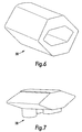
- Figures 6 and 7 show a second embodiment of a nozzle component 30 that is broadly similar in form and function to the nozzle component 20 described above.
- This embodiment of the nozzle component 30 differs from that previously described principally in that both the external surface of the nozzle component 30 and its internal bore are generally hexagonal in shape.
- the nozzle component 30 is moulded in the open configuration shown in Figure 6. When the remainder of an actuator cap is subsequently moulded (eg in polypropylene) about the nozzle component 30, the nozzle component 30 is compressed to the configuration shown in Figure 7.
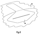
- Figure 8 shows a fragment of an aerosol spray cap that incorporates the nozzle component 30 of Figures 6 and 7.
- the nozzle component 30 occupies a correspondingly-shaped recess in the cap component 40, the material of the cap component 40 being moulded around the nozzle component 20, as described above.
- the upper surfaces of the nozzle component 30 and cap component 40 are substantially flush.
- the relatively rigid material (eg polypropylene) of the cap component 40 pinches the nozzle component 30 to the closed configuration, in which the upper and lower surfaces of its internal bore are pressed together, as shown in Figure 8.
- the central upper face of the nozzle component 30 is thus exposed, with the faces at either side being covered by a layer of more rigid material, the thickness of which reduces progressively from the outermost extremities of the nozzle component 30 towards the exposed central face.
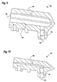
- Figures 9 and 10 show a third embodiment of a nozzle component 50 that is similar in form and function to the second embodiment of a nozzle component 30 described above.
- the third embodiment 50 is moulded in the open configuration shown in Figure 9, and has an inlet opening 52, an outlet opening 55 and a fluid conduit 53,54 that extends therebetween.
- the fluid conduit 53,54 comprises a generally cylindrical inlet portion 53 leading to an outlet portion 54 with a generally hexagonal cross-section.
- the inlet and outlet portions 53,54 are disposed generally perpendicular to one another.
- the third embodiment 50 includes a recess 56 in the interior surface of the upper wall of the nozzle component 50.
- the recess 56 is formed so as to define part of the outlet portion 54 of the fluid conduit 53,54.
- the recess 56 extends from an upstream end that is situated opposite the inlet portion 53 of the fluid conduit 53,54, along the longitudinal axis of the interior surface of the upper wall, to a downstream end that is situated a short distance from the outlet opening 55.
- the recess 56 has a generally rectangular cross-section, with the end wall of the recess 56 at the downstream end being inclined such that the depth of the recess 56 reduces gradually until it reaches that part of the outlet portion 54 that is situated immediately adjacent the outlet opening 55.
- the nozzle component 50 When the remainder of an actuator cap is subsequently moulded (eg in polypropylene) about the nozzle component 50, the nozzle component 50 is compressed to the closed configuration shown in Figure 10.
- the outlet portion 54 of the fluid conduit 53,54 is collapsed so that the interior surface of the upper wall of the nozzle component 50 is urged against the interior surface of the lower wall of the nozzle component 50.
- the outlet opening 55, and also that part of the outlet portion 54 that is disposed between the downstream end of the recess 56 and the outlet opening 55 are closed, and hence only the recess 56 remains in fluid communication with the inlet portion 53 of the fluid conduit 53,54.
- the recess 56 hence forms a cavity for the liquid product which has a significantly smaller volume than that of the outlet portion 54 of the fluid conduit 53,54 in the open configuration.
- the third embodiment 50 works in a very similar manner to the second embodiment 30. However, since the recess 56 will generally contain a small amount of the liquid product during use, less pressure is required to deform the nozzle component 50 into the open configuration.
- the third embodiment 50 therefore has a more reproducible dispensing action than the first and second embodiments 20,30, and is therefore suitable for those applications in which it is acceptable to leave a small amount of the liquid product in the fluid conduit of the nozzle component 50.
Claims (16)
- Verfahren zur Herstellung einer Spendervorrichtung, umfassend
Formen eines ersten Bauteils (20, 30, 50), das einen rohrförmigen Auslass (20, 30, 50) umfasst, wobei das erste Bauteil (20, 30, 50) aus einem ersten, relativ weniger starren Werkstoff geformt wird, und
Formen eines zweiten Bauteils (10, 40) um das erste Bauteil (20, 30, 50) herum, wobei das zweite Bauteil (10, 40) aus einem zweiten, relativ starreren Werkstoff geformt wird,
wobei der rohrförmige Auslass (20, 30, 50) durch Aufbringen einer Druckkraft auf denselben (20, 30, 50) von der Schließstellung zur Offenstellung elastisch verformbar ist,
dadurch gekennzeichnet,
dass das erste Bauteil (20, 30, 50) mit dem rohrförmigen Auslass (20, 30, 50) in einer Offenstellung geformt wird und das Formen des zweiten Bauteils (10, 40) den rohrförmigen Auslass (20, 30, 50) zur Schließstellung zusammendrückt. - Verfahren gemäß Anspruch 1, wobei der erste, weniger starre Werkstoff, der für das Formen des ersten Bauteils (20, 30, 50) geeignet ist, ein thermoplastisches Elastomer ist.
- Verfahren gemäß Anspruch 1 oder 2, wobei der zweite, relativ starrere Werkstoff, der zum Formen des zweiten Bauteils (10, 40) geeignet ist, ein Polypropylen ist.
- Spendervorrichtung für ein Fluid, umfassend einen Behälter, der einen rohrförmigen Auslass (20, 30, 50) aufweist, wobei der rohrförmige Auslass (20, 30, 50) eine zusammengefallene Schließstellung aufweist und wobei der rohrförmige Auslass (20, 30, 50) durch Aufbringen einer Druckkraft auf denselben zu der expandierten offenen Abgabestellung elastisch verformbar ist, bei der das Fluid durch den rohrförmigen Auslass (20, 30, 50) fließen kann,
dadurch gekennzeichnet,
dass der rohrförmige Auslass (20, 30, 50) in einer Offenstellung geformt ist und wenigstens teilweise von einem starreren Werkstoff (10, 40) umschlossen ist, wobei das Gehäuse (10, 40) derart ausgebildet ist, dass es den rohrförmigen Auslass (20, 30, 50) in seiner nicht spendenden Schließstellung hält. - Spendervorrichtung gemäß Anspruch 4, wobei die Spendervorrichtung derart ausgebildet ist, dass das Fluid bei Benutzung aus dem Behälter unter Druck austritt und dieser Druck ausreicht, den rohrförmigen Auslass (20, 30, 50) bis zu seiner weitesten Offenstellung elastisch zu verformen.
- Spendervorrichtung gemäß Anspruch 4 oder 5, wobei die gesamte Fluidleitung zusammengefallen ist und das gesamte sich in der Fluidleitung befindliche Fluid ausgestoßen wird, wenn der rohrförmige Auslass (20, 30, 50) von seiner Offenstellung in seine Schließstellung zurückkehrt.
- Spendervorrichtung gemäß Anspruch 4 oder 5, wobei die Fluidleitung einen vergrößerten Abschnitt umfasst, der einen abgedichteten Hohlraum (56) innerhalb des rohrförmigen Auslasses (20, 30, 50) bei dessen Schließstellung bildet.
- Spendervorrichtung gemäß einem der Ansprüche 4 bis 7, wobei der Behälter aus einem flexiblen Werkstoff geformt ist, so dass ein manuelles Zusammendrücken des Behälters durch einen Benutzer das Produkt aus dem Behälter durch den rohrförmigen Auslass (20, 30, 50) drückt.
- Spendervorrichtung gemäß einem der Ansprüche 4 bis 7, wobei die Spendervorrichtung Mittel zum Pumpen des Produkts aus dem Behälter durch den rohrförmigen Auslass (20, 30, 50) umfasst.
- Spendervorrichtung gemäß einem der Ansprüche 4 bis 7, wobei die Spendervorrichtung einen unter Druck stehenden Behälter, der mit einem Spenderventil ausgestattet ist, das einen Ventilauslass aufweist, und ein Betätigungselement umfasst, in dem der rohrförmige Auslass (20, 30, 50) ausgebildet ist, wobei das Betätigungselement mit dem Spenderventil derart in Verbindung steht, dass das drückende Betätigen des Betätigungselements das Spenderventil öffnet.
- Spendervorrichtung gemäß Anspruch 10, wobei das Betätigungselement die Form einer Kappe aufweist, die an dem Behälter befestigt ist.
- Betätigungselementkappe, die so ausgebildet ist, dass sie mit einem unter Druck stehenden Behälter verbindbar ist, der mit einem Spenderventil ausgestattet ist, das einen Ventilauslass aufweist, wobei die Betätigungselementkappe ein Betätigungselement umfasst, das einen rohrförmigen Auslass (20, 30, 50) umfasst, der eine Fluidleitung aufweist, wobei der rohrförmige Auslass (20, 30, 50) eine zusammengefallene Schließstellung aufweist, in der die Fluidleitung geschlossen ist, und wobei der rohrförmige Auslass (20, 30, 50) durch Aufbringen einer Druckkraft auf den rohrförmigen Auslass (20, 30, 50) zu einer expandierten Offenstellung, in der die Fluidleitung geöffnet ist, elastisch verformbar ist,
dadurch gekennzeichnet,
dass der rohrförmige Auslass (20, 30, 50) in einer Offenstellung geformt ist und wenigstens teilweise von einem starreren Werkstoff (10, 40) umschlossen ist, wobei das Gehäuse (10, 40) derart ausgebildet ist, dass es den rohrförmigen Auslass (20, 30, 50) in seiner Schließstellung hält. - Betätigungselementkappe gemäß Anspruch 12, wobei der rohrförmige Auslass (20, 30, 50) aus einem Elastomerwerkstoff hergestellt ist.
- Betätigungselementkappe gemäß Anspruch 12 oder 13, wobei die Fluidleitung einen flachen Querschnitt aufweist und entlang der Nebenachse des flachen Querschnitts elastisch verformbar ist.
- Betätigungselementkappe gemäß einem der Ansprüche 12 bis 14, wobei die Außenfläche des rohrförmigen Auslasses (20, 30, 50) eine Ausformung (22) umfasst, die so ausgebildet ist, dass sie mit einer zugehörigen Ausformung, die in der restlichen Kappe ausgebildet ist, zusammenpasst.
- Betätigungselementkappe gemäß einem der Ansprüche 12 bis 15, wobei das Betätigungselement einen Abschnitt der Kappe (12) umfasst, der relativ zu dem übrigen Teil der Kappe beweglich ist.
Applications Claiming Priority (2)
| Application Number | Priority Date | Filing Date | Title |
|---|---|---|---|
| GB0313676A GB2402712B (en) | 2003-06-13 | 2003-06-13 | Improvements relating to dispensing apparatus |
| PCT/GB2004/002549 WO2004110721A1 (en) | 2003-06-13 | 2004-06-14 | Improvements relating to dispensing apparatus |
Publications (2)
| Publication Number | Publication Date |
|---|---|
| EP1638751A1 EP1638751A1 (de) | 2006-03-29 |
| EP1638751B1 true EP1638751B1 (de) | 2007-12-12 |
Family
ID=27590017
Family Applications (1)
| Application Number | Title | Priority Date | Filing Date |
|---|---|---|---|
| EP04736772A Active EP1638751B1 (de) | 2003-06-13 | 2004-06-14 | Verbesserungen in bezug auf austragvorrichtung |
Country Status (8)
| Country | Link |
|---|---|
| US (1) | US7762435B2 (de) |
| EP (1) | EP1638751B1 (de) |
| AT (1) | ATE380642T1 (de) |
| DE (1) | DE602004010660T2 (de) |
| ES (1) | ES2298759T3 (de) |
| GB (1) | GB2402712B (de) |
| PT (1) | PT1638751E (de) |
| WO (1) | WO2004110721A1 (de) |
Families Citing this family (8)
| Publication number | Priority date | Publication date | Assignee | Title |
|---|---|---|---|---|
| DE102006012302A1 (de) * | 2006-03-15 | 2007-09-27 | Seaquist Perfect Dispensing Gmbh | Abgabevorrichtung |
| FR2908752B1 (fr) * | 2006-11-22 | 2009-01-30 | Rexam Dispensing Systems Sas | Bouton poussoir de pulverisation comprenant une buse invisible |
| FR2919589B1 (fr) * | 2007-08-01 | 2009-11-13 | Airlessystems Soc Par Actions | Clapet d'obturation et procede pour fabriquer un tel clapet. |
| EP2219975B1 (de) * | 2007-10-31 | 2014-07-09 | Plasticum Netherlands B.V. | Sprühkappe |
| US8881944B2 (en) * | 2008-06-30 | 2014-11-11 | S.C. Johnson & Son, Inc. | Overcap for and a method of actuating a volatile material dispenser |
| USD627224S1 (en) | 2009-10-08 | 2010-11-16 | S.C. Johnson & Son, Inc. | Overcap |
| NL2011199C2 (en) * | 2013-07-19 | 2015-01-21 | Jan Kelders Beheer B V | Dispenser and method for dispensing fluids from a liquid holder. |
| US10836541B2 (en) | 2017-11-27 | 2020-11-17 | Gateway Plastics, Inc. | Valve for a dispensing container |
Family Cites Families (16)
| Publication number | Priority date | Publication date | Assignee | Title |
|---|---|---|---|---|
| US729423A (en) * | 1900-11-03 | 1903-05-26 | Eugen Scheiber | Compression stop-cock. |
| US3684137A (en) * | 1970-08-07 | 1972-08-15 | Dean George Coleman | Closure assembly for collapsible tube |
| US3991916A (en) * | 1974-07-01 | 1976-11-16 | Bon F Del | Automatic closure device for the discharge of a foam product from a pressurized container |
| GB8526456D0 (en) | 1985-04-23 | 1985-11-27 | L S R Baby Products U K Ltd | Nipple |
| FR2650255B1 (fr) * | 1989-07-25 | 1992-01-10 | Oreal | Ensemble de distribution d'un ou plusieurs produit(s) sous forme de creme, de liquide ou de poudre, notamment de produits cosmetiques |
| FR2711620B1 (fr) * | 1993-10-21 | 1995-12-22 | Oreal | Ensemble de distribution équipé d'un organe de fermeture unidirectionnel. |
| US5588565A (en) * | 1994-02-14 | 1996-12-31 | Miller; Sidney H. | Valve for dispensing pressurized fluid through a flexible tube |
| US5501375A (en) * | 1994-05-12 | 1996-03-26 | Cenova Innovations & Produktions Ab | Dispenser valve for dispensing a pressurized liquid |
| ES2149854T3 (es) * | 1994-11-23 | 2000-11-16 | Oreal | Procedimiento de moldeo de un conjunto de distribucion equipado con un sistema de cierre. |
| WO1996019389A1 (fr) * | 1994-12-22 | 1996-06-27 | Pentel Kabushiki Kaisha | Conteneur de deversement |
| DE29508151U1 (de) * | 1995-05-17 | 1995-08-17 | Georg Menshen Gmbh & Co Kg | Schlitzventil zum Verschließen von Behältern |
| EP0856390B1 (de) * | 1997-01-22 | 2004-06-23 | Chisso Corporation | Verfahren zur Herstellung eines Verbundformgegenstandes aus thermoplastischen Harzen |
| FR2771078B1 (fr) * | 1997-11-14 | 2000-01-28 | Oreal | Organe reducteur d'ecoulement, notamment pour un recipient contenant un produit cosmetique et procede de fabrication |
| FR2773783B1 (fr) | 1998-01-22 | 2000-03-24 | Rexam Smt | Distributeur manuel auto-obturateur |
| FR2785222B1 (fr) * | 1998-11-02 | 2001-01-19 | Valois Sa | Procede de fabrication d'un obturateur, poussoir et tete de distribution incorporant un tel obturateur |
| NL1018233C2 (nl) | 2001-06-07 | 2002-12-10 | Itsac Nv | Afgiftetuit- en dopsamenstel. |
-
2003
- 2003-06-13 GB GB0313676A patent/GB2402712B/en not_active Expired - Fee Related
-
2004
- 2004-06-14 DE DE602004010660T patent/DE602004010660T2/de active Active
- 2004-06-14 PT PT04736772T patent/PT1638751E/pt unknown
- 2004-06-14 EP EP04736772A patent/EP1638751B1/de active Active
- 2004-06-14 WO PCT/GB2004/002549 patent/WO2004110721A1/en active IP Right Grant
- 2004-06-14 US US10/560,663 patent/US7762435B2/en active Active
- 2004-06-14 AT AT04736772T patent/ATE380642T1/de active
- 2004-06-14 ES ES04736772T patent/ES2298759T3/es active Active
Also Published As
| Publication number | Publication date |
|---|---|
| WO2004110721A1 (en) | 2004-12-23 |
| GB0313676D0 (en) | 2003-07-16 |
| EP1638751A1 (de) | 2006-03-29 |
| US7762435B2 (en) | 2010-07-27 |
| ES2298759T3 (es) | 2008-05-16 |
| GB2402712A (en) | 2004-12-15 |
| PT1638751E (pt) | 2008-03-17 |
| US20070138214A1 (en) | 2007-06-21 |
| GB2402712B (en) | 2006-04-19 |
| DE602004010660T2 (de) | 2008-12-11 |
| DE602004010660D1 (de) | 2008-01-24 |
| ATE380642T1 (de) | 2007-12-15 |
Similar Documents
| Publication | Publication Date | Title |
|---|---|---|
| US7775461B2 (en) | Nozzle devices | |
| US6460781B1 (en) | Sampling-type spraying device | |
| JP5546827B2 (ja) | 個人使用用の手持ち型ディスペンサー | |
| EP1503866B1 (de) | Flüssigkeitsspender | |
| EP1638751B1 (de) | Verbesserungen in bezug auf austragvorrichtung | |
| AU2003269097B2 (en) | Outlet device for a container or vessel | |
| ZA200505581B (en) | Dispenser pump |
Legal Events
| Date | Code | Title | Description |
|---|---|---|---|
| PUAI | Public reference made under article 153(3) epc to a published international application that has entered the european phase |
Free format text: ORIGINAL CODE: 0009012 |
|
| 17P | Request for examination filed |
Effective date: 20060113 |
|
| AK | Designated contracting states |
Kind code of ref document: A1 Designated state(s): AT BE BG CH CY CZ DE DK EE ES FI FR GB GR HU IE IT LI LU MC NL PL PT RO SE SI SK TR |
|
| DAX | Request for extension of the european patent (deleted) | ||
| GRAP | Despatch of communication of intention to grant a patent |
Free format text: ORIGINAL CODE: EPIDOSNIGR1 |
|
| RAP1 | Party data changed (applicant data changed or rights of an application transferred) |
Owner name: PLASTICUM UK LIMITED |
|
| GRAS | Grant fee paid |
Free format text: ORIGINAL CODE: EPIDOSNIGR3 |
|
| GRAA | (expected) grant |
Free format text: ORIGINAL CODE: 0009210 |
|
| AK | Designated contracting states |
Kind code of ref document: B1 Designated state(s): AT BE BG CH CY CZ DE DK EE ES FI FR GB GR HU IE IT LI LU MC NL PL PT RO SE SI SK TR |
|
| REG | Reference to a national code |
Ref country code: GB Ref legal event code: FG4D |
|
| REG | Reference to a national code |
Ref country code: CH Ref legal event code: EP |
|
| REG | Reference to a national code |
Ref country code: IE Ref legal event code: FG4D |
|
| REF | Corresponds to: |
Ref document number: 602004010660 Country of ref document: DE Date of ref document: 20080124 Kind code of ref document: P |
|
| REG | Reference to a national code |
Ref country code: PT Ref legal event code: SC4A Free format text: AVAILABILITY OF NATIONAL TRANSLATION Effective date: 20080304 |
|
| REG | Reference to a national code |
Ref country code: PT Ref legal event code: PC4A Owner name: PLASTICUM GROUP B.V., NL Effective date: 20080307 |
|
| REG | Reference to a national code |
Ref country code: CH Ref legal event code: NV Representative=s name: HEPP, WENGER & RYFFEL AG |
|
| RAP2 | Party data changed (patent owner data changed or rights of a patent transferred) |
Owner name: PLASTICUM GROUP B.V. |
|
| REG | Reference to a national code |
Ref country code: GR Ref legal event code: EP Ref document number: 20080400677 Country of ref document: GR |
|
| REG | Reference to a national code |
Ref country code: GB Ref legal event code: 732E |
|
| PG25 | Lapsed in a contracting state [announced via postgrant information from national office to epo] |
Ref country code: SE Free format text: LAPSE BECAUSE OF FAILURE TO SUBMIT A TRANSLATION OF THE DESCRIPTION OR TO PAY THE FEE WITHIN THE PRESCRIBED TIME-LIMIT Effective date: 20080312 |
|
| NLS | Nl: assignments of ep-patents |
Owner name: PLASTICUM GROUP B.V. Effective date: 20080307 |
|
| REG | Reference to a national code |
Ref country code: CH Ref legal event code: PUE Owner name: PLASTICUM GROUP B.V. Free format text: PLASTICUM UK LIMITED#2 BRAMBLE WAY CLOVER NOOK INDUSTRIAL ESTATE#SOMERCOTES ALFRETON DERBYSHIRE DE55 4RH (GB) -TRANSFER TO- PLASTICUM GROUP B.V.#ZEVENHEUVELENWEG 9#5048 AN TILBURG (NL) |
|
| REG | Reference to a national code |
Ref country code: ES Ref legal event code: FG2A Ref document number: 2298759 Country of ref document: ES Kind code of ref document: T3 |
|
| PG25 | Lapsed in a contracting state [announced via postgrant information from national office to epo] |
Ref country code: FI Free format text: LAPSE BECAUSE OF FAILURE TO SUBMIT A TRANSLATION OF THE DESCRIPTION OR TO PAY THE FEE WITHIN THE PRESCRIBED TIME-LIMIT Effective date: 20071212 Ref country code: SI Free format text: LAPSE BECAUSE OF FAILURE TO SUBMIT A TRANSLATION OF THE DESCRIPTION OR TO PAY THE FEE WITHIN THE PRESCRIBED TIME-LIMIT Effective date: 20071212 Ref country code: PL Free format text: LAPSE BECAUSE OF FAILURE TO SUBMIT A TRANSLATION OF THE DESCRIPTION OR TO PAY THE FEE WITHIN THE PRESCRIBED TIME-LIMIT Effective date: 20071212 |
|
| NLT2 | Nl: modifications (of names), taken from the european patent patent bulletin |
Owner name: PLASTICUM GROUP B.V. Effective date: 20080409 |
|
| PG25 | Lapsed in a contracting state [announced via postgrant information from national office to epo] |
Ref country code: CZ Free format text: LAPSE BECAUSE OF FAILURE TO SUBMIT A TRANSLATION OF THE DESCRIPTION OR TO PAY THE FEE WITHIN THE PRESCRIBED TIME-LIMIT Effective date: 20071212 |
|
| ET | Fr: translation filed | ||
| PG25 | Lapsed in a contracting state [announced via postgrant information from national office to epo] |
Ref country code: SK Free format text: LAPSE BECAUSE OF FAILURE TO SUBMIT A TRANSLATION OF THE DESCRIPTION OR TO PAY THE FEE WITHIN THE PRESCRIBED TIME-LIMIT Effective date: 20071212 Ref country code: RO Free format text: LAPSE BECAUSE OF FAILURE TO SUBMIT A TRANSLATION OF THE DESCRIPTION OR TO PAY THE FEE WITHIN THE PRESCRIBED TIME-LIMIT Effective date: 20071212 |
|
| PLBE | No opposition filed within time limit |
Free format text: ORIGINAL CODE: 0009261 |
|
| STAA | Information on the status of an ep patent application or granted ep patent |
Free format text: STATUS: NO OPPOSITION FILED WITHIN TIME LIMIT |
|
| PG25 | Lapsed in a contracting state [announced via postgrant information from national office to epo] |
Ref country code: DK Free format text: LAPSE BECAUSE OF FAILURE TO SUBMIT A TRANSLATION OF THE DESCRIPTION OR TO PAY THE FEE WITHIN THE PRESCRIBED TIME-LIMIT Effective date: 20071212 |
|
| 26N | No opposition filed |
Effective date: 20080915 |
|
| PG25 | Lapsed in a contracting state [announced via postgrant information from national office to epo] |
Ref country code: MC Free format text: LAPSE BECAUSE OF NON-PAYMENT OF DUE FEES Effective date: 20080630 |
|
| PG25 | Lapsed in a contracting state [announced via postgrant information from national office to epo] |
Ref country code: BG Free format text: LAPSE BECAUSE OF FAILURE TO SUBMIT A TRANSLATION OF THE DESCRIPTION OR TO PAY THE FEE WITHIN THE PRESCRIBED TIME-LIMIT Effective date: 20080312 Ref country code: EE Free format text: LAPSE BECAUSE OF FAILURE TO SUBMIT A TRANSLATION OF THE DESCRIPTION OR TO PAY THE FEE WITHIN THE PRESCRIBED TIME-LIMIT Effective date: 20071212 |
|
| PG25 | Lapsed in a contracting state [announced via postgrant information from national office to epo] |
Ref country code: CY Free format text: LAPSE BECAUSE OF FAILURE TO SUBMIT A TRANSLATION OF THE DESCRIPTION OR TO PAY THE FEE WITHIN THE PRESCRIBED TIME-LIMIT Effective date: 20071212 |
|
| PG25 | Lapsed in a contracting state [announced via postgrant information from national office to epo] |
Ref country code: IT Free format text: LAPSE BECAUSE OF NON-PAYMENT OF DUE FEES Effective date: 20080614 |
|
| PG25 | Lapsed in a contracting state [announced via postgrant information from national office to epo] |
Ref country code: LU Free format text: LAPSE BECAUSE OF NON-PAYMENT OF DUE FEES Effective date: 20080614 Ref country code: HU Free format text: LAPSE BECAUSE OF FAILURE TO SUBMIT A TRANSLATION OF THE DESCRIPTION OR TO PAY THE FEE WITHIN THE PRESCRIBED TIME-LIMIT Effective date: 20080613 |
|
| PGFP | Annual fee paid to national office [announced via postgrant information from national office to epo] |
Ref country code: IE Payment date: 20100407 Year of fee payment: 7 Ref country code: PT Payment date: 20100405 Year of fee payment: 7 |
|
| PG25 | Lapsed in a contracting state [announced via postgrant information from national office to epo] |
Ref country code: TR Free format text: LAPSE BECAUSE OF FAILURE TO SUBMIT A TRANSLATION OF THE DESCRIPTION OR TO PAY THE FEE WITHIN THE PRESCRIBED TIME-LIMIT Effective date: 20071212 |
|
| PGFP | Annual fee paid to national office [announced via postgrant information from national office to epo] |
Ref country code: GR Payment date: 20100608 Year of fee payment: 7 |
|
| PGRI | Patent reinstated in contracting state [announced from national office to epo] |
Ref country code: IT Effective date: 20110616 |
|
| REG | Reference to a national code |
Ref country code: PT Ref legal event code: MM4A Free format text: LAPSE DUE TO NON-PAYMENT OF FEES Effective date: 20111214 |
|
| PG25 | Lapsed in a contracting state [announced via postgrant information from national office to epo] |
Ref country code: PT Free format text: LAPSE BECAUSE OF NON-PAYMENT OF DUE FEES Effective date: 20111214 |
|
| REG | Reference to a national code |
Ref country code: GR Ref legal event code: ML Ref document number: 20080400677 Country of ref document: GR Effective date: 20120105 |
|
| REG | Reference to a national code |
Ref country code: IE Ref legal event code: MM4A |
|
| PG25 | Lapsed in a contracting state [announced via postgrant information from national office to epo] |
Ref country code: IE Free format text: LAPSE BECAUSE OF NON-PAYMENT OF DUE FEES Effective date: 20110614 |
|
| PG25 | Lapsed in a contracting state [announced via postgrant information from national office to epo] |
Ref country code: GR Free format text: LAPSE BECAUSE OF NON-PAYMENT OF DUE FEES Effective date: 20120105 |
|
| REG | Reference to a national code |
Ref country code: CH Ref legal event code: PVP |
|
| REG | Reference to a national code |
Ref country code: GB Ref legal event code: 732E Free format text: REGISTERED BETWEEN 20160303 AND 20160309 |
|
| REG | Reference to a national code |
Ref country code: GB Ref legal event code: 732E Free format text: REGISTERED BETWEEN 20160324 AND 20160330 |
|
| REG | Reference to a national code |
Ref country code: ES Ref legal event code: PC2A Owner name: WEENER PLASTICS NETHERLANDS B.V. Effective date: 20160614 |
|
| REG | Reference to a national code |
Ref country code: FR Ref legal event code: PLFP Year of fee payment: 13 |
|
| REG | Reference to a national code |
Ref country code: FR Ref legal event code: PLFP Year of fee payment: 14 |
|
| REG | Reference to a national code |
Ref country code: FR Ref legal event code: PLFP Year of fee payment: 15 |
|
| REG | Reference to a national code |
Ref country code: BE Ref legal event code: HC Owner name: WEENER PLASTICS NETHERLANDS B.V.; NL Free format text: DETAILS ASSIGNMENT: CHANGE OF OWNER(S), CHANGEMENT DE NOM DU PROPRIETAIRE; FORMER OWNER NAME: PLASTICUM NETHERLANDS B.V. Effective date: 20200203 Ref country code: BE Ref legal event code: RC Free format text: DETAILS PLEDGE: RIGHT OF PLEDGE, ETABLI Name of requester: ING BANK N.V. Effective date: 20160504 Ref country code: BE Ref legal event code: RF Free format text: DETAILS PLEDGE: RIGHT OF PLEDGE, SUPPRIME Name of requester: ING BANK N.V. Effective date: 20160630 |
|
| P01 | Opt-out of the competence of the unified patent court (upc) registered |
Effective date: 20230517 |
|
| PGFP | Annual fee paid to national office [announced via postgrant information from national office to epo] |
Ref country code: NL Payment date: 20230622 Year of fee payment: 20 Ref country code: FR Payment date: 20230620 Year of fee payment: 20 Ref country code: DE Payment date: 20230620 Year of fee payment: 20 |
|
| PGFP | Annual fee paid to national office [announced via postgrant information from national office to epo] |
Ref country code: AT Payment date: 20230616 Year of fee payment: 20 |
|
| PGFP | Annual fee paid to national office [announced via postgrant information from national office to epo] |
Ref country code: BE Payment date: 20230622 Year of fee payment: 20 |
|
| PGFP | Annual fee paid to national office [announced via postgrant information from national office to epo] |
Ref country code: IT Payment date: 20230630 Year of fee payment: 20 Ref country code: GB Payment date: 20230622 Year of fee payment: 20 Ref country code: ES Payment date: 20230719 Year of fee payment: 20 Ref country code: CH Payment date: 20230702 Year of fee payment: 20 |