EP1638121B1 - Electrical switch - Google Patents
Electrical switch Download PDFInfo
- Publication number
- EP1638121B1 EP1638121B1 EP04738184.3A EP04738184A EP1638121B1 EP 1638121 B1 EP1638121 B1 EP 1638121B1 EP 04738184 A EP04738184 A EP 04738184A EP 1638121 B1 EP1638121 B1 EP 1638121B1
- Authority
- EP
- European Patent Office
- Prior art keywords
- switch
- movable
- pothook
- current
- circuit
- Prior art date
- Legal status (The legal status is an assumption and is not a legal conclusion. Google has not performed a legal analysis and makes no representation as to the accuracy of the status listed.)
- Not-in-force
Links
Images


Classifications
-
- H—ELECTRICITY
- H01—ELECTRIC ELEMENTS
- H01H—ELECTRIC SWITCHES; RELAYS; SELECTORS; EMERGENCY PROTECTIVE DEVICES
- H01H50/00—Details of electromagnetic relays
- H01H50/16—Magnetic circuit arrangements
- H01H50/18—Movable parts of magnetic circuits, e.g. armature
- H01H50/32—Latching movable parts mechanically
-
- H—ELECTRICITY
- H01—ELECTRIC ELEMENTS
- H01H—ELECTRIC SWITCHES; RELAYS; SELECTORS; EMERGENCY PROTECTIVE DEVICES
- H01H50/00—Details of electromagnetic relays
- H01H50/54—Contact arrangements
- H01H50/60—Contact arrangements moving contact being rigidly combined with movable part of magnetic circuit
-
- H—ELECTRICITY
- H01—ELECTRIC ELEMENTS
- H01H—ELECTRIC SWITCHES; RELAYS; SELECTORS; EMERGENCY PROTECTIVE DEVICES
- H01H89/00—Combinations of two or more different basic types of electric switches, relays, selectors and emergency protective devices, not covered by any single one of the other main groups of this subclass
- H01H89/06—Combination of a manual reset circuit with a contactor, i.e. the same circuit controlled by both a protective and a remote control device
- H01H89/08—Combination of a manual reset circuit with a contactor, i.e. the same circuit controlled by both a protective and a remote control device with both devices using the same contact pair
-
- H—ELECTRICITY
- H01—ELECTRIC ELEMENTS
- H01H—ELECTRIC SWITCHES; RELAYS; SELECTORS; EMERGENCY PROTECTIVE DEVICES
- H01H50/00—Details of electromagnetic relays
- H01H50/54—Contact arrangements
- H01H50/546—Contact arrangements for contactors having bridging contacts
-
- H—ELECTRICITY
- H01—ELECTRIC ELEMENTS
- H01H—ELECTRIC SWITCHES; RELAYS; SELECTORS; EMERGENCY PROTECTIVE DEVICES
- H01H71/00—Details of the protective switches or relays covered by groups H01H73/00 - H01H83/00
- H01H71/10—Operating or release mechanisms
- H01H71/12—Automatic release mechanisms with or without manual release
- H01H71/24—Electromagnetic mechanisms
- H01H71/2436—Electromagnetic mechanisms with a holding and a releasing magnet, the holding force being limited due to saturation of the holding magnet
Description
- The present invention relates to an apparatus for connecting and breaking a circuit between a load and a power supply, which can be called an electrical switch and may be one single phase or three-phase switch. The present invention mainly introduces one three-phase electrical switch, whose load is a three-phase AC motor.
- In 1983, an Integral 32 combination electrical appliance was put on the market by Telemecanique (TE) Company in France, it represents the world's level today,
Fig.45 is view showing the structure of its switch portion, in which the connection and break of the switch are controlled by an attracting coil WI. A current limiting mechanism comprises a current limiter W3, a percussion bar B5, and astriking bar 65. Z1 denotes a tension spring, Z2 denotes a spring, the force of the tension spring Z1 is greater than that of Z2. When the attracting coil W1 is powered on, aconnection board 20 rises the spring Z2 so as to make the contact of the switch be closed, when the attracting coil W1 is powered off, the tension spring Z1 draws and presses Z2 so as to make the contact be disconnected. When an over-current flows through the switch, the current limiter W3 attracts percussion bar B5 to make thestriking bar 65 strike tension spring Z1, so that the movable contact and the stationary contact can be disconnected at a rapid speed. The bigger the current is, the faster the disconnection speed is. TE Company has been granted two Chinese Patents No.89108203 and No.89108574 , respectively. - Shanghai Electrical Power Science and Research Institute has developed the same product as TE Company, and has been granted Chinese
- Patent No.
95227387 . - The present inventor disassembled and analyzed the product manufactured by TE Company, and found out that it was too complicated to describe, at the same time, the product always keeps in the closed state as a contactor, and the power consumption is high. In contrast, the present switch is simpler, and the power consumption is lower, the present inventor has produced the sample.
- Document
US 4973929 discloses an electrical switch according to the preamble ofclaim 1. - To solve the problem described above, in accordance with one aspect of the present invention, there is provided an electrical switch for connecting and breaking the circuit, said electrical switch centralizes all the functions of the breaker, the contactor and the protective relay, it serves to connect, break and protect the circuit, not only to be operated frequently as the contactor, but also to break the larger short circuit current as the air switch. The switch has a small size, and a compact structure, in addition, it can save the electric energy.
- In order to achieve the above and other objects, the present invention provides an electrical switch for connecting and breaking the circuit including a connecting and breaking mechanism for connecting and breaking the circuit provided with at least a set of movable contacts and stationary contacts; and a electromagnetism drive mechanism for controlling the contacts to be actuated so as to realize closed circuit; a housing for accommodating the movable contact and stationary contact; an arc-extinguishing mechanism disposed in the housing and corresponded to the movable and stationary contact; a case connected to a base for accommodating the electromagnetism drive mechanism; a bedplate associated with the case; and a holding mechanism disposed on the bedplate for holding the contacts to connect the circuit after the contacts are connected, the holding mechanism is electromagnetic and has a set of electromagnetic attracting mechanism in which the movable iron core is made to be a pothook or a baffle mechanism, the movable iron core is attracted to make the contact mechanism hold the circuit connected when the electromagnetic attracting mechanism is powered on.
- In said electrical switch, the pothook or baffle of said holding mechanism keeps the switch closed by means of hitching or ramming the movable bolt, it further includes a coil, a conducting magnet plate, a bracket, and a tension spring; said pothook intersects the top end of the conducting magnet plate, and has an inclined plane at its hook so as to disconnect the movable bolt.
- In said electrical switch, said holding mechanism is an elasticity type, the pothook or baffle of said holding mechanism keeps the switch closed by means of elasticity, it further includes a spring, a stop button, and a reset button, said pothook or baffle abuts against the movable bolt.
- In said electrical switch, there is further provided with a current limiting mechanism disposed on the bedplate for detecting and limiting over-current, said over-current mechanism includes a set of electromagnet corresponding to each of phase circuit and a set of connecting rod mechanism connected with thereof, said connecting rod mechanism has a rod which can rapidly thrust aside the movable iron core of the holding mechanism when the over-current occurs, it includes a spring, a pushing plate, a pushing bar and a bracket.
- In said electrical switch, there is further provided with a selection switch mechanism disposed on the bedplate, said selection switch mechanism comprises a set of movable and stationary slide slices, in which the movable slide slice moves along with the turnbutton bar, said selection switch may move both in the rotary direction and in the vertical direction to control the operating state of said switch.
- In said electrical switch, there is further provided with a comprehensive protector, said comprehensive protector has a thermal element action means corresponding to each phase circuit, which can disconnect said switch when the over-current occurs, said comprehensive protector also has a phase failure mechanism corresponding to the main circuit, which can disconnect said switch in detecting the phase failure.
- Said switch is a combination type one, it comprises a switch portion and a protection portion, which will be described with reference to
Fig.10, 11 and17 , it may be a selective type or a nonselective type depending on whether there is a selection switch, the selective type employs the circuit shown asFig.1 , while the nonselective type employs the circuit shown asFig.2 or Fig.3 . - Said switch portion includes a contact and closing mechanism, a holding mechanism using a pothook or a baffle, a limiting current mechanism, a connecting and supporting mechanism and a selection switch mechanism.
- Said protection portion includes an overload protection mechanism, an over-current protection mechanism, a phase failure protection mechanism and a reset mechanism.
- Now, the operation of the switch will be described in details below.
- When the attracting coil W1 is powered on, the movable and stationary iron cores and the contacts are closed to make the holding coil W2 be electrified so as to attract the pothook E1, which can hook or repel the
movable bolt 19. At this time, though the coil W1 is powered off, the closing state is maintained by the coil W2 attracting the pothook E1, when it needs to disconnect the switch, the coil W2 is powered off, the pothook E1 rapidly breaks away themovable bolt 19 by a tensile force of the tension spring Z1 and a component force of the spring Z2. - When the pothook E1 breaks away the
movable bolt 19, the switch trips to make the movable iron core and the movable contacted and the stationary iron core and the stationary contact are rapidly separated from each other due to the spring Z2. - When the over-current occurs in the switch, the selection switch ejects immediately to turn off the switch K2, K3 and SA, and strikes the pothook E1 to disconnect from the hook so as to turn off the switch. The switch can be turned on only when the reset button of the selection switch is pressed.
- When the overload or over-current occurs in the switch, the protection mechanism breaks away the contact K1 to make the coil W2 be powered off and make the switch trip. The switch can be turned on again only when the protection mechanism is reset.
- Generally, the air switch is manually operated, its disconnection capacity is high (as an example of the switch 32A-400V, it has a disconnection capacity of 50000A as 1562 times as its rated current), but its lifespan is short, and it is difficult to start frequently. In contrast, since the contactor is electrically operated, its lifespan is long, it can be started frequently, but it only has a disconnection capacity as 10 times as its rated current.
- The reason why the disconnection capacity of the air switch is higher than that of the contactor is mainly that its disconnection speed is faster. The present inventor thinks that the reason why the disconnection speed of the contactor is slower has two factors: the one is that the contactor is heavier than the air switch in weight, the other one is mainly that there is magnetic remanence in the contactor when it is powered off instantly.
- At present, it is necessary to have the following functions in the electrical machine controlling system, that is, a overload protection, a short-circuit protection, a separation control, a rapid and easy control. These functions are generally carried out through the air switch, the contactor and the overload relay. The switch has all above functions, when it is turned on, the coil W1 is turned off immediately, and the magnetic remanence is small.
- Compared with said product, the switch has many following advantages: 1) the switch has a small size, and a simple structure, it can be near-controlled, be stopped and be remote-controlled by the selection switch, its operation is convenient and flexible; 2) the holding coil has a capacity less 5% than that of the attracting coil, and it saves energy; 3) since the switch employs the pothook structure, the pressure of its contact keeps stable, it is different from the conventional attracting coil which is often affected by the voltage variation of the power network which fluctuate in a sine wave forms, so the contact can be easily damaged; 4) the over-current action of the switch is short, and the response speed is rapid.
- In particular, the switch has a good practical effect, though it is said that the product manufactured by TE has a disconnection capacity of 50KA, it is infrequency in practice. For example, the maximum short circuit current in the transformer of 560KVA is only 16.7KA, and that of the transformer of 1800KVA is only 48KA. In practice, the switch may usually be partial short, sometimes the short circuit current is several times more than the rated current. It is impossible to make the striking bar of the product manufactured by TE be actuated, or make the breaker of the starter in the compact motor be actuated, in contrast, it can make the loop voltage on the attracting coil drop, they will be disconnected because the attracting force is smaller than the feedback force. Since some certain attracting forces also produce in the coil, the disconnection speed is slow, the contact tends to be turned out due to the pulling arc. Sometimes, though the load is not shorted, the voltage on the power network is low, said contact of the switch also be easily damaged.
- Since the present switch employs the tripping disconnection mechanism, its disconnection speed is mainly affected by the feedback force, even if the trip occurs in the holding coil due to the dropping voltage, the disconnection speed keeps constant, accordingly, the aforesaid problems do exist at all, therefore, the present switch is more practical and more reliable.
- Since the present switch has a structure in which it has a breakaway mechanism using winding, in which the magnetic remanence being so small to be negligent, meanwhile, its feedback force may be designed to be large. The action of the limiting current mechanism may be rapid. Therefore, it can break the large short circuit current as an air switch while it saves the energy.
- The above and other objects, features and advantages of the present invention will become clearer from the following description of the specific preferred embodiments with reference to the attached drawings, in which:
-
Fig.1 is a view showing the circuit diagram of a selective electrical switch; -
Fig.2 is a view showing the circuit diagram of a nonselective electrical switch; -
Fig.3 is a view showing the circuit diagram of a resilience -holding electrical switch with electrical actuation; -
Fig.4(a) is a view schematically showing a state after the selective switch is closed; -
Fig.4(b) is a view schematically showing a state after the selective switch is disconnected; -
Fig.4(c) is a view showing the action path of the selective switch; -
Fig.5 is a view schematically showing the structure of the movable slide slice shown inFig.4(a) and Fig.4(b) ; -
Fig.6 is a view schematically showing the structure of the fixed slide slice shown inFig.4(a) and Fig.4(b) ; -
Fig.7 is a view schematically showing the structure of the turn-button bar shown inFig.4(a) and Fig.4(b) ; -
Fig.8 is a view schematically showing the structure of the elastic baffle shown inFig.4(a) and Fig.4(b) ; -
Fig.9 is a view schematically showing the operation position of the selective switch, in whichFig.9(a) is a state of being remote-controlled,Fig.9(b) is a state of being stopped,Fig.9(c) is a state of being directly connected; -
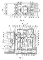
Fig.10 is a top view showing the structure of the vertical bolt switch; -
Fig.11 is a section cross view showing the structure of the pothook switch; -
Fig.12 is a section cross view showing the structure of the baffle switch; -
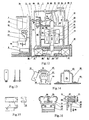
Fig.13 is a view schematically showing the structure of the movable bolt shown inFig.11 andFig.12 ; -
Fig.14 is a view schematically showing the structure of the holding mechanism shown inFig.11 ; -
Fig.15 is a view schematically showing the structure of the pothook show inFig.11 ; -
Fig.16 is a view schematically showing the structure of the limiting current mechanism shown inFig.11 andFig.12 ; -
Fig.17 is a section cross view showing the structure of the electrical switch implemented according to the present invention; -
Fig.18 is a view schematically showing the structure of the switch in which the contact is positioned on its top end; -
Fig.18 (a) is a view showing the circuit diagram of the structure of the electronic tripper; -
Fig.19 is a view schematically showing the structure of the nonselective switch in which the contact is positioned on its top end; -
Fig.20 is a top view and cross section view showing the structure of the side hook type electrical switch, respectively; -
Fig.21 is a view schematically showing the structure of the single contact side hook type electrical switch; -
Fig.22 is a cross section view showing the structure of the side hook type electrical switch shown inFig.20 ; -
Fig.23 is a view schematically showing the structure of the holding mechanism of the side hook type electrical switch shown inFig.20 andFig.22 ; -
Fig.24 is a view schematically showing the structure of one current limiter shown asFig.20 ; -
Fig.25 is a view schematically showing the structure of another current limiter shown asFig.20 ; -
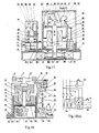
Fig.26 is a view schematically showing the structure of the resilience-holding mechanical switch with electrical actuation; -
Fig.27 is a view schematically showing the pothook coupled with the movable bolt in the resilience-holding switch; -
Fig.28 is a view showing the shape of the connecting shaft in the switch shown asFig.26 ; -
Fig.29 is a view schematically showing the structure of one mechanical-electrical protector; -
Fig.30 is a view schematically showing the structure of another one mechanical-electrical protector; -
Fig.31 is a view schematically showing the structure of the contact of the mechanical-electrical protector shown inFig.30 ; -
Fig.32 is a view showing a state after the over-current occurs in the protector shown inFig.30 ; -
Fig.33 is a view showing the phase failure control circuit of the protector shown inFig.29 ; -
Fig.34 is a view schematically showing the structure of the connecting shaft and compensation slice in the protector shown inFig.30 ; -
Fig.35 is a view schematically showing the element in assembly of the protector shown inFig.30 ; -
Fig.36 is a view schematically showing a state after the tripper shown inFig.30 is tripped; -
Fig.37 is a view schematically showing the structure of the overload bar in the protector shown inFig.30 ; -
Fig.38 is a view schematically showing the structure of the bracket in the protector shown inFig.30 ; -
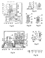
Fig.39 is a view schematically showing the structure of the movable arc contact; -
Fig.40 is a view schematically showing the structure of the V-shaped contact; -
Fig.41 is a view schematically showing the structure of the switch with a protective fuse; -
Fig.42 is a view schematically showing the structure of one switch in which the movable iron core has separated from the movable bolt; -
Fig.43 is a view schematically showing the structure of another switch in which the movable iron core has separated from the movable bolt; -
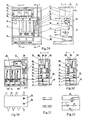
Fig.44 is a view schematically showing the structure of the impacting switch; -
Fig.45 is a principle diagram showing the structure of the switch produced by TE Company; -
Fig.46 is a view schematically showing a state in which the nonselective switch indicates the over-current and breaks away, the reset mechanism resets; -
Fig.47 is a view schematically showing a state in which the nonselective switch indicates the over-current and breaks away, the reset mechanism feedbacks; -
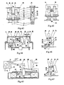
Fig.48 is a front view showing the switch according to one preferred embodiment of the present invention, on which the assistant contact is disposed; -
Fig.49 is a top view showing the switch shown inFig.48 , in which it has the assistant contact and the slide way; -
Fig.50 is a cross section view showing the structure of the switch shown inFig.48 ; -
Fig.51 is a view showing the electrical circuit of the switch shown inFig.48 ; -
Fig.52 is a side view showing the switch according to one preferred embodiment of the present invention; -
Fig.53 is a view schematically showing the position of the turnbutton when the switch shown inFig.52 is turned on; -
Fig.54 is a view schematically showing the position of the turnbutton when the switch shown inFig.52 is turned off; -
Fig.55 is a view schematically showing the connection and break of the circuit in the switch shown inFig.52 ; -
Fig.56 is a view schematically showing the structure of one current limiter mechanism; -
Fig.57 is a view schematically showing the structure of the attracting iron in the switch shown inFig.48, 49, 50 and52 ; -
Fig.58 is a view schematically showing the structure of the pushing bar in the switch shown inFig.48, 49, 50 and52 ; -
Fig.59 is a view schematically showing the structure of the insulating bracket. - The electrical switch according to the present invention will hereinafter be described in details by reference to the attached drawings.
-
Fig.1 is a circuit diagram shows one of the features of the present invention, in which after the switch is attracted and closed by means of the contact inside the switch, the circuit can assure the attracting coil to be powered off immediately, while can keep the holding coil be powered on so as to be on a self-protected state, if the switch is selected to be operated by the remote button, it can reduce one self-protection wire compared with the contactor, therefore, it is simple. -
Fig.1 shows one preferred circuit of the selective electrical switch, in which the elements and the circuit in the switch are disposed in the large broken line block, A, B, C are input source terminals respectively, a, b, c are input load terminals respectively, x1, x11, x2, x22 are output assistant contact terminals respectively, L, N are control source terminals, W1, W2 are provided at control terminals, K is the main contact and the assistant contact of the switch, W1 represents attracting coil, W3 represents a coil for over-current control mechanism, there is a comprehensive protector in the Z block, some comprehensive protectors contain the over-current control mechanism, a holding coil mechanism includes a holding coil W2, a rectification element, a continuation current element and a display element etc, which are all assembled on the element board EJ, there is a selective switch in h block. The attracting coil in the circuit also uses a DC source. The other kind of switch may employ the circuit shown inFig.2 or Fig.3 . - The electrical switch includes the selective switch and the nonselective switch, in which the operation of the selective switch depends on the selection switch.
- The selective switch is one of the features of the present invention, it has two functions of selecting the operation state and breaking the electrical circuit, and has a rotary action and a vertical action.
-
Fig.4(a) and Fig.4(b) are views schematically showing a structure of the selective switch, portion 1 h inFig.1 is a block diagram showing its circuit, it has three switch K2, K3, SA, also includes aturnbutton 2 andturnbutton bar 26. There is a bowl-shapedring 27 in theturnbutton bar 26 in which its top end is flat, its bottom end is round, as shownFig.7 . Z4, Z5 represent springs, thereference number 28 represents a branch pipe, thereference number 29 represents a movable slide slice, in which an elongated hole matched with theturnbutton bar 26, a rim and a contact area are sequentially arranged on the middle portion of themovable slide slice 29, and the movable contacts d1, d2 are disposed on themovable slide slice 29. As shownFig.5 , the buttons on two sides of themovable slide slice 29 are to limit the rotary range. Thereference number 30 represents the fixed slide slice, in which a hole passing throughring 27, a cog circle, and a contact area are sequentially arranged on the middle portion of the fixedslide slice 30, and the fixed contacts f1, f2, f3 and f4 are disposed on the fixedslide slice 30, the buttons on its two sides are to fix these above elements, as shownFig.6 . There are grooves among these contacts to increase the creepage distance. The rims of the movable and fixed slide slices fit with each other to adjust the gear. Thereference number 32 represents a pushing block made of elastic material, as shownFig.8 . - While the selective switch being assembled, the
movable slide slice 29, the spring Z4 and the pushingshield 32, whose front ends are blocked by the side of theturnbutton 26, their back ends are supported by thepad 33 which is riveted on theturnbutton bar 26, are muff-coupled in serial on theturnbutton bar 26. The back end of the spring Z4 may be directly blocked by thebracket 88. Themovable slide slice 29 may be disposed on the back end of the spring Z4, also may be directly blocked by the bracket88. Themovable slide slice 29 can move in the direction of the elastic force of the spring Z4, themovable slide slice 29 and the pushingblock 32 can rotate along with theturnbutton bar 26. Then, theturnbutton bar 26 passes through the fixedslide slice 30, and is fixed on thebracket 88 by the fixedmember 31 and thebranch pipe 28. After being sleeved on the spring Z5, theturnbutton bar 26 is fixed on thebedplate 68 of the switch, as shownFig.4(a) and 4(b) . - The selective switch has three-position type and four-position type, whose operation path is shown as
Fig.4(c) , it can rotate in the direction shown as the arrow in the figure, and select the operation state, the operation state of each block position follows as: - D1 remote control: when the selective switch directs to this position, K2, K3 are turned on, SA is turned off. At this time, the switch is only remote controlled, turned on or stopped.
- D2 stop: when the selective switch directs to this position, K2, K3 and SA are all turned off, the power supply is controlled by the switch, and the switch is powered off.
- D3 direct connection: when the selective switch directs to this position, K2 and SA are turned on, the switch is powered on.
- D4 direct lock: only the four-position type selective switch has a direct connection locking position and the pushing
block 32. When the selective switch turns from the direct connection position to the direct connection locking position, K2, K3 and SA are all turned off, a pothook E1 is opposed against the pushingblock 32 to lock themovable bolt 19 so as to make the switch closed such that the pushing block can maintain in the holding state. - The connecting and breaking state of the three-position type selective switch in every blocking position is shown as
Fig.9 , in which (a) indicates the remote control, (b) indicates stop, (c) indicates the direct connection. - The nonselective electrical switch does not have a selective switch, and it employs the circuit shown as
Fig.2 . -
Fig.10 is a top view showing the structure of the vertical bolt switch, including the switch portion and the comprehensive protection portion. The switch portion has a current limiter.Fig.11 is a section cross view showing the closed state of the switch maintained by the pothook mechanism holding switch;Fig.12 is a section cross view showing the closed state of the switch maintained by the baffle mechanism holding switch, all of which are applied to the circuit shown asFig.1 , which will be explained respectively as below. - The mechanism includes a attracting coil W1, a
stationary iron core 15, astationary contact 17, amovable contact 14, a guiding arc slice89 and aarc extinguisher 6, in which the contact mechanism uses a repulsion force type. Themovable iron core 16 and themovable bolt 19 are connected together with theconnection board 20, the insulatingconnection frame 21 and themovable contact 14. - While the coil W1 is powered on, the
movable iron core 16 is attracted to make themovable contact 14, themovable bolt 19, theconnection board 20 and the insulatingconnection frame 21 move along the direction shown as F1, therefore, themovable iron core 16 and themovable contact 14 close respectively the stationary iron core and the stationary contact. In the figure, thereference number 93 represents a rubber pad for absorbing shock and reducing the remanence. - The holding mechanism is one of the features of the present invention, it employs a pothook or baffle E1 to make the switch closed by means of hitching or ramming the
movable bolt 19. The holding mechanism may be placed in the different positions corresponding to themovable bolt 19, and it has several various structures such as an electromagnetic holding mechanism, an elastic holding mechanism and a pushing block holding mechanism etc according to the different holding modes. W1, W2, and W3 represent the electromagnetic irons including the iron core and the coil, all of which are indicated by the coil or W1, W2 and W3 throughout the accompanying drawings. - The electromagnetic holding mechanism includes W2 and the relevant elements inside the shield W2 in the
Fig.1 , comprising the pothook or baffle E1, themovable bolt 19, amagnet conducting plate 23, abracket 69 and a tension spring Z1, as shownFig.14. Fig.15 is a view schematically showing the structure of the pothook E1, and also showing the structure of the intersection of the top end of themagnet conducting plate 23 and the pothook E1,in which the surface X on the pothook E1 is an inclined plane, that is to say, an included angle is formed between the surface x and the direction F1, it is advantageous to make the pothook E1 disconnect with themovable bolt 19. - When the coil W2 is powered on, the pothook E1 is attracted to hitch or ram the
movable bolt 19 so as to make the switch closed. - The
movable bolt 19 is one of the features of the present invention, and is one part of the holding mechanism, it may be attached to the iron core end on which the iron core intersect with the contact vertically, as shownFig.11 and17 , also may be attached to the contact end as shownFig.43 , further may be attached to the iron core end on which the iron core is parallel with the contact as shownFig.20 and 21 , or be fixed on the other position where it can connect the switch,Fig.13 is a view schematically showing the structure of themovable bolt 19. - The current limiting mechanism is one of the features of the present invention, it is connected in serial in the main loop circuit. Since its action is direct and easy, and the intrinsic time is very short, the capacity of breaking the expected short circuit current is high.
- The limiting current mechanism is comprised of a coil W3, a tension spring Z3, a pushing
plate 86, a pushingbar 87 and abracket 90, as shownFig.16 . In the figure, thereference number 91 represents the coil core, the reference number 92 represents the coil insulating case, in which the coil wire is wound outside the case. - The coil W3 is connected in serial in the main loop circuit as a current limiting mechanism, when an over-current occurs in the switch (the over-current is preferably as 12 to 16 times as that of its rated current), the pushing
plate 86 is attracted to push the pushingbar 87 to move along the direction F2, the pushingbar 87 pushes the pothook E1 to make it disconnect with themovable bolt 19, such that the switch is tripped off. At this time, the pushingbar 87 disconnects with theduplex ring 27 on the other pushing block of the switch, the spring Z5 can make theturnbutton 2 and the elements connected in serial on theduplex ring 27 jump up along the direction F3 until thebracket 88 can block thepad 33. At this time, the movable contacts d1 and d2 separate from the stationary contacts f1, f2, f3 and f4, thereby turning off the power supply of the switch, meanwhile, as shown 4(b), it is clear for at a glance that theturnbutton 2 is apparently high. - If it needs to reset, the
turnbutton 2 is pressed. At this time, theduplex ring 27 is lower than the pushingbar 87, the pushingbar 87 will be return back due to the tension force of the tension spring Z3, and block theduplex ring 27 to restore the switch to operate normally. - The connection supporting mechanism includes a
case 1, anend cover 8, ahousing 10, abase 22, abedplate 68 and various connection fixing members etc. As shownFig.11 and12 , there is provided with several chambers separating from each other on thebase 22, each of which can fix two sets of arc extinguishers and one arc guiding plate, and receive a set of stationary and movable contacts. Thebase 22 is attached to thehousing 10 by a fixing member, on which there is a mounting hole and a mounting slot for installing and fixing the switch. - There is a selective switch, a current limiting mechanism and a holding mechanism on the
bedplate 68, on the middle of which has a hole through which themovable bolt 19 can pass. On the assembling, themovable iron core 16, theconnection board 20 and the insulatingconnection frame 21 are first installed, then the tension spring Z2, the coil W1 and thestationary iron core 15, at last thebedplate 68 for fixing the various members is installed, and fixed by the fixing member, as shownFig.10, 11 and12 . -
Fig.17 is the structure of a switch in which the switch portion includes a current limiting mechanism, and the positions of the comprehensive protector and the current limiting mechanism are different from that of the aforesaid, but the operation is on the same principle. -
Fig.18 is a view schematically showing the structure of the electrical switch in which the contact is positioned on its top end. -
Fig.19 is a view schematically showing the structure of the electrical switch in which the contact is positioned on its top end and the pothook is different from that of the mentioned above. There is not selective switch in theFig.18 and19 , which employ the electrical circuit shown asFig.2 . - The attracting coil, the movable coil, the stationary iron core and the contact mechanism in said switch are connected in serial on one line, generally called a direct motion type, the present invention mainly introduces a switch in which the attracting mechanism, the tripping mechanism and the contact mechanism are installed in parallel, also called rotation type, and the structure is similar to the CJ10-60 contactor.
-
Fig.20 is a top view showing the structure of the switch including a comprehensive protector in which the housing is separated and a cross section view taken along line F-F,Fig.22 is a cross section view taken along line E-E, in which the connectingshaft 84 and the connectingrod 85 are connected with the movable iron core and the movable contact to make them result in linkage. The selective switch and the comprehensive protector in the switch have the same structure and operational principle as the vertical bolt switch, only have different positions, the combination of the position may have various forms if needed, whose description will be omitted herein. As shownFig.23 , the pothook switch and the vertical bolt switch are just opposite. - As shown
Fig.20 , there are two current limiters W3, one of which is to restrain the limit short circuit current in the switch, it has many different structures, as shownFig.24 and 25 . In the figures, thereference number 40 represents a adjusting screw nut, thereference number 41 represents an insulating case, thereference number 42 represents an iron prop, thereference number 43 represents an iron core, B5 represents a pushing bar made of nonferromagnetic material, the wire is wound outside the insulatingcase 41. - When the over-current occurs in the switch, the
iron prop 42 will be attracted to move along the direction F6 so that the pushing bar B5 also can move along the direction F6. - In the
Fig.20 , the rotatingshaft 64 has three rows of cogs, in which the number ofcog 65 is three, each of cog corresponds to the pushing bar B5 on the current limiter W3 of each phase power supply, the number of thecog 87 is one, which corresponds to the pothook E1, thecog 62 corresponds to the insulatingconnection frame 21. - When the over-current occurs in the switch, the coil W3 attracts the pushing bar B5 so that it can push the
cog 65 to make therotating shaft 64 rotate so as to make thecog 87 push the pothook E1, which can trip off themovable bolt 19 resulting in the tripping of the switch, at this time, thecog 87 separates from themovable slide slice 29, and the switch trips off so as to switch off its power supply, in addition, thecog 62 strikes theconnection frame 21 to increase the breaking speed of the switch. - Some of side pothook type switches have single contact structure, as shown
Fig.21 , whose contact is directly fitted on theconnection frame 21, and connected with thewire terminal 18 through theflexible wire 66, the tail ends of theconnection frame 21 and theconnection bar 85 are provided on the connectingshaft 84, which can rotate at the axle center of theshaft 84, and have the same operational principle as the mentioned above. -
Fig.26 is a view schematically showing the structure of the switch turning on or off with electrical power and with resilience-holding, which employs the circuit shown asFig.3 . - In the Figure, Z1, Z6, Z8 and Z9 are all springs, ST represents a manual stop button, SF represents a manual reset button, JR represents an overload action member, E3 represents a temperature compensating plate, the other elements have been introduced above. When the switch is turned off, the
movable bolt 19 is applied on the pothook E1. When the coil W1 is powered on, the switch is closed, themovable bolt 19 is fallen into the hook of the pothook E1, the tension spring pushes against the pothook E1 to make it hitch themovable bolt 19 such that the switch keeps closed. When it is needed to turn off the switch, the manual stop button ST is pressed down to make the coil W2 be powered on so that the switch can be electrically turned off, the manual stop button ST is pressed down so that the switch can be manually turned off. - When an over-current, an overload and a phase failure occurs in the switch, it can make the connecting shaft B1 rotate in the direction F4 such that it can prevent the connecting shaft B1 from blocking E1 to move along the direction F5, and the
pad 33 strikes the pothook E1 to make it trip off themovable bolt 19, resulting in the tripping of the switch, when it resets, the manual reset button SF is pressed down to turn off the switch. - All mentioned above switches may be changed into the resilience-holding switch, whose operational principle of the pothook and the movable bolt is shown as
Fig.27 . - Accordingly, the switch portion of said switch have many forms of the combination, it has an electromagnetic holding type, an elastic holding type and a pushing-shielding holding type depending on different holding modes" it has a selective or nonselective type depending on whether there is a selection switch, and it has a switch with current limiter and a switch with no current limiter depending on whether there is a current limiter, which will not be illustrated individually herein.
- There are many kinds of different comprehensive protectors, it will be described several typical structures below.
-
Fig.29 is a front view showing the structure of the protector in which the housing is separated and a cross section view taken along line A-A,Fig.11 and12 are views schematically showing the switch combing with the cross section taken along line A-A,Fig.18 and20 are views schematically showing the switch combing with the cross section taken along line B-B. The protector inFig.29 has the functions of over-current, overload and phase failure protection. W3 represents an over-current element, which may be made as shownFig.24 or Fig.25 , JR represents a thermal protection element, which can be bent toward the direction F7 due to heat. Thereference number 4 represents an overload adjusting bar, which can rotate at the axle center Q1, and adjust the overload current in the range of F. The connecting shaft B1, theoverload adjusting bar 4, the coil W5 and the pushingplate 74 are fixed through thebracket 76, and installed in thehousing 70. - The over-current element W3 is inserted in the connecting
plate 72, which is fixed in thehousing 70, the pushing bar B5 is close to the connecting shaft B1, as to the three-phase load, the shape of the connecting shaft B1 is shown asFig.28 , it has two lines of cogs, in which three of cogs in the row correspond to the pushing bar B5 of the over-current element W3, three of four cogs in the column correspond to the thermal protection element JR, the other cog corresponds to the pushingplate 74, the pushingplate 74 is fixed on theoverload adjusting bar 4 at the axle center Q2, when the over-current or overload occurs in the switch, the pushingplate 74 pushes the compensating plate E3 to make the connecting shaft B1 rotate, the connecting shaft B1 pushes the pushingplate 74 to make it push down the temperature compensating plate E3 such that the temperature compensating plate E3 can impel the switch K1 to be turned off, resulting in the tripping of the switch. - As shown
Fig.29 , the switch K1 and the coil W5 are preferably small-size relay, whose normally closed contacts are the switch K1, the coil W5, the coil W4 and theiron core 9 comprise a phase failure control circuit, as shownFig.33 . Each phase of the coil W4 has a structure which employs a single iron core, and an output from a single coil, in which three-phase coils are connected in serial with each other, and whose output is rectified, filtered and then inputted into the coil W5. If the three-phase electrical sources are balanced and powered on, the output from the coil W4 is zero. If the phase failure occurs, then an output is produced so that the switch K1 is attracted by the coil W5. The action value of the coil W5 is selected according to the rated current, in which there exists anunbalance 20% of the three-phase electrical sources, that is, it allows the coil W4 tooutput 20% of the rated current, but the coil W5 may not act for a long time. -
Fig.30 is a front view showing the structure of the protector and a cross section view taken along line A-A,Fig.17 is a view schematically showing the protector combing with the switch, the protector has the functions of a overload and a phase failure protection, in the figure, R2 represents an operational lamp. - In
Fig.30 , the phase failure action mechanism is comprised of an over-current bar B2, a spring Z6, a tension spring Z1, a shield E2, the coil W4 and the coil W5. When the phase failure occurs in the switch, the coil W5 attracts the shield E2 to make it drop out of the over-current bar B2, then the over-current bar B2 is ejected due to the elastic force of the spring Z6 to drive the switch K1 to break the contact. As shownFig.31 , the switch K1 is an elastic copper sheet, on which there are two semicircle contacts. After the over-current bar B2 springs up, it is apparent to be higher on the surface of the protector, as shownFig.32 , if it needs to reset, the over-current bar B2 is only pressed down. - In the
Fig.30 , the overload action mechanism is comprised of the overload bar B4, the connecting shaft B3, a compensating sheet E3, a thermal element JR and a spring Z7. As shownFig.34 , the connecting shaft B3 and the compensating sheet E3 have three cogs in one line, each of which corresponds to the overload element in each phase, the front end of the compensating sheet E3 is formed into a pothook which can hook the overload bar B4, the rear end of the compensating gauge E3 is clamped in the connecting shaft B3 whose two ends are cylinders for fixing and rotating, a spring Z9 pushes against the connecting shaft B3 to make it hook firmly the overload bar B4, the thermal element JR in each phase sticks to the cogs of the connecting shaft B3, as shownFig.35 , when the thermal element JR can be bent due to the heat to make the connecting shaft B3 rotate, such that the compensating a sheet E3 can drop out of the overload bar B4, the overload bar B4 springs up to break the switch K1, it is apparent to be higher on the surface of the protector, as shownFig.36 , if it needs to reset, the overload bar B2 is only pressed down. The compensating gauge E3 is to compensate the temperature of the thermal protection. - In order to adjust the over-current, the
platform 77 on the overload bar is formed into an eccentric circular, whose radius from the lower point to the high point is selected according to the degree of curve of the thermal element on which the current is applied,Fig.37 is a view showing the structure of the overload bar and theplatform 77,Fig.38 is a view showing the structure of thebracket 76, which can fix the over-current bar B2, the connecting shaft B3 and the overload bar B4. -
Fig.26 is a view schematically showing the structure of the mechanical releasing electrical switch, the left side in the figure is a comprehensive protector, whose structure and principle have been described above, and will be omitted herein. -
Fig.18(a) is a view showing the circuit diagram of the structure of the electronic releasing comprehensive protector, in which the coil W4 is a mutual inductor for detecting the current of the main loop circuit, DP is a transformer of the electrical source, AD is an electronic controller, which may be an integrated circuit or use directly a single chip processor. The operation of the electronic comprehensive protector is varied with the current detected on the W4, it is determined whether there exists an over-current, an overload and a phase failure by comparing the loads, and it is further determined whether the protector needs to be released based on the result of the comparison. - The controller employing the single chip processor may be designed to have various functions, such as displaying each phase current and voltage of the controlled load, and displaying the environment temperature, moisture, time and the total number of starting-up, it may record the phase current, voltage or phase sequence of the phase failure of the controlled load before the releasing when the over-current, the overload or the phase failure occurs every time, it also may use an audible and visual alarm.
- The electronic protector may be integrated with the electromechanical protector, thereby forming a comprehensive protector, that is to say, the comprehensive protector has either the electromechanical structure and function, or the electronic structure and function, in
Fig.29 , thereference number 73 represents an electronic controller. - The operation of the electrical switch may be illustrated by the drawings above, now it is taken as an example by
Fig.11 ,12 and17 . - When the selective switch directs to the remote control position D1, the switch K2 and K3 are turned on, at this time, the switch may be operated remotely by a button. If the button QA is switched on, the coil W1 is powered on, and the switch is attracted to be closed, at this time, the
movable contact 14, themovable iron core 16, themovable bolt 19, the connectingplate 20 and the insulatingconnection frame 21 can move along the direction F1, the switch can be closed, themovable contact 14 and thestationary contact 17 are connected, the coil W2 is powered on immediately so that the pothook E1 can be attracted and closed, thereby resulting in themovable bolt 19 being locked by the pothook E1. At this time, although the coil W1 is powered off, the coil W2 is powered on to make the pothook E1 hook themovable bolt 19 so as to keep the switch closed. If it needs to break the switch, the switch TA is opened to make the coil W2 be powered off, so that the pothook E1 is not attracted to disconnect with themovable bolt 19 because the component force is produced on the inclined surface X of the pothook E1 due to the tension force of the tension spring Z1 applied on the pothook E1 and the pressure applied on themovable bolt 19 by thespring 22, after the pothook E1 dripping out of themovable bolt 19, themovable contact 14, themovable iron core 16, themovable bolt 19, the connectingplate 20 and the insulatingconnection frame 21 can move along the direction opposite to the direction F1, therefore, the switch can be broken. - When the selective switch directs to the stop position D2, no matter what operation the switch was, the switch is broken, and the remote control is out of work.
- When the selective switch directs to the direct connection position D3, the switch is switched on immediately.
- When the selective switch directs from the direct connection position D3 to the direct connection locking position D4, the pushing
block 32 firstly pushes against the pothook E1, then the switch K2 and SA are turned off, the switch can be closed by the pushingblock 32 pushing against the pothook E1, thereby forming a pushing block holding type switch. When the switch needs to be stopped on the position D4, it is only returned back to the position D2. - When the switch is closed on the position D1 or D3, if the overload or the phase failure occurs, the contact K1 in the comprehensive protector will be disconnected to make the coil W2 be powered off, such that the switch can be broken. Only when the comprehensive protector is reset, the switch will operate normally. If the over-current occurs in the switch, it will be happen as described above, which will be omitted herein.
- When the over-current occurs in the switch on the position D4, since the pushing
block 32 is made of elastic material, the pushingbar 87 may compress the pushingblock 32 to disconnect the pothook E1 such that the pothook E1 can release from themovable bolt 19, thereby resulting in the switch tripping out. - As to the nonselective switch, there is provided with a mechanism for over-current displaying, analyzing and resetting on the
bracket 69, which can control the switch K2 shown asFig.2 .Fig.46 is a view showing the structure of the mechanism which is on the closed state. In the figure, thebar 26 is a cylinder with a bowl-shapedduplex ring 27 in the middle of it, the switch K2 is a normal open button, Z5 is a spring, thereference number 69 is a bracket. When it operates normally, the pushingbar 87 presses against theduplex ring 27, the switch K2 is turned on, when the over-current occurs in the switch, the pushingbar 87 can disconnect from thebar 26, thereby thebar 26 can spring up to make the switch K2 be turned off, as shownFig.47 . Only when the bar is reset, the switch can operate normally. -
Fig.39 is a view schematically showing the structure of the movable arc contact, in which T1 is a movable contact, T2 is a stationary contact, T3 is a movable contacting sheet, T4 is a stationary contacting sheet. As is well known, when two charged bodies are close to each other, the electric charges will be discharged from the top end nearby. The movable arc contact makes use of the principle to make the electric arc be discharged from the contact position to the other position, then the electric arc can be entered into the arc extinguisher. - The contact is designed to form a V-shape, as shown
Fig.40 , compared with the semicircle or plane contact in the prior art, the contacting area of the contact can be increased, and the contacting resistance can be reduced. - As shown
Fig.41 , afuse 94 is added in each phase main electrical circuit to limit the maximum short circuit current. - In order to increase the breaking speed of the switch, the switch can break the movable iron core from the movable bolt to lighten the weight of the movable bolt in breaking, such that the breaking speed can be increased.
Fig.42 is a view schematically showing the structures of the movable iron core and the movable bolt, in which themovable bolt 19, the connectingplate 20, the insulatingconnection frame 21 and themovable contact 14 are connected together. Two connecting plates on which a pair ofhooks 96 are provided define a space in which themovable bolt 19 is formed. when the coil W1 is powered on, themovable iron coil 16 is attracted because thehooks 96 hook themovable iron coil 16 to allow it to drive themovable bolt 19 andmovable contact 14 to close together. When the coil W2 is powered, the pothook E1 hooks themovable bolt 19 to close the switch. When the coil W1 is powered off, the movable iron is pushed to its original position by the spring Z0, themovable iron coil 16, themovable contact 14 and themovable bolt 19 are then separated. If the switch is dropped out, the movable contact will be broken at lower weight and a higher speed thereby improving the short-breaking capacity of the switch. -
Fig.42 is a view schematically showing the structures of the movable iron core and the movable bolt employing two release springs,Fig.43 is a view schematically showing the structures of the movable iron core and the movable bolt employing one release spring. - The present invention is designed to make use of the energy produced by the over-current in the switch to strike the movable bolt, thereby improving the breaking speed.
-
Fig.20 is one of said structures, whose operational principle has been described above. - Said switch stated above may be changed into a percussion type switch, as shown
Fig.44 , the coil W3 is a horizontal type, the connectingshaft 64, the pushingbar 87, the strikingbar 65 and the attractingiron 86 are integrated. When the over-current occurs in the coil W3, the attractingiron 86 is attracted, and the pushingbar 87 pushes the pothook E1 along the direction F1 to make it drop out of the movable bolt19. At this time, the strikingbar 65 strikes themovable bolt 19 to make it be broken at a higher speed, thereby improving the over-current breaking capacity of the switch. - The switch can make use of the building block system, if needed, it can be equipped with various additional function, such as a current leakage protection module etc.
- The switch may be formed into an explosion protection switch or a commutation switch. The contact mechanism or the whole switch only needs to be sealed in the explosion protection switch, or the contacts of the switch are located into the vacuum or the arc extinguishing material.
- The present inventor has seen a vacuum direct current contactor in which the attracting coil is bigger, if the holding mechanism according to the present invention is applied into it, the effect of saving energy will be better.
- For the purpose of the description of the structure and the function of the electrical switch, there will be described by taking the model machine made by the present inventor as an example.
-
Fig.48, 49, 50, 51 and52 are views showing the structure of the example of the switch, in which J represents a normal assistant contact set, whose structure is same as the assistant contacts in the contactor CJXI, in which theshaft 94 has a movable assistant contact, and it can run through, and move up and down in the contact set, Z8 is a spring. When the switch is on the startup, the spring Z8 can make the contact J1 be turned on and the contact J3 be turned off. When the switch is closed, the insulatingframe 21 moves up to push theshaft 94 to make the contact J1 be turned off and the contact J3 be turned on. There are two sets of assistant contacts in the switch, in which one of sets is for its use, the other set is for output. The contact sets are embedded into a recess in the middle of two sides of thehousing 10, and clamped by thecase 1. - It is seen from
Fig.50 and52 that the switch is fixed and packaged by thebase 22,housing 10 and thecase 1. There are three chambers in the lower portion of thehousing 10, in which the movable contact, the stationary contact, the arc extinguisher and the arc guiding plate are received respectively, there are four pillars on thehousing 10, which are in one plane, and can receive the movable iron core, the stationary iron core, the movable bolt, the coil W1 and thebase 22, an elongated slot is provided on the middle of the plane which can connect the upper and lower portion, there are slide paths on the sides of the slot, on which the insulatingframe 21 can slide, as shownFig.49 . The insulating frame can support the movable iron core and three sets of movable contacts, as shownFig.59 , the form of the insulating frame connecting with the movable iron core and the movable contacts are same as that of the contactor CJX2. - The
bedplates 68 are fastened on four pillars in thehousing 10 by thefastener 31, it has a shape of right angle. The selective switch and the holding mechanism are fastened by the fastener on thebedplate 68, E1 employs a pothook, themovable bolt 19 can pass through a square hole in the middle of thebedplate 68, whose sides can fasten the over-current mechanism by the fastener. - The miniature buttons K4,K5 are fixed on the two holes of the
bracket 88, the upper end of the button can pass through the hole on thecase 1, and be exposed outside thecase 1 for operation. - The simplified electrical switch does not need a selective switch, only the holding mechanism and the over-current mechanism can be remained, the
turnbutton 2, the button K4, the button K5, theduplex ring 27, themovable slide slice 29 and thestationary slide slice 30 inFig.50 and52 are all omitted, only thebracket 88 is left for fixing the attractingiron 86 and the pushingbar 87. - Some electrical switches are simpler, which only keep the holding mechanism. The selective switch and the current limiting mechanism are omitted, the sides of the
bedplate 68 are also omitted, some other switches only keep the holding mechanism and the selective switch. - The electrical circuit in the simplified switch is also simple, in which the buttons K2, K3, K4 are all omitted and shorted, the button K5 is omitted and open.
- The exemplary switch use the electrical circuit shown as
Fig.51 , compared withFig.1 , which has only a normal open assistant contact, and whose selective switch uses double-position double-switch. When theturnbutton 2 is parallel with the main loop circuit, as shownFig.53 , the switch is on the control position, which corresponds to the connection position(a) inFig.55 , at this time, the buttons K2 and K3 in the switch are turned on, the remote control is operated by the buttons QA and TA, the near control is operated by the miniature buttons K4,K5 in the switch. - When the
turnbutton 2 is vertical to the main loop circuit, as shownFig.54 , the switch is on the stop position, which corresponds to the stop position(b) inFig.55 , at this time, the buttons K2 and K3 in the switch are turned off, the miniature buttons K4,K5 are shield by theturnbutton 2 so that the switch can not be closed. -
Fig.56 is a view schematically showing the structure of one current limiter mechanism in the exemplary switch, in the figure, thereference number 86 represents a pushing plate, as shownFig.57 . 0Z is a rotating fixed pivot of the pushingplate 86, it is located in the slots which are on the sides of thebedplate 68, two sides of the pushingplate 86 are just installed in two slots, the lower side of the pushingplate 86 is a wide side, which corresponds to the pushing bar B5 of the current limiter W3, the top side is a cylinder, which is embedded in two side slots of thebracket 88 to block theturnbutton bar 26. Thereference number 87 represents a pushing bar, as shownFig.58 , whose two front pothooks can hook the cylinder in the top side of the pushingplate 86, the rear shaft is located in two side slots of thebracket 69, the tension spring Z3 is tensioned between the pushingbar 87 and the conductingmagnet plate 23. - When the switch is closed, if the pushing bar B5 moves along the direction F6 due to the over-current, it will push the pushing
plate 86 to make it rotate at the fixed pivot OZ, and pull the pushingbar 87 to make it push the pothook E1 so that the pothook E1 can drop out of themovable bolt 19, thereby resulting in the tripping of the switch. At this time, the pushingplate 87 separates from the shield of theduplex ring 26 to make it move along the direction F3, thereby leading to the movable and stationary slide slices in the switch separating from each other. After the over-current is relieved, the shield of theduplex ring 26 is pressed to be lower than the pushingplate 86, the tension spring Z3 pulls the pushingplate 86 and the pushingbar 87 to make the system reset. - With reference to the drawings above, the processes in assembling the exemplary switch include: firstly, the
movable iron core 16, the connectingboard 20 and the insulatingframe 21 are assembled together, and inserted into the elongated slot in thehousing 10; then, the tension spring Z2, the coil W1 and thestationary iron core 15 are installed; next, themovable bolt 19 is fastened on the connectingboard 20. Thebedplate 68 to which the holding mechanism, the selective switch and the over-current mechanism are attached is overlapped on thestationary iron core 15, there is arubber pad 93 provided between the pushingplate 68 and thestationary iron core 15, the pushingplate 68 is fastened by thefastener 31 on four pillars in thehousing 10, and thestationary contact 17 is fixed on thehousing 10, one end of the coil W3 is fixed by the fastener on thestationary contact 17, and the other end of the coil W3 is fixed on thewiring terminal 18, themovable contact 14 is inserted into the upper end of the insulatingframe 21, thearc extinguisher 6 and thearc guiding plate 89 are installed into the chambers in the housing, thebase 22 is attached onto thehousing 10 by the fastener, and the assistant contact sets are placed the recesses on the two sides in the housing, KJ is fixed on the pushingplate 68, and wired as shownFig.51 , thehousing 10 is fixed on themagnet conducting plate 23, the processes of assembling the switch have been completed. - While the present invention has been described and shown with reference to the preferred embodiments chosen for purpose of illustration, the described above examples and embodiment modes according to the present invention are to be considered in all respects only as illustrative and not as restrictive. It should be apparent that such modifications could be made thereto by those skilled in the art without departing from the scope of the appended claims.
Claims (4)
- An electrical switch for connecting and breaking a circuit, including:a connecting and breaking mechanism for connecting and breaking the circuit provided with at least a set of movable contacts (14) and stationary contacts (17);an electromagnetism drive mechanism for controlling the contacts (14, 17) to be actuated so as to realize closed circuit;a housing (10) for accommodating the movable contacts (14) and stationary contacts (17);an arc-extinguishing mechanism (6) disposed in the housing (10) and corresponded to the movable and stationary contacts (14, 17);a case (70) connected to a base for accommodating the electromagnetism drive mechanism;a bedplate (68) associated with the case (70);characterized in that the electrical switch further comprises:a holding mechanism disposed on the bedplate (68) for holding the contacts (14, 17) to connect the circuit after the contacts (14, 17) are connected, the holding mechanism is electromagnetic and has a set of electromagnetic attracting mechanism in which a movable iron core (E1) is made to be a pothook or a baffle mechanism, the pothook or baffle is attracted so that the pothook or baffle keeps the switch closed by means of hitching or ramming a movable bolt (19) when the electromagnetic attracting mechanism is powered on, and the pothook or baffle is released so that the pothook or baffle is disconnected with the movable bolt (19) to break the switch when the electromagnetic attracting mechanism is powered off,wherein the holding mechanism further includes a coil (W2), a conducting magnet plate (23), a bracket (69), and a tension spring (Z1), the pothook or baffle intersects the top end of the conducting magnet plate (23) and has an inclined plane at a position where it is contacted with the movable bolt (19) so as to facilitate to disconnect the movable bolt (19),the movable bolt (19), the movable iron core (E1) and the movable contacts (14) are formed as an integrated unit, and the integrated unit and a spring (Z2) for disconnecting the movable iron core (E1) and a stationary iron core are positioned on the same central line, andthe switch further includes a current limiting mechanism disposed on the bedplate (68) for detecting and limiting over-current, said over-current mechanism includes a set of electromagnets (W3) corresponding to each of phase circuit and a set of connecting rod mechanisms (86, 87) connected with thereof, said connecting rod mechanism includes a spring (23); a pushing plate (86), a bracket (90) and has a pushing bar (87) which can thrust aside the pothook or baffle of the holding mechanism when the over-current occurs.
- The electrical switch according to claim 1, further including a selection switch mechanism disposed on the bedplate (68), said selection switch mechanism comprises a set of movable and stationary slide slices (29, 30), in which the movable slide slice (29) moves along with turnbutton bar (26), said selection switch may move both in the rotary direction and in the vertical direction to control the operating state of the switch.
- The electrical switch according to claim 1, further including a selection switch mechanism disposed on the bedplate (68), said selection switch mechanism comprises two sets of micro buttons (K4, K5) and a mechanism for connecting and breaking the circuit comprised of a turnbutton (2), a turnbutton bar (26), a movable slide slice (29) and a stationary slide slice (30).
- The electrical switch according to one of the proceeding claims, further including a comprehensive protector, wherein said comprehensive protector has a thermal element action means (JR) corresponding to each phase circuit, the thermal element action means (JR) disconnecting the said switch when the over-current occurs; and wherein said comprehensive protector further has a phase failure detecting mechanism corresponding to the main circuit which disconnects the said switch when detecting a phase failure.
Applications Claiming Priority (2)
| Application Number | Priority Date | Filing Date | Title |
|---|---|---|---|
| CNB031405533A CN1253912C (en) | 2003-05-29 | 2003-05-29 | Electric power switch apparatus |
| PCT/CN2004/000563 WO2004107375A1 (en) | 2003-05-29 | 2004-05-28 | Electrical switch |
Publications (3)
| Publication Number | Publication Date |
|---|---|
| EP1638121A1 EP1638121A1 (en) | 2006-03-22 |
| EP1638121A4 EP1638121A4 (en) | 2009-02-25 |
| EP1638121B1 true EP1638121B1 (en) | 2015-04-01 |
Family
ID=33480397
Family Applications (1)
| Application Number | Title | Priority Date | Filing Date |
|---|---|---|---|
| EP04738184.3A Not-in-force EP1638121B1 (en) | 2003-05-29 | 2004-05-28 | Electrical switch |
Country Status (6)
| Country | Link |
|---|---|
| US (1) | US7623010B2 (en) |
| EP (1) | EP1638121B1 (en) |
| JP (1) | JP4590409B2 (en) |
| CN (1) | CN1253912C (en) |
| RU (1) | RU2332744C2 (en) |
| WO (1) | WO2004107375A1 (en) |
Families Citing this family (59)
| Publication number | Priority date | Publication date | Assignee | Title |
|---|---|---|---|---|
| US7499255B2 (en) * | 2006-01-31 | 2009-03-03 | Thomas & Betts International, Inc. | Vacuum-type electrical switching apparatus |
| KR200445723Y1 (en) | 2007-09-20 | 2009-08-27 | 주식회사보림전자 | Push button type safe switch |
| US7920037B2 (en) * | 2008-05-08 | 2011-04-05 | Cooper Technologies Company | Fault interrupter and load break switch |
| US7952461B2 (en) | 2008-05-08 | 2011-05-31 | Cooper Technologies Company | Sensor element for a fault interrupter and load break switch |
| US7936541B2 (en) * | 2008-05-08 | 2011-05-03 | Cooper Technologies Company | Adjustable rating for a fault interrupter and load break switch |
| US8004377B2 (en) | 2008-05-08 | 2011-08-23 | Cooper Technologies Company | Indicator for a fault interrupter and load break switch |
| US20090277768A1 (en) * | 2008-05-08 | 2009-11-12 | Cooper Technologies Company | Low Oil Trip Assembly for a Fault Interrupter and Load Break Switch |
| US20100026428A1 (en) * | 2008-08-04 | 2010-02-04 | Gus Cueto | Power Control Device and Methods |
| US8350648B2 (en) * | 2008-08-04 | 2013-01-08 | Gus Cueto | Power control device and assembly |
| US8153916B2 (en) | 2008-08-14 | 2012-04-10 | Cooper Technologies Company | Tap changer switch |
| US7872203B2 (en) | 2008-08-14 | 2011-01-18 | Cooper Technologies Company | Dual voltage switch |
| US8013263B2 (en) * | 2008-08-14 | 2011-09-06 | Cooper Technologies Company | Multi-deck transformer switch |
| AU2009322358B2 (en) | 2008-12-04 | 2015-04-09 | Eaton Intelligent Power Limited | Low force low oil trip mechanism |
| CN101625942B (en) * | 2009-08-05 | 2011-09-28 | 上海电器科学研究所(集团)有限公司 | Anti-misoperation device of circuit breaker electric operator |
| EP2393094A1 (en) * | 2010-06-07 | 2011-12-07 | Eaton Industries GmbH | Switch unit with arc-extinguishing units |
| JP5275301B2 (en) * | 2010-08-12 | 2013-08-28 | 株式会社日立製作所 | Air circuit breaker |
| US8476996B2 (en) * | 2010-08-31 | 2013-07-02 | Chih-Chuan Liang | Bistable switching method and latching relay using the same |
| EP2434514A1 (en) * | 2010-09-24 | 2012-03-28 | ABB Technology AG | Vacuum interrupter for a circuit breaker arrangement |
| US9385403B2 (en) * | 2010-11-08 | 2016-07-05 | Raytheon Company | Battery pack |
| ITMI20111412A1 (en) * | 2011-07-28 | 2013-01-29 | Electrica Srl | RELAY DEVICE WITH BALANCED CONFIGURATION WITH IMPROVED PERFORMANCE |
| CN102360989B (en) * | 2011-10-09 | 2013-01-09 | 盛集 | Crank shaft type electromagnetic switching mechanism |
| JP5999300B2 (en) * | 2011-12-19 | 2016-09-28 | パナソニックIpマネジメント株式会社 | Electromagnetic switchgear |
| DE102011089631B4 (en) * | 2011-12-22 | 2022-05-12 | Siemens Aktiengesellschaft | circuit breaker |
| CN102543514B (en) * | 2011-12-26 | 2014-02-12 | 西安航空制动科技有限公司 | Selective switch locking mechanism for automatic brake |
| CN103681119A (en) * | 2012-09-20 | 2014-03-26 | 昆山维安盛电子有限公司 | Contactor |
| US20140210575A1 (en) * | 2013-01-28 | 2014-07-31 | James J. Kinsella | Electrically operated branch circuit protector |
| US9911562B2 (en) * | 2014-05-14 | 2018-03-06 | Abb Schweiz Ag | Thomson coil based actuator |
| US9633557B2 (en) * | 2014-06-24 | 2017-04-25 | Lutron Electronics Co., Inc. | Battery-powered retrofit remote control device |
| DE102014212132A1 (en) * | 2014-06-25 | 2015-12-31 | Te Connectivity Germany Gmbh | switching arrangement |
| US11170956B2 (en) | 2014-06-25 | 2021-11-09 | Te Connectivity Germany Gmbh | Switching arrangement |
| JP5835510B1 (en) * | 2014-11-10 | 2015-12-24 | オムロン株式会社 | relay |
| JP2016110843A (en) | 2014-12-05 | 2016-06-20 | オムロン株式会社 | Electromagnetic relay |
| WO2016088402A1 (en) * | 2014-12-05 | 2016-06-09 | オムロン株式会社 | Electromagnetic relay |
| JP6414453B2 (en) | 2014-12-05 | 2018-10-31 | オムロン株式会社 | Electromagnetic relay |
| US10372021B2 (en) | 2014-12-31 | 2019-08-06 | Anthony S Lenzo | Triple axis magnetic actuator through non-metallic substrate |
| CN104867785B (en) * | 2015-05-11 | 2017-03-01 | 温州大学 | Permanent magnetism type contactor with disjunction protection device |
| CN105489416B (en) * | 2015-11-30 | 2017-10-24 | 赣州红景天生物科技有限公司 | A kind of air pressure controls protection switch over-voltage fault disjunction mechanism |
| EP3384511B1 (en) * | 2015-12-04 | 2019-10-16 | ABB Schweiz AG | A disconnector device and arrangement for disconnecting a contactor |
| FR3056330B1 (en) * | 2016-09-16 | 2020-10-16 | Schneider Electric Ind Sas | CUT-OFF DEVICE INCLUDING A RE-ARMING BODY |
| US10134551B2 (en) * | 2016-09-21 | 2018-11-20 | Astronics Advanced Electronic Systems Corp. | Galvanically isolated hybrid contactor |
| CN106440616B (en) * | 2016-11-24 | 2019-02-15 | 广州市建凌电器有限公司 | A kind of refrigerator-freezer opens electric installation automatically |
| CN106655349B (en) * | 2016-11-24 | 2019-05-07 | 广州盛依隆厨房设备有限公司 | A kind of refrigerator-freezer opens electric power supply unit automatically |
| CN106409620B (en) * | 2016-12-02 | 2019-01-18 | 雷顿电气科技有限公司 | Control and protective switching device |
| CN106449220B (en) * | 2016-12-02 | 2019-02-05 | 雷顿电气科技有限公司 | The pedestal general assembly of electric switch |
| CN107017115B (en) * | 2017-06-15 | 2019-07-23 | 苏州甫腾智能科技有限公司 | A kind of push type low pressure miniature circuit breaker component |
| KR101891480B1 (en) * | 2017-10-12 | 2018-09-28 | 한국기초과학지원연구원 | Bobbin and Coil Assembly and Electromagnet Equipment including thereof |
| CN108597967B (en) * | 2018-01-17 | 2019-09-13 | 安徽中骄智能科技有限公司 | A kind of thermal tripping broken circuit protecting equipment pushing away formula based on sheet metal |
| TWI677146B (en) * | 2018-07-03 | 2019-11-11 | 易湘雲 | Switch with thermal breaker and power socket comprising such switch |
| RU189029U1 (en) * | 2019-04-02 | 2019-05-07 | Открытое акционерное общество "Объединенные электротехнические заводы" | Electromagnetic plug relay of railway automatics |
| RU194213U1 (en) * | 2019-09-02 | 2019-12-03 | Елена Евгеньевна Кашичкина | Electromagnetic switchgear |
| CN110492371B (en) * | 2019-09-06 | 2020-12-22 | 浮来春集团股份有限公司 | Application method of push-button type high-voltage remote control switch for distribution box |
| JP7434769B2 (en) * | 2019-09-13 | 2024-02-21 | オムロン株式会社 | electromagnetic relay |
| US11515115B2 (en) * | 2019-11-27 | 2022-11-29 | Eaton Intelligent Power Limited | Shunt trip assembly |
| CN112186608A (en) * | 2020-09-04 | 2021-01-05 | 国网山东省电力公司潍坊供电公司 | Magnetic attraction type intelligent control handcart crank and operation method thereof |
| CN112530230B (en) * | 2020-12-14 | 2022-11-04 | 海南电网有限责任公司三亚供电局 | Unmanned aerial vehicle line patrol simulation training system for power transmission line |
| US11742639B2 (en) | 2021-02-25 | 2023-08-29 | Jst Power Equipment, Inc. | Switchgear system having truck driven shutter mechanism |
| WO2022178963A1 (en) * | 2021-02-25 | 2022-09-01 | Jst Power Equipment, Inc. | Switchgear system having chain driven circuit breaker and associated methods |
| CN114696291B (en) * | 2022-04-13 | 2022-11-11 | 国网黑龙江省电力有限公司大兴安岭供电公司 | Leakage prevention device of electric power protector |
| CN117613744B (en) * | 2024-01-24 | 2024-04-16 | 甘肃容和矿用设备集团有限公司 | Intrinsic safety feed switch for mining outage locking |
Citations (2)
| Publication number | Priority date | Publication date | Assignee | Title |
|---|---|---|---|---|
| US4631507A (en) * | 1984-09-27 | 1986-12-23 | La Telemecanique Electrique | Variable composition switching device |
| US4973929A (en) * | 1988-10-27 | 1990-11-27 | Telemecanique | Safety device for a switching appliance formed by assembling together several removable modular elements |
Family Cites Families (31)
| Publication number | Priority date | Publication date | Assignee | Title |
|---|---|---|---|---|
| DE457174C (en) * | 1928-03-09 | Voigt & Haeffner Akt Ges | Arrangement for contactors or closing devices of any kind | |
| DE906239C (en) * | 1942-01-27 | 1954-03-11 | Voigt & Haeffner Ag | Electromagnetic switch with self-holding contact |
| FR999873A (en) * | 1946-01-22 | 1952-02-05 | Brev Soc D Expl De | Contactor-circuit breaker |
| US2840662A (en) * | 1955-11-25 | 1958-06-24 | Westinghouse Electric Corp | Contactors |
| DE1588754B2 (en) * | 1967-08-23 | 1970-10-08 | Siemens AG, 1000 Berlin u. 8OOO München | Electric circuit breaker |
| JPS52151372U (en) * | 1976-05-13 | 1977-11-16 | ||
| FR2408209A1 (en) * | 1977-11-08 | 1979-06-01 | Telemecanique Electrique | ELECTRO-MAGNETIC CONTACTOR EQUIPPED WITH AN ELECTRO-MAGNET SENSITIVE TO OVERCURRENTS TO CAUSE THE LIMITATION AND CUT OFF OF EXCESSIVE CURRENTS |
| JPS54137867U (en) * | 1978-03-20 | 1979-09-25 | ||
| JPS6340844Y2 (en) * | 1978-08-29 | 1988-10-25 | ||
| JPS5846816B2 (en) * | 1978-09-21 | 1983-10-19 | 富士電機株式会社 | Mechanically held type magnetic contactor |
| FR2454174A1 (en) * | 1979-04-09 | 1980-11-07 | Merlin Gerin | CONTACTOR WITH FAST OPENING FAULT CONTROL |
| US4307361A (en) * | 1980-05-01 | 1981-12-22 | Westinghouse Electric Corp. | Electric control apparatus with an electromechanical latch device |
| JPS57127448U (en) * | 1981-02-03 | 1982-08-09 | ||
| FR2523763A1 (en) * | 1982-03-19 | 1983-09-23 | Telemecanique Electrique | REMOVABLE DEVICE FOR LOCKING A CONTACTOR IN ITS WORKING POSITION |
| DE3524524C2 (en) * | 1985-07-05 | 1993-12-16 | Siemens Ag | Latching device for releasably latching switching devices in their switched-on position |
| US4656444A (en) * | 1985-08-16 | 1987-04-07 | Westinghouse Electric Corp. | Circuit breaker with force generating shunt |
| EP0237607A1 (en) * | 1986-03-21 | 1987-09-23 | Square D Company (Deutschland) Gmbh | Contactor |
| FR2605150B1 (en) * | 1986-10-09 | 1988-12-30 | Telemecanique Electrique | ELECTRO-MAGNETIC SWITCHING APPARATUS HAVING INTERCHANGEABLE SWITCHES |
| FR2628260B1 (en) * | 1988-03-04 | 1990-07-20 | Telemecanique Electrique | PROTECTIVE APPARATUS WITH CONTROLLERS CONTROLLABLE BY AN ELECTROMAGNET |
| CN2036311U (en) | 1988-09-15 | 1989-04-19 | 张凡 | Magnetism maintaining type electromagnetic relay switch |
| KR920003957B1 (en) * | 1988-10-17 | 1992-05-18 | 미쯔비시 덴끼 가부시기가이샤 | Remote-controlled circuit breaker |
| FR2639144B1 (en) | 1988-11-17 | 1993-05-28 | Telemecanique Electrique | LOCK MECHANISM FOR LIMIT SWITCH |
| JP2812810B2 (en) * | 1990-02-14 | 1998-10-22 | 三菱電機株式会社 | Switch |
| GB2246909B (en) * | 1990-07-16 | 1995-02-22 | Terasaki Denki Sangyo Kk | Circuit breaker including forced contact parting mechanism capable of self-retaining under short circuit condition |
| US5089796A (en) * | 1990-09-19 | 1992-02-18 | Square D Company | Earth leakage trip indicator |
| CN2165524Y (en) | 1993-08-11 | 1994-05-18 | 孙淑清 | Large capacity demagnetization switch |
| FR2739487B1 (en) * | 1995-09-28 | 1997-10-31 | Schneider Electric Sa | CONTROL AND SIGNALING DEVICE FOR PROTECTIVE APPARATUS |
| CN2308162Y (en) | 1995-12-04 | 1999-02-17 | 机械工业部上海电器科学研究所 | Combined modular switch electrical equipment with control and protection functions |
| JPH09265879A (en) | 1996-03-27 | 1997-10-07 | Yaskawa Electric Corp | Gas-blast circuit breaker and its circuit breaking method |
| DE19716380C1 (en) * | 1997-04-18 | 1998-10-08 | Siemens Ag | Electromagnetic switching device |
| DE10133700B4 (en) * | 2001-07-11 | 2005-03-31 | Moeller Gmbh | Electromagnetic drive |
-
2003
- 2003-05-29 CN CNB031405533A patent/CN1253912C/en not_active Expired - Fee Related
-
2004
- 2004-05-28 RU RU2005137940/09A patent/RU2332744C2/en not_active IP Right Cessation
- 2004-05-28 JP JP2006529559A patent/JP4590409B2/en not_active Expired - Fee Related
- 2004-05-28 WO PCT/CN2004/000563 patent/WO2004107375A1/en active Application Filing
- 2004-05-28 EP EP04738184.3A patent/EP1638121B1/en not_active Not-in-force
- 2004-05-28 US US10/558,844 patent/US7623010B2/en not_active Expired - Fee Related
Patent Citations (2)
| Publication number | Priority date | Publication date | Assignee | Title |
|---|---|---|---|---|
| US4631507A (en) * | 1984-09-27 | 1986-12-23 | La Telemecanique Electrique | Variable composition switching device |
| US4973929A (en) * | 1988-10-27 | 1990-11-27 | Telemecanique | Safety device for a switching appliance formed by assembling together several removable modular elements |
Also Published As
| Publication number | Publication date |
|---|---|
| RU2005137940A (en) | 2006-05-27 |
| JP4590409B2 (en) | 2010-12-01 |
| JP2007504631A (en) | 2007-03-01 |
| US7623010B2 (en) | 2009-11-24 |
| RU2332744C2 (en) | 2008-08-27 |
| WO2004107375A1 (en) | 2004-12-09 |
| EP1638121A1 (en) | 2006-03-22 |
| CN1253912C (en) | 2006-04-26 |
| CN1553464A (en) | 2004-12-08 |
| US20070126538A1 (en) | 2007-06-07 |
| EP1638121A4 (en) | 2009-02-25 |
Similar Documents
| Publication | Publication Date | Title |
|---|---|---|
| EP1638121B1 (en) | Electrical switch | |
| CA1215092A (en) | Circuit interrupter with improved electromechanical undervoltage release mechanism | |
| US4680562A (en) | Integral circuit interrupter with separable modules | |
| US7368677B2 (en) | Reverse bias hatchet reset spring | |
| EP0887829A2 (en) | Circuit interrupter with covered accessory case, adjustable under voltage relay, self-retaining collar and one-piece rail attachment | |
| EP1998354B1 (en) | Electrical switching apparatus, and stored energy assembly and time delay mechanism therefor | |
| JP3070685B2 (en) | Circuit breaker | |
| US6060674A (en) | Circuit interrupter with plasma arc acceleration chamber and contact arm housing | |
| EP0353940B1 (en) | Crossbar assembly | |
| JPH0743994B2 (en) | Circuit breaker | |
| EP3291273B1 (en) | Operating mechanism of circuit breaker | |
| JP3224098B2 (en) | Circuit breaker and current transformer removal method | |
| CN106257295B (en) | Circuit breaker | |
| CN112885661A (en) | Compact moulded case circuit breaker with thermomagnetic adjustable alarm non-tripping function | |
| JPH0828178B2 (en) | Circuit breaker | |
| CN211350516U (en) | Compact moulded case circuit breaker with thermomagnetic adjustable alarm non-tripping function | |
| CN100386837C (en) | Ameliorated lock mechanism for circuit breakers and circuit breaker incorporating such lock | |
| CN112885666A (en) | Compact type molded case circuit breaker with overload adjustable function | |
| EP0353949B1 (en) | Modular option deck assembly | |
| CN210805659U (en) | Thermomagnetic overload alarm adjustable non-tripping current protection module and circuit breaker | |
| CN211350541U (en) | Compact type molded case circuit breaker with overload adjustable function | |
| CN209804569U (en) | Auxiliary tripping structure | |
| CN208781797U (en) | A kind of breaker equipped with timing function | |
| KR100557495B1 (en) | Pressure trip device for molded case circuit breaker | |
| NZ229872A (en) | Circuit breaker cross bar assembly |
Legal Events
| Date | Code | Title | Description |
|---|---|---|---|
| PUAI | Public reference made under article 153(3) epc to a published international application that has entered the european phase |
Free format text: ORIGINAL CODE: 0009012 |
|
| 17P | Request for examination filed |
Effective date: 20051213 |
|
| AK | Designated contracting states |
Kind code of ref document: A1 Designated state(s): AT BE BG CH CY CZ DE DK EE ES FI FR GB GR HU IE IT LI LU MC NL PL PT RO SE SI SK TR |
|
| DAX | Request for extension of the european patent (deleted) | ||
| A4 | Supplementary search report drawn up and despatched |
Effective date: 20090122 |
|
| 17Q | First examination report despatched |
Effective date: 20110512 |
|
| REG | Reference to a national code |
Ref country code: DE Ref legal event code: R079 Ref document number: 602004046897 Country of ref document: DE Free format text: PREVIOUS MAIN CLASS: H01H0033460000 Ipc: H01H0050320000 |
|
| RIC1 | Information provided on ipc code assigned before grant |
Ipc: H01H 50/60 20060101ALI20141030BHEP Ipc: H01H 89/08 20060101ALN20141030BHEP Ipc: H01H 71/24 20060101ALN20141030BHEP Ipc: H01H 50/54 20060101ALN20141030BHEP Ipc: H01H 50/32 20060101AFI20141030BHEP |
|
| GRAP | Despatch of communication of intention to grant a patent |
Free format text: ORIGINAL CODE: EPIDOSNIGR1 |
|
| INTG | Intention to grant announced |
Effective date: 20141215 |
|
| GRAS | Grant fee paid |
Free format text: ORIGINAL CODE: EPIDOSNIGR3 |
|
| GRAA | (expected) grant |
Free format text: ORIGINAL CODE: 0009210 |
|
| AK | Designated contracting states |
Kind code of ref document: B1 Designated state(s): AT BE BG CH CY CZ DE DK EE ES FI FR GB GR HU IE IT LI LU MC NL PL PT RO SE SI SK TR |
|
| REG | Reference to a national code |
Ref country code: GB Ref legal event code: FG4D |
|
| REG | Reference to a national code |
Ref country code: CH Ref legal event code: EP |
|
| REG | Reference to a national code |
Ref country code: IE Ref legal event code: FG4D |
|
| REG | Reference to a national code |
Ref country code: DE Ref legal event code: R096 Ref document number: 602004046897 Country of ref document: DE Effective date: 20150507 |
|
| REG | Reference to a national code |
Ref country code: AT Ref legal event code: REF Ref document number: 719512 Country of ref document: AT Kind code of ref document: T Effective date: 20150515 |
|
| REG | Reference to a national code |
Ref country code: FR Ref legal event code: PLFP Year of fee payment: 12 |
|
| PGFP | Annual fee paid to national office [announced via postgrant information from national office to epo] |
Ref country code: DE Payment date: 20150529 Year of fee payment: 12 |
|
| REG | Reference to a national code |
Ref country code: NL Ref legal event code: VDEP Effective date: 20150401 |
|
| REG | Reference to a national code |
Ref country code: AT Ref legal event code: MK05 Ref document number: 719512 Country of ref document: AT Kind code of ref document: T Effective date: 20150401 |
|
| PGFP | Annual fee paid to national office [announced via postgrant information from national office to epo] |
Ref country code: FR Payment date: 20150521 Year of fee payment: 12 |
|
| PG25 | Lapsed in a contracting state [announced via postgrant information from national office to epo] |
Ref country code: NL Free format text: LAPSE BECAUSE OF FAILURE TO SUBMIT A TRANSLATION OF THE DESCRIPTION OR TO PAY THE FEE WITHIN THE PRESCRIBED TIME-LIMIT Effective date: 20150401 |
|
| PG25 | Lapsed in a contracting state [announced via postgrant information from national office to epo] |
Ref country code: CZ Free format text: LAPSE BECAUSE OF FAILURE TO SUBMIT A TRANSLATION OF THE DESCRIPTION OR TO PAY THE FEE WITHIN THE PRESCRIBED TIME-LIMIT Effective date: 20150401 Ref country code: ES Free format text: LAPSE BECAUSE OF FAILURE TO SUBMIT A TRANSLATION OF THE DESCRIPTION OR TO PAY THE FEE WITHIN THE PRESCRIBED TIME-LIMIT Effective date: 20150401 Ref country code: PT Free format text: LAPSE BECAUSE OF FAILURE TO SUBMIT A TRANSLATION OF THE DESCRIPTION OR TO PAY THE FEE WITHIN THE PRESCRIBED TIME-LIMIT Effective date: 20150803 Ref country code: FI Free format text: LAPSE BECAUSE OF FAILURE TO SUBMIT A TRANSLATION OF THE DESCRIPTION OR TO PAY THE FEE WITHIN THE PRESCRIBED TIME-LIMIT Effective date: 20150401 |
|
| PG25 | Lapsed in a contracting state [announced via postgrant information from national office to epo] |
Ref country code: GR Free format text: LAPSE BECAUSE OF FAILURE TO SUBMIT A TRANSLATION OF THE DESCRIPTION OR TO PAY THE FEE WITHIN THE PRESCRIBED TIME-LIMIT Effective date: 20150702 Ref country code: AT Free format text: LAPSE BECAUSE OF FAILURE TO SUBMIT A TRANSLATION OF THE DESCRIPTION OR TO PAY THE FEE WITHIN THE PRESCRIBED TIME-LIMIT Effective date: 20150401 |
|
| REG | Reference to a national code |
Ref country code: CH Ref legal event code: PL |
|
| REG | Reference to a national code |
Ref country code: DE Ref legal event code: R097 Ref document number: 602004046897 Country of ref document: DE |
|
| PG25 | Lapsed in a contracting state [announced via postgrant information from national office to epo] |
Ref country code: EE Free format text: LAPSE BECAUSE OF FAILURE TO SUBMIT A TRANSLATION OF THE DESCRIPTION OR TO PAY THE FEE WITHIN THE PRESCRIBED TIME-LIMIT Effective date: 20150401 Ref country code: CH Free format text: LAPSE BECAUSE OF NON-PAYMENT OF DUE FEES Effective date: 20150531 Ref country code: MC Free format text: LAPSE BECAUSE OF FAILURE TO SUBMIT A TRANSLATION OF THE DESCRIPTION OR TO PAY THE FEE WITHIN THE PRESCRIBED TIME-LIMIT Effective date: 20150401 Ref country code: IT Free format text: LAPSE BECAUSE OF FAILURE TO SUBMIT A TRANSLATION OF THE DESCRIPTION OR TO PAY THE FEE WITHIN THE PRESCRIBED TIME-LIMIT Effective date: 20150401 Ref country code: DK Free format text: LAPSE BECAUSE OF FAILURE TO SUBMIT A TRANSLATION OF THE DESCRIPTION OR TO PAY THE FEE WITHIN THE PRESCRIBED TIME-LIMIT Effective date: 20150401 Ref country code: LI Free format text: LAPSE BECAUSE OF NON-PAYMENT OF DUE FEES Effective date: 20150531 |
|
| PLBE | No opposition filed within time limit |
Free format text: ORIGINAL CODE: 0009261 |
|
| STAA | Information on the status of an ep patent application or granted ep patent |
Free format text: STATUS: NO OPPOSITION FILED WITHIN TIME LIMIT |
|
| REG | Reference to a national code |
Ref country code: IE Ref legal event code: MM4A |
|
| PG25 | Lapsed in a contracting state [announced via postgrant information from national office to epo] |
Ref country code: PL Free format text: LAPSE BECAUSE OF FAILURE TO SUBMIT A TRANSLATION OF THE DESCRIPTION OR TO PAY THE FEE WITHIN THE PRESCRIBED TIME-LIMIT Effective date: 20150401 Ref country code: SK Free format text: LAPSE BECAUSE OF FAILURE TO SUBMIT A TRANSLATION OF THE DESCRIPTION OR TO PAY THE FEE WITHIN THE PRESCRIBED TIME-LIMIT Effective date: 20150401 Ref country code: RO Free format text: LAPSE BECAUSE OF NON-PAYMENT OF DUE FEES Effective date: 20150401 |
|
| 26N | No opposition filed |
Effective date: 20160105 |
|
| GBPC | Gb: european patent ceased through non-payment of renewal fee |
Effective date: 20150701 |
|
| PG25 | Lapsed in a contracting state [announced via postgrant information from national office to epo] |
Ref country code: IE Free format text: LAPSE BECAUSE OF NON-PAYMENT OF DUE FEES Effective date: 20150528 Ref country code: GB Free format text: LAPSE BECAUSE OF NON-PAYMENT OF DUE FEES Effective date: 20150701 |
|
| PG25 | Lapsed in a contracting state [announced via postgrant information from national office to epo] |
Ref country code: SI Free format text: LAPSE BECAUSE OF FAILURE TO SUBMIT A TRANSLATION OF THE DESCRIPTION OR TO PAY THE FEE WITHIN THE PRESCRIBED TIME-LIMIT Effective date: 20150401 |
|
| PG25 | Lapsed in a contracting state [announced via postgrant information from national office to epo] |
Ref country code: BE Free format text: LAPSE BECAUSE OF FAILURE TO SUBMIT A TRANSLATION OF THE DESCRIPTION OR TO PAY THE FEE WITHIN THE PRESCRIBED TIME-LIMIT Effective date: 20150401 |
|
| REG | Reference to a national code |
Ref country code: DE Ref legal event code: R119 Ref document number: 602004046897 Country of ref document: DE |
|
| REG | Reference to a national code |
Ref country code: FR Ref legal event code: ST Effective date: 20170131 |
|
| PG25 | Lapsed in a contracting state [announced via postgrant information from national office to epo] |
Ref country code: FR Free format text: LAPSE BECAUSE OF NON-PAYMENT OF DUE FEES Effective date: 20160531 Ref country code: DE Free format text: LAPSE BECAUSE OF NON-PAYMENT OF DUE FEES Effective date: 20161201 |
|
| PG25 | Lapsed in a contracting state [announced via postgrant information from national office to epo] |
Ref country code: HU Free format text: LAPSE BECAUSE OF FAILURE TO SUBMIT A TRANSLATION OF THE DESCRIPTION OR TO PAY THE FEE WITHIN THE PRESCRIBED TIME-LIMIT; INVALID AB INITIO Effective date: 20040528 Ref country code: BG Free format text: LAPSE BECAUSE OF FAILURE TO SUBMIT A TRANSLATION OF THE DESCRIPTION OR TO PAY THE FEE WITHIN THE PRESCRIBED TIME-LIMIT Effective date: 20150401 |
|
| PG25 | Lapsed in a contracting state [announced via postgrant information from national office to epo] |
Ref country code: CY Free format text: LAPSE BECAUSE OF FAILURE TO SUBMIT A TRANSLATION OF THE DESCRIPTION OR TO PAY THE FEE WITHIN THE PRESCRIBED TIME-LIMIT Effective date: 20150401 Ref country code: SE Free format text: LAPSE BECAUSE OF FAILURE TO SUBMIT A TRANSLATION OF THE DESCRIPTION OR TO PAY THE FEE WITHIN THE PRESCRIBED TIME-LIMIT Effective date: 20150401 |
|
| PG25 | Lapsed in a contracting state [announced via postgrant information from national office to epo] |
Ref country code: TR Free format text: LAPSE BECAUSE OF FAILURE TO SUBMIT A TRANSLATION OF THE DESCRIPTION OR TO PAY THE FEE WITHIN THE PRESCRIBED TIME-LIMIT Effective date: 20150401 |
|
| PG25 | Lapsed in a contracting state [announced via postgrant information from national office to epo] |
Ref country code: LU Free format text: LAPSE BECAUSE OF NON-PAYMENT OF DUE FEES Effective date: 20150528 |