EP1637908A1 - Laserlichtkabel mit elektrisch leitender Drahtumhüllung - Google Patents
Laserlichtkabel mit elektrisch leitender Drahtumhüllung Download PDFInfo
- Publication number
- EP1637908A1 EP1637908A1 EP04022260A EP04022260A EP1637908A1 EP 1637908 A1 EP1637908 A1 EP 1637908A1 EP 04022260 A EP04022260 A EP 04022260A EP 04022260 A EP04022260 A EP 04022260A EP 1637908 A1 EP1637908 A1 EP 1637908A1
- Authority
- EP
- European Patent Office
- Prior art keywords
- wire
- laser light
- sheath
- light cable
- cable according
- Prior art date
- Legal status (The legal status is an assumption and is not a legal conclusion. Google has not performed a legal analysis and makes no representation as to the accuracy of the status listed.)
- Granted
Links
Images



Classifications
-
- G—PHYSICS
- G02—OPTICS
- G02B—OPTICAL ELEMENTS, SYSTEMS OR APPARATUS
- G02B6/00—Light guides; Structural details of arrangements comprising light guides and other optical elements, e.g. couplings
- G02B6/44—Mechanical structures for providing tensile strength and external protection for fibres, e.g. optical transmission cables
- G02B6/4439—Auxiliary devices
- G02B6/4469—Security aspects
Definitions
- the present invention relates to a laser light cable with an optical waveguide and a surrounding wire cladding, which is electrically conductive in the longitudinal direction of the laser light cable.
- Such a laser light cable has become known, for example, from EP-A-1 378 778.
- the laser light cable known from EP-A-1 378 778 has, between an inner and an outer metal protective hose, a wire sheath in the form of a metallic braided hose, which is electrically insulated from the two metal protective sheaths.
- the inner metal protection hose and the braided hose are integrated in an electrical safety circuit for monitoring the optical fiber.
- On the outer metal protective hose a further outer braided hose is arranged, which counteracts a tensile and compressive load of the outer metal protective hose.
- the inner metal protection hose and the outer braided hose are integrated into another electrical safety circuit. In case of damage, in the case of failure of both safety circuits, laser radiation emerging from the optical waveguide can penetrate through the metal protective hoses and the braided hoses formed as a metal spiral. In addition, the production of the braided tube is relatively expensive.
- the wire sheath is formed by winding a single wire or consisting of parallel wires wire. At least some wires of the wire band are electrically conductive, the remaining wires may for example consist of a high-melting plastic.
- wire sheath of the present invention axially adjacent turns of wire may be juxtaposed, i. Without space, are manufactured, so that the wire sheath according to the invention can be performed completely light-tight in contrast to a braid and a shielding of emerging in the event of damage from the optical waveguide laser radiation is achieved.
- the wire winding is completely metallic.
- the wire sheath with two winding layers opposite winding direction whereby the light-tight shield of the laser light cable is further improved.
- the wire sheath is preferably surrounded by an outer wire sheath which is electrically conductive in the longitudinal direction of the laser light cable and which is likewise formed by winding a single wire or a wire band consisting of parallel wires.
- the two wire sheaths are insulated from each other and each involved in electrical safety circuits, by which damage to the optical waveguide and / or a single component of the laser light cable can be determined.
- the inner metal sheath 3 and the outer metal sheath 7 are integrated into a closed circuit (safety circuit S1 ). If, as a result of damage to the optical waveguide 2 or due to external influences, the inner metal cladding 3 is destroyed, the current flow is interrupted and the laser switches off. Between internal metal sheath 3 and wire sheath 5, the volume resistance through the insulating sheath 4 is measured to monitor the optical waveguide 2 (safety circuit S2). If, as a result of damage to the optical waveguide 2, the inner metal cladding 3 and thus also the insulating cladding 4 become hot, this resistance decreases. If a limit value is undershot, the laser is switched off. In addition, the capacity between inner metal sheath 3 and wire sheath 5 can be continuously monitored.
- the outer metal sheath 7 with its braided braided hose 8 and the overmolded outer sheath 9 continue to serve the mechanical protection of the optical waveguide 2 and the bending radius of the laser light cable 1.
- the flat band of the outer metal sheath 7 is made of stainless steel, the braided hose 8 is braided with bias on the flat coil.
- the ribbon prevents contraction of the braid tube 8 and ensures sufficient rigidity.
- bending the laser light cable 1 prevents the braided tube 8 that the turns of the Ribbon can overlap. As a result, a certain bending radius can not be fallen below.
- the laser light cable 1 ' shown in Fig. 2a differs by an additional (outer, electrically conductive in the longitudinal direction of the laser light cable) wire sheath 10, which between the (inner) wire sheath 5 and the outer metal sheath 7 arranged and by the insulating sheaths. 6 , 11 is electrically isolated.
- the safety circuit S1 is connected between the inner metal sheath 3 and the outer wire sheath 10. Since the braided hose 8 is not incorporated in this safety circuit, the braided hose 8 and the outer metal sheath 7 can be used as an electrical shield to the outside for the inner metal sheath 3 and the wire sheaths 5, 10. This reduces the susceptibility of the electrical safety circuits.
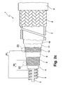
- a further metal sheath 15, 16 can be arranged adjacent to the outer metal sheath 7, the outside corresponding to FIG. 2b , ie between outer metal sheath 7 and braided hose 8, or according to FIG. 2c inside, ie between Isolierumhüllung 11 and outer metal sheath 7 is shown.
- This further metal envelope 15, 16 is formed without gaps, but nevertheless made flexible. It may be insulated from adjacent metallic layers by insulating sheaths.
- FIGS. 3a and 3b show various embodiments of the wire sheaths 5, 10.
- the wire sheath 5, 10 is formed by winding a single wire 12 (eg made of copper) and in FIG. 3b by winding a wire band 13 consisting of parallel wires 14 .
- the wire 12 and the wire band 13 are wound on the Isolierumhüllung 4 and 6, respectively, that results in a continuous layer of adjacent turns of wire.
- each wire sheath 5, 10 has two superimposed windings 5a, 5b and 10a, 10b with different winding direction. Compared to a wire mesh, this wire wrapping can completely be performed light-tight and thus forms a shield that prevents the escape of laser radiation from the laser light cable in case of damage.
Landscapes
- Physics & Mathematics (AREA)
- Engineering & Computer Science (AREA)
- Computer Security & Cryptography (AREA)
- General Physics & Mathematics (AREA)
- Optics & Photonics (AREA)
- Communication Cables (AREA)
- Insulated Conductors (AREA)
- Laser Surgery Devices (AREA)
- Removal Of Insulation Or Armoring From Wires Or Cables (AREA)
Abstract
Description
- Die vorliegende Erfindung betrifft ein Laserlichtkabel mit einem Lichtwellenleiter und einer diesen umgebenden Drahtumhüllung, die in Längsrichtung des Laserlichtkabels elektrisch leitend ist.
- Ein derartiges Laserlichtkabel ist beispielsweise durch die EP-A-1 378 778 bekannt geworden.
- Das aus EP-A-1 378 778 bekannte Laserlichtkabel weist zwischen einem inneren und einem äußeren Metallschutzschlauch eine Drahtumhüllung in Form eines metallischen Geflechtsschlauchs auf, der gegenüber den beiden Metallschutzschläuchen elektrisch isoliert ist. Der innere Metallschutzschlauch und der Geflechtsschlauch sind in einen elektrischen Sicherheitskreis zur Überwachung des Lichtwellenleiters eingebunden. Auf dem äußeren Metallschutzschlauch ist ein weiterer äußerer Geflechtsschlauch angeordnet, der einer Zug- und Druckbelastung des äußeren Metallschutzschlauchs entgegenwirkt. Der innere Metallschutzschlauch und der äußere Geflechtsschlauch sind in einen weiteren elektrischen Sicherheitskreis eingebunden. Im Schadensfall kann, beim Versagen beider Sicherheitskreise, aus dem Lichtwellenleiter austretende Laserstrahlung durch die als Metallwendel ausgebildeten Metallschutzschläuche und die Geflechtsschläuche hindurch nach außen dringen. Außerdem ist die Herstellung des Geflechtsschlauchs relativ aufwändig.
- Demgegenüber ist es die Aufgabe der vorliegenden Erfindung, ein Laserlichtkabel der eingangs genannten Art dahingehend weiterzubilden, dass die Drahtumhüllung einfacher hergestellt werden kann.
- Diese Aufgabe wird erfindungsgemäß dadurch gelöst, dass die Drahtumhüllung durch Wicklung eines einzelnen Drahts oder eines aus parallelen Drähten bestehenden Drahtbandes gebildet ist. Zumindest einige Drähte des Drahtbandes sind dabei elektrisch leitend, die übrigen Drähte können beispielsweise aus einem hochschmelzenden Kunststoff bestehen.
- Bei der erfindungsgemäßen Drahtumhüllung können axial benachbarte Drahtwindungen aneinander anliegend, d.h. ohne Zwischenraum, gefertigt werden, so dass die erfindungsgemäße Drahtumhüllung im Gegensatz zu einem Geflecht vollständig lichtdicht ausgeführt werden kann und eine Abschirmung der im Schadensfall aus dem Lichtwellenleiter austretenden Laserstrahlung erreicht wird. Für die optische Abschirmwirkung ist es vorteilhaft, wenn die Drahtwicklung vollständig metallisch ausgebildet ist.
- Besonders bevorzugt weist die Drahtumhüllung zwei Wicklungslagen mit gegenläufiger Wicklungsrichtung auf, wodurch die lichtdichte Abschirmung des Laserlichtkabels weiter verbessert wird.
- Weiterhin bevorzugt ist die Drahtumhüllung von einer in Längsrichtung des Laserlichtkabels elektrisch leitenden äußeren Drahtumhüllung umgeben, die ebenfalls durch Wicklung eines einzelnen Drahts oder eines aus parallelen Drähten bestehenden Drahtbandes gebildet ist. Vorteilhafterweise sind die beiden Drahtumhüllungen gegeneinander isoliert und jeweils in elektrische Sicherheitsschaltkreise eingebunden, durch die eine Beschädigung des Lichtwellenleiters und/oder einer einzelnen Komponente des Laserlichtkabels ermittelbar ist.
- Weitere vorteilhafte Ausgestaltungen der Erfindung sind Gegenstand der Unteransprüche.
- Weitere Vorteile der Erfindung ergeben sich aus der Beschreibung und der Zeichnung. Ebenso können die vorstehend genannten und die noch weiter aufgeführten Merkmale je für sich oder zu mehreren in beliebigen Kombinationen Verwendung finden. Die gezeigten und beschriebenen Ausführungsformen sind nicht als abschließende Aufzählung zu verstehen, sondern haben vielmehr beispielhaften Charakter für die Schilderung der Erfindung.
- Es zeigen:
- Fig. 1
- ein erstes Ausführungsbeispiel des erfindungsgemäßen Laserlichtkabels;
- Fig. 2a-2c
- verschiedene Varianten eines zweiten Ausführungsbeispiels des erfindungsgemäßen Laserlichtkabels;
- Fig. 3
- eine Detailansicht einer Drahtumhüllung, die aus einem einzelnen Draht (Fig. 3a) oder aus einem Drahtband (Fig. 3b) gewickelt ist, gemäß III in Fign. 1 und 2; und
- Fig. 4
- zwei Wickellagen einer Drahtumhüllung in einer Detailansicht analog zu Fig. 3.
- Das in Fig. 1 gezeigte Laserlichtkabel 1 ist von innen nach außen wie folgt aufgebaut:
- ein Lichtwellenleiter 2;
- eine innere Metallumhüllung 3 in Form einer Metallwendel;
- eine elektrisch nicht leitende Isolierumhüllung 4 aus z.B. Kunststoff (PVC);
- eine in Längsrichtung des Laserlichtkabels elektrisch leitende metallische Drahtumhüllung 5, deren Aufbau unten mit Bezug auf Fig. 3 beschrieben ist;
- eine elektrisch nicht leitende Isolierumhüllung 6 aus z.B. Kunststoff (PVC);
- eine äußere Metallumhüllung 7 in Form einer Flachband-Metallwendel;
- ein Geflechtsschlauch 8; und
- ein Außenmantel 9 aus Kunststoff.
- Die innere Metallumhüllung 3 und die äußere Metallumhüllung 7 sind in einen Ruhestromkreis (Sicherheitskreis S1) eingebunden. Wird infolge eines Schadens am Lichtwellenleiter 2 oder durch äußere Einflüsse die innere Metallumhüllung 3 zerstört, so wird der Stromfluss unterbrochen, und der Laser schaltet ab. Zwischen innerer Metallumhüllung 3 und Drahtumhüllung 5 wird zur Überwachung des Lichtwellenleiters 2 der Durchgangswiderstand durch die Isolierumhüllung 4 gemessen (Sicherheitskreis S2). Wird infolge eines Schadens am Lichtwellenleiter 2 die innere Metallumhüllung 3 und damit auch die Isolierumhüllung 4 heiß, so sinkt dieser Widerstand. Bei Unterschreitung eines Grenzwertes wird der Laser abgeschaltet. Außerdem kann die Kapazität zwischen innerer Metallumhüllung 3 und Drahtumhüllung 5 kontinuierlich überwacht werden.
- Die äußere Metallumhüllung 7 mit ihrem umflochtenen Geflechtsschlauch 8 und der umspritzte Außenmantel 9 dienen weiterhin zum mechanischen Schutz des Lichtwellenleiters 2 und zur Biegeradiusbegrenzung des Laserlichtkabels 1. Das Flachband der äußeren Metallumhüllung 7 besteht aus Edelstahl, der Geflechtsschlauch 8 ist mit Vorspannung auf die Flachbandwendel geflochten. Bei Zugbelastung des Laserlichtkabels 1 verhindert das Flachband eine Kontraktion des Geflechtsschlauchs 8 und stellt eine ausreichende Steifigkeit sicher. Bei Biegung des Laserlichtkabels 1 verhindert der Geflechtsschlauch 8, dass sich die Windungen des Flachbandes überlappen können. Hierdurch kann ein bestimmter Biegeradius nicht unterschritten werden.
- Von diesem Laserlichtkabel 1 unterscheidet sich das in Fig. 2a gezeigte Laserlichtkabel 1' durch eine zusätzliche (äußere, in Längsrichtung des Laserlichtkabels elektrisch leitende ) Drahtumhüllung 10, die zwischen der (inneren) Drahtumhüllung 5 und der äußeren Metallumhüllung 7 angeordnet und durch die lsolierumhüllungen 6, 11 elektrisch isoliert ist. In diesem Fall ist der Sicherheitskreis S1 zwischen innerer Metallumhüllung 3 und äußerer Drahtumhüllung 10 geschaltet. Da der Geflechtsschlauch 8 nicht in diesen Sicherheitskreis eingebunden ist, können der Geflechtsschlauch 8 und die äußere Metallumhüllung 7 als elektrische Abschirmung nach außen für die innere Metallumhüllung 3 und die Drahtumhüllungen 5, 10 genutzt werden. Dies vermindert die Störanfälligkeit der elektrischen Sicherheitskreise.
- Für eine Verbesserung der elektrischen Abschirmung nach außen kann benachbart zur äußeren Metallumhüllung 7 noch eine weitere Metallumhüllung 15, 16 angeordnet sein, die entsprechend Fig. 2b außen, d.h. zwischen äußerer Metallumhüllung 7 und Geflechtsschlauch 8, oder entsprechend Fig. 2c innen, d.h. zwischen Isolierumhüllung 11 und äußerer Metallumhüllung 7 gezeigt ist. Diese weitere Metallumhüllung 15, 16 ist lückenlos ausgebildet, aber trotzdem biegsam gestaltet. Sie kann gegenüber benachbarten metallischen Schichten durch Isolierumhüllungen isoliert sein.
- Fign. 3a und 3b zeigen verschiedene Ausführungsformen der Drahtumhüllungen 5, 10. In Fig. 3a ist die Drahtumhüllung 5, 10 durch Wicklung eines einzelnen Drahts 12 (z.B. aus Kupfer) und in Fig. 3b durch Wicklung eines aus parallelen Drähten 14 bestehenden Drahtbandes 13 gebildet. Der Draht 12 und das Drahtband 13 sind so auf die Isolierumhüllung 4 bzw. 6 gewickelt, dass sich eine durchgehende Schicht aus aneinander liegenden Drahtwindungen ergibt.
- Wie Fig. 4 zeigt, weist vorzugsweise jede Drahtumhüllung 5, 10 zwei übereinander liegende Wicklungen 5a, 5b bzw. 10a, 10b mit unterschiedlicher Wickelrichtung auf. lm Vergleich zu einem Drahtgeflecht kann diese Drahtumwicklung vollständig lichtdicht ausgeführt werden und bildet somit eine Abschirmung, die im Schadensfall den Austritt von Laserstrahlung aus dem Laserlichtkabel verhindert.
Claims (11)
- Laserlichtkabel (1; 1') mit einem Lichtwellenleiter (2) und einer diesen umgebenden, Drahtumhüllung (5), die in Längsrichtung des Laserlichtkabels (1, 1') elektrisch leitend ist,
dadurch gekennzeichnet,
dass die Drahtumhüllung (5) durch Wicklung eines einzelnen Drahts (12) oder eines aus parallelen Drähten (14) bestehenden Drahtbandes (13) gebildet ist. - Laserlichtkabel nach Anspruch 1, dadurch gekennzeichnet, dass die Drahtumhüllung (5) von einer in Längsrichtung des Laserlichtkabels elektrisch leitenden äußeren Drahtumhüllung (10) umgeben ist, die durch Wicklung eines einzelnen Drahts (12) oder eines aus parallelen Drähten (14) bestehenden Drahtbandes (13) gebildet ist.
- Laserlichtkabel nach Anspruch 2, dadurch gekennzeichnet, dass die beiden Drahtumhüllungen (5, 10) gegeneinander isoliert sind.
- Laserlichtkabel nach einem der vorhergehenden Ansprüche, dadurch gekennzeichnet, dass axial benachbarte Drahtwindungen der einen bzw. jeder Drahtumhüllung (5; 10) lichtdicht aneinander anliegen.
- Laserlichtkabel nach einem der vorhergehenden Ansprüche, dadurch gekennzeichnet, dass der einzelne Draht (12) bzw. einzelne oder alle Drähte (14) des Drahtbandes (13) der einen bzw. jeder Drahtumhüllung (5, 10) aus Metall, insbesondere aus Kupfer oder aus verkupfertem Stahl bestehen.
- Laserlichtkabel nach einem der vorhergehenden Ansprüche, dadurch gekennzeichnet, dass die eine bzw. jede Drahtumhüllung (5, 10) zwei Wicklungslagen (5a, 5b; 10a, 10b) mit gegenläufiger Wicklungsrichtung aufweist.
- Laserlichtkabel nach einem der vorhergehenden Ansprüche, dadurch gekennzeichnet, dass die eine bzw. die innere Drahtumhüllung (5, 10) eine den Lichtwellenleiter (2) umgebende innere Metallumhüllung (3) umgibt und dazwischen eine elektrische Isolierungsumhüllung (4) vorgesehen ist.
- Laserlichtkabel nach einem der vorhergehenden Ansprüche, dadurch gekennzeichnet, dass die eine bzw. die äußere Drahtumhüllung (5; 10) von einer äußeren Metallumhüllung (7) umgeben ist und dazwischen eine elektrische Isolierungsumhüllung (6) angeordnet ist.
- Laserlichtkabel nach Anspruch 7 oder 8, dadurch gekennzeichnet, dass zwischen innerer Metallumhüllung (3) und der einen bzw. der inneren Drahtumhüllung (5) ein elektrischer Sicherheitsschaltkreis (S2) geschaltet ist, durch den eine Beschädigung des Lichtwellenleiters (2) und/oder einer einzelnen Komponente des Laserlichtkabels (1; 1') ermittelbar ist.
- Laserlichtkabel nach einem der Ansprüche 7 bis 9, dadurch gekennzeichnet, dass zwischen innerer Metallumhüllung (3) und der äußeren Drahtumhüllung (10) oder der äußeren Metallumhüllung (7) ein elektrischer Sicherheitsschaltkreis (S1) geschaltet ist, durch den eine Beschädigung des Lichtwellenleiters (2) und/oder einer einzelnen Komponente des Laserlichtkabels (1; 1') ermittelbar ist.
- Laserlichtkabel nach einem der Ansprüche 8 bis 10, dadurch gekennzeichnet, dass benachbart zur äußeren Metallumhüllung (7) eine weitere, lückenlose Metallumhüllung (15, 16) angeordnet ist, die den bzw. die elektrischen Sicherheitsschaltkreise (S1, S2) nach außen elektrisch abschirmt und insbesondere gegen die äußere Metallumhüllung (7) elektrisch isoliert ist.
Priority Applications (4)
| Application Number | Priority Date | Filing Date | Title |
|---|---|---|---|
| DE502004000780T DE502004000780D1 (de) | 2004-09-18 | 2004-09-18 | Laserlichtkabel mit elektrisch leitender Drahtumhüllung |
| EP04022260A EP1637908B1 (de) | 2004-09-18 | 2004-09-18 | Laserlichtkabel mit elektrisch leitender Drahtumhüllung |
| AT04022260T ATE330242T1 (de) | 2004-09-18 | 2004-09-18 | Laserlichtkabel mit elektrisch leitender drahtumhüllung |
| US11/226,453 US7978944B2 (en) | 2004-09-18 | 2005-09-15 | Laser light cable |
Applications Claiming Priority (1)
| Application Number | Priority Date | Filing Date | Title |
|---|---|---|---|
| EP04022260A EP1637908B1 (de) | 2004-09-18 | 2004-09-18 | Laserlichtkabel mit elektrisch leitender Drahtumhüllung |
Publications (2)
| Publication Number | Publication Date |
|---|---|
| EP1637908A1 true EP1637908A1 (de) | 2006-03-22 |
| EP1637908B1 EP1637908B1 (de) | 2006-06-14 |
Family
ID=34926601
Family Applications (1)
| Application Number | Title | Priority Date | Filing Date |
|---|---|---|---|
| EP04022260A Expired - Lifetime EP1637908B1 (de) | 2004-09-18 | 2004-09-18 | Laserlichtkabel mit elektrisch leitender Drahtumhüllung |
Country Status (4)
| Country | Link |
|---|---|
| US (1) | US7978944B2 (de) |
| EP (1) | EP1637908B1 (de) |
| AT (1) | ATE330242T1 (de) |
| DE (1) | DE502004000780D1 (de) |
Families Citing this family (3)
| Publication number | Priority date | Publication date | Assignee | Title |
|---|---|---|---|---|
| US20090067776A1 (en) * | 2007-09-11 | 2009-03-12 | Schlumberger Technology Corporation | Optical fibers |
| DE102010026347B4 (de) | 2010-05-21 | 2025-12-04 | Günther Nath | Beleuchtungsvorrichtung mit Lichtleiter und Temperaturüberwachung |
| US20230194817A1 (en) * | 2021-12-21 | 2023-06-22 | Sterlite Technologies Limited | Optical fiber cable with coil elements |
Citations (4)
| Publication number | Priority date | Publication date | Assignee | Title |
|---|---|---|---|---|
| US4606604A (en) * | 1984-05-16 | 1986-08-19 | Optelecom, Inc. | Optical fiber submarine cable and method of making |
| EP0486136A1 (de) * | 1990-10-26 | 1992-05-20 | W.L. GORE & ASSOCIATES (UK) LTD | Flexible und druckfeste Leitungsführung |
| EP0516931A1 (de) * | 1991-06-03 | 1992-12-09 | Deutsche Aerospace Airbus Gesellschaft mit beschränkter Haftung | Leitung mit mindestens zwei separaten Übertragungskanälen |
| EP1378778A1 (de) * | 2002-07-03 | 2004-01-07 | Witzenmann GmbH | Schutzummantelung eines Glasfaserkabels für Laseranwendungen |
-
2004
- 2004-09-18 EP EP04022260A patent/EP1637908B1/de not_active Expired - Lifetime
- 2004-09-18 DE DE502004000780T patent/DE502004000780D1/de not_active Expired - Lifetime
- 2004-09-18 AT AT04022260T patent/ATE330242T1/de active
-
2005
- 2005-09-15 US US11/226,453 patent/US7978944B2/en not_active Expired - Fee Related
Patent Citations (4)
| Publication number | Priority date | Publication date | Assignee | Title |
|---|---|---|---|---|
| US4606604A (en) * | 1984-05-16 | 1986-08-19 | Optelecom, Inc. | Optical fiber submarine cable and method of making |
| EP0486136A1 (de) * | 1990-10-26 | 1992-05-20 | W.L. GORE & ASSOCIATES (UK) LTD | Flexible und druckfeste Leitungsführung |
| EP0516931A1 (de) * | 1991-06-03 | 1992-12-09 | Deutsche Aerospace Airbus Gesellschaft mit beschränkter Haftung | Leitung mit mindestens zwei separaten Übertragungskanälen |
| EP1378778A1 (de) * | 2002-07-03 | 2004-01-07 | Witzenmann GmbH | Schutzummantelung eines Glasfaserkabels für Laseranwendungen |
Also Published As
| Publication number | Publication date |
|---|---|
| ATE330242T1 (de) | 2006-07-15 |
| EP1637908B1 (de) | 2006-06-14 |
| US20060062530A1 (en) | 2006-03-23 |
| DE502004000780D1 (de) | 2006-07-27 |
| US7978944B2 (en) | 2011-07-12 |
Similar Documents
| Publication | Publication Date | Title |
|---|---|---|
| DE102005054926B4 (de) | Hochspannungs-Kabelbaum | |
| DE10245808B4 (de) | Verfahren zum Herstellen einer elektromagnetischen Abschirmungsstruktur und elektromagnetische Abschirmungsstruktur für elektrische Drähte | |
| DE102007023255B4 (de) | Abgeschirmter Draht | |
| EP1484945B1 (de) | Elektrische Heizleitung oder Heizband | |
| EP0619583B1 (de) | Elektrisches Rundkabel | |
| DE19706753A1 (de) | Kabel mit voneinander beabstandeten Wendeln | |
| WO2016082935A1 (de) | Kabel mit verseilten aderpaaren | |
| DE4236560A1 (de) | Kabel und Verfahren zur Herstellung eines Kabels | |
| CH643969A5 (de) | Supraleitender verbundleiter und verfahren zu dessen herstellung. | |
| DE112006003546T5 (de) | Koaxialkabel | |
| EP3147913B1 (de) | Konfektionierbares datenübertragungskabel | |
| DE69708040T2 (de) | Verbindungskabel | |
| EP1637908B1 (de) | Laserlichtkabel mit elektrisch leitender Drahtumhüllung | |
| DE69606519T2 (de) | Heizkabel mit variablem Leistungsbegrenzer | |
| EP4128286B1 (de) | Kabelschirmung | |
| DE10107429B4 (de) | Heizkabel mit Mehrschichtaufbau | |
| EP0397063A2 (de) | Einrichtung zum Schutz elektrischer Anlagen | |
| DE3233928A1 (de) | Flexibles elektrisches heiz- oder temperaturmesselement | |
| DE102014013558B4 (de) | Audiokabel zur Signalübertragung | |
| EP2581916A1 (de) | Zündkabel für hohe mechanische und/oder thermische Belastungen | |
| EP1378778B1 (de) | Schutzummantelung eines Glasfaserkabels für Laseranwendungen | |
| DE69412810T2 (de) | Elektrisches kabel und sein herstellungsverfahren | |
| EP1630825A2 (de) | Elektrische Leitung | |
| DE102016100143A1 (de) | Drahtanordnung für die Herstellung eines für einen Sicherheitszaun geeigneten Maschendrahtgeflechts, Maschendrahtgeflecht für einen Sicherheitszaun sowie Herstellungsverfahren | |
| EP0666576A2 (de) | Energiekabel |
Legal Events
| Date | Code | Title | Description |
|---|---|---|---|
| GRAP | Despatch of communication of intention to grant a patent |
Free format text: ORIGINAL CODE: EPIDOSNIGR1 |
|
| PUAI | Public reference made under article 153(3) epc to a published international application that has entered the european phase |
Free format text: ORIGINAL CODE: 0009012 |
|
| 17P | Request for examination filed |
Effective date: 20050831 |
|
| AK | Designated contracting states |
Kind code of ref document: A1 Designated state(s): AT BE BG CH CY CZ DE DK EE ES FI FR GB GR HU IE IT LI LU MC NL PL PT RO SE SI SK TR |
|
| GRAS | Grant fee paid |
Free format text: ORIGINAL CODE: EPIDOSNIGR3 |
|
| GRAA | (expected) grant |
Free format text: ORIGINAL CODE: 0009210 |
|
| AK | Designated contracting states |
Kind code of ref document: B1 Designated state(s): AT BE BG CH CY CZ DE DK EE ES FI FR GB GR HU IE IT LI LU MC NL PL PT RO SE SI SK TR |
|
| PG25 | Lapsed in a contracting state [announced via postgrant information from national office to epo] |
Ref country code: NL Free format text: LAPSE BECAUSE OF FAILURE TO SUBMIT A TRANSLATION OF THE DESCRIPTION OR TO PAY THE FEE WITHIN THE PRESCRIBED TIME-LIMIT Effective date: 20060614 Ref country code: PL Free format text: LAPSE BECAUSE OF FAILURE TO SUBMIT A TRANSLATION OF THE DESCRIPTION OR TO PAY THE FEE WITHIN THE PRESCRIBED TIME-LIMIT Effective date: 20060614 Ref country code: SI Free format text: LAPSE BECAUSE OF FAILURE TO SUBMIT A TRANSLATION OF THE DESCRIPTION OR TO PAY THE FEE WITHIN THE PRESCRIBED TIME-LIMIT Effective date: 20060614 Ref country code: SK Free format text: LAPSE BECAUSE OF FAILURE TO SUBMIT A TRANSLATION OF THE DESCRIPTION OR TO PAY THE FEE WITHIN THE PRESCRIBED TIME-LIMIT Effective date: 20060614 Ref country code: RO Free format text: LAPSE BECAUSE OF FAILURE TO SUBMIT A TRANSLATION OF THE DESCRIPTION OR TO PAY THE FEE WITHIN THE PRESCRIBED TIME-LIMIT Effective date: 20060614 Ref country code: CZ Free format text: LAPSE BECAUSE OF FAILURE TO SUBMIT A TRANSLATION OF THE DESCRIPTION OR TO PAY THE FEE WITHIN THE PRESCRIBED TIME-LIMIT Effective date: 20060614 Ref country code: IE Free format text: LAPSE BECAUSE OF FAILURE TO SUBMIT A TRANSLATION OF THE DESCRIPTION OR TO PAY THE FEE WITHIN THE PRESCRIBED TIME-LIMIT Effective date: 20060614 Ref country code: FI Free format text: LAPSE BECAUSE OF FAILURE TO SUBMIT A TRANSLATION OF THE DESCRIPTION OR TO PAY THE FEE WITHIN THE PRESCRIBED TIME-LIMIT Effective date: 20060614 |
|
| REG | Reference to a national code |
Ref country code: GB Ref legal event code: FG4D Free format text: NOT ENGLISH |
|
| REG | Reference to a national code |
Ref country code: CH Ref legal event code: EP |
|
| REG | Reference to a national code |
Ref country code: IE Ref legal event code: FG4D Free format text: LANGUAGE OF EP DOCUMENT: GERMAN |
|
| REF | Corresponds to: |
Ref document number: 502004000780 Country of ref document: DE Date of ref document: 20060727 Kind code of ref document: P |
|
| PG25 | Lapsed in a contracting state [announced via postgrant information from national office to epo] |
Ref country code: SE Free format text: LAPSE BECAUSE OF FAILURE TO SUBMIT A TRANSLATION OF THE DESCRIPTION OR TO PAY THE FEE WITHIN THE PRESCRIBED TIME-LIMIT Effective date: 20060914 Ref country code: DK Free format text: LAPSE BECAUSE OF FAILURE TO SUBMIT A TRANSLATION OF THE DESCRIPTION OR TO PAY THE FEE WITHIN THE PRESCRIBED TIME-LIMIT Effective date: 20060914 |
|
| PG25 | Lapsed in a contracting state [announced via postgrant information from national office to epo] |
Ref country code: ES Free format text: LAPSE BECAUSE OF FAILURE TO SUBMIT A TRANSLATION OF THE DESCRIPTION OR TO PAY THE FEE WITHIN THE PRESCRIBED TIME-LIMIT Effective date: 20060925 |
|
| PG25 | Lapsed in a contracting state [announced via postgrant information from national office to epo] |
Ref country code: MC Free format text: LAPSE BECAUSE OF NON-PAYMENT OF DUE FEES Effective date: 20060930 Ref country code: BE Free format text: LAPSE BECAUSE OF NON-PAYMENT OF DUE FEES Effective date: 20060930 |
|
| GBT | Gb: translation of ep patent filed (gb section 77(6)(a)/1977) |
Effective date: 20060921 |
|
| PG25 | Lapsed in a contracting state [announced via postgrant information from national office to epo] |
Ref country code: PT Free format text: LAPSE BECAUSE OF FAILURE TO SUBMIT A TRANSLATION OF THE DESCRIPTION OR TO PAY THE FEE WITHIN THE PRESCRIBED TIME-LIMIT Effective date: 20061114 |
|
| AKX | Designation fees paid |
Designated state(s): AT BE BG CH CY CZ DE DK EE ES FI FR GB GR HU IE IT LI LU MC NL PL PT RO SE SI SK TR |
|
| NLV1 | Nl: lapsed or annulled due to failure to fulfill the requirements of art. 29p and 29m of the patents act | ||
| REG | Reference to a national code |
Ref country code: IE Ref legal event code: FD4D |
|
| ET | Fr: translation filed | ||
| PLBE | No opposition filed within time limit |
Free format text: ORIGINAL CODE: 0009261 |
|
| STAA | Information on the status of an ep patent application or granted ep patent |
Free format text: STATUS: NO OPPOSITION FILED WITHIN TIME LIMIT |
|
| 26N | No opposition filed |
Effective date: 20070315 |
|
| BERE | Be: lapsed |
Owner name: TRUMPF LASER G.M.B.H. + CO. KG Effective date: 20060930 |
|
| PG25 | Lapsed in a contracting state [announced via postgrant information from national office to epo] |
Ref country code: GR Free format text: LAPSE BECAUSE OF FAILURE TO SUBMIT A TRANSLATION OF THE DESCRIPTION OR TO PAY THE FEE WITHIN THE PRESCRIBED TIME-LIMIT Effective date: 20060915 |
|
| PG25 | Lapsed in a contracting state [announced via postgrant information from national office to epo] |
Ref country code: BG Free format text: LAPSE BECAUSE OF FAILURE TO SUBMIT A TRANSLATION OF THE DESCRIPTION OR TO PAY THE FEE WITHIN THE PRESCRIBED TIME-LIMIT Effective date: 20060914 Ref country code: EE Free format text: LAPSE BECAUSE OF FAILURE TO SUBMIT A TRANSLATION OF THE DESCRIPTION OR TO PAY THE FEE WITHIN THE PRESCRIBED TIME-LIMIT Effective date: 20060614 |
|
| PG25 | Lapsed in a contracting state [announced via postgrant information from national office to epo] |
Ref country code: HU Free format text: LAPSE BECAUSE OF FAILURE TO SUBMIT A TRANSLATION OF THE DESCRIPTION OR TO PAY THE FEE WITHIN THE PRESCRIBED TIME-LIMIT Effective date: 20061215 Ref country code: LU Free format text: LAPSE BECAUSE OF NON-PAYMENT OF DUE FEES Effective date: 20060918 Ref country code: TR Free format text: LAPSE BECAUSE OF FAILURE TO SUBMIT A TRANSLATION OF THE DESCRIPTION OR TO PAY THE FEE WITHIN THE PRESCRIBED TIME-LIMIT Effective date: 20060614 |
|
| PG25 | Lapsed in a contracting state [announced via postgrant information from national office to epo] |
Ref country code: CY Free format text: LAPSE BECAUSE OF FAILURE TO SUBMIT A TRANSLATION OF THE DESCRIPTION OR TO PAY THE FEE WITHIN THE PRESCRIBED TIME-LIMIT Effective date: 20060614 |
|
| REG | Reference to a national code |
Ref country code: FR Ref legal event code: PLFP Year of fee payment: 13 |
|
| REG | Reference to a national code |
Ref country code: FR Ref legal event code: PLFP Year of fee payment: 14 |
|
| REG | Reference to a national code |
Ref country code: FR Ref legal event code: PLFP Year of fee payment: 15 |
|
| PGFP | Annual fee paid to national office [announced via postgrant information from national office to epo] |
Ref country code: FR Payment date: 20210921 Year of fee payment: 18 Ref country code: CH Payment date: 20210920 Year of fee payment: 18 Ref country code: AT Payment date: 20210921 Year of fee payment: 18 Ref country code: IT Payment date: 20210922 Year of fee payment: 18 |
|
| PGFP | Annual fee paid to national office [announced via postgrant information from national office to epo] |
Ref country code: DE Payment date: 20210920 Year of fee payment: 18 Ref country code: GB Payment date: 20210920 Year of fee payment: 18 |
|
| REG | Reference to a national code |
Ref country code: DE Ref legal event code: R119 Ref document number: 502004000780 Country of ref document: DE |
|
| REG | Reference to a national code |
Ref country code: CH Ref legal event code: PL |
|
| REG | Reference to a national code |
Ref country code: AT Ref legal event code: MM01 Ref document number: 330242 Country of ref document: AT Kind code of ref document: T Effective date: 20220918 |
|
| GBPC | Gb: european patent ceased through non-payment of renewal fee |
Effective date: 20220918 |
|
| PG25 | Lapsed in a contracting state [announced via postgrant information from national office to epo] |
Ref country code: LI Free format text: LAPSE BECAUSE OF NON-PAYMENT OF DUE FEES Effective date: 20220930 Ref country code: FR Free format text: LAPSE BECAUSE OF NON-PAYMENT OF DUE FEES Effective date: 20220930 Ref country code: DE Free format text: LAPSE BECAUSE OF NON-PAYMENT OF DUE FEES Effective date: 20230401 Ref country code: CH Free format text: LAPSE BECAUSE OF NON-PAYMENT OF DUE FEES Effective date: 20220930 Ref country code: AT Free format text: LAPSE BECAUSE OF NON-PAYMENT OF DUE FEES Effective date: 20220918 |
|
| PG25 | Lapsed in a contracting state [announced via postgrant information from national office to epo] |
Ref country code: IT Free format text: LAPSE BECAUSE OF NON-PAYMENT OF DUE FEES Effective date: 20220918 Ref country code: GB Free format text: LAPSE BECAUSE OF NON-PAYMENT OF DUE FEES Effective date: 20220918 |