EP1637750A1 - Rückhaltesystem für ein Befestigungsmittel - Google Patents
Rückhaltesystem für ein Befestigungsmittel Download PDFInfo
- Publication number
- EP1637750A1 EP1637750A1 EP05017888A EP05017888A EP1637750A1 EP 1637750 A1 EP1637750 A1 EP 1637750A1 EP 05017888 A EP05017888 A EP 05017888A EP 05017888 A EP05017888 A EP 05017888A EP 1637750 A1 EP1637750 A1 EP 1637750A1
- Authority
- EP
- European Patent Office
- Prior art keywords
- hole
- projections
- restraint system
- thread
- fastening means
- Prior art date
- Legal status (The legal status is an assumption and is not a legal conclusion. Google has not performed a legal analysis and makes no representation as to the accuracy of the status listed.)
- Granted
Links
- 230000014759 maintenance of location Effects 0.000 title description 4
- 238000003780 insertion Methods 0.000 claims description 4
- 230000037431 insertion Effects 0.000 claims description 4
- 238000005516 engineering process Methods 0.000 description 3
- 238000004519 manufacturing process Methods 0.000 description 3
- 238000009434 installation Methods 0.000 description 2
- 229920003023 plastic Polymers 0.000 description 2
- 239000004033 plastic Substances 0.000 description 2
- 230000015572 biosynthetic process Effects 0.000 description 1
- 230000001419 dependent effect Effects 0.000 description 1
- 229910052736 halogen Inorganic materials 0.000 description 1
- 150000002367 halogens Chemical class 0.000 description 1
- 238000001746 injection moulding Methods 0.000 description 1
- 238000003825 pressing Methods 0.000 description 1
- 238000010079 rubber tapping Methods 0.000 description 1
- 239000007779 soft material Substances 0.000 description 1
- 239000000243 solution Substances 0.000 description 1
Images
Classifications
-
- F—MECHANICAL ENGINEERING; LIGHTING; HEATING; WEAPONS; BLASTING
- F16—ENGINEERING ELEMENTS AND UNITS; GENERAL MEASURES FOR PRODUCING AND MAINTAINING EFFECTIVE FUNCTIONING OF MACHINES OR INSTALLATIONS; THERMAL INSULATION IN GENERAL
- F16B—DEVICES FOR FASTENING OR SECURING CONSTRUCTIONAL ELEMENTS OR MACHINE PARTS TOGETHER, e.g. NAILS, BOLTS, CIRCLIPS, CLAMPS, CLIPS OR WEDGES; JOINTS OR JOINTING
- F16B41/00—Measures against loss of bolts, nuts, or pins; Measures against unauthorised operation of bolts, nuts or pins
- F16B41/002—Measures against loss of bolts, nuts or pins
-
- F—MECHANICAL ENGINEERING; LIGHTING; HEATING; WEAPONS; BLASTING
- F16—ENGINEERING ELEMENTS AND UNITS; GENERAL MEASURES FOR PRODUCING AND MAINTAINING EFFECTIVE FUNCTIONING OF MACHINES OR INSTALLATIONS; THERMAL INSULATION IN GENERAL
- F16B—DEVICES FOR FASTENING OR SECURING CONSTRUCTIONAL ELEMENTS OR MACHINE PARTS TOGETHER, e.g. NAILS, BOLTS, CIRCLIPS, CLAMPS, CLIPS OR WEDGES; JOINTS OR JOINTING
- F16B5/00—Joining sheets or plates, e.g. panels, to one another or to strips or bars parallel to them
- F16B5/02—Joining sheets or plates, e.g. panels, to one another or to strips or bars parallel to them by means of fastening members using screw-thread
- F16B5/0208—Joining sheets or plates, e.g. panels, to one another or to strips or bars parallel to them by means of fastening members using screw-thread using panel fasteners, i.e. permanent attachments allowing for quick assembly
Definitions
- the invention relates to a retention system for threaded fasteners according to the preamble of patent claim 1.
- a disadvantage of such restraint systems is that due to the pitch of the longitudinal axis of the fastener does not match the longitudinal axis of the through hole - in other words - the fastener takes in the preassembled position a "crooked" position in the through hole and can not properly in the further assembly a second component to be screwed.
- a restraint system in which a single thread is formed in a through-hole in order to hold a fastening screw perpendicular to the longitudinal axis of the through-hole. It has been found that although the longitudinal axis of the fastener coincides with the longitudinal axis of the through-hole due to the thread formation in the through-hole, the actually loose connection can become a firm connection when the screw is self-tapping in the thread of the through-hole, rather than the two Connect components together.
- the invention has for its object to provide a restraint system for fastening means, in particular for fastening screws, which allows over conventional solutions improved mounting of the fastener in a through hole.
- the retention system has at least two substantially diametrically arranged in a through hole of a component projections, which are offset in the axial direction as a function of the thread pitch of a fastener to each other.
- fastening means all threaded fasteners, in particular screws or bolts can be used.
- the side surfaces of the projections are at least partially engageable with thread flanks of the fastener.
- the restraint system is thereby able to prevent the fastener from falling out and to keep the longitudinal axis of the fastener in a position corresponding approximately to the longitudinal axis of the through-hole. As a result, tilting of the fastening means in the through hole is effectively prevented and substantially facilitates further assembly.
- two projections are arranged offset in the through hole as seen in the axial direction by an amount which corresponds approximately to half the pitch of the thread pitch of a fastener or an odd multiple thereof.
- the projections are transversely to the axial direction arranged at a distance from each other, which is slightly larger than the core diameter, but smaller than the outer thread diameter of the fastening means. This ensures that the fastening means within the Through hole remains movably arranged, but is held captive in the through hole due to the smaller distance between the projections relative to the larger thread outer diameter of the fastening means.
- the projections may be formed elastically deformable, so that an insertion of the fastening means in the through hole in the axial direction is possible - in other words - in the restraint system according to the invention, the fastening means can be pressed axially into the through hole, wherein the projections deform elastically, in the Thread profile penetrate and thereby hold the fastener in the through hole.
- edges of the projections are arranged parallel to each other and tangential to the through hole.
- the edges allow a symmetrical recording of the fastener in the through hole.
- the projections are preferably arranged on the two longer sides of the slot. This design of the restraint system allows a tolerance compensation of the inevitable existing manufacturing tolerances to be connected components during assembly, since the fastening means is slidably received along a longitudinal axis of the elongated hole.
- the component is preferably a cable cover for a transformer for operating a lamp.
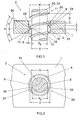
- FIG. 1 shows a sectional view through a component 1, for example a cable cover of an electronic transformer HTM 70 or HTM 105, with a retaining system 2 according to the invention for threaded fasteners.
- the restraint system 2 has two diametrically arranged in a through hole 4 of the component 1 projections 6, 8, viewed in the axial direction depending on the pitch P of a fixing screw used as fastening means 10 are offset from one another.
- the two projections 6, 8 are arranged in the axial direction by an amount Y, which corresponds approximately to half the pitch of the thread pitch P, offset in the through hole 4.
- the projections 6, 8 In the radial direction with respect to the fastening screw 10, the projections 6, 8 at a distance X arranged to each other, which is slightly larger than a core diameter d k but smaller than a thread outer diameter d of a thread 11 of the fastening screw 10 (see also Figure 2). This ensures that the fastening screw 10 is held captive in the through hole 4 due to the smaller distance between the projections 6, 8 relative to the larger outer diameter d of the screw thread 10.
- the projections 6, 8 are formed integrally and with an approximately wedge-shaped cross section on the first component 1, wherein side surfaces 12, 14 of the projections 6, 8 with thread flanks 16, 18 of the fastening screw 10 at least partially can be brought into abutment.
- the restraint system 2 is able to prevent the fastening screw 10 from falling out and to hold a longitudinal axis 20 of the fastening screw 10 in a position which corresponds approximately to a longitudinal axis 22 of the through-hole 4. Tilting of the fastening screw 10 in the through hole 4 is thereby prevented and facilitates the assembly much.
- the projections 6, 8 may be formed elastically deformable to allow an axial insertion of the fastening screw 10 in the through hole 4. Thereby, the fastening screw 10 can be pressed axially into the through hole 4, wherein the projections 6, 8 elastically deform, penetrate into a thread profile 24 and thereby hold the fastening screw 10 in the through hole 4.
- Each of the two wedge-shaped projections 6, 8 has two side surfaces 12, 14 which enclose a vertex angle ⁇ formed by an angle ⁇ and an angle ⁇ and form a common edge 26, 28.
- the angles ⁇ and ⁇ may be formed symmetrically or asymmetrically to a vertex axis 30, 32 of the projections 6, 8 and are preferably between 10 ° and 45 °.
- the angle ⁇ facing the fastening means 10 during pre-assembly can be made larger in relation to the angle ⁇ and serve as an insertion aid.
- the angles ⁇ and ⁇ are in the embodiment shown about 30 ° and are therefore formed symmetrically to the apex axis 30, 32.
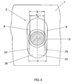
- FIG. 3 shows a plan view of a restraint system 2 formed in a slot 38, wherein the sectional side view corresponds to the representation of the exemplary embodiment in FIG.
- the projections 6, 8 are arranged diametrically on the two longer sides of the slot 38.
- This embodiment of the restraint system 2 allows compensation of manufacturing tolerances during assembly, since the fastening screw 10 is slidably received along a longitudinal axis 40 of the elongated hole 38 and thereby guided by the projections 6, 8.
Landscapes
- Engineering & Computer Science (AREA)
- General Engineering & Computer Science (AREA)
- Mechanical Engineering (AREA)
- Connection Of Plates (AREA)
- Clamps And Clips (AREA)
- Hooks, Suction Cups, And Attachment By Adhesive Means (AREA)
- Slide Fasteners, Snap Fasteners, And Hook Fasteners (AREA)
- Dowels (AREA)
Abstract
Description
- Die Erfindung betrifft ein Rückhaltesystem für mit einem Gewinde versehene Befestigungsmittel gemäß dem Oberbegriff des Patentanspruchs 1.
- Zur Steigerung der Wirtschaftlichkeit moderner Fertigungsabläufe werden Einzelbauteile häufig vom Hersteller vormontiert an den Montageort geliefert. Dabei sind die Bauelemente bereits mit den zur weiteren Montage erforderlichen Befestigungsmitteln wie beispielsweise Schrauben oder Bolzen ausgestattet, d.h. die Befestigungsmittel sind montagebereit, jedoch lose in einem der Bauelemente eingesetzt. Insbesondere in der Gehäusetechnik, beispielsweise bei elektronischen Transformatoren der Niedervolt-Halogenlichttechnik, werden bereits anschlussfertig vormontierte Einheiten verwendet, bei denen die zum Anschluss der Leitungen vorbereiteten Klemmleisten von einem mit einer Befestigungsschraube versehenen Gehäusedeckel verschließbar sind. Dadurch wird ein kompaktes und zugleich montagefreundliches Design erreicht und der Installationsaufwand auf ein Minimum reduziert.
- Während dem Transport und vor der Montage bzw. nach der Demontage der Bauelemente besteht jedoch die Gefahr, dass sich Befestigungsmittel aus den Durchgangslöchern lösen und verloren gehen. Um dies zu verhindern, wurden Rückhaltesysteme entwickelt, die durch Formschluss zwischen dem Gewinde des Befestigungsmittels und dem Bauelement einen sicheren Verlierschutz bieten.
- Zur Verliersicherung von Befestigungsmitteln in einem Durchgangsloch ist es aus dem allgemeinen Stand der Technik bekannt, einen ringförmigen Vorsprung innerhalb des Durchgangslochs vorzusehen, dessen Innendurchmesser etwas kleiner gewählt ist als der Gewindeaußendurchmesser des Befestigungsmittels. Bei einem derartigen Rückhaltesystem wird das Befestigungsmittel axial in das Durchgangsloch eingedrückt, wobei sich der ringförmige Vorsprung elastisch verformt, in das Gewindeprofil eindringt und dadurch die Befestigungsschraube in dem Durchgangsloch sichert. Nachteilig bei derartigen Rückhaltesystemen ist, dass aufgrund der Gewindesteigung die Längsachse des Befestigungselements nicht mit der Längsachse des Durchgangslochs übereinstimmt - mit anderen Worten - das Befestigungsmittel nimmt in der vormontierten Position eine "schiefe" Lage im Durchgangsloch ein und kann bei der weiteren Montage nicht ordnungsgemäß in ein zweites Bauelement eingeschraubt werden.
- Auch durch eine unterbrochene Ausgestaltung des ringförmigen Vorsprungs konnte die genannte Problematik der "schiefen Schraube" aufgrund des Gewindeeingriffs in die nunmehr vorhandenen Unterbrechungen nicht verbessert werden.
- Weiterhin ist aus dem allgemeinen Stand der Technik ein Rückhaltesystem bekannt, bei dem in einem Durchgangsloch ein einzelner Gewindegang ausgebildet ist, um eine Befestigungsschraube senkrecht zur Längsachse des Durchgangslochs zu halten. Es zeigte sich, dass aufgrund der Gewindeausbildung in dem Durchgangsloch zwar die Längsachse des Befestigungselements mit der Längsachse des Durchgangslochs übereinstimmt, dass aber die eigentlich lose Verbindung zu einer festen Verbindung werden kann, wenn die Schraube sich im Gewindegang des Durchgangslochs selbst festschraubt, anstatt die beiden Bauelemente miteinander zu verbinden.
- Der Erfindung liegt die Aufgabe zugrunde, ein Rückhaltesystem für Befestigungsmittel, insbesondere für Befestigungsschrauben zu schaffen, das gegenüber herkömmlichen Lösungen eine verbesserte Halterung des Befestigungsmittels in einem Durchgangsloch ermöglicht.
- Diese Aufgabe wird erfindungsgemäß durch die Merkmale des Patentanspruchs 1 gelöst. Besonders vorteilhafte Ausführungen der Erfindung sind in den abhängigen Ansprüchen beschrieben.
- Das erfindungsgemäße Rückhaltesystem hat zumindest zwei im Wesentlichen diametral in einem Durchgangsloch eines Bauelements angeordnete Vorsprünge, die in Axialrichtung gesehen in Abhängigkeit von der Gewindesteigung eines Befestigungsmittels zueinander versetzt sind. Als Befestigungsmittel können alle mit einem Gewinde versehenen Befestigungsmittel, insbesondere Schrauben oder Bolzen Verwendung finden. Die Seitenflächen der Vorsprünge sind mit Gewindeflanken des Befestigungsmittels zumindest abschnittsweise in Anlage bringbar. Das Rückhaltesystem ist dadurch in der Lage, das Befestigungsmittel am Herausfallen zu hindern und die Längsachse des Befestigungsmittels in einer Position zu halten, die in etwa der Längsachse des Durchgangslochs entspricht. Dadurch wird ein Verkanten des Befestigungsmittels im Durchgangsloch wirkungsvoll verhindert und die weitere Montage wesentlich erleichtert.
- Gemäß einem besonders bevorzugten Ausführungsbeispiel sind zwei Vorsprünge in Axialrichtung gesehen um einen Betrag, der in etwa dem halben Abstand der Gewindesteigung eines Befestigungsmittels oder einem ungeradzahligen Vielfachen davon entspricht, versetzt in dem Durchgangsloch angeordnet.
- Vorzugsweise sind die Vorsprünge quer zur Axialrichtung gesehen in einem Abstand zueinander angeordnet, der etwas größer als der Kerndurchmesser, aber kleiner als der Gewindeaußendurchmesser des Befestigungsmittels ist. Hierdurch wird erreicht, dass das Befestigungsmittel innerhalb des Durchgangslochs beweglich angeordnet bleibt, jedoch aufgrund des kleineren Abstands zwischen den Vorsprüngen gegenüber dem größeren Gewindeaußendurchmesser des Befestigungsmittels unverlierbar in dem Durchgangsloch gehalten ist.
- Als besonders vorteilhaft hat es sich erwiesen, die Vorsprünge einstückig mit der Durchgangsbohrung bspw. in Kunststoff-Spritzgusstechnik als Kreissegmente mit einem etwa keilförmigen Querschnitt auszubilden.
- Die Vorsprünge können elastisch verformbar ausgebildet werden, so dass ein Einführen des Befestigungsmittels in das Durchgangsloch in axialer Richtung ermöglicht ist - mit anderen Worten - bei dem erfindungsgemäßen Rückhaltesystem kann das Befestigungsmittel axial in das Durchgangsloch eingedrückt werden, wobei sich die Vorsprünge elastisch verformen, in das Gewindeprofil eindringen und dadurch das Befestigungsmittel in der Durchgangsbohrung halten. Bei dieser Variante wird zum Einen aufgrund der elastisch ausgebildeten Vorsprünge ein Hindurchdrücken des Befestigungsmittels durch das in einem ersten Bauelement ausgebildete Durchgangsloch und zum Anderen das Ein- und Festschrauben des Befestigungsmittels direkt in dem zweiten Bauelement - bei weichen Werkstoffen, insbesondere bei Kunststoffen werden häufig Schrauben verwendet, die ihr Muttergewinde beim Einschrauben selbsttätig in das zweite Bauelement schneiden - oder einer Schraubenmutter, ohne ein ungewolltes Festgehen im Durchgangsloch ermöglicht. Dadurch ist ein Verbinden der beiden Bauelemente spaltfrei möglich und das Befestigungsmittel vor der Montage bzw. nach der Demontage gegen Verlieren gesichert.
- Bei einer bevorzugten Ausbildung der Erfindung sind Kanten der Vorsprünge parallel zueinander und tangential zum Durchgangsloch angeordnet. Die Kanten ermöglichen eine symmetrische Aufnahme des Befestigungsmittels in dem Durchgangsloch.
- Handelt es sich bei dem Durchgangsloch um ein Langloch, so sind die Vorsprünge vorzugsweise an den beiden längeren Seiten des Langlochs angeordnet. Diese Ausführung des Rückhaltesystems ermöglicht einen Toleranzausgleich der zwangsläufig vorhandenen Fertigungstoleranzen der zu verbindenden Bauelemente bei der Montage, da das Befestigungsmittel entlang einer Längsachse des Langlochs verschiebbar aufgenommen ist.
- Das Bauelement ist vorzugsweise eine Kabelabdeckung für einen Transformator zum Betrieb einer Lampe.
- Nachstehend wird die Erfindung anhand bevorzugter Ausführungsbeispiele näher erläutert. Es zeigen:
- Figur 1
- eine Schnittdarstellung durch ein Bauelement mit einem erfindungsgemäßen Rückhaltesystem;
- Figur 2
- eine Draufsicht auf das Rückhaltesystem aus Figur 1 und
- Figur 3
- eine Draufsicht auf ein in einem Langloch ausgebildetes Rückhaltesystem.
- Figur 1 zeigt eine Schnittdarstellung durch ein Bauelement 1, bspw. eine Kabelabdeckung eines elektronischen Trafos HTM 70 bzw. HTM 105, mit einem erfindungsgemäßen Rückhaltesystem 2 für mit einem Gewinde versehene Befestigungsmittel. Das Rückhaltesystem 2 weist zwei diametral in einem Durchgangsloch 4 des Bauelements 1 angeordnete Vorsprünge 6, 8 auf, die in Axialrichtung gesehen in Abhängigkeit von der Gewindesteigung P einer als Befestigungsmittel verwendeten Befestigungsschraube 10 zueinander versetzt sind.
- Die beiden Vorsprünge 6, 8 sind in Axialrichtung um einen Betrag Y, der in etwa dem halben Abstand der Gewindesteigung P entspricht, versetzt in dem Durchgangsloch 4 angeordnet. In Radialrichtung mit Bezug zur Befestigungsschraube 10 sind die Vorsprünge 6, 8 in einem Abstand X zueinander angeordnet, der etwas größer als ein Kerndurchmesser dk aber kleiner als ein Gewindeaußendurchmesser d eines Gewindes 11 der Befestigungsschraube 10 ist (siehe auch Figur 2). Hierdurch wird erreicht, dass die Befestigungsschraube 10 aufgrund des kleineren Abstands zwischen den Vorsprüngen 6, 8 gegenüber dem größeren Gewindeaußendurchmesser d der Befestigungsschraube 10 unverlierbar in dem Durchgangsloch 4 gehalten ist.
- Die Vorsprünge 6, 8 sind einstückig und mit einem etwa keilförmigen Querschnitt an dem ersten Bauelement 1 ausgebildet, wobei Seitenflächen 12, 14 der Vorsprünge 6, 8 mit Gewindeflanken 16, 18 der Befestigungsschraube 10 zumindest abschnittsweise in Anlage bringbar sind. Dadurch ist das Rückhaltesystem 2 in der Lage, die Befestigungsschraube 10 am Herausfallen zu hindern und eine Längsachse 20 der Befestigungsschraube 10 in einer Position zu halten, die in etwa einer Längsachse 22 des Durchgangslochs 4 entspricht. Ein Verkanten der Befestigungsschraube 10 im Durchgangsloch 4 wird dadurch verhindert und die Montage wesentlich erleichtert.
- Weiterhin können die Vorsprünge 6, 8 elastisch verformbar ausgebildet sein, um ein axiales Einführen der Befestigungsschraube 10 in das Durchgangsloch 4 zu ermöglichen. Dadurch kann die Befestigungsschraube 10 axial in das Durchgangsloch 4 eingedrückt werden, wobei sich die Vorsprünge 6, 8 elastisch verformen, in ein Gewindeprofil 24 eindringen und dadurch die Befestigungsschraube 10 in dem Durchgangsloch 4 halten.
- Jeder der beiden keilförmigen Vorsprünge 6, 8 hat zwei Seitenflächen 12, 14, die einen von einem Winkel β und einem Winkel δ gebildeten Scheitelwinkel α einschließen und eine gemeinsame Kante 26, 28 ausbilden. Die Winkel β bzw. δ können symmetrisch oder asymmetrisch zu einer Scheitelachse 30, 32 der Vorsprünge 6, 8 ausgebildet sein und betragen vorzugsweise zwischen 10° und 45°. Insbesondere kann der dem Befestigungsmittel 10 bei der Vormontage zugewandte Winkel β im Verhältnis zu dem Winkel δ größer ausgeführt sein und als Einführhilfe dienen. Die Winkel β bzw. δ betragen bei dem gezeigten Ausführungsbeispiel etwa 30° und sind demnach symmetrisch zu der Scheitelachse 30, 32 ausgebildet.
- Gemäß Figur 2 sind die beiden diametral angeordneten Vorsprünge 6, 8 als in das Durchgangsloch 4 radial vorstehende Kreissegmente 34, 36 ausgeführt, wobei die Kanten 26, 28 der Vorsprünge 6, 8 in der Ansicht nach Figur 2 parallel zueinander und tangential zum Durchgangsloch 4 angeordnet sind.
- Figur 3 zeigt eine Draufsicht auf ein in einem Langloch 38 ausgebildetes Rückhaltesystem 2, wobei die geschnittene Seitenansicht der Darstellung des Ausführungsbeispiels in Figur 1 entspricht. Bei dem in Figur 3 dargestellten Ausführungsbeispiel sind die Vorsprünge 6, 8 diametral an den beiden längeren Seiten des Langlochs 38 angeordnet. Diese Ausführung des Rückhaltesystems 2 ermöglicht einen Ausgleich der Fertigungstoleranzen bei der Montage, da die Befestigungsschraube 10 entlang einer Längsachse 40 des Langlochs 38 verschiebbar aufgenommen ist und dabei von den Vorsprüngen 6, 8 geführt ist.
- Offenbart ist ein Rückhaltesystem 2 für mit einem Gewinde 11 versehene Befestigungsmittel 10, insbesondere für Befestigungsschrauben in einem Durchgangsloch 4 eines Bauelements 1, wobei zumindest zwei im Wesentlichen diametral ausgebildete Vorsprünge 6, 8 in dem Durchgangsloch 4 angeordnet sind, die in Axialrichtung gesehen in Abhängigkeit von einer Gewindesteigung P des Befestigungsmittels 10 zueinander versetzt sind.
-
- 1
- Bauelement
- 2
- Rückhaltesystem
- 4
- Durchgangsloch
- 6
- Vorsprung
- 8
- Vorsprung
- 10
- Befestigungsmittel
- 11
- Gewinde
- 12
- Seitenfläche
- 14
- Seitenfläche
- 16
- Gewindeflanke
- 18
- Gewindeflanke
- 20
- Längsachse Befestigungsschraube
- 22
- Längsachse Durchgangsloch
- 24
- Gewindeprofil
- 26
- Kante
- 28
- Kante
- 30
- Scheitelachse
- 32
- Scheitelachse
- 34
- Kreissegment
- 36
- Kreissegment
- 38
- Langloch
- 40
- Längsachse Langloch
Claims (8)
- Rückhaltesystem (2) für mit einem Gewinde (11) versehene Befestigungsmittel (10), insbesondere für Befestigungsschrauben in einem Durchgangsloch (4) eines Bauelements (1), dadurch gekennzeichnet, dass zumindest zwei im Wesentlichen diametral ausgebildete Vorsprünge (6, 8) in dem Durchgangsloch (4) angeordnet sind, die in Axialrichtung in Abhängigkeit von einer Gewindesteigung (P) des Befestigungsmittels (10) zueinander versetzt sind.
- Rückhaltesystem nach Anspruch 1, wobei die zwei Vorsprünge (6, 8) in Axialrichtung um einen Betrag (Y), der dem halben Abstand der Gewindesteigung (P) oder einem ungeradzahligen Vielfachen davon entspricht, versetzt in dem Durchgangsloch (4) angeordnet sind.
- Rückhaltesystem nach Anspruch 1 oder 2, wobei die Vorsprünge (6, 8) in Radialrichtung in einem Abstand (X) zueinander angeordnet sind, der größer als ein Kerndurchmesser (dk) aber kleiner als ein Gewindeaußendurchmesser (d) des Befestigungsmittels (10) ist.
- Rückhaltesystem nach einem der vorhergehenden Ansprüche, wobei die Vorsprünge (6, 8) elastisch verformbar ausgebildet sind, so dass ein Einführen des Befestigungsmittels (10) in das Durchgangsloch (4) in axialer Richtung ermöglicht ist.
- Rückhaltesystem nach einem der vorhergehenden Ansprüche, wobei die Vorsprünge (6, 8) als Kreissegmente (34, 36) ausgebildet sind und vorzugsweise einen etwa keilförmigen Querschnitt aufweisen.
- Rückhaltesystem nach Anspruch 5, wobei radial innenliegende Kanten (26, 28) der Vorsprünge (6, 8) parallel zueinander angeordnet sind.
- Rückhaltesystem nach einem der vorhergehenden Ansprüche, wobei das Durchgangsloch (4) ein Langloch (38) ist und die Vorsprünge (6, 8) an den beiden längeren Seiten des Langlochs (38) angeordnet sind.
- Rückhaltesystem nach einem der vorhergehenden Ansprüche, wobei das Bauelement (1) eine Kabelabdeckung für einen Transformator zum Betrieb einer Lampe ist.
Applications Claiming Priority (1)
| Application Number | Priority Date | Filing Date | Title |
|---|---|---|---|
| DE102004044684A DE102004044684A1 (de) | 2004-09-15 | 2004-09-15 | Rückhaltesystem für ein Befestigungsmittel |
Publications (2)
| Publication Number | Publication Date |
|---|---|
| EP1637750A1 true EP1637750A1 (de) | 2006-03-22 |
| EP1637750B1 EP1637750B1 (de) | 2007-05-02 |
Family
ID=35431127
Family Applications (1)
| Application Number | Title | Priority Date | Filing Date |
|---|---|---|---|
| EP05017888A Expired - Lifetime EP1637750B1 (de) | 2004-09-15 | 2005-08-17 | Rückhaltesystem für ein Befestigungsmittel |
Country Status (6)
| Country | Link |
|---|---|
| EP (1) | EP1637750B1 (de) |
| CN (1) | CN100441889C (de) |
| AT (1) | ATE361433T1 (de) |
| AU (1) | AU2005211524B2 (de) |
| DE (2) | DE102004044684A1 (de) |
| TW (1) | TW200613650A (de) |
Cited By (2)
| Publication number | Priority date | Publication date | Assignee | Title |
|---|---|---|---|---|
| ITTO20110719A1 (it) * | 2011-08-02 | 2013-02-03 | Eldor Corp Spa | Dispositivo di fissaggio a vite imperdibile e procedimento per la sua realizzazione |
| FR3068743A1 (fr) * | 2017-07-10 | 2019-01-11 | Psa Automobiles Sa | Dispositif anti-vibration a entretoise a fonction de pre-maintien, pour un dispositif fonctionnel |
Families Citing this family (5)
| Publication number | Priority date | Publication date | Assignee | Title |
|---|---|---|---|---|
| DE102017107162A1 (de) * | 2017-04-04 | 2018-10-04 | Eberspächer Exhaust Technology GmbH & Co. KG | Montagebaugruppe |
| DE102018114104A1 (de) * | 2017-06-22 | 2018-12-27 | Schaeffler Technologies AG & Co. KG | Schwungmassenanordnung mit Verschraubung und Verfahren zur Herstellung dieser |
| WO2023139511A1 (de) * | 2022-01-21 | 2023-07-27 | Adient Us Llc | Befestigungsvorrichtung zum verbinden eines schienenelements mit einem strukturelement eines fahrzeugs und schienenelement |
| CN114962426B (zh) * | 2022-05-18 | 2023-09-26 | 中航沈飞民用飞机有限责任公司 | 一种于斜面上保证螺栓与结构孔同轴度的装置 |
| CN115355233B (zh) * | 2022-07-15 | 2026-01-02 | 中国电子科技集团公司第十一研究所 | 一种不松脱的紧固组件、光电系统及光电系统的紧固方法 |
Citations (2)
| Publication number | Priority date | Publication date | Assignee | Title |
|---|---|---|---|---|
| US5489177A (en) * | 1994-06-08 | 1996-02-06 | Crest Products, Inc. | Fastener assembly with axially captivated washer |
| EP0751305A1 (de) * | 1995-06-26 | 1997-01-02 | Valeo Systemes D'essuyage | Anordnung zur Befestigung eines Elementes von einem Scheibenwischer an einer Kraftfahrzeugkarrosserie |
-
2004
- 2004-09-15 DE DE102004044684A patent/DE102004044684A1/de not_active Withdrawn
-
2005
- 2005-08-17 AT AT05017888T patent/ATE361433T1/de not_active IP Right Cessation
- 2005-08-17 EP EP05017888A patent/EP1637750B1/de not_active Expired - Lifetime
- 2005-08-17 DE DE502005000653T patent/DE502005000653D1/de not_active Expired - Lifetime
- 2005-09-05 TW TW094130294A patent/TW200613650A/zh unknown
- 2005-09-14 AU AU2005211524A patent/AU2005211524B2/en not_active Ceased
- 2005-09-15 CN CNB2005101040261A patent/CN100441889C/zh not_active Expired - Fee Related
Patent Citations (2)
| Publication number | Priority date | Publication date | Assignee | Title |
|---|---|---|---|---|
| US5489177A (en) * | 1994-06-08 | 1996-02-06 | Crest Products, Inc. | Fastener assembly with axially captivated washer |
| EP0751305A1 (de) * | 1995-06-26 | 1997-01-02 | Valeo Systemes D'essuyage | Anordnung zur Befestigung eines Elementes von einem Scheibenwischer an einer Kraftfahrzeugkarrosserie |
Cited By (2)
| Publication number | Priority date | Publication date | Assignee | Title |
|---|---|---|---|---|
| ITTO20110719A1 (it) * | 2011-08-02 | 2013-02-03 | Eldor Corp Spa | Dispositivo di fissaggio a vite imperdibile e procedimento per la sua realizzazione |
| FR3068743A1 (fr) * | 2017-07-10 | 2019-01-11 | Psa Automobiles Sa | Dispositif anti-vibration a entretoise a fonction de pre-maintien, pour un dispositif fonctionnel |
Also Published As
| Publication number | Publication date |
|---|---|
| AU2005211524A1 (en) | 2006-03-30 |
| EP1637750B1 (de) | 2007-05-02 |
| CN1749587A (zh) | 2006-03-22 |
| DE102004044684A1 (de) | 2006-03-16 |
| DE502005000653D1 (de) | 2007-06-14 |
| TW200613650A (en) | 2006-05-01 |
| ATE361433T1 (de) | 2007-05-15 |
| AU2005211524B2 (en) | 2010-09-16 |
| CN100441889C (zh) | 2008-12-10 |
Similar Documents
| Publication | Publication Date | Title |
|---|---|---|
| DE68903541T2 (de) | Stossbefestiger. | |
| EP0381980B1 (de) | Vorrichtung zur Halterung und zum Durchführen von Kabeln, Leitungen, Rohren oder Schläuchen | |
| EP3209888B1 (de) | Schnellbefestiger, verfahren zur verbindung von zwei bauteilen mittels des schnellbefestigers und herstellungsverfahren dafür | |
| EP1965087B1 (de) | Schraube mit einem gewindeformenden Gewinde, Rohling zur Herstellung der Schraube und Schraubverbindung | |
| DE102017130605A1 (de) | Toleranzausgleichsanordnung mit Klemmsicherung | |
| DE102005032699B4 (de) | Befestigungsvorrichtung | |
| DE29916793U1 (de) | Befestigungssystem | |
| DE202007008154U1 (de) | Montageeinheit für eine Befestigungseinrichtung mit Toleranzausgleich | |
| EP1097496B1 (de) | Dichtungskörper für kabelgarnituren | |
| DE102017128842A1 (de) | Verbinder mit vereinfachter und zuverlässigerer Montage | |
| DE102022104790A1 (de) | Halbverschraubung und Verfahren zur Montage einer Halbverschraubung | |
| EP2933436A1 (de) | Radscheibe mit wenigstens einem Dichtblech | |
| DE102019113243A1 (de) | Platzsparendes toleranzausgleichendes befestigungssystem | |
| EP1637750B1 (de) | Rückhaltesystem für ein Befestigungsmittel | |
| EP3064785B1 (de) | Vorrichtung zum festlegen an einem bauteil | |
| DE102015211798A1 (de) | Vorrichtung zum Festlegen an einem Bauteil | |
| EP1276996B1 (de) | Montageeinheit aus einem bauteil und mindestens einer gewindeformenden schraube | |
| DE102024212243A1 (de) | Vorrichtung zum Verbinden von Bauteilen und Anordnung zum Ausgleich von Toleranzen | |
| DE102017218709A1 (de) | Einsteckteil für einen Steckplatz in einer teilbaren Kabeldurchführung | |
| DE102008037071A1 (de) | Toleranzausgleichselement | |
| DE19848216A1 (de) | Verschraubung zur Ein- und Durchführung sowie Abdichtung von Kabeln, Leitungen, Schläuchen und dergleichen | |
| DE102008020099A1 (de) | Durch mindestens eine Befestigungsschraube zu montierendes Bauteil | |
| DE102018216086A1 (de) | Profilrohrsystem | |
| DE20101823U1 (de) | Hülse zur unverlierbaren Montage an einem Befestigungsteil und Befestigungseinheit | |
| DE10322728B3 (de) | Befestigungseinrichtung |
Legal Events
| Date | Code | Title | Description |
|---|---|---|---|
| PUAI | Public reference made under article 153(3) epc to a published international application that has entered the european phase |
Free format text: ORIGINAL CODE: 0009012 |
|
| AK | Designated contracting states |
Kind code of ref document: A1 Designated state(s): AT BE BG CH CY CZ DE DK EE ES FI FR GB GR HU IE IS IT LI LT LU LV MC NL PL PT RO SE SI SK TR |
|
| AX | Request for extension of the european patent |
Extension state: AL BA HR MK YU |
|
| 17P | Request for examination filed |
Effective date: 20060821 |
|
| AKX | Designation fees paid |
Designated state(s): AT BE BG CH CY CZ DE DK EE ES FI FR GB GR HU IE IS IT LI LT LU LV MC NL PL PT RO SE SI SK TR |
|
| GRAP | Despatch of communication of intention to grant a patent |
Free format text: ORIGINAL CODE: EPIDOSNIGR1 |
|
| GRAS | Grant fee paid |
Free format text: ORIGINAL CODE: EPIDOSNIGR3 |
|
| GRAA | (expected) grant |
Free format text: ORIGINAL CODE: 0009210 |
|
| AK | Designated contracting states |
Kind code of ref document: B1 Designated state(s): AT BE BG CH CY CZ DE DK EE ES FI FR GB GR HU IE IS IT LI LT LU LV MC NL PL PT RO SE SI SK TR |
|
| PG25 | Lapsed in a contracting state [announced via postgrant information from national office to epo] |
Ref country code: FI Free format text: LAPSE BECAUSE OF FAILURE TO SUBMIT A TRANSLATION OF THE DESCRIPTION OR TO PAY THE FEE WITHIN THE PRESCRIBED TIME-LIMIT Effective date: 20070502 |
|
| REG | Reference to a national code |
Ref country code: GB Ref legal event code: FG4D Free format text: NOT ENGLISH |
|
| REG | Reference to a national code |
Ref country code: CH Ref legal event code: EP |
|
| REG | Reference to a national code |
Ref country code: IE Ref legal event code: FG4D Free format text: LANGUAGE OF EP DOCUMENT: GERMAN |
|
| REF | Corresponds to: |
Ref document number: 502005000653 Country of ref document: DE Date of ref document: 20070614 Kind code of ref document: P |
|
| GBT | Gb: translation of ep patent filed (gb section 77(6)(a)/1977) |
Effective date: 20070702 |
|
| PG25 | Lapsed in a contracting state [announced via postgrant information from national office to epo] |
Ref country code: ES Free format text: LAPSE BECAUSE OF FAILURE TO SUBMIT A TRANSLATION OF THE DESCRIPTION OR TO PAY THE FEE WITHIN THE PRESCRIBED TIME-LIMIT Effective date: 20070813 |
|
| REG | Reference to a national code |
Ref country code: SE Ref legal event code: TRGR |
|
| REG | Reference to a national code |
Ref country code: HU Ref legal event code: AG4A Ref document number: E001879 Country of ref document: HU |
|
| PG25 | Lapsed in a contracting state [announced via postgrant information from national office to epo] |
Ref country code: IS Free format text: LAPSE BECAUSE OF FAILURE TO SUBMIT A TRANSLATION OF THE DESCRIPTION OR TO PAY THE FEE WITHIN THE PRESCRIBED TIME-LIMIT Effective date: 20070902 |
|
| NLV1 | Nl: lapsed or annulled due to failure to fulfill the requirements of art. 29p and 29m of the patents act | ||
| PG25 | Lapsed in a contracting state [announced via postgrant information from national office to epo] |
Ref country code: PL Free format text: LAPSE BECAUSE OF FAILURE TO SUBMIT A TRANSLATION OF THE DESCRIPTION OR TO PAY THE FEE WITHIN THE PRESCRIBED TIME-LIMIT Effective date: 20070502 |
|
| REG | Reference to a national code |
Ref country code: IE Ref legal event code: FD4D |
|
| PG25 | Lapsed in a contracting state [announced via postgrant information from national office to epo] |
Ref country code: BG Free format text: LAPSE BECAUSE OF FAILURE TO SUBMIT A TRANSLATION OF THE DESCRIPTION OR TO PAY THE FEE WITHIN THE PRESCRIBED TIME-LIMIT Effective date: 20070802 Ref country code: DK Free format text: LAPSE BECAUSE OF FAILURE TO SUBMIT A TRANSLATION OF THE DESCRIPTION OR TO PAY THE FEE WITHIN THE PRESCRIBED TIME-LIMIT Effective date: 20070502 Ref country code: NL Free format text: LAPSE BECAUSE OF FAILURE TO SUBMIT A TRANSLATION OF THE DESCRIPTION OR TO PAY THE FEE WITHIN THE PRESCRIBED TIME-LIMIT Effective date: 20070502 Ref country code: IE Free format text: LAPSE BECAUSE OF FAILURE TO SUBMIT A TRANSLATION OF THE DESCRIPTION OR TO PAY THE FEE WITHIN THE PRESCRIBED TIME-LIMIT Effective date: 20070502 Ref country code: CZ Free format text: LAPSE BECAUSE OF FAILURE TO SUBMIT A TRANSLATION OF THE DESCRIPTION OR TO PAY THE FEE WITHIN THE PRESCRIBED TIME-LIMIT Effective date: 20070502 Ref country code: PT Free format text: LAPSE BECAUSE OF FAILURE TO SUBMIT A TRANSLATION OF THE DESCRIPTION OR TO PAY THE FEE WITHIN THE PRESCRIBED TIME-LIMIT Effective date: 20071002 Ref country code: SI Free format text: LAPSE BECAUSE OF FAILURE TO SUBMIT A TRANSLATION OF THE DESCRIPTION OR TO PAY THE FEE WITHIN THE PRESCRIBED TIME-LIMIT Effective date: 20070502 |
|
| PG25 | Lapsed in a contracting state [announced via postgrant information from national office to epo] |
Ref country code: SK Free format text: LAPSE BECAUSE OF FAILURE TO SUBMIT A TRANSLATION OF THE DESCRIPTION OR TO PAY THE FEE WITHIN THE PRESCRIBED TIME-LIMIT Effective date: 20070502 Ref country code: LV Free format text: LAPSE BECAUSE OF FAILURE TO SUBMIT A TRANSLATION OF THE DESCRIPTION OR TO PAY THE FEE WITHIN THE PRESCRIBED TIME-LIMIT Effective date: 20070502 Ref country code: LT Free format text: LAPSE BECAUSE OF FAILURE TO SUBMIT A TRANSLATION OF THE DESCRIPTION OR TO PAY THE FEE WITHIN THE PRESCRIBED TIME-LIMIT Effective date: 20070502 |
|
| PLBE | No opposition filed within time limit |
Free format text: ORIGINAL CODE: 0009261 |
|
| STAA | Information on the status of an ep patent application or granted ep patent |
Free format text: STATUS: NO OPPOSITION FILED WITHIN TIME LIMIT |
|
| 26N | No opposition filed |
Effective date: 20080205 |
|
| PG25 | Lapsed in a contracting state [announced via postgrant information from national office to epo] |
Ref country code: MC Free format text: LAPSE BECAUSE OF NON-PAYMENT OF DUE FEES Effective date: 20070831 Ref country code: GR Free format text: LAPSE BECAUSE OF FAILURE TO SUBMIT A TRANSLATION OF THE DESCRIPTION OR TO PAY THE FEE WITHIN THE PRESCRIBED TIME-LIMIT Effective date: 20070803 |
|
| PG25 | Lapsed in a contracting state [announced via postgrant information from national office to epo] |
Ref country code: RO Free format text: LAPSE BECAUSE OF FAILURE TO SUBMIT A TRANSLATION OF THE DESCRIPTION OR TO PAY THE FEE WITHIN THE PRESCRIBED TIME-LIMIT Effective date: 20070502 |
|
| PG25 | Lapsed in a contracting state [announced via postgrant information from national office to epo] |
Ref country code: AT Free format text: LAPSE BECAUSE OF NON-PAYMENT OF DUE FEES Effective date: 20070817 |
|
| PG25 | Lapsed in a contracting state [announced via postgrant information from national office to epo] |
Ref country code: EE Free format text: LAPSE BECAUSE OF FAILURE TO SUBMIT A TRANSLATION OF THE DESCRIPTION OR TO PAY THE FEE WITHIN THE PRESCRIBED TIME-LIMIT Effective date: 20070502 |
|
| PG25 | Lapsed in a contracting state [announced via postgrant information from national office to epo] |
Ref country code: CY Free format text: LAPSE BECAUSE OF FAILURE TO SUBMIT A TRANSLATION OF THE DESCRIPTION OR TO PAY THE FEE WITHIN THE PRESCRIBED TIME-LIMIT Effective date: 20070502 |
|
| PG25 | Lapsed in a contracting state [announced via postgrant information from national office to epo] |
Ref country code: LU Free format text: LAPSE BECAUSE OF NON-PAYMENT OF DUE FEES Effective date: 20070817 |
|
| PG25 | Lapsed in a contracting state [announced via postgrant information from national office to epo] |
Ref country code: TR Free format text: LAPSE BECAUSE OF FAILURE TO SUBMIT A TRANSLATION OF THE DESCRIPTION OR TO PAY THE FEE WITHIN THE PRESCRIBED TIME-LIMIT Effective date: 20070502 |
|
| REG | Reference to a national code |
Ref country code: CH Ref legal event code: PL |
|
| PG25 | Lapsed in a contracting state [announced via postgrant information from national office to epo] |
Ref country code: CH Free format text: LAPSE BECAUSE OF NON-PAYMENT OF DUE FEES Effective date: 20090831 Ref country code: LI Free format text: LAPSE BECAUSE OF NON-PAYMENT OF DUE FEES Effective date: 20090831 |
|
| PGFP | Annual fee paid to national office [announced via postgrant information from national office to epo] |
Ref country code: HU Payment date: 20101022 Year of fee payment: 6 |
|
| PGFP | Annual fee paid to national office [announced via postgrant information from national office to epo] |
Ref country code: SE Payment date: 20110809 Year of fee payment: 7 |
|
| REG | Reference to a national code |
Ref country code: DE Ref legal event code: R081 Ref document number: 502005000653 Country of ref document: DE Owner name: OSRAM GMBH, DE Free format text: FORMER OWNER: OSRAM GESELLSCHAFT MIT BESCHRAENKTER HAFTUNG, 81543 MUENCHEN, DE Effective date: 20111213 |
|
| PG25 | Lapsed in a contracting state [announced via postgrant information from national office to epo] |
Ref country code: HU Free format text: LAPSE BECAUSE OF NON-PAYMENT OF DUE FEES Effective date: 20110818 |
|
| REG | Reference to a national code |
Ref country code: DE Ref legal event code: R081 Ref document number: 502005000653 Country of ref document: DE Owner name: OSRAM GMBH, DE Free format text: FORMER OWNER: OSRAM AG, 81543 MUENCHEN, DE Effective date: 20130205 |
|
| REG | Reference to a national code |
Ref country code: SE Ref legal event code: EUG |
|
| PG25 | Lapsed in a contracting state [announced via postgrant information from national office to epo] |
Ref country code: SE Free format text: LAPSE BECAUSE OF NON-PAYMENT OF DUE FEES Effective date: 20120818 |
|
| REG | Reference to a national code |
Ref country code: DE Ref legal event code: R081 Ref document number: 502005000653 Country of ref document: DE Owner name: OSRAM GMBH, DE Free format text: FORMER OWNER: OSRAM GMBH, 81543 MUENCHEN, DE Effective date: 20130823 |
|
| PGFP | Annual fee paid to national office [announced via postgrant information from national office to epo] |
Ref country code: FR Payment date: 20140821 Year of fee payment: 10 Ref country code: GB Payment date: 20140820 Year of fee payment: 10 |
|
| PGFP | Annual fee paid to national office [announced via postgrant information from national office to epo] |
Ref country code: IT Payment date: 20140826 Year of fee payment: 10 |
|
| PGFP | Annual fee paid to national office [announced via postgrant information from national office to epo] |
Ref country code: BE Payment date: 20140820 Year of fee payment: 10 |
|
| GBPC | Gb: european patent ceased through non-payment of renewal fee |
Effective date: 20150817 |
|
| PG25 | Lapsed in a contracting state [announced via postgrant information from national office to epo] |
Ref country code: IT Free format text: LAPSE BECAUSE OF NON-PAYMENT OF DUE FEES Effective date: 20150817 |
|
| REG | Reference to a national code |
Ref country code: FR Ref legal event code: ST Effective date: 20160429 |
|
| PG25 | Lapsed in a contracting state [announced via postgrant information from national office to epo] |
Ref country code: GB Free format text: LAPSE BECAUSE OF NON-PAYMENT OF DUE FEES Effective date: 20150817 |
|
| PG25 | Lapsed in a contracting state [announced via postgrant information from national office to epo] |
Ref country code: FR Free format text: LAPSE BECAUSE OF NON-PAYMENT OF DUE FEES Effective date: 20150831 |
|
| PG25 | Lapsed in a contracting state [announced via postgrant information from national office to epo] |
Ref country code: BE Free format text: LAPSE BECAUSE OF NON-PAYMENT OF DUE FEES Effective date: 20150831 |
|
| PGFP | Annual fee paid to national office [announced via postgrant information from national office to epo] |
Ref country code: DE Payment date: 20170822 Year of fee payment: 13 |
|
| REG | Reference to a national code |
Ref country code: DE Ref legal event code: R119 Ref document number: 502005000653 Country of ref document: DE |
|
| PG25 | Lapsed in a contracting state [announced via postgrant information from national office to epo] |
Ref country code: DE Free format text: LAPSE BECAUSE OF NON-PAYMENT OF DUE FEES Effective date: 20190301 |