EP1636475B1 - Piston for an internal combustion engine - Google Patents
Piston for an internal combustion engine Download PDFInfo
- Publication number
- EP1636475B1 EP1636475B1 EP04738627A EP04738627A EP1636475B1 EP 1636475 B1 EP1636475 B1 EP 1636475B1 EP 04738627 A EP04738627 A EP 04738627A EP 04738627 A EP04738627 A EP 04738627A EP 1636475 B1 EP1636475 B1 EP 1636475B1
- Authority
- EP
- European Patent Office
- Prior art keywords
- piston
- cooling channel
- channel cover
- cover
- combustion engine
- Prior art date
- Legal status (The legal status is an assumption and is not a legal conclusion. Google has not performed a legal analysis and makes no representation as to the accuracy of the status listed.)
- Expired - Lifetime
Links
- 238000002485 combustion reaction Methods 0.000 title claims abstract description 12
- 238000001816 cooling Methods 0.000 claims abstract description 47
- 238000007373 indentation Methods 0.000 claims 2
- 229910000831 Steel Inorganic materials 0.000 description 1
- 230000001419 dependent effect Effects 0.000 description 1
- 230000002265 prevention Effects 0.000 description 1
- 239000007787 solid Substances 0.000 description 1
- 239000010959 steel Substances 0.000 description 1
Images


Classifications
-
- F—MECHANICAL ENGINEERING; LIGHTING; HEATING; WEAPONS; BLASTING
- F02—COMBUSTION ENGINES; HOT-GAS OR COMBUSTION-PRODUCT ENGINE PLANTS
- F02F—CYLINDERS, PISTONS OR CASINGS, FOR COMBUSTION ENGINES; ARRANGEMENTS OF SEALINGS IN COMBUSTION ENGINES
- F02F3/00—Pistons
- F02F3/16—Pistons having cooling means
- F02F3/20—Pistons having cooling means the means being a fluid flowing through or along piston
- F02F3/22—Pistons having cooling means the means being a fluid flowing through or along piston the fluid being liquid
-
- F—MECHANICAL ENGINEERING; LIGHTING; HEATING; WEAPONS; BLASTING
- F16—ENGINEERING ELEMENTS AND UNITS; GENERAL MEASURES FOR PRODUCING AND MAINTAINING EFFECTIVE FUNCTIONING OF MACHINES OR INSTALLATIONS; THERMAL INSULATION IN GENERAL
- F16J—PISTONS; CYLINDERS; SEALINGS
- F16J1/00—Pistons; Trunk pistons; Plungers
-
- F—MECHANICAL ENGINEERING; LIGHTING; HEATING; WEAPONS; BLASTING
- F02—COMBUSTION ENGINES; HOT-GAS OR COMBUSTION-PRODUCT ENGINE PLANTS
- F02F—CYLINDERS, PISTONS OR CASINGS, FOR COMBUSTION ENGINES; ARRANGEMENTS OF SEALINGS IN COMBUSTION ENGINES
- F02F3/00—Pistons
- F02F2003/0007—Monolithic pistons; One piece constructions; Casting of pistons
Definitions
- the invention relates to a piston for an internal combustion engine according to claim 1.
- a multi-part piston for a reciprocating internal combustion engine which has a piston head, in the edge region of which an annular cooling channel is arranged.
- the radially outer boundary of the cooling channel is formed here by an annular wall formed on the edge region of the piston crown and serving as a support for the piston rings.
- the cooling channel is closed by a support element designed as an annular cooling channel cover whose inner edge is held by a ring nut which is screwed onto an annular and integrally formed on the piston head approach, and the outer edge of the ring wall on the bolt hub side end surface is supported to to prevent the edge region of the piston crown from deforming during the working stroke of the piston.
- the present invention seeks to provide a one-piece piston with a cooling channel, which is quickly and easily closed with a cover with which the rigidity of the piston is improved.
- the object is achieved in that pin bosses are formed on the piston crown via hub supports whose end faces are arranged set back relative to the radially outer edge of the piston head, that the pin bosses are connected by shaft elements which are integrally formed via shank connections to the piston head, the have concave recesses in the region between the shaft elements and the piston head, and that the cooling channel cover consists of at least two part-circular cover elements whose inner edge is supported in a partially incorporated in the hub support and partially in the shaft connections recess, and whose outer edge supports the annular wall on the bolt hub side end face ,
- Fig. 1 shows a one-piece piston 1 for an internal combustion engine in a sectional view, which consists of two halves, of which the left half of a section of the piston 1 along a longitudinal axis 2 of a hub bore 3 and the right half offset by 90 ° thereto longitudinal section of the piston first represents.
- the piston 1 is made of steel and has a combustion bowl 5 in the region of the piston head 4.
- an annular cooling channel 6 is arranged, the radially outer boundary of an integrally formed on the piston head 4 ring wall 7 and its radially inner boundary part of an annular rib 8, part of a hub support 9, 9 'and partly by a shank connection 17, 17' are formed.
- the annular wall 7 serves as a piston ring carrier.
- each a pin boss 10, 10' each with a hub bore 3, 3 'integrally formed on the piston head 4.
- a cooling channel cover 18 which is formed as a solid support member and in the present embodiment consists of two semicircular cover elements 19 and 20, as in Fig. 3 is shown.
- the outer edge 23 of the cooling channel cover 18 forms a support for the piston pin end face of the annular wall 7, so that the cooling channel cover 18 in its capacity as a support element esp.
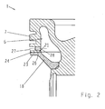
- FIG. 2 The enlarged sectional view according to Fig. 2 shows that the piston pin-side end face 24 of the annular wall 7 has a stepped undercut 25 which corresponds in shape to a mounted on the outer edge 23 of the cooling channel cover 18, also stepped recess 26, so that after the final assembly of the piston 1, the undercut 25 and the recess 26th mesh and contribute to the prevention of load-induced deformations of the outer region of the piston crown 4. Furthermore, in Fig. 2 It can be seen that oil recirculation bores 28 are arranged between the groove 27 for the oil scraper ring (not shown in the figure) and the cooling passage 6.
- cooling channel cover 18 consists of two semicircular cover members 19 and 20. However, they can also be formed in three or more parts. Evident are formed in the outer edge 23 stepped recess 26 and the opening 16 to the inlet and and the opening 16 'for the discharge of cooling oil.
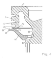
- Fig. 4 Let the type of mounting of the cooling channel cover 18 is illustrated. This is brought first with its inner edge 21 to an edge of the recess 22 and with its outer edge 23 to the end face 24 of the annular wall 7 in abutment, as in Fig. 4 is shown. Subsequently, the inner edge 21 is pressed axially in the direction of the piston head 4, wherein the cooling channel cover 18 is biased and can be pushed radially inward so that it comes to lie with its inner edge 21 in the recess 22. In this position, the cooling channel cover 18 is fixed by the fact that the step 29 formed by the recess 26 snaps into the undercut 25 of the end face 24.
- the cooling channel cover 18 is designed such that it retains a small deformation and thus a permanent bias after the final assembly.
Landscapes
- Engineering & Computer Science (AREA)
- General Engineering & Computer Science (AREA)
- Chemical & Material Sciences (AREA)
- Combustion & Propulsion (AREA)
- Mechanical Engineering (AREA)
- Physics & Mathematics (AREA)
- Fluid Mechanics (AREA)
- Pistons, Piston Rings, And Cylinders (AREA)
Abstract
Description
Die Erfindung betrifft einen Kolben für einen Verbrennungsmotor gemäß Patentanspruch 1.The invention relates to a piston for an internal combustion engine according to claim 1.
Aus der Offenlegungsschrift
Nachteilig ist hierbei, dass im Rahmen der sehr aufwendigen Montage des bekannten Kolbens die Kühlkanalabdeckung zunächst auf die dem Kolbenboden abgewandte Unterseite des Kolbenoberteiles geschoben werden muss, bevor die Ringmutter auf den Ansatz geschraubt und damit die Kühlkanalabdeckung festgeschraubt werden kann. Erst dann kann die weitere Montage des Kolbens erfolgen, bei der der Kolbenschaft auf die Unterseite des Kolbenoberteiles geschoben und mittels einer Kolbenbolzenbüchse daran befestigt wird.
Das Dokument
The document
Hiervon ausgehend liegt der Erfindung die Aufgabe zugrunde, einen einteiligen Kolben mit einem Kühlkanal zu schaffen, der schnell und einfach mit einer Abdeckung verschließbar ist, mit der die Steifigkeit des Kolbens verbessert wird.On this basis, the present invention seeks to provide a one-piece piston with a cooling channel, which is quickly and easily closed with a cover with which the rigidity of the piston is improved.
Gemäß Patentanspruch 1 wird die Aufgabe dadurch gelöst, dass an den Kolbenboden über Nabenabstützungen Bolzennaben angeformt sind, deren Stirnflächen gegenüber dem radial äußeren Rand des Kolbenbodens zurückgesetzt angeordnet sind, dass die Bolzennaben durch Schaftelemente verbunden sind, die über Schaftanbindungen an den Kolbenboden angeformt sind, die im Bereich zwischen den Schaftelementen und dem Kolbenboden konkave Ausnehmungen aufweisen, und dass die Kühlkanalabdeckung aus mindestens zwei teilkreisförmigen Abdeckelementen besteht, deren Innenrand in einer teilweise in die Nabenabstützung und teilweise in die Schaftanbindungen eingearbeiteten Ausnehmung lagert, und deren Außenrand die Ringwand über deren bolzennabenseitige Stirnfläche abstützt.According to claim 1, the object is achieved in that pin bosses are formed on the piston crown via hub supports whose end faces are arranged set back relative to the radially outer edge of the piston head, that the pin bosses are connected by shaft elements which are integrally formed via shank connections to the piston head, the have concave recesses in the region between the shaft elements and the piston head, and that the cooling channel cover consists of at least two part-circular cover elements whose inner edge is supported in a partially incorporated in the hub support and partially in the shaft connections recess, and whose outer edge supports the annular wall on the bolt hub side end face ,
Zweckmäßige Ausgestaltungen der Erfindung sind Gegenstand der Unteransprüche.Advantageous embodiments of the invention are the subject of the dependent claims.
Ein Ausführungsbeispiel der Erfindung wird im Folgenden anhand der Zeichnungen beschrieben. Es zeigen
- Fig. 1
- einen Kolben für einen Verbrennungsmotor mit einer Kühlkanalabdeckung gemäß der Erfindung dargestellt in einem aus zwei Hälften bestehenden Schnittbild, das zwei um 90° versetzte Längsschnitte des Kolbens zeigt,
- Fig. 2
- eine vergrößerte Darstellung des Kühlkanals und der Kühlkanalabdeckung nach deren Endmontage,
- Fig. 3
- eine aus zwei halbkreisförmigen Hälften bestehende Kühlkanalabdeckung und
- Fig. 4
- ein vergrößertes Schnittbild des Kühlkanals mit einer im Rahmen des Zusammenbaus des Kolbens sich ergebenden Anordnung der Kühlkanal- abdeckung.
- Fig. 1
- a piston for an internal combustion engine with a cooling duct cover according to the invention shown in a two-half sectional view showing two 90 ° offset longitudinal sections of the piston,
- Fig. 2
- an enlarged view of the cooling channel and the cooling channel cover after their final assembly,
- Fig. 3
- a consisting of two semicircular halves cooling channel cover and
- Fig. 4
- an enlarged sectional view of the cooling channel with a resulting in the assembly of the piston arrangement of the cooling channel cover.
Über die Nabenabstützungen 9, 9' sind an den Kolbenboden 4 je eine Bolzennabe 10, 10' mit jeweils einer Nabenbohrung 3, 3' angeformt. Die Stirnflächen 11 der Bolzennaben 10, 10' sind gegenüber der Ringwand 7 in Richtung der Kolbenlängsachse 12 zurückgesetzt angeordnet. Die Bolzennaben 10, 10' sind über Schaftelemente 13, 13' miteinander verbunden, die über je eine Schaftanbindung 17, 17' mit dem Kolbenboden 4 verbunden sind. Zwischen den Schaftelementen 13, 13' und dem kolbenbodenseitigen Bereich 14 des Kolbens 1 weist dieser Ausnehmungen 15 auf.About the hub supports 9, 9 'are each a
In Richtung der Bolzennaben 10, 10' ist der Kühlkanal 6 von einer Kühlkanalabdeckung 18 verschlossen, die als massives Stützelement ausgebildet ist und im vorliegenden Ausführungsbeispiel aus zwei halbkreisförmigen Abdeckungselementen 19 und 20 besteht, wie in
Das vergrößerte Schnittbild gemäß
Die in
Anhand von
- 11
- Kolbenpiston
- 22
- Längsachselongitudinal axis
- 3, 3'3, 3 '
- Nabenbohrunghub bore
- 44
- Kolbenbodenpiston crown
- 55
- BrennraummuldeCombustion bowl
- 66
- Kühlkanalcooling channel
- 77
- Ringwandring wall
- 88th
- Ringrippeannular rib
- 9, 9'9, 9 '
- Nabenabstützungboss support
- 10, 10'10, 10 '
- Bolzennabepin boss
- 1111
- Stirnflächeface
- 1212
- Kolbenlängsachsepiston longitudinal axis
- 13, 13'13, 13 '
- Schaftelementshaft element
- 1414
- kolbenbodenseitiger Bereichpiston bottom area
- 1515
- Ausnehmungrecess
- 16, 16'16, 16 '
- Öffnungopening
- 17, 17'17, 17 '
- Schaftanbindungskirt connection
- 1818
- KühlkanalabdeckungCooling channel cover
- 1919
- Abdeckungselementcover member
- 2020
- Abdeckungselementcover member
- 2121
- Innenrand der Kühlkanalabdeckung 18Inner edge of the cooling channel cover 18th
- 2222
- Ausnehmungrecess
- 2323
- Außenrand der Kühlkanalabdeckung 18Outer edge of the cooling channel cover 18th
- 2424
-
Stirnfläche der Ringwand 7End face of the
annular wall 7 - 2525
- Hinterschneidungundercut
- 2626
- Aussparungrecess
- 2727
- Nutgroove
- 2828
- ÖlrücklaufbohrungOil return bore
- 2929
- Stufestep
Claims (4)
- Monobloc piston (1) for an internal combustion engine,- with a piston crown (4),- with two hub supports (9, 9') formed on the piston crown (4) for two pin hubs (10, 10'), wherein the hub supports (9, 9') and the front surfaces (11) of the pin hubs (10, 10') are arranged set back from the radially external edge of the piston crown (4) in the direction of the piston longitudinal axis (12),- with two shaft elements (13, 13') connecting the pin hubs (10, 10'), which are connected with the piston crown (4) by two shaft connections (17, 17'), wherein concave recesses (15) are formed by the shaft connections (17, 17') between the shaft elements (13, 13') and the piston crown (4),- with an annular cooling channel (6) arranged in the edge section of the piston crown (4), of which the radially outer delimitation is formed by an annular wall (7) formed on the piston crown (4), and of which the radially inner delimitation is formed partly by the hub supports (9, 9') and partly by the shaft connections (17, 17'), and- with a cooling channel cover (18) realised as a support element, consisting of at least two part-circular cover elements (19, 20), which closes off the cooling channel (6) towards the side of the pin hubs (10,10'), wherein the inner edge (21) of the cooling channel cover (18) sits in the recess (22) cut partly into the hub supports (9, 9') and partly into the shaft connections (17,17'), characterised in that the cooling channel cover (18) is realised as a support element, and the outer edge (23) of the cooling channel cover (18) supports the annular wall (7) via its front face (24) on the side of the pin hubs.
- Piston (1) for an internal combustion engine according to Claim 1, characterised in that the cooling channel cover (18) consists of two semicircular cover elements (19, 20).
- Piston (1) for an internal combustion engine according to Claim 1 or 2, characterised in that the cooling channel cover (18) is realised in such a way that it can be clamped during assembly under pre-tension between the recess (22) and the front surface (24) of the annular wall (7), and that it retains a deformation and thus a remaining pre-tension after assembly.
- Piston (1) for an internal combustion engine according to Claim 3, characterised in that the front surface (24) of the annular wall (7) has a stepped indentation (25) and the outer edge (23) of the cooling channel cover (18) has a stepped recess (26), which are shaped in such a way that during assembly of the cooling channel cover (18) a step (29) formed by the recess (26) snaps into the indentation (25) of the front surface (24).
Applications Claiming Priority (2)
| Application Number | Priority Date | Filing Date | Title |
|---|---|---|---|
| DE10326456A DE10326456A1 (en) | 2003-06-12 | 2003-06-12 | Pistons for an internal combustion engine |
| PCT/DE2004/001173 WO2004111421A1 (en) | 2003-06-12 | 2004-06-09 | Piston for an internal combustion engine |
Publications (2)
| Publication Number | Publication Date |
|---|---|
| EP1636475A1 EP1636475A1 (en) | 2006-03-22 |
| EP1636475B1 true EP1636475B1 (en) | 2011-04-27 |
Family
ID=33482823
Family Applications (1)
| Application Number | Title | Priority Date | Filing Date |
|---|---|---|---|
| EP04738627A Expired - Lifetime EP1636475B1 (en) | 2003-06-12 | 2004-06-09 | Piston for an internal combustion engine |
Country Status (8)
| Country | Link |
|---|---|
| US (1) | US6957638B2 (en) |
| EP (1) | EP1636475B1 (en) |
| JP (1) | JP4838711B2 (en) |
| KR (1) | KR20060021372A (en) |
| CN (1) | CN100406707C (en) |
| BR (1) | BRPI0411349B1 (en) |
| DE (2) | DE10326456A1 (en) |
| WO (1) | WO2004111421A1 (en) |
Families Citing this family (20)
| Publication number | Priority date | Publication date | Assignee | Title |
|---|---|---|---|---|
| DE10221561A1 (en) * | 2002-05-15 | 2004-01-08 | Mahle Gmbh | Cooled piston for an internal combustion engine |
| US20060086325A1 (en) * | 2004-10-25 | 2006-04-27 | Ipd, Inc. | Two piece cast ferrous crown piston for internal combustion engine |
| US20060086326A1 (en) * | 2004-10-25 | 2006-04-27 | Ipd, Inc. | One piece cast ferrous crown piston for internal combustion engine |
| DE102005037175A1 (en) * | 2005-08-06 | 2007-02-08 | Mahle International Gmbh | Piston for an internal combustion engine and cover ring for the cooling channel of such a piston |
| DE102007027162A1 (en) | 2007-06-13 | 2008-12-18 | Mahle International Gmbh | Two-piece piston for an internal combustion engine |
| US7762227B2 (en) * | 2008-02-19 | 2010-07-27 | Federal Mogul Corporation | Coolable piston for internal combustion engine |
| US8347842B2 (en) * | 2008-02-19 | 2013-01-08 | Federal-Mogul Corporation | Coolable piston for internal combustion engine |
| DE102008055848A1 (en) * | 2008-11-04 | 2010-05-06 | Ks Kolbenschmidt Gmbh | Cooling channel piston of an internal combustion engine with a closure element which closes the cooling channel |
| DE102008062219A1 (en) * | 2008-12-13 | 2010-06-17 | Mahle International Gmbh | Piston for an internal combustion engine |
| USD737861S1 (en) | 2009-10-30 | 2015-09-01 | Caterpillar Inc. | Engine piston |
| GB2487686B (en) * | 2009-10-30 | 2016-02-24 | Caterpillar Inc | Weight balanced internal combustion engine piston |
| DE102010056220A1 (en) * | 2010-12-24 | 2012-06-28 | Mahle International Gmbh | Piston for an internal combustion engine |
| US8955486B2 (en) * | 2012-02-10 | 2015-02-17 | Federal Mogul Corporation | Piston with enhanced cooling gallery |
| DE102012014188A1 (en) * | 2012-07-18 | 2014-01-23 | Mahle International Gmbh | Piston for an internal combustion engine |
| DE102012014195A1 (en) * | 2012-07-18 | 2014-01-23 | Mahle International Gmbh | Piston for an internal combustion engine |
| CN104813014A (en) * | 2012-10-08 | 2015-07-29 | 康珀伦塔芬兰有限公司 | A piston for an internal combustion engine |
| TWI473018B (en) * | 2012-10-23 | 2015-02-11 | Inventec Corp | Network server system and firmware updating method thereof |
| USD768207S1 (en) * | 2014-07-16 | 2016-10-04 | Federal-Mogul Corporation | Piston |
| DE102014015947A1 (en) * | 2014-10-30 | 2016-05-19 | Mahle International Gmbh | Cooling duct cover and piston provided with a cooling channel cover |
| JP2022135346A (en) * | 2021-03-05 | 2022-09-15 | 株式会社豊田自動織機 | piston |
Family Cites Families (12)
| Publication number | Priority date | Publication date | Assignee | Title |
|---|---|---|---|---|
| DE3338419A1 (en) * | 1983-10-22 | 1985-05-02 | Mtu Motoren- Und Turbinen-Union Friedrichshafen Gmbh, 7990 Friedrichshafen | PISTON FOR A PISTON PISTON COMBUSTION ENGINE |
| DE3511852C1 (en) * | 1985-03-30 | 1987-01-02 | Man B & W Diesel Gmbh | Oil-cooled monoblock trunk piston for internal combustion engines |
| DE4039751A1 (en) * | 1990-12-13 | 1992-06-17 | Mahle Gmbh | MULTI-PARTIAL, COOLED PISTON FOR COMBUSTION ENGINES |
| DE4208037C2 (en) * | 1992-03-13 | 1998-03-26 | Mahle Gmbh | Multi-part, cooled piston for internal combustion engines |
| DE19926568A1 (en) * | 1999-06-11 | 2000-12-14 | Mahle Gmbh | Cooled pistons for internal combustion engines |
| DE19962325C2 (en) * | 1999-12-23 | 2003-09-25 | Man B&W Diesel A/S, Copenhagen Sv | reciprocating engine |
| US20010025568A1 (en) * | 2000-03-28 | 2001-10-04 | Mahle Gmbh | One-piece piston |
| WO2001073275A1 (en) * | 2000-03-28 | 2001-10-04 | Federal-Mogul Corporation | Heavy duty piston having oil splash deflector |
| US6401595B1 (en) * | 2000-10-18 | 2002-06-11 | Caterpillar Inc. | Piston for an internal combustion engine and method of assembly |
| US6487773B2 (en) * | 2001-03-23 | 2002-12-03 | Mahle Gmbh | Method of making one-piece piston |
| DE10132447A1 (en) * | 2001-07-04 | 2003-01-09 | Ks Kolbenschmidt Gmbh | Piston with cooling duct in crown has cooling duct open to the bottom and covered with a welded ring |
| US6701875B2 (en) * | 2002-05-31 | 2004-03-09 | Cummins Inc. | Internal combustion engine with piston cooling system and piston therefor |
-
2003
- 2003-06-12 DE DE10326456A patent/DE10326456A1/en not_active Withdrawn
- 2003-12-30 US US10/748,904 patent/US6957638B2/en not_active Expired - Fee Related
-
2004
- 2004-06-09 JP JP2006515671A patent/JP4838711B2/en not_active Expired - Fee Related
- 2004-06-09 DE DE502004012442T patent/DE502004012442D1/en not_active Expired - Lifetime
- 2004-06-09 CN CNB2004800162119A patent/CN100406707C/en not_active Expired - Fee Related
- 2004-06-09 EP EP04738627A patent/EP1636475B1/en not_active Expired - Lifetime
- 2004-06-09 BR BRPI0411349-7A patent/BRPI0411349B1/en not_active IP Right Cessation
- 2004-06-09 KR KR1020057023852A patent/KR20060021372A/en not_active Ceased
- 2004-06-09 WO PCT/DE2004/001173 patent/WO2004111421A1/en not_active Ceased
Also Published As
| Publication number | Publication date |
|---|---|
| EP1636475A1 (en) | 2006-03-22 |
| WO2004111421A1 (en) | 2004-12-23 |
| US6957638B2 (en) | 2005-10-25 |
| JP2006527327A (en) | 2006-11-30 |
| BRPI0411349A (en) | 2006-07-11 |
| CN1806112A (en) | 2006-07-19 |
| BRPI0411349B1 (en) | 2014-09-30 |
| JP4838711B2 (en) | 2011-12-14 |
| CN100406707C (en) | 2008-07-30 |
| US20040250779A1 (en) | 2004-12-16 |
| HK1088940A1 (en) | 2006-11-17 |
| DE10326456A1 (en) | 2004-12-30 |
| KR20060021372A (en) | 2006-03-07 |
| DE502004012442D1 (en) | 2011-06-09 |
Similar Documents
| Publication | Publication Date | Title |
|---|---|---|
| EP1636475B1 (en) | Piston for an internal combustion engine | |
| EP1483503B1 (en) | Fuel pump for an internal combustion engine | |
| EP1828587B1 (en) | Multipart, cooled piston for a combustion engine | |
| EP2342441B1 (en) | Internal combustion engine piston with cooling channel said piston comprising a sealing element sealing the cooling channel | |
| EP1680256B1 (en) | Method for producing a piston for an internal combustion engine | |
| EP1920152B1 (en) | Two-piece piston for an internal combustion engine | |
| EP1636474B1 (en) | Method for producing a one-piece piston for an internal combustion engine | |
| EP1678418B1 (en) | One-piece piston for an internal combustion engine | |
| DE102007060472A1 (en) | Two-piece piston for an internal combustion engine | |
| DE10325914B4 (en) | Piston for an internal combustion engine | |
| WO2005124137A1 (en) | Assembled piston for an internal combustion engine | |
| EP1922478B1 (en) | Liquid-cooled assembled piston | |
| EP1913250B1 (en) | Piston for an internal combustion engine and covering ring for the cooling duct of a piston of said type | |
| WO2007025686A1 (en) | Lightweight piston | |
| EP1819920B1 (en) | Piston for a combustion engine | |
| EP1819922A1 (en) | Two-part piston for a combustion engine | |
| EP1660769B1 (en) | Split piston for an internal combustion engine | |
| EP1819921B1 (en) | Piston for a combustion engine | |
| EP2923122B1 (en) | Piston for an internal combustion engine | |
| DE102004019010A1 (en) | Two-part spring disk for automotive piston exerts different forces around the circumference | |
| DE102009041392A1 (en) | Piston for internal combustion engine, particularly reciprocating piston engine, has upper piston area, which has ring carrier with ring groove and piston bowl | |
| EP3452712B1 (en) | Piston | |
| DE102006045728A1 (en) | Single-piece piston for internal combustion engine, has semicircular unit with lower region lying region of shaft unit on shoulder of shaft unit and at region of front side of bolt bosses respectively on projection of boss connection | |
| EP2011986A2 (en) | One-piece cooling duct piston with two piston segments screwed into another | |
| WO2007031067A1 (en) | Piston for an internal combustion engine |
Legal Events
| Date | Code | Title | Description |
|---|---|---|---|
| PUAI | Public reference made under article 153(3) epc to a published international application that has entered the european phase |
Free format text: ORIGINAL CODE: 0009012 |
|
| 17P | Request for examination filed |
Effective date: 20051217 |
|
| AK | Designated contracting states |
Kind code of ref document: A1 Designated state(s): DE FR GB IT |
|
| DAX | Request for extension of the european patent (deleted) | ||
| RBV | Designated contracting states (corrected) |
Designated state(s): DE FR GB IT |
|
| GRAP | Despatch of communication of intention to grant a patent |
Free format text: ORIGINAL CODE: EPIDOSNIGR1 |
|
| GRAS | Grant fee paid |
Free format text: ORIGINAL CODE: EPIDOSNIGR3 |
|
| GRAA | (expected) grant |
Free format text: ORIGINAL CODE: 0009210 |
|
| AK | Designated contracting states |
Kind code of ref document: B1 Designated state(s): DE FR GB IT |
|
| REG | Reference to a national code |
Ref country code: GB Ref legal event code: FG4D Free format text: NOT ENGLISH |
|
| REF | Corresponds to: |
Ref document number: 502004012442 Country of ref document: DE Date of ref document: 20110609 Kind code of ref document: P |
|
| REG | Reference to a national code |
Ref country code: DE Ref legal event code: R096 Ref document number: 502004012442 Country of ref document: DE Effective date: 20110609 |
|
| PLBE | No opposition filed within time limit |
Free format text: ORIGINAL CODE: 0009261 |
|
| STAA | Information on the status of an ep patent application or granted ep patent |
Free format text: STATUS: NO OPPOSITION FILED WITHIN TIME LIMIT |
|
| 26N | No opposition filed |
Effective date: 20120130 |
|
| REG | Reference to a national code |
Ref country code: DE Ref legal event code: R097 Ref document number: 502004012442 Country of ref document: DE Effective date: 20120130 |
|
| REG | Reference to a national code |
Ref country code: FR Ref legal event code: PLFP Year of fee payment: 12 |
|
| PGFP | Annual fee paid to national office [announced via postgrant information from national office to epo] |
Ref country code: GB Payment date: 20150622 Year of fee payment: 12 |
|
| PGFP | Annual fee paid to national office [announced via postgrant information from national office to epo] |
Ref country code: FR Payment date: 20150622 Year of fee payment: 12 |
|
| PGFP | Annual fee paid to national office [announced via postgrant information from national office to epo] |
Ref country code: DE Payment date: 20150630 Year of fee payment: 12 |
|
| PGFP | Annual fee paid to national office [announced via postgrant information from national office to epo] |
Ref country code: IT Payment date: 20150630 Year of fee payment: 12 |
|
| REG | Reference to a national code |
Ref country code: DE Ref legal event code: R119 Ref document number: 502004012442 Country of ref document: DE |
|
| GBPC | Gb: european patent ceased through non-payment of renewal fee |
Effective date: 20160609 |
|
| REG | Reference to a national code |
Ref country code: FR Ref legal event code: ST Effective date: 20170228 |
|
| PG25 | Lapsed in a contracting state [announced via postgrant information from national office to epo] |
Ref country code: FR Free format text: LAPSE BECAUSE OF NON-PAYMENT OF DUE FEES Effective date: 20160630 Ref country code: DE Free format text: LAPSE BECAUSE OF NON-PAYMENT OF DUE FEES Effective date: 20170103 |
|
| PG25 | Lapsed in a contracting state [announced via postgrant information from national office to epo] |
Ref country code: GB Free format text: LAPSE BECAUSE OF NON-PAYMENT OF DUE FEES Effective date: 20160609 |
|
| PG25 | Lapsed in a contracting state [announced via postgrant information from national office to epo] |
Ref country code: IT Free format text: LAPSE BECAUSE OF NON-PAYMENT OF DUE FEES Effective date: 20160609 |