EP1636473B1 - Piston for a combustion engine and casting method for the production thereof - Google Patents
Piston for a combustion engine and casting method for the production thereof Download PDFInfo
- Publication number
- EP1636473B1 EP1636473B1 EP04738605A EP04738605A EP1636473B1 EP 1636473 B1 EP1636473 B1 EP 1636473B1 EP 04738605 A EP04738605 A EP 04738605A EP 04738605 A EP04738605 A EP 04738605A EP 1636473 B1 EP1636473 B1 EP 1636473B1
- Authority
- EP
- European Patent Office
- Prior art keywords
- piston
- casting
- recesses
- hubs
- area
- Prior art date
- Legal status (The legal status is an assumption and is not a legal conclusion. Google has not performed a legal analysis and makes no representation as to the accuracy of the status listed.)
- Expired - Fee Related
Links
Images

Classifications
-
- B—PERFORMING OPERATIONS; TRANSPORTING
- B22—CASTING; POWDER METALLURGY
- B22C—FOUNDRY MOULDING
- B22C9/00—Moulds or cores; Moulding processes
- B22C9/10—Cores; Manufacture or installation of cores
- B22C9/105—Salt cores
-
- B—PERFORMING OPERATIONS; TRANSPORTING
- B22—CASTING; POWDER METALLURGY
- B22D—CASTING OF METALS; CASTING OF OTHER SUBSTANCES BY THE SAME PROCESSES OR DEVICES
- B22D15/00—Casting using a mould or core of which a part significant to the process is of high thermal conductivity, e.g. chill casting; Moulds or accessories specially adapted therefor
- B22D15/02—Casting using a mould or core of which a part significant to the process is of high thermal conductivity, e.g. chill casting; Moulds or accessories specially adapted therefor of cylinders, pistons, bearing shells or like thin-walled objects
-
- B—PERFORMING OPERATIONS; TRANSPORTING
- B22—CASTING; POWDER METALLURGY
- B22D—CASTING OF METALS; CASTING OF OTHER SUBSTANCES BY THE SAME PROCESSES OR DEVICES
- B22D19/00—Casting in, on, or around objects which form part of the product
- B22D19/0009—Cylinders, pistons
- B22D19/0027—Cylinders, pistons pistons
-
- F—MECHANICAL ENGINEERING; LIGHTING; HEATING; WEAPONS; BLASTING
- F02—COMBUSTION ENGINES; HOT-GAS OR COMBUSTION-PRODUCT ENGINE PLANTS
- F02F—CYLINDERS, PISTONS OR CASINGS, FOR COMBUSTION ENGINES; ARRANGEMENTS OF SEALINGS IN COMBUSTION ENGINES
- F02F3/00—Pistons
-
- Y—GENERAL TAGGING OF NEW TECHNOLOGICAL DEVELOPMENTS; GENERAL TAGGING OF CROSS-SECTIONAL TECHNOLOGIES SPANNING OVER SEVERAL SECTIONS OF THE IPC; TECHNICAL SUBJECTS COVERED BY FORMER USPC CROSS-REFERENCE ART COLLECTIONS [XRACs] AND DIGESTS
- Y10—TECHNICAL SUBJECTS COVERED BY FORMER USPC
- Y10T—TECHNICAL SUBJECTS COVERED BY FORMER US CLASSIFICATION
- Y10T29/00—Metal working
- Y10T29/49—Method of mechanical manufacture
- Y10T29/49229—Prime mover or fluid pump making
- Y10T29/49249—Piston making
- Y10T29/49256—Piston making with assembly or composite article making
- Y10T29/49261—Piston making with assembly or composite article making by composite casting or molding
Definitions
- the invention relates to a piston for an internal combustion engine according to the preamble of claim 1 and a method for its production according to the preamble of claim 2.
- a piston is known whose formed on a cylindrically shaped, upper portion of the piston pin bosses are set back relative to the edge of the upper region, so that when pouring the piston in the bottom of the overhang formed thereby near the pin bosses recesses can be formed.
- a mold is used which contains a pivotable window insert with a casting core per recess, but which can only produce those recesses from which the casting core can be easily removed after casting.
- the disadvantage here is that a very complicated mechanism is required to keep the casting mold during casting of the piston exactly in the space provided and move away obliquely downwards from the piston after casting and pull it out of the molding.
- the known from the prior art molding no incisions, which allows a production of ribs in the recess, which brings about the further disadvantage that the piston known from the latter prior art has only a low mechanical strength.
- the invention has the object to avoid the disadvantages of the cited prior art.
- the problem is solved with the features in the characteristics of the main claim and the dependent claim.
- An expedient embodiment of the invention is the subject of the dependent claim.
- the subject matter of the second claim combines the advantages of a hinged window insert, which can be made on casting technology simple way recesses for which linearly movable slide are unsuitable, with the advantages of a salt core, the unlimited potential for possibilities of designing cavities in the piston offers.
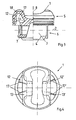
- a piston 1 is shown in half section, the left half of which lies on the longitudinal axis 2 of a piston pin, not shown, section of the piston and the right half of a side view of the piston 1, in which a coated portion 3 of a piston shaft 4 can be seen.
- the piston 1 is designed as a box piston, ie, below a circular cylindrical and the piston rings receiving, upper portion 5 is a lower portion 6, which has an approximately box-shaped cross-section, in which the hubs 7 and the box walls in the region of the hubs 7 to the piston center axis are drawn in, and in which only the lying in the region of the pressure and the counterpressure side shaft wall sections in section have the shape of segments of a circle whose diameter corresponds to the piston diameter.
- the piston 1 has two elevations 9 and 10, which are arranged on both sides of a combustion chamber trough 11 formed in the piston crown.
- elevations 9 and 10 of the center of gravity of the piston 1 is not displaced too far upwards in the direction of the combustion chamber trough 11, are in the casting of the piston 1 in the combustion chamber troughs 9, 10 to the lower portion 6 of the piston 1 open recesses 12 and also formed in the region between the hubs 7 and the upper portion 5 undercuts 13 which are formed nose-shaped in cross section in the present embodiment and each aligned to the piston center axis 8 out but also any other shape suitable for reducing the weight of the piston.
- the mass center of gravity of the piston 1 in the direction of the hubs 7 is displaced by the material saved thereby.
- the casting mold for casting the piston 1 has a pivotable window insert 14 for each of the recesses 12 to be produced in the two elevations 9 and 10.
- a prefabricated salt mold part 15 is applied before the casting of the piston 1 on the window insert 14, the shape of which is identical to the shape of the recess 12 including the undercut 13.
- Das Salt mold part 15 is secured against rotation on the window insert 14 via two conical projections 16 arranged on the window insert 14, onto which the salt mold part 15 is slipped.
- the window insert 14 is shown in section, which is why only one of the two extensions 16 can be seen. With pivoted-in window insert 14 and salt molding 15 mounted thereon, the piston blank 1 is poured.
- FIG. 3 illustrated piston blank 1 which has the recesses 12 with the undercuts 13, wherein these recesses 12, as well as in FIG. 4 are divided by ribs 17,17 ', which serve to improve the dimensional stability of the walls 18 of the elevations 9 and 10. This allows to make the walls 18 very thin, thereby achieving improved cooling of the upper portion 5 of the piston 1 by spraying with cooling oil.
- the bottom view of the piston according to FIG. 4 shows the kidney-shaped configuration of the recesses 12, 12 'with the dashed lines undercuts 13, 13', which are divided in the present embodiment of two ribs 17, 17 '.
- the shape and the arrangement of the ribs 17, 17 'in a simple manner by a corresponding design of the salt-molded part 15 are taken into account.
- the shape of the salt mold part 15 corresponds to the negative shape shown in the figures of the recesses 12, 12 'and undercuts 13, 13'.
Description
Die Erfindung betrifft einen Kolben für einen Verbrennungsmotor nach dem Oberbegriff des Anspruches 1 und ein Verfahren zu dessen Herstellung nach dem Oberbegriff des Anspruches 2.The invention relates to a piston for an internal combustion engine according to the preamble of
Aus der Offenlegungsschrift
Aus der Offenlegungsschrift
Nachteilig ist hierbei, dass ein sehr aufwendiger Mechanismus erforderlich ist, um das Gießwerkzeug beim Gießen des Kolbens exakt in der dafür vorgesehenen Position zu halten und nach dem Guss schräg nach unten vom Kolben wegzubewegen und aus dem Formkörper herauszuziehen. Zudem weist das aus dem Stand der Technik bekannte Formteil keine Einschnitte auf, die eine Herstellung von Rippen in der Ausnehmung ermöglicht, was den weiteren Nachteil mit sich bringt, dass der aus dem letztgenannten Stand der Technik bekannte Kolben nur eine geringe mechanische Festigkeit aufweist.The disadvantage here is that a very complicated mechanism is required to keep the casting mold during casting of the piston exactly in the space provided and move away obliquely downwards from the piston after casting and pull it out of the molding. In addition, the known from the prior art molding no incisions, which allows a production of ribs in the recess, which brings about the further disadvantage that the piston known from the latter prior art has only a low mechanical strength.
Aus der Europäischen Patentanmeldung
Hiervon ausgehend liegt der Erfindung die Aufgabe zugrunde, die Nachteile des genannten Stand der Technik zu vermeiden. Gelöst wird die Aufgabe mit den im Kennzeichen des Hauptanspruches und des Nebenanspruches stehenden Merkmalen. Eine zweckmäßige Ausgestaltung der Erfindung ist Gegenstand des Unteranspruches.On this basis, the invention has the object to avoid the disadvantages of the cited prior art. The problem is solved with the features in the characteristics of the main claim and the dependent claim. An expedient embodiment of the invention is the subject of the dependent claim.
Der Gegenstand des 2. Anspruchs kombiniert die Vorteile eines schwenkbaren Fenstereinsatzes, mit dem auf gießtechnisch einfache Weise Aussparungen hergestellt werden können, für die linear bewegliche Schieber ungeeignet sind, mit den Vorteilen eines Salzkernes, der ein unbegrenztes Potenzial an Möglichkeiten der Gestaltung von Hohlräumen im Kolben bietet.The subject matter of the second claim combines the advantages of a hinged window insert, which can be made on casting technology simple way recesses for which linearly movable slide are unsuitable, with the advantages of a salt core, the unlimited potential for possibilities of designing cavities in the piston offers.
Ein Ausführungsbeispiel der Erfindung wird im Folgenden anhand der Zeichnungen beschrieben. Es zeigen
- Fig. 1
- einen teilweise geschnittenen Kolben nach dem Guss mit eingesetztem Salzformteil, befestigt auf einem schwenkbaren Fenstereinsatz,
- Fig. 2
- den Kolben mit eingesetztem Salzformteil und auswärts geschwenktem Fenstereinsatz, der sich vom Salzformteil gelöst hat,
- Fig. 3
- den teilweise geschnittenen Kolben, nachdem das Salzformteil ausgewaschen ist, und
- Fig. 4
- eine Untersicht des Kolbens gemäß der Erfindung.
- Fig. 1
- a partially cut piston after casting with inserted salt molding, mounted on a pivoting window insert,
- Fig. 2
- the piston with inserted salt molding and outwardly pivoted window insert, which has detached from the salt molding,
- Fig. 3
- the partially cut piston after the salt molding is washed out, and
- Fig. 4
- a bottom view of the piston according to the invention.
In
Der Kolben 1 weist zwei Überhöhungen 9 und 10 auf, die beiderseits einer im Kolbenboden eingeformten Brennraummulde 11 angeordnet sind. Damit durch diese Überhöhungen 9 und 10 der Schwerpunkt des Kolbens 1 nicht zu weit nach oben in Richtung Brennraummulde 11 verlagert wird, werden beim Gießen des Kolbens 1 in die Brennraummulden 9, 10 zum unteren Bereich 6 des Kolbens 1 hin offene Aussparungen 12 und zudem in den Bereich zwischen den Naben 7 und dem oberen Bereich 5 Hinterschneidungen 13 eingeformt, die im vorliegenden Ausführungsbeispiel im Querschnitt nasenförmig ausgebildet und jeweils zur Kolbenmittelachse 8 hin ausgerichtet sind, die aber auch jede andere Form haben können, die dazu geeignet ist, das Gewicht des Kolbens zu verringern. Durch das hierbei eingesparte Material wird zudem der Massenschwerpunkt des Kolbens 1 in Richtung Naben 7 verlagert.The
Hierbei weist die Gießform zum Gießen des Kolbens 1 für jede der in den beiden Überhöhungen 9 und 10 zu erzeugenden Aussparungen 12 einen schwenkbaren Fenstereinsatz 14 auf. Um hiermit die Hinterschneidungen 13 in den oberen Bereich 5 des Kolbens 1 einformen zu können, wird vor dem Gießen des Kolbens 1 auf den Fenstereinsatz 14 ein vorgefertigtes Salzformteil 15 aufgebracht, dessen Form identisch ist mit der Form der Aussparung 12 einschließlich der Hinterschneidung 13. Das Salzformteil 15 wird auf dem Fenstereinsatz 14 verdrehsicher über zwei auf dem Fenstereinsatz 14 angeordnete kegelförmigen Fortsätze 16 befestigt, auf die das Salzformteil 15 aufgesteckt wird. In den
Im Anschluss an den Gießvorgang wird gemäß
Hierbei ergibt sich der in
Die Untersicht des Kolbens gemäß
- 11
- Kolben, KolbenrohlingPiston, piston blank
- 22
- Bolzenachsepin axis
- 33
- beschichteter Bereichcoated area
- 44
- Kolbenschaftpiston shaft
- 55
- oberer Bereichupper area
- 66
- unterer Bereichlower area
- 77
- Nabehub
- 88th
- KolbenmittelachsePiston central axis
- 99
- seitliche Überhöhunglateral elevation
- 1010
- seitliche Überhöhunglateral elevation
- 1111
- BrennraummuldeCombustion bowl
- 12, 12'12, 12 '
- Aussparungrecess
- 13, 13'13, 13 '
- Hinterschneidungundercut
- 1414
- FenstereinsatzFenstereinsatz
- 1515
- SalzformteilSalt form part
- 1616
- kegelförmiger Fortsatzcone-shaped extension
- 17, 17'17, 17 '
- Rippenribs
- 1818
- Wandwall
Claims (3)
- A piston (1) for an internal combustion engine, said piston consisting of- an approximately circular cylindrical upper area (5) for receiving annular grooves and- a lower area (6) having two hubs (7) for receiving a piston pin, which hubs are set back toward the piston central axis (8),- wherein in the upper area (5), recesses (12, 12') are arranged in the area of the hubs (7), which recesses are open toward the lower area (6) and have molded undercuts (13, 13') in the area between the hubs (7) and the upper area (5),characterized in that the recesses (12, 12') are subdivided in each case by at least one rib (17, 17') which is arranged in the radial direction.
- A casting method for producing a piston, wherein a casting mold having pivotable window inserts (14) is used for producing recesses (12, 12'),
comprising the following method steps:- producing salt mold parts (15) by means of which, when casting the piston (1), the recesses (12, 12') and also undercuts (13, 13') projecting into the area between the hubs (7) and the upper area (5) of the piston (1) can be generated,- introducing notches into the salt mold parts (15) for producing ribs (17, 17') arranged in the recesses (12, 12') and in the undercuts (13, 13') when casting the piston (1),- securing the salt mold parts (15) on the respective window inserts (14),- casting the piston (1),- pivoting the window inserts (14) away from the finished casted piston (1), wherein the salt mold parts disengage from the window inserts and remain within the piston, and- washing the salt mold parts (15) out of the piston (1). - The casting method according to claim 2, characterized in that the window inserts (14) have in each case at least two conical extensions (16) onto which the respective salt mold parts (15) are attached.
Applications Claiming Priority (2)
| Application Number | Priority Date | Filing Date | Title |
|---|---|---|---|
| DE10325917A DE10325917A1 (en) | 2003-06-07 | 2003-06-07 | Piston for an internal combustion engine and casting process for its production |
| PCT/DE2004/001151 WO2004111419A1 (en) | 2003-06-07 | 2004-06-07 | Piston for a combustion engine and casting method for the production thereof |
Publications (3)
| Publication Number | Publication Date |
|---|---|
| EP1636473A1 EP1636473A1 (en) | 2006-03-22 |
| EP1636473B1 true EP1636473B1 (en) | 2012-12-19 |
| EP1636473B2 EP1636473B2 (en) | 2016-03-16 |
Family
ID=33546538
Family Applications (1)
| Application Number | Title | Priority Date | Filing Date |
|---|---|---|---|
| EP04738605.7A Expired - Fee Related EP1636473B2 (en) | 2003-06-07 | 2004-06-07 | Piston for a combustion engine and casting method for the production thereof |
Country Status (7)
| Country | Link |
|---|---|
| US (1) | US7213562B2 (en) |
| EP (1) | EP1636473B2 (en) |
| JP (1) | JP4741479B2 (en) |
| KR (1) | KR101119174B1 (en) |
| BR (1) | BRPI0411089B1 (en) |
| DE (1) | DE10325917A1 (en) |
| WO (1) | WO2004111419A1 (en) |
Families Citing this family (14)
| Publication number | Priority date | Publication date | Assignee | Title |
|---|---|---|---|---|
| US20080128946A1 (en) * | 2005-02-10 | 2008-06-05 | Boye David J | Mold assembly for lightweight pistons |
| JP2006258013A (en) * | 2005-03-18 | 2006-09-28 | Toyota Motor Corp | Piston for internal combustion engine, and internal combustion engine having the same |
| DE102010064078A1 (en) * | 2010-12-23 | 2012-06-28 | Federal-Mogul Nürnberg GmbH | Casting device for a piston for an internal combustion engine and method for opening and / or closing a casting device |
| DE102011085448A1 (en) * | 2011-10-28 | 2013-05-02 | Ks Kolbenschmidt Gmbh | Piston and connecting rod for an internal combustion engine |
| DE102012203570A1 (en) * | 2012-03-07 | 2013-09-12 | Mahle International Gmbh | Cast light metal piston, especially an aluminum piston |
| DE102012204480A1 (en) * | 2012-03-21 | 2013-09-26 | Mahle International Gmbh | Process for the preparation of a cooled ring carrier |
| US8459332B1 (en) * | 2012-07-09 | 2013-06-11 | Kevin M. O'Connor | Piston outer panel mold and method of constructing a piston and forming an undercut cooling gallery of a piston therewith |
| DE102013013962A1 (en) * | 2013-08-23 | 2015-02-26 | Mahle International Gmbh | Assembly of a piston and a Anspritzdüse for an internal combustion engine |
| US9662707B2 (en) * | 2013-09-27 | 2017-05-30 | Honda Foundry Co., Ltd. | Piston casting method and piston casting device |
| KR101634788B1 (en) * | 2015-09-04 | 2016-06-30 | 동양피스톤 주식회사 | eco mold device for producing piston and mold device for producing piston and piston producing method |
| KR101615274B1 (en) * | 2015-09-04 | 2016-04-25 | 동양피스톤 주식회사 | eco mold device for producing piston and mold device for producing piston and piston producing method |
| KR101896806B1 (en) * | 2016-12-15 | 2018-09-07 | 현대자동차주식회사 | Alluminum alloy for insert ring, alluminum insert ring using the same and piston manufacturing method using the same |
| SE543272C2 (en) | 2019-03-06 | 2020-11-10 | Husqvarna Ab | Engine piston, engine, hand-held tool, and method of manufacturing an engine piston |
| CN111957899A (en) * | 2020-07-13 | 2020-11-20 | 华域科尔本施密特活塞有限公司 | Preparation method of lightweight piston structure |
Family Cites Families (27)
| Publication number | Priority date | Publication date | Assignee | Title |
|---|---|---|---|---|
| GB617224A (en) | 1946-08-21 | 1949-02-02 | Harry Ralph Ricardo | Improvements in or relating to pistons |
| GB1055737A (en) * | 1964-03-25 | 1967-01-18 | Wellworthy Ltd | Improvements in casting processes |
| FR2079873A5 (en) | 1970-02-16 | 1971-11-12 | Semt | |
| CS201273B1 (en) | 1978-06-22 | 1980-10-31 | Miroslav Novotny | Piston from the alloyed perlitic plastic cast iron for the ignition engines |
| WO1980002308A1 (en) | 1979-04-23 | 1980-10-30 | Caterpillar Tractor Co | Oil cooled piston |
| DE3338419A1 (en) | 1983-10-22 | 1985-05-02 | Mtu Motoren- Und Turbinen-Union Friedrichshafen Gmbh, 7990 Friedrichshafen | PISTON FOR A PISTON PISTON COMBUSTION ENGINE |
| GB8413800D0 (en) * | 1984-05-30 | 1984-07-04 | Ae Plc | Manufacture of pistons |
| DE3424522A1 (en) | 1984-07-04 | 1986-01-16 | Oxytechnik Gesellschaft für Systemtechnik mbH, 6236 Eschborn | Pipe silo |
| JPS61157122A (en) * | 1984-12-28 | 1986-07-16 | Hitachi Denshi Ltd | Modulator-demodulator |
| JPS61157122U (en) * | 1985-03-20 | 1986-09-29 | ||
| DE3721021A1 (en) * | 1986-06-27 | 1988-01-21 | Aisin Seiki | METHOD FOR PRODUCING AN INTERNAL COMBUSTION ENGINE PISTON |
| DE3831285A1 (en) * | 1987-09-17 | 1989-04-06 | Aisin Seiki | METHOD FOR PRODUCING A PISTON OF AN INTERNAL COMBUSTION ENGINE |
| GB8824222D0 (en) * | 1988-10-15 | 1988-11-23 | Wellworthy Ltd | Pistons |
| JPH0442246A (en) * | 1990-06-08 | 1992-02-12 | Toshiba Corp | Image forming device |
| JPH0442246U (en) * | 1990-08-09 | 1992-04-09 | ||
| DE4434994C2 (en) | 1994-09-30 | 1998-02-19 | Porsche Ag | Pistons for internal combustion engines |
| US5692430A (en) | 1995-06-08 | 1997-12-02 | Caterpillar Inc. | Articulated piston apparatus including a cooling gallery |
| US5794582A (en) * | 1995-09-26 | 1998-08-18 | Isuzu Motors Ltd. | Connecting structure of piston and connecting rod |
| JPH09151786A (en) * | 1995-11-30 | 1997-06-10 | Aisin Seiki Co Ltd | Manufacture of piston for internal combustion engine |
| US5979298A (en) * | 1997-05-08 | 1999-11-09 | Zellner Pistons, Llc | Cooling gallery for pistons |
| DE19747944A1 (en) | 1997-10-30 | 1999-05-06 | Mahle Gmbh | Piston with a central cold room |
| DE19922809A1 (en) * | 1999-05-19 | 2000-11-23 | Mahle Gmbh | Casting process used in the production of pistons comprises producing recesses by cores that move on deformation |
| DE19926568A1 (en) * | 1999-06-11 | 2000-12-14 | Mahle Gmbh | Cooled pistons for internal combustion engines |
| FR2800142B1 (en) * | 1999-09-29 | 2002-06-21 | Valeo | HYDROKINETIC COUPLING APPARATUS HAVING IMPROVED FREE REACTOR WHEEL |
| DE10003821C5 (en) * | 2000-01-28 | 2008-06-26 | Ks Kolbenschmidt Gmbh | Piston, in particular a light metal piston for an internal combustion engine |
| DE10013395C1 (en) | 2000-03-17 | 2001-08-02 | Ks Kolbenschmidt Gmbh | Method for producing a one-piece cooling channel piston, in particular for a diesel engine, and a one-piece cooling channel piston produced thereafter |
| DE10142980A1 (en) * | 2001-09-01 | 2003-03-27 | Ks Kolbenschmidt Gmbh | Manufacturing method for single piece piston with undercut piston ring, by providing profiled body inside casting tool and removing it after piston has been cast |
-
2003
- 2003-06-07 DE DE10325917A patent/DE10325917A1/en not_active Withdrawn
-
2004
- 2004-06-07 US US10/559,884 patent/US7213562B2/en active Active
- 2004-06-07 KR KR1020057023488A patent/KR101119174B1/en active IP Right Grant
- 2004-06-07 WO PCT/DE2004/001151 patent/WO2004111419A1/en active Application Filing
- 2004-06-07 JP JP2006515667A patent/JP4741479B2/en not_active Expired - Fee Related
- 2004-06-07 BR BRPI0411089-7A patent/BRPI0411089B1/en not_active IP Right Cessation
- 2004-06-07 EP EP04738605.7A patent/EP1636473B2/en not_active Expired - Fee Related
Also Published As
| Publication number | Publication date |
|---|---|
| BRPI0411089B1 (en) | 2015-07-28 |
| WO2004111419A1 (en) | 2004-12-23 |
| BRPI0411089A (en) | 2006-07-25 |
| DE10325917A1 (en) | 2005-03-31 |
| EP1636473A1 (en) | 2006-03-22 |
| KR101119174B1 (en) | 2012-02-21 |
| WO2004111419B1 (en) | 2005-04-07 |
| JP2006527325A (en) | 2006-11-30 |
| EP1636473B2 (en) | 2016-03-16 |
| KR20060035615A (en) | 2006-04-26 |
| JP4741479B2 (en) | 2011-08-03 |
| US7213562B2 (en) | 2007-05-08 |
| US20060118076A1 (en) | 2006-06-08 |
Similar Documents
| Publication | Publication Date | Title |
|---|---|---|
| EP1636473B1 (en) | Piston for a combustion engine and casting method for the production thereof | |
| EP2202044B2 (en) | Method for injection moulding of a pump propeller | |
| DE102008040873A1 (en) | Method for producing an electric machine and electric machine for a hybrid vehicle | |
| EP3401037B1 (en) | Mold for producing a casting core | |
| DE102014206870A1 (en) | Bearing assembly and method for its manufacture | |
| DE4011784C2 (en) | Molding tool | |
| EP1636474A2 (en) | Method for producing a one-piece piston for an internal combustion engine | |
| EP3267041B1 (en) | Method and tool for producing an impeller | |
| EP3727723A1 (en) | Method for producing a moulded part and feeder insert for use in such a method | |
| EP3927483A1 (en) | One-piece feeder body for use while casting metals | |
| DE3231998A1 (en) | PISTON WITH INSERT | |
| EP3595829B1 (en) | Device for shooting a casting core | |
| DE4137805A1 (en) | METHOD FOR PRODUCING A PISTON VALVE AND DEVICE FOR CARRYING OUT THE METHOD | |
| EP1815123B1 (en) | Piston with a cooling duct for a combustion engine and method for producing the piston | |
| DE102010033675A1 (en) | Method of overmolding and molding for its implementation | |
| DE19744361A1 (en) | Plastic fuel filter | |
| DE3047621A1 (en) | "MOLD INLET WHICH ALLOWS THE INTRODUCTION OF A STIFF MOLD INTO A MOLDING SPACE" | |
| DE10129046A1 (en) | Lightweight piston for IC engine has a void filled with a lighter material than that of the piston | |
| DE10142980A1 (en) | Manufacturing method for single piece piston with undercut piston ring, by providing profiled body inside casting tool and removing it after piston has been cast | |
| WO2020156920A1 (en) | Method for producing a cast vehicle wheel | |
| DE10014611C1 (en) | Injection molding tool and method for producing an inner molded part thereof | |
| DE102019102449A1 (en) | One-piece feeder body for use in casting metals | |
| EP3094432B1 (en) | Casting mold for sand casting for producing a brake caliper | |
| DE19615309A1 (en) | Injection moulding and joining of objects formed by two separate sections | |
| EP1232050B1 (en) | Lost core method for producing a hollow structure |
Legal Events
| Date | Code | Title | Description |
|---|---|---|---|
| PUAI | Public reference made under article 153(3) epc to a published international application that has entered the european phase |
Free format text: ORIGINAL CODE: 0009012 |
|
| 17P | Request for examination filed |
Effective date: 20051217 |
|
| AK | Designated contracting states |
Kind code of ref document: A1 Designated state(s): DE FR GB IT |
|
| DAX | Request for extension of the european patent (deleted) | ||
| RBV | Designated contracting states (corrected) |
Designated state(s): DE FR GB IT |
|
| GRAP | Despatch of communication of intention to grant a patent |
Free format text: ORIGINAL CODE: EPIDOSNIGR1 |
|
| GRAS | Grant fee paid |
Free format text: ORIGINAL CODE: EPIDOSNIGR3 |
|
| GRAA | (expected) grant |
Free format text: ORIGINAL CODE: 0009210 |
|
| AK | Designated contracting states |
Kind code of ref document: B1 Designated state(s): DE FR GB IT |
|
| REG | Reference to a national code |
Ref country code: GB Ref legal event code: FG4D Free format text: NOT ENGLISH |
|
| REG | Reference to a national code |
Ref country code: DE Ref legal event code: R096 Ref document number: 502004013944 Country of ref document: DE Effective date: 20130221 |
|
| PLBI | Opposition filed |
Free format text: ORIGINAL CODE: 0009260 |
|
| PLAX | Notice of opposition and request to file observation + time limit sent |
Free format text: ORIGINAL CODE: EPIDOSNOBS2 |
|
| 26 | Opposition filed |
Opponent name: KS KOLBENSCHMIDT GMBH Effective date: 20130918 |
|
| REG | Reference to a national code |
Ref country code: DE Ref legal event code: R026 Ref document number: 502004013944 Country of ref document: DE Effective date: 20130918 |
|
| PG25 | Lapsed in a contracting state [announced via postgrant information from national office to epo] |
Ref country code: IT Free format text: LAPSE BECAUSE OF FAILURE TO SUBMIT A TRANSLATION OF THE DESCRIPTION OR TO PAY THE FEE WITHIN THE PRESCRIBED TIME-LIMIT Effective date: 20121219 |
|
| PLBB | Reply of patent proprietor to notice(s) of opposition received |
Free format text: ORIGINAL CODE: EPIDOSNOBS3 |
|
| REG | Reference to a national code |
Ref country code: FR Ref legal event code: PLFP Year of fee payment: 12 |
|
| PUAH | Patent maintained in amended form |
Free format text: ORIGINAL CODE: 0009272 |
|
| STAA | Information on the status of an ep patent application or granted ep patent |
Free format text: STATUS: PATENT MAINTAINED AS AMENDED |
|
| 27A | Patent maintained in amended form |
Effective date: 20160316 |
|
| AK | Designated contracting states |
Kind code of ref document: B2 Designated state(s): DE FR GB IT |
|
| REG | Reference to a national code |
Ref country code: DE Ref legal event code: R102 Ref document number: 502004013944 Country of ref document: DE |
|
| REG | Reference to a national code |
Ref country code: FR Ref legal event code: PLFP Year of fee payment: 13 |
|
| REG | Reference to a national code |
Ref country code: FR Ref legal event code: PLFP Year of fee payment: 14 |
|
| REG | Reference to a national code |
Ref country code: FR Ref legal event code: PLFP Year of fee payment: 15 |
|
| PGFP | Annual fee paid to national office [announced via postgrant information from national office to epo] |
Ref country code: FR Payment date: 20180629 Year of fee payment: 15 |
|
| PGFP | Annual fee paid to national office [announced via postgrant information from national office to epo] |
Ref country code: DE Payment date: 20180831 Year of fee payment: 15 Ref country code: GB Payment date: 20180629 Year of fee payment: 15 |
|
| REG | Reference to a national code |
Ref country code: DE Ref legal event code: R119 Ref document number: 502004013944 Country of ref document: DE |
|
| GBPC | Gb: european patent ceased through non-payment of renewal fee |
Effective date: 20190607 |
|
| PG25 | Lapsed in a contracting state [announced via postgrant information from national office to epo] |
Ref country code: GB Free format text: LAPSE BECAUSE OF NON-PAYMENT OF DUE FEES Effective date: 20190607 Ref country code: DE Free format text: LAPSE BECAUSE OF NON-PAYMENT OF DUE FEES Effective date: 20200101 |
|
| PG25 | Lapsed in a contracting state [announced via postgrant information from national office to epo] |
Ref country code: FR Free format text: LAPSE BECAUSE OF NON-PAYMENT OF DUE FEES Effective date: 20190630 |