EP1635103A1 - Raccord détachable à fiche pour des tuyaux ou similaires - Google Patents
Raccord détachable à fiche pour des tuyaux ou similaires Download PDFInfo
- Publication number
- EP1635103A1 EP1635103A1 EP05017154A EP05017154A EP1635103A1 EP 1635103 A1 EP1635103 A1 EP 1635103A1 EP 05017154 A EP05017154 A EP 05017154A EP 05017154 A EP05017154 A EP 05017154A EP 1635103 A1 EP1635103 A1 EP 1635103A1
- Authority
- EP
- European Patent Office
- Prior art keywords
- abutment
- receiving part
- securing element
- plug connection
- plug
- Prior art date
- Legal status (The legal status is an assumption and is not a legal conclusion. Google has not performed a legal analysis and makes no representation as to the accuracy of the status listed.)
- Granted
Links
Images


Classifications
-
- F—MECHANICAL ENGINEERING; LIGHTING; HEATING; WEAPONS; BLASTING
- F16—ENGINEERING ELEMENTS AND UNITS; GENERAL MEASURES FOR PRODUCING AND MAINTAINING EFFECTIVE FUNCTIONING OF MACHINES OR INSTALLATIONS; THERMAL INSULATION IN GENERAL
- F16L—PIPES; JOINTS OR FITTINGS FOR PIPES; SUPPORTS FOR PIPES, CABLES OR PROTECTIVE TUBING; MEANS FOR THERMAL INSULATION IN GENERAL
- F16L37/00—Couplings of the quick-acting type
- F16L37/08—Couplings of the quick-acting type in which the connection between abutting or axially overlapping ends is maintained by locking members
- F16L37/084—Couplings of the quick-acting type in which the connection between abutting or axially overlapping ends is maintained by locking members combined with automatic locking
- F16L37/088—Couplings of the quick-acting type in which the connection between abutting or axially overlapping ends is maintained by locking members combined with automatic locking by means of a split elastic ring
- F16L37/0885—Couplings of the quick-acting type in which the connection between abutting or axially overlapping ends is maintained by locking members combined with automatic locking by means of a split elastic ring with access to the split elastic ring from a radial or tangential opening in the coupling
-
- F—MECHANICAL ENGINEERING; LIGHTING; HEATING; WEAPONS; BLASTING
- F16—ENGINEERING ELEMENTS AND UNITS; GENERAL MEASURES FOR PRODUCING AND MAINTAINING EFFECTIVE FUNCTIONING OF MACHINES OR INSTALLATIONS; THERMAL INSULATION IN GENERAL
- F16L—PIPES; JOINTS OR FITTINGS FOR PIPES; SUPPORTS FOR PIPES, CABLES OR PROTECTIVE TUBING; MEANS FOR THERMAL INSULATION IN GENERAL
- F16L37/00—Couplings of the quick-acting type
- F16L37/08—Couplings of the quick-acting type in which the connection between abutting or axially overlapping ends is maintained by locking members
- F16L37/12—Couplings of the quick-acting type in which the connection between abutting or axially overlapping ends is maintained by locking members using hooks, pawls or other movable or insertable locking members
- F16L37/14—Joints secured by inserting between mating surfaces an element, e.g. a piece of wire, a pin, a chain
- F16L37/142—Joints secured by inserting between mating surfaces an element, e.g. a piece of wire, a pin, a chain where the securing element is inserted tangentially
- F16L37/144—Joints secured by inserting between mating surfaces an element, e.g. a piece of wire, a pin, a chain where the securing element is inserted tangentially the securing element being U-shaped
-
- F—MECHANICAL ENGINEERING; LIGHTING; HEATING; WEAPONS; BLASTING
- F16—ENGINEERING ELEMENTS AND UNITS; GENERAL MEASURES FOR PRODUCING AND MAINTAINING EFFECTIVE FUNCTIONING OF MACHINES OR INSTALLATIONS; THERMAL INSULATION IN GENERAL
- F16L—PIPES; JOINTS OR FITTINGS FOR PIPES; SUPPORTS FOR PIPES, CABLES OR PROTECTIVE TUBING; MEANS FOR THERMAL INSULATION IN GENERAL
- F16L2201/00—Special arrangements for pipe couplings
- F16L2201/10—Indicators for correct coupling
Definitions
- the invention relates to a releasable connector for pipelines or the like. According to the preamble of claim 1.
- the invention relates to a detachable connector for pipelines or the like. in hydraulic clutch actuation and brake systems for motor vehicles.
- the latter shuts off at a predetermined tightening torque, which indicates a hydraulically sealed connection in the case of a correctly formed threaded connection, but only simulates a hydraulically sealed connection when the tightening torque is increased as a result of tilting of the connecting parts.
- the resulting leakage of the connection is often only when filling the hydraulic system discovered what costly remedy is. In the worst case, the leak only occurs during operation of the hydraulic system, with the consequence of dangerous situations.
- detachable plug connections for pipelines are also known in the prior art (see, for example, DE 35 31 926 C2 or DE 102 90 508 T1).
- the generic DE 296 10 434 U1 of the applicant discloses an end piece of a hydraulic tube to which a flange is upset, around which a plastic abutment is injection-molded in a form-fitting manner.
- the abutment has a plane facing away from the tube end flat annular surface which extends perpendicular to the central axis of the hydraulic tube.
- the tail is inserted into a connecting hole in a socket of a detachable connector and secured therein by means of a securing element made of round spring steel wire against being pulled out, wherein the annular surface of the abutment can be supported on the securing element in the axial direction of the hydraulic tube.
- the abutment here further has a cylindrical portion which is bounded on its side facing away from the tube end side of the annular surface and surrounds the flange of the hydraulic tube.
- a conical section closes continuously in the direction of the tube end, extending from the diameter of the cylindrical portion in the direction of the tube Tube end tapers to approximately the outer diameter of the hydraulic tube and serves to elastically expand the securing element during assembly of the connector radially outward before the fuse element at the end of the joining operation after passing the cylindrical portion behind the annular surface of the abutment.
- the invention is accordingly an object of the invention to provide a releasable connector, which is improved in comparison to the prior art with equally good high pressure resistance in terms of plug security.
- According to the invention ends in a detachable connector for pipes or the like., Especially in hydraulic Kupplungsbetuschists- and brake systems for motor vehicles, with a receiving part, a plugged into the receiving part in a joining direction, or the like with the pipe.
- the male part has a preferably metallic pipe section, on which a preferably made of a plastic abutment is provided with a extending counter to the joining direction continuously in the outer diameter enlarging expansion section, over which the securing element is auffederbar when inserting the male part in the receiving part, and an abutment surface, behind which the securing element at the end of the Einsteckvorgangs can be latched and which serves to support the male against unintentional release of the receiving part on the fuse element; the widening portion opposite to the joining direction with its largest outer diameter approximately at the abutment surface, wherein at the free end of the male part on the pipe section, a flare is formed, which forms an end face sealing surface on the male part, in the assembled state of the connector, the sealing element received in the receiving part sealingly ,
- Particularly cost-effective and resilient is an embodiment of the male part, in which the pipe section from the free end of the male part spaced apart with an upset further flare is provided around which the abutment is molded positively.
- the abutment frictionally and / or by means of e.g. an adhesive bond is attached to the pipe section.
- an abutment could be provided with an inner peripheral side groove, which is slotted and auffederbar for mounting on the pipe section, wherein the flange is added to the pipe section in the assembled state of the abutment in the groove to form fit the abutment on the pipe section, as it is in principle DE 35 31 926 C2 is known.
- the plastic of the abutment has a relatively low coefficient of friction and the widening portion of the abutment with the central axis of the male part forms an angle in the range of 5 ° to 20 °, preferably in the range of 7 ° to 10 °.
- the front-side sealing surface on the plug with the central axis of the male form an angle smaller than 90 ° and greater than 75 ° include, so that the sealing surface in the joining direction of the male part tapers substantially conically, whereby the sealing element advantageously undergoes a radial bias, in particular in the vacuum pressure filling of the hydraulic system, to which the plug-in connection is used, prevents dislocation, tilting or pulling out of the sealing element from its annular receiving space under vacuum.
- the abutment may extend to the crimp of the pipe section at the free end of the plug-in part, which on the one hand insofar contributes to a reduction in noise during operation of the connector, as here a metallic contact between male and female part is prevented.
- a configuration of the male part causes some corrosion protection on the pipe section:
- the hydraulic pipes used in brake hydraulics are fundamentally protected against corrosion, as they are provided on the outer circumference with a galvanically applied, about 12 to 25 microns thick zinc layer on which an additional plastic coating located.
- this layer structure can be damaged or flake off when the flange on the pipe section is swaged. If the plastic of the abutment now covers such damaged areas of the pipe section, a corrosion problem can not arise here.
- the sealing element is an elastomeric, so-called "quadring", with an annular body which has a substantially square cross-section, and four crowned sealing beads which, viewed in cross-section, are formed symmetrically at the corners of the annular body are.
- quadring has over an O-ring - which in principle would also be usable - u.a. the advantage that it has a better deformation behavior and thus able to compensate for the predominantly molded and thus small axial shape and position tolerances between male, female part and fuse element safely.
- the securing element can be seen in a plan view formed substantially U-shaped, with two abutment arms which are resiliently connected to each other and extend through slots in the receiving part, where they each have a contact portion for the abutment surface on the abutment of the male part.
- the abutment can extend with a substantially cylindrical contact portion for the securing element against the joining direction beyond the abutment surface addition, wherein the outer diameter of the abutment portion of the Abutment is greater than the clear distance of the abutment portions of the abutment arms in the unloaded state of the fuse element.
- a noticeable noise (clack)
- the abutment portions of the abutment arms of the fuse element abut the abutment portion of the abutment, so that the correctly joined state of the connector also displayed acoustically becomes. Damage to the pipe section of the male is in this case excluded, since the plastic of the abutment portion of the abutment covers the pipe section at this point.
- a slotted indicator ring may be provided, which rests on the inside circumference of the securing element and auffederbar with this, the indicator ring outside circumference over the receiving part protrudes when the securing element is rebated by means of the widening portion of the abutment, and substantially flush with the Ends receiving part when the fuse element is locked at the end of Einsteckvorgangs behind the abutment surface of the abutment to provide in addition easily a visual and / or tactile indication of the connection state of the connector, which can be perceived by the fitter or by means of a suitable sensor is automatically detected.
- Such an indicator ring has the additional advantage that it provides some protection against contamination of those abutment surfaces with which the fuse element in the assembled state of the connector cooperates, so that the connector - for example, to replace or repair a hydraulic component - easily solved and then can be joined again.
- the arrangement can be made such that the receiving part is provided on the outer peripheral side with a radial groove for receiving the indicator ring, which has a predetermined depth, that starting from the groove bottom of the radial groove, the slots for receiving the abutment arms of the securing element in the receiving part extend in that the indicator ring has a seen in a plan view substantially C-shaped base body whose radial thickness substantially corresponds to the depth of the radial groove in the receiving part, and in that on the inner circumference of the base body of the indicator ring projections are formed, extending into the slots in Extend receiving part into it to abut against the abutment arms of the securing element.
- the indicator ring can basically consist of a metallic material. However, in view of a simple design and low cost, it is preferable if the indicator ring is injection molded from plastic.
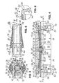
- FIGS. 1 to 4 by way of example, for a place of use for a detachable plug-in connection 10, an intermediate piece is shown, which corresponds to the hydraulically sealed connection of two pipelines 12 in e.g. a hydraulic Kupplungsbetuschists- or brake system for motor vehicles.
- the connector 10 shown in the figures and described in detail below may equally well, for example, at an intermediate piece for hydraulically sealing a pipe with a piece of hose or at a terminal of a hydraulic component, such as a master cylinder or slave cylinder, a pressure modulator for brake systems or other hydraulic brake or clutch actuation units or components are used.
- a pressure modulator for brake systems or other hydraulic brake or clutch actuation units or components are used.
- the connector 10 has a sleeve-like receiving part 14, in which a in Figs. 5 and 6 separately illustrated male member 16 in a joining direction F can be inserted, which is connected to the pipe 12.
- the male part 16 - as in the illustrated embodiment - be integrally formed with the pipe 12.
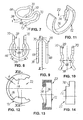
- the connector 10 according to particular FIG. 4 a sealing element 18 sealing between the receiving part 14 and the male 16 and a spring-loaded securing element 20 attached to the receiving part 14, which is shown individually in FIGS Insert 16 to be secured to the receiving part 14 releasably.
- a slotted indicator ring 22 may be provided which is shown separately in Figs. 11 to 14 and provides a visual and / or tactile indication of the connection state of the connector 10 in a manner to be described.
- the insertion part 16 has an abutment 24, with a widening section 26, which continuously widens in the outer diameter opposite to the joining direction F, via which the securing element 20 can be springed when inserting the insertion part 16 into the receiving part 14, and an abutment surface 28, behind which the securing element 20 can be latched at the end of the insertion process and which thus serves to support the insertion part 16 against unintentional release from the receiving part 14 on the securing element 20.
- the widening portion 26 ends opposite to the joining direction F with its largest outer diameter approximately at the abutment surface 28, so that the abutment surface 28 connects substantially seamlessly to the widening portion 26 of the abutment 24.
- a transition section should, however, in the case of eg a securing element 20, which consists of a round spring steel wire, as in the embodiment shown, but not greater than half the diameter of the spring steel wire, in any case to ensure that either the fuse element 20 at the end of the insertion process behind the abutment surface 28 is latched on the male member 16 or, should the male member 16 have not yet been inserted far enough into the female member 14, the male member 16 due to the radially acting spring force of the securing member 20 on the respect to the central axis M of the insertion 16 oblique widening portion 26 against the joining direction F is pushed back out of the receiving part 14 to indicate a not yet done correctly connection between male 16 and receiving part 14.
- the receiving parts 14 of the preferably made of a metallic material, such as steel or an aluminum alloy spacer each have a cylindrical outer peripheral surface 30.
- the cylindrical outer peripheral surfaces 30 are od over a handling portion 32 in the form of a key surface .dgl. connected with each other.
- each cylindrical outer peripheral surface 30 is provided with a radial groove 34 of predetermined width and depth t, which serves to receive the indicator ring 22, as Figs. 1 to 4 illustrate.
- radial groove 34 left end of the radial groove 34 slots 36 are introduced into these diametrically opposite sides of the receiving part, which extend perpendicular to the central axis M.
- the two slots 36 each extend from the groove base of the radial groove 34 into the receiving part 14 and each serve to receive one of two abutment arms 38 of the securing element 20.
- the receiving part 14 further has a connecting bore 40 for receiving the male part 16, which extends from the end face into the intermediate piece. 4, the connection bores 40 of the two receiving parts 14 of the intermediate piece are hydraulically connected to one another via a central throughflow bore 42 in the longitudinal direction of the intermediate piece.
- the connection bore 40 has, starting from the end face of the intermediate piece, three bore sections 44, 46, 48, with a first cylindrical bore section 44, which projects into axial direction extends approximately to the inner end of the radial groove 34, a continuously adjoining thereto, in the joining direction F conically tapered bore portion 46 for centering the male member 16 when joining the connector 10 and a recording of the sealing member 18 serving, second cylindrical bore portion 48, which connects steplessly to the conical bore section 46.
- the diameter of the second cylindrical bore portion 48 is smaller than the diameter of the first cylindrical bore portion 44 but larger than the diameter of the flow bore 42 to define a relatively narrow annulus for receiving the seal member 18. It should be mentioned at this point that the inner diameter of the first cylindrical bore portion 44 is only slightly larger than the largest outer diameter of the conical widening portion 26 of the abutment 24 on the male part 16, while the inner diameter of the second cylindrical bore portion 48 is only slightly larger than the smallest Outer diameter of the expansion portion 26, wherein the expansion portion 26 determines the largest and smallest outer diameter of the abutment 24. As a result, the male member 16 is held in the joined state of the connector 10 with only a very small radial clearance in the connection bore 40 of the receiving part 14.
- FIGS. 5 and 6 show further details of the insertion part 16.
- the insertion part 16 initially has a metallic pipe section 50 which, in the exemplary embodiment shown, is formed in one piece with the pipeline 12 in the same material as the material.
- brake application in motor vehicles is usually a double-walled, internally and externally copper-plated steel tube, which is also provided for corrosion protection reasons on the outer circumference with a galvanized zinc layer on which there is an additional plastic coating.
- On the pipe section 50 which is made of a plastic with a relatively low coefficient of friction, such as polyamide 6.6 - possibly with a predetermined glass fiber content, eg 35% - existing abutment 24 attached.
- the pipe section 50 from the free end of the male member 16 spaced with an upset flange 52 is provided which projects beyond the outer diameter of the other pipe section 50 radially outward and around which the abutment 24 is molded positively, so that the flange 52 of the Widening portion 26 of the abutment 24 is surrounded.
- the sealing surface 56 with the center axis M of the male 16 an angle b smaller than 90 ° and greater than 75 ° include, so that the sealing surface 56 tapers in the joining direction F is substantially conical, whereby the sealing element 18 in the assembled state of the connector 10 is biased by the sealing surface 56 radially outward.
- the respective functional requirements, the sealing surface 56 but also extend perpendicular to the central axis M of the male member 16, as shown on the right in Fig. 4 plug 16.
- the sealing elements 18 shown in FIGS. 4 and 18 to simplify the illustration in the undeformed state are in the exemplary embodiment shown as elastomeric quad rings which, as indicated in FIG. 18, each have an annular body 58, which here has a substantially square shape Cross-section has, as well as four spherical sealing beads 60, which are seen in cross-section in a symmetrical arrangement formed at the corners of the annular body 58. It could also be said that the quadring has a square cross section with rounded corners and a central depression or groove between adjacent rounded corners. According to the respective functional requirements, however, the quadring could also have a different cross-sectional shape, for example having a trapezoidal cross-section.
- the abutment 24 extends with a to the widening portion 26 continuously adjoining cylinder portion 62 to the flange 54 of the pipe section 50 at the free end of the male member 16 out, so that the pipe section 50 of the male part 16 from the abutment 24 to the end-side flange 54 is sheathed protectively.
- the pitch angle a of the widening portion 26 of the abutment 24 is also plotted, that is, the angle ⁇ , which the widening portion 26 encloses with the center axis M of the insertion part 16.
- This may be in the range of 5 ° to 20 °, preferably in the range of 7 ° to 10 °, and is to be matched with the radially acting spring force of the securing element 20.
- the angle a may not be too steep, so that the joining force required for joining the connector 10 keeps within moderate limits.
- the angle a may not be too flat, so that it is ensured that the spring-loaded, at the widening portion 26 of the abutment 24 adjacent fuse element 20, the male member 16 against the joining direction F can push out of the receiving part 14, if the connector 10 was not correctly added to indicate the incorrectly joined state of the connector 10.
- abutment 24 extends with a substantially cylindrical abutment portion 64 for the securing element 20 against the joining direction F on the perpendicular to the central axis M of the male 16 extending, annular abutment surface 28 addition, what else will be discussed in more detail.
- the securing element 20 is shown in more detail, in its rest position, i. in the unloaded condition.
- the securing element 20 is seen in a plan view substantially U-shaped, with the two abutment arms 38 which are resiliently connected to each other via a circular arc portion 66 and mounted in the receiving part 14 state of the securing element 20 through the slots 36th extend into the connection bore 40 of the receiving part 14 in (see Fig. 2 and 3).
- the abutment arms 38 each have a contact portion 68 for the abutment surface 28 of the abutment 24 on the male part 16. While the abutment arms 38 in the side view of FIG.
- FIG. 9 seen in a plane, they have in the plan view of FIG. 8 seen a curved or ., cranked shape, so that they follow in the region of the abutment portions 68 of the circular curvature of the abutment 24 so that they can not punctiform but linear abut the abutment 24.
- the abutment arms 38 of the securing element 20 are connected via bow portions 70 to the arc portion 66, such that the arc portion 66 is substantially parallel extends to the abutment arms 38.
- the arcuate portion 66 as shown in FIGS. 1, 2, 4, 15, 16 and 18 before the opening of the connecting bore 40 in the receiving part 14 is arranged when the abutment arms 38 are positioned in the slots 36 in the receiving part 14.
- the male member 16 is inserted through the arcuate portion 66 of the securing element 20 into the receiving part 14, whereby in the assembled state of the connector 10, the securing element 20 itself or the like on the male part 16 or on the pipe 12. is secured against loss.
- bracket portions 70 of the securing element 20 act as torsion springs whose spring force is superimposed on the spring force acting as a bending spring bow portion 66 and the spring forces of the bending springs acting as abutment arms 38 of the securing element 20 to a spring or spreading the securing element 20 on the abutment portions 68 of the abutment arms 38 to generate radially inwardly directed reaction forces.
- FIG. 3 illustrates that the radial distance of the slots 36 in the receiving part 14 is matched with the clear distance of the abutment arms 38 of the securing element 20, namely such that the securing element 20 is held even when not mated plug 16 on the receiving part 14 to to facilitate the handling of the connector 10.
- FIGS. 11 to 14 show further details of the slotted indicator ring 22, which is preferably injection-molded from a plastic.
- the indicator ring 22 in the plan view according to FIG. 12 has a substantially C-shaped base body 72 whose radial thickness d substantially the depth t of the radial groove 34 in the receiving part 14 corresponds (see Figs. 2 and 4).
- the indicator ring 22 on substantially diametrically opposite sides radially inwardly directed projections 74 which are formed so that they fit into the slots 36 in the receiving part 14. More specifically, according to particular Fig.
- the projections 74 of the indicator ring 22 extend in its mounted on the receiving part 14 state in the slots 36 in the receiving part 14 in order to abut against the abutment arms 38 of the securing element 20, more precisely on the abutment portions 68 outside.
- the main body 72 is provided between the projections 74 with a recess 76 so as not to collide with the strap portions 70 of the securing element 20.
- a disassembly or a release of the connector 10 only by means of a special tool is possible, as it is disclosed for example in US 5,909,901.
- a special tool may in the present case have two projections which are insertable from the end face of the receiving part 14 in the first bore portion 44 of the connection bore 40, seen in the radial direction between the inner peripheral surface of the receiving part 14 and the outer peripheral surface of the abutment portion 64 of the abutment A rotation of this tool from this starting position by 90 ° about the central axis M now causes a radial spreading of the securing element 20 such that the male member 16 together with the tool from can be pulled out of the receiving part 14.
- the correctly or incorrectly joined state of the connector 10 is displayed visually, tactile and audible and acoustically, with a correctly mated connector exists, (i) when the male member 16 is not through the fuse element 20 from (ii) when the indicator ring 22 does not protrude beyond the outer peripheral surface 30 of the receiving part 14 (optical and haptic display), and (iii) when the abutment arms 38 of the securing element 20 behind the same when locking the receiving member 14 (optical and haptic display) the abutment surface 28 on the receiving part 14 with a perceptible Sound ("click") abut the contact portion 64 of the abutment 24 (acoustic indicator).
- a connector for piping with a receiving part, a therein insertable plug-in, sealing between receiving part and male sealing element and a resilient locking element to secure the male part on the receiving part
- the former having a pipe section on which an abutment is provided with a widening portion which enlarges in the outer diameter opposite to the joining direction and over which the securing element can be springed, and an abutment surface behind which the securing element can be latched and which supports the insertion part against unintentional release on the securing element.
- the widening section terminates counter to the joining direction with its largest outer diameter approximately at the abutment surface, wherein on the pipe section a flare is formed which forms an end-face sealing surface against which the sealing element sealingly rests when the plug-in connection is mounted.
Landscapes
- Engineering & Computer Science (AREA)
- General Engineering & Computer Science (AREA)
- Mechanical Engineering (AREA)
- Quick-Acting Or Multi-Walled Pipe Joints (AREA)
Applications Claiming Priority (1)
| Application Number | Priority Date | Filing Date | Title |
|---|---|---|---|
| DE102004044917A DE102004044917A1 (de) | 2004-09-14 | 2004-09-14 | Lösbare Steckverbindung für Rohrleitungen od. dgl. |
Publications (2)
| Publication Number | Publication Date |
|---|---|
| EP1635103A1 true EP1635103A1 (fr) | 2006-03-15 |
| EP1635103B1 EP1635103B1 (fr) | 2007-05-30 |
Family
ID=35427956
Family Applications (1)
| Application Number | Title | Priority Date | Filing Date |
|---|---|---|---|
| EP05017154A Not-in-force EP1635103B1 (fr) | 2004-09-14 | 2005-08-06 | Raccord détachable à fiche pour des tuyaux ou similaires |
Country Status (4)
| Country | Link |
|---|---|
| US (1) | US7631904B2 (fr) |
| EP (1) | EP1635103B1 (fr) |
| DE (2) | DE102004044917A1 (fr) |
| ES (1) | ES2286743T3 (fr) |
Cited By (4)
| Publication number | Priority date | Publication date | Assignee | Title |
|---|---|---|---|---|
| EP2105647A2 (fr) | 2008-03-27 | 2009-09-30 | FTE automotive GmbH | Raccord enfichable amovible pour conduites ou analogues |
| US20140338773A1 (en) * | 2013-05-20 | 2014-11-20 | Steere Enterprises, Inc. | Clean air duct and retaining clip and assembly thereof |
| CN105849453A (zh) * | 2013-12-31 | 2016-08-10 | 萃菲美股份有限公司 | 快速接头装置,含有一个斜切圆空筒和两个内环槽 |
| US10859194B2 (en) | 2013-05-20 | 2020-12-08 | Steere Enterprises, Inc. | Clean air duct and retaining clip and assembly thereof |
Families Citing this family (18)
| Publication number | Priority date | Publication date | Assignee | Title |
|---|---|---|---|---|
| AU2013206009B2 (en) * | 2006-11-09 | 2016-06-16 | Caterpillar Global Mining Expanded Products Pty Ltd | A fastener retaining device |
| FR2929679B1 (fr) * | 2008-04-07 | 2010-04-23 | Raymond A & Cie | Raccord de connecteur pour conduits de fluide avec un ressort en fil metallique |
| BRMU8801923U2 (pt) * | 2008-09-01 | 2010-05-04 | Electrolux Do Brasil Sa | sistema de fixação para tubo de gás em fogões |
| DE102009050675A1 (de) | 2008-11-17 | 2010-05-20 | Luk Lamellen Und Kupplungsbau Beteiligungs Kg | Steckverbindung zum Herstellen einer fluiddichten Verbindung |
| US9273812B2 (en) * | 2009-09-24 | 2016-03-01 | Perfection Clutch | Hydraulic line connector |
| DE102010015496B4 (de) * | 2010-04-16 | 2018-07-12 | Gedore Torque Solutions Gmbh | Gehäuse für ein Hydraulikaggregat |
| EP2597348A1 (fr) * | 2011-11-24 | 2013-05-29 | Eaton Germany GmbH | Connexion raccordable dotée d'une pince de rétention |
| FR2983556B1 (fr) * | 2011-12-06 | 2013-12-13 | Hutchinson | Organe de verrouillage d'un dispositif de raccordement pour transfert de fluide, ce dispositif et son procede de verrouillage. |
| DE102012005930A1 (de) * | 2012-03-26 | 2013-09-26 | Veritas Ag | Steckverbindungsanordnung |
| CA2877961C (fr) * | 2012-07-02 | 2019-09-24 | Norma U.S. Holding Llc | Raccord de conduite de carburant et son procede de fabrication |
| FR2993630B1 (fr) * | 2012-07-23 | 2014-07-11 | Raymond A & Cie | Dispositif de raccordement fluidique avec une bague reductrice d'effort de montage |
| WO2014172370A1 (fr) * | 2013-04-16 | 2014-10-23 | Eaton Corporation | Étrier d'assemblage pour raccord de conduite de fluide |
| KR101519275B1 (ko) | 2013-12-20 | 2015-05-11 | 현대자동차주식회사 | 차량용 유압튜브 |
| DE102016210283A1 (de) | 2016-06-10 | 2017-12-14 | Schaeffler Technologies AG & Co. KG | Leitungssystem für eine fluidische Kupplungsbetätigungseinrichtung mit einer asymmetrischen Drahtformfeder |
| US10550982B2 (en) * | 2016-06-17 | 2020-02-04 | Ti Group Automotive Systems, Llc | Quick connector |
| WO2018102213A1 (fr) * | 2016-12-01 | 2018-06-07 | Illinois Tool Works Inc. | Connecteur rapide ayant une indication de verrouillage positif |
| PL3669110T3 (pl) * | 2017-08-14 | 2022-03-28 | Oetiker Ny, Inc. | Szybkozłącze z wkładką wskaźnikową |
| FR3083290B1 (fr) * | 2018-06-29 | 2021-12-24 | Sogefi Air & Cooling | Systeme de raccordement rapide et procede de realisation |
Citations (7)
| Publication number | Priority date | Publication date | Assignee | Title |
|---|---|---|---|---|
| DE3531926A1 (de) * | 1985-09-07 | 1987-03-19 | Kugelfischer G Schaefer & Co | Loesbare steckverbindung |
| DE9014400U1 (de) * | 1990-10-17 | 1990-12-20 | Armaturenfabrik Hermann Voss GmbH + Co, 5272 Wipperfürth | Steckverbindung für flexible Leitungen |
| DE4236323A1 (de) * | 1992-10-28 | 1994-05-05 | Teves Gmbh Alfred | Einrastbarer Anschluß einer starren Druckmittelleitung |
| DE29610434U1 (de) | 1996-06-14 | 1996-08-22 | Fahrzeugtechnik Ebern Gmbh, 96106 Ebern | Ausbildung eines Endstücks eines Hydraulikrohrs für eine lösbare Steckverbindung |
| EP0811798A2 (fr) * | 1996-06-07 | 1997-12-10 | Cohnen Beteiligungs-GmbH & Co. KG | Raccord rapide |
| US5909901A (en) | 1998-02-22 | 1999-06-08 | Jiffy-Tite Company, Inc. | Disconnect tool for a fluid line quick-connect assembly |
| US20030052484A1 (en) * | 2001-02-05 | 2003-03-20 | Stephane Rautureau | Supply connection device for a fluid pressure system |
Family Cites Families (9)
| Publication number | Priority date | Publication date | Assignee | Title |
|---|---|---|---|---|
| US2873132A (en) * | 1954-04-23 | 1959-02-10 | Tanner Engineering Co | Fluid pressure seal ring |
| US3428340A (en) * | 1967-03-20 | 1969-02-18 | Harry L Pelton | Hose coupling |
| US3628768A (en) * | 1970-10-16 | 1971-12-21 | Primore Sales Inc | Quick connecting coupling |
| US4524995A (en) * | 1980-10-29 | 1985-06-25 | Proprietary Technology, Inc. | Swivelable quick connector assembly |
| US4423891A (en) * | 1981-09-28 | 1984-01-03 | Menges William H | Corrugated hose coupling |
| US5120085A (en) * | 1989-09-28 | 1992-06-09 | Sang Man Shin | Pipe connecting device |
| US5538297A (en) * | 1991-09-10 | 1996-07-23 | Bundy Corporation | Quick connect tubing connector |
| JP3187549B2 (ja) * | 1991-09-18 | 2001-07-11 | 東海ゴム工業株式会社 | コネクタ及び雄コネクタ |
| DE19822753A1 (de) * | 1998-05-20 | 1999-12-02 | Veritas Gummiwerke Ag | Rohrleitung |
-
2004
- 2004-09-14 DE DE102004044917A patent/DE102004044917A1/de not_active Withdrawn
-
2005
- 2005-08-06 EP EP05017154A patent/EP1635103B1/fr not_active Not-in-force
- 2005-08-06 ES ES05017154T patent/ES2286743T3/es active Active
- 2005-08-06 DE DE502005000773T patent/DE502005000773D1/de active Active
- 2005-09-12 US US11/224,396 patent/US7631904B2/en not_active Expired - Fee Related
Patent Citations (9)
| Publication number | Priority date | Publication date | Assignee | Title |
|---|---|---|---|---|
| DE3531926A1 (de) * | 1985-09-07 | 1987-03-19 | Kugelfischer G Schaefer & Co | Loesbare steckverbindung |
| DE3531926C2 (fr) | 1985-09-07 | 1988-07-14 | Fag Kugelfischer Georg Schaefer Kgaa, 8720 Schweinfurt, De | |
| DE9014400U1 (de) * | 1990-10-17 | 1990-12-20 | Armaturenfabrik Hermann Voss GmbH + Co, 5272 Wipperfürth | Steckverbindung für flexible Leitungen |
| DE4236323A1 (de) * | 1992-10-28 | 1994-05-05 | Teves Gmbh Alfred | Einrastbarer Anschluß einer starren Druckmittelleitung |
| EP0811798A2 (fr) * | 1996-06-07 | 1997-12-10 | Cohnen Beteiligungs-GmbH & Co. KG | Raccord rapide |
| DE29610434U1 (de) | 1996-06-14 | 1996-08-22 | Fahrzeugtechnik Ebern Gmbh, 96106 Ebern | Ausbildung eines Endstücks eines Hydraulikrohrs für eine lösbare Steckverbindung |
| US5909901A (en) | 1998-02-22 | 1999-06-08 | Jiffy-Tite Company, Inc. | Disconnect tool for a fluid line quick-connect assembly |
| US20030052484A1 (en) * | 2001-02-05 | 2003-03-20 | Stephane Rautureau | Supply connection device for a fluid pressure system |
| DE10290508T1 (de) | 2001-02-05 | 2003-12-24 | Valeo | Zuleitungsanschlußvorrichtung für ein Fluiddrucksystem |
Cited By (6)
| Publication number | Priority date | Publication date | Assignee | Title |
|---|---|---|---|---|
| EP2105647A2 (fr) | 2008-03-27 | 2009-09-30 | FTE automotive GmbH | Raccord enfichable amovible pour conduites ou analogues |
| DE102008015811A1 (de) | 2008-03-27 | 2009-10-01 | Fte Automotive Gmbh | Lösbare Steckverbindung für Rohrleitungen od. dgl. |
| US20140338773A1 (en) * | 2013-05-20 | 2014-11-20 | Steere Enterprises, Inc. | Clean air duct and retaining clip and assembly thereof |
| US9664321B2 (en) * | 2013-05-20 | 2017-05-30 | Steere Enterprises, Inc. | Clean air duct and retaining clip and assembly thereof |
| US10859194B2 (en) | 2013-05-20 | 2020-12-08 | Steere Enterprises, Inc. | Clean air duct and retaining clip and assembly thereof |
| CN105849453A (zh) * | 2013-12-31 | 2016-08-10 | 萃菲美股份有限公司 | 快速接头装置,含有一个斜切圆空筒和两个内环槽 |
Also Published As
| Publication number | Publication date |
|---|---|
| EP1635103B1 (fr) | 2007-05-30 |
| DE502005000773D1 (de) | 2007-07-12 |
| DE102004044917A1 (de) | 2006-03-16 |
| US20060082146A1 (en) | 2006-04-20 |
| ES2286743T3 (es) | 2007-12-01 |
| US7631904B2 (en) | 2009-12-15 |
Similar Documents
| Publication | Publication Date | Title |
|---|---|---|
| EP1635103B1 (fr) | Raccord détachable à fiche pour des tuyaux ou similaires | |
| EP3121501B1 (fr) | Vehicule automobile avec composant de vehicule | |
| EP2730828B1 (fr) | Dispositif de raccord fileté pour conduites tubulaires, en particulier pour conduites tubulaires de véhicules automobiles | |
| DE10234615B4 (de) | Bördelverbindungsbaugruppe für Klimatisierungsanlagen von Kraftfahrzeugen | |
| EP2404097B1 (fr) | Système de raccord pour le raccord d'un tuyau à un tuyau principal | |
| EP2008011B1 (fr) | Connecteur pour conduites constituees en particulier de plastique | |
| DE102016223355A1 (de) | Verbindungsvorrichtung | |
| EP1770320B1 (fr) | Raccord détachable à fiche pour des tuyaux | |
| EP2669561A1 (fr) | Dispositif de liaison de conduits | |
| DE202007010592U1 (de) | Anordnung zur Befestigung einer Leitung mit einem profilierten Außendurchmesser | |
| EP1857724B1 (fr) | Raccord de tuyau avec tuyau déformé | |
| DE102020102277A1 (de) | Anschlussarmatur für eine Ventil- und/oder Messkupplung für fluidische Systeme zur Erfassung von Fluiddrücken sowie zur Befüllung, Entleerung und Entlüftung fluidischer Systeme | |
| DE60119577T2 (de) | Schnellkupplung mit drehverrieglung für hochdruck | |
| DE3739626A1 (de) | Steckverbindung | |
| DE102012000602A1 (de) | Gelenkeinheit eines Kraftfahrzeugs und Verfahren zu deren Herstellung | |
| DE102011053208A1 (de) | Verbindungsanordnung für Fluidleitungen mit einer weiteren fluidführenden Komponente | |
| EP0306770B1 (fr) | Liaison mécanique pour tuyaux à air comprimé en matière plastique | |
| DE102005006798A1 (de) | Verbindungsanordnung | |
| DE202021102672U1 (de) | Kompakter Klemmverbinder für Rohre | |
| DE102010012523A1 (de) | Vorrichtung zum Verbinden mit einer Rohr- oder Schlauchleitung, insbesondere Klemmringverschraubung | |
| EP1462702B1 (fr) | Raccord de tuyaux avec un tuyau déformé | |
| EP3153757B1 (fr) | Raccord déconnectable | |
| DE102009053388A1 (de) | Ventil mit Demotageschutz sowie Montagehilfe | |
| DE102008016015B3 (de) | Vorrichtung zum Verbinden einer Druckmittelleitung mit einem Druckmittelaggregat | |
| EP1746329B1 (fr) | Connecteur enfichable |
Legal Events
| Date | Code | Title | Description |
|---|---|---|---|
| PUAI | Public reference made under article 153(3) epc to a published international application that has entered the european phase |
Free format text: ORIGINAL CODE: 0009012 |
|
| AK | Designated contracting states |
Kind code of ref document: A1 Designated state(s): AT BE BG CH CY CZ DE DK EE ES FI FR GB GR HU IE IS IT LI LT LU LV MC NL PL PT RO SE SI SK TR |
|
| AX | Request for extension of the european patent |
Extension state: AL BA HR MK YU |
|
| 17P | Request for examination filed |
Effective date: 20060121 |
|
| GRAP | Despatch of communication of intention to grant a patent |
Free format text: ORIGINAL CODE: EPIDOSNIGR1 |
|
| GRAS | Grant fee paid |
Free format text: ORIGINAL CODE: EPIDOSNIGR3 |
|
| AKX | Designation fees paid |
Designated state(s): DE ES FR GB IT |
|
| GRAA | (expected) grant |
Free format text: ORIGINAL CODE: 0009210 |
|
| AK | Designated contracting states |
Kind code of ref document: B1 Designated state(s): DE ES FR GB IT |
|
| REG | Reference to a national code |
Ref country code: GB Ref legal event code: FG4D Free format text: NOT ENGLISH |
|
| GBT | Gb: translation of ep patent filed (gb section 77(6)(a)/1977) |
Effective date: 20070614 |
|
| REF | Corresponds to: |
Ref document number: 502005000773 Country of ref document: DE Date of ref document: 20070712 Kind code of ref document: P |
|
| ET | Fr: translation filed | ||
| REG | Reference to a national code |
Ref country code: ES Ref legal event code: FG2A Ref document number: 2286743 Country of ref document: ES Kind code of ref document: T3 |
|
| PLBE | No opposition filed within time limit |
Free format text: ORIGINAL CODE: 0009261 |
|
| STAA | Information on the status of an ep patent application or granted ep patent |
Free format text: STATUS: NO OPPOSITION FILED WITHIN TIME LIMIT |
|
| 26N | No opposition filed |
Effective date: 20080303 |
|
| REG | Reference to a national code |
Ref country code: FR Ref legal event code: PLFP Year of fee payment: 12 |
|
| REG | Reference to a national code |
Ref country code: FR Ref legal event code: PLFP Year of fee payment: 13 |
|
| PGFP | Annual fee paid to national office [announced via postgrant information from national office to epo] |
Ref country code: GB Payment date: 20170929 Year of fee payment: 13 |
|
| REG | Reference to a national code |
Ref country code: FR Ref legal event code: PLFP Year of fee payment: 14 |
|
| GBPC | Gb: european patent ceased through non-payment of renewal fee |
Effective date: 20180806 |
|
| PG25 | Lapsed in a contracting state [announced via postgrant information from national office to epo] |
Ref country code: IT Free format text: LAPSE BECAUSE OF NON-PAYMENT OF DUE FEES Effective date: 20180806 |
|
| REG | Reference to a national code |
Ref country code: ES Ref legal event code: FD2A Effective date: 20190918 |
|
| PG25 | Lapsed in a contracting state [announced via postgrant information from national office to epo] |
Ref country code: GB Free format text: LAPSE BECAUSE OF NON-PAYMENT OF DUE FEES Effective date: 20180806 Ref country code: ES Free format text: LAPSE BECAUSE OF NON-PAYMENT OF DUE FEES Effective date: 20180807 |
|
| PGFP | Annual fee paid to national office [announced via postgrant information from national office to epo] |
Ref country code: FR Payment date: 20200831 Year of fee payment: 16 Ref country code: DE Payment date: 20200806 Year of fee payment: 16 |
|
| REG | Reference to a national code |
Ref country code: DE Ref legal event code: R119 Ref document number: 502005000773 Country of ref document: DE |
|
| PG25 | Lapsed in a contracting state [announced via postgrant information from national office to epo] |
Ref country code: FR Free format text: LAPSE BECAUSE OF NON-PAYMENT OF DUE FEES Effective date: 20210831 Ref country code: DE Free format text: LAPSE BECAUSE OF NON-PAYMENT OF DUE FEES Effective date: 20220301 |