EP1634680A1 - Vacuum clamping detection method and vacuum clamping detector - Google Patents
Vacuum clamping detection method and vacuum clamping detector Download PDFInfo
- Publication number
- EP1634680A1 EP1634680A1 EP04734951A EP04734951A EP1634680A1 EP 1634680 A1 EP1634680 A1 EP 1634680A1 EP 04734951 A EP04734951 A EP 04734951A EP 04734951 A EP04734951 A EP 04734951A EP 1634680 A1 EP1634680 A1 EP 1634680A1
- Authority
- EP
- European Patent Office
- Prior art keywords
- suction
- pressure
- drop
- detection
- workpiece
- Prior art date
- Legal status (The legal status is an assumption and is not a legal conclusion. Google has not performed a legal analysis and makes no representation as to the accuracy of the status listed.)
- Withdrawn
Links
Images




Classifications
-
- H—ELECTRICITY
- H05—ELECTRIC TECHNIQUES NOT OTHERWISE PROVIDED FOR
- H05K—PRINTED CIRCUITS; CASINGS OR CONSTRUCTIONAL DETAILS OF ELECTRIC APPARATUS; MANUFACTURE OF ASSEMBLAGES OF ELECTRICAL COMPONENTS
- H05K13/00—Apparatus or processes specially adapted for manufacturing or adjusting assemblages of electric components
- H05K13/04—Mounting of components, e.g. of leadless components
- H05K13/0404—Pick-and-place heads or apparatus, e.g. with jaws
- H05K13/0413—Pick-and-place heads or apparatus, e.g. with jaws with orientation of the component while holding it; Drive mechanisms for gripping tools, e.g. lifting, lowering or turning of gripping tools
-
- B—PERFORMING OPERATIONS; TRANSPORTING
- B25—HAND TOOLS; PORTABLE POWER-DRIVEN TOOLS; MANIPULATORS
- B25J—MANIPULATORS; CHAMBERS PROVIDED WITH MANIPULATION DEVICES
- B25J15/00—Gripping heads and other end effectors
- B25J15/06—Gripping heads and other end effectors with vacuum or magnetic holding means
- B25J15/0616—Gripping heads and other end effectors with vacuum or magnetic holding means with vacuum
-
- B—PERFORMING OPERATIONS; TRANSPORTING
- B65—CONVEYING; PACKING; STORING; HANDLING THIN OR FILAMENTARY MATERIAL
- B65G—TRANSPORT OR STORAGE DEVICES, e.g. CONVEYORS FOR LOADING OR TIPPING, SHOP CONVEYOR SYSTEMS OR PNEUMATIC TUBE CONVEYORS
- B65G47/00—Article or material-handling devices associated with conveyors; Methods employing such devices
- B65G47/74—Feeding, transfer, or discharging devices of particular kinds or types
- B65G47/90—Devices for picking-up and depositing articles or materials
- B65G47/91—Devices for picking-up and depositing articles or materials incorporating pneumatic, e.g. suction, grippers
- B65G47/917—Devices for picking-up and depositing articles or materials incorporating pneumatic, e.g. suction, grippers control arrangements
-
- H—ELECTRICITY
- H05—ELECTRIC TECHNIQUES NOT OTHERWISE PROVIDED FOR
- H05K—PRINTED CIRCUITS; CASINGS OR CONSTRUCTIONAL DETAILS OF ELECTRIC APPARATUS; MANUFACTURE OF ASSEMBLAGES OF ELECTRICAL COMPONENTS
- H05K13/00—Apparatus or processes specially adapted for manufacturing or adjusting assemblages of electric components
- H05K13/08—Monitoring manufacture of assemblages
- H05K13/081—Integration of optical monitoring devices in assembly lines; Processes using optical monitoring devices specially adapted for controlling devices or machines in assembly lines
- H05K13/0815—Controlling of component placement on the substrate during or after manufacturing
-
- H—ELECTRICITY
- H05—ELECTRIC TECHNIQUES NOT OTHERWISE PROVIDED FOR
- H05K—PRINTED CIRCUITS; CASINGS OR CONSTRUCTIONAL DETAILS OF ELECTRIC APPARATUS; MANUFACTURE OF ASSEMBLAGES OF ELECTRICAL COMPONENTS
- H05K13/00—Apparatus or processes specially adapted for manufacturing or adjusting assemblages of electric components
- H05K13/08—Monitoring manufacture of assemblages
- H05K13/082—Integration of non-optical monitoring devices, i.e. using non-optical inspection means, e.g. electrical means, mechanical means or X-rays
-
- H—ELECTRICITY
- H10—SEMICONDUCTOR DEVICES; ELECTRIC SOLID-STATE DEVICES NOT OTHERWISE PROVIDED FOR
- H10P—GENERIC PROCESSES OR APPARATUS FOR THE MANUFACTURE OR TREATMENT OF DEVICES COVERED BY CLASS H10
- H10P72/00—Handling or holding of wafers, substrates or devices during manufacture or treatment thereof
- H10P72/70—Handling or holding of wafers, substrates or devices during manufacture or treatment thereof for supporting or gripping
- H10P72/78—Handling or holding of wafers, substrates or devices during manufacture or treatment thereof for supporting or gripping using vacuum or suction, e.g. Bernoulli chucks
-
- Y—GENERAL TAGGING OF NEW TECHNOLOGICAL DEVELOPMENTS; GENERAL TAGGING OF CROSS-SECTIONAL TECHNOLOGIES SPANNING OVER SEVERAL SECTIONS OF THE IPC; TECHNICAL SUBJECTS COVERED BY FORMER USPC CROSS-REFERENCE ART COLLECTIONS [XRACs] AND DIGESTS
- Y10—TECHNICAL SUBJECTS COVERED BY FORMER USPC
- Y10T—TECHNICAL SUBJECTS COVERED BY FORMER US CLASSIFICATION
- Y10T29/00—Metal working
- Y10T29/53—Means to assemble or disassemble
- Y10T29/5313—Means to assemble electrical device
- Y10T29/53174—Means to fasten electrical component to wiring board, base, or substrate
- Y10T29/53178—Chip component
Definitions
- the present invention relates to a suction detection method and a suction detection apparatus for detecting suction of a workpiece, the suction detection method and apparatus being effectively used for a vacuum-suction/transfer apparatus for transferring, as a workpiece, an electronic component such as IC and LSI to a test instrument, a printed circuit board or the like by vacuum suction.
- a horizontally movable carrying head is provided with a sucker to be movable vertically; and the carrying head is moved to predetermined positions of a component supply stage and the test instrument; and the sucker is moved vertically at each predetermined position of the component supply stage and the test instrument.
- a suction/release passage which is connected to a positive pressure source and a negative pressure source and opened to a contact face that contacts with the workpiece, is formed in the sucker so that, on the component supply stage, negative pressure is supplied to the suction/release passage and the sucker is brought into contact with the workpiece to suck the workpiece.
- the supply of the negative pressure to the suction/release passage is stopped to place the workpiece on the test instrument and positive pressure air for vacuum breakage is supplied to the suction/release passage so that the workpiece can be securely released from the sucker. Then, the carrying head, which has released the workpiece, returns to the component supply stage, and the transfer of the workpieces is repeated in the same procedure.
- a suction/transfer apparatus In such a suction/transfer apparatus, the transfer operation is performed after confirming that the workpiece has been sucked by the sucker in order to prevent missing or dropping of the workpiece during the transfer.
- a conventional suction/transfer apparatus has a suction pressure sensor for detecting pressure in the suction/release passage, which detects the suction of the workpiece when a negative pressure value in the suction/release passage increases to or beyond its suction detection value during a suction operation.
- the suction/transfer apparatus can recognize the drop of the workpiece even during the transfer.
- the release of the workpiece from the sucker is detected only when the negative pressure value of the suction/release passage is equal to or less than a release pressure value Preset set at negative pressure lower than the suction preparation pressure Pset. Therefore, even if the workpiece drops during the transfer and the sucker becomes in a state of sucking nothing, the negative pressure value of the suction/release passage is not reduced below the suction preparation pressure Pset, so that the drop of the workpiece cannot be recognized during the transfer.
- An object of the present invention is to be capable of securely detecting the drop of the workpiece from the sucker when the workpiece is transferred by the sucker.
- a suction detection method is a method for making a detection of whether a workpiece is sucked by a sucker having a suction/release passage connected to a negative pressure passage, and comprises: a reference pressure reading step of reading, as reference pressure, pressure in said suction/release passage under the condition that the workpiece is sucked by said sucker; a drop-detection range setting step of setting a drop detection range by adding predetermined allowable deflection width (tolerance) to said reference pressure; a drop-detection pressure reading step of reading, as drop detection pressure, the pressure in said suction/release passage; a recognizing step of recognizing whether said drop detection pressure is equal to or more than an upper limit value of said drop detection range; and a drop-signal outputting step of outputting a drop signal when it is recognized that said drop detection pressure is equal to or more than said upper limit value.
- the suction detection method according to claim the present invention further comprises a rewriting step of being rewritten to a new drop detection range when said reference pressure is different from the previous reference pressure.
- the suction detection method according to the present invention is such that, by reading said reference pressure based on a reference-pressure reading instruction and then reading said drop detection pressure based on a drop-detection pressure reading instruction, it is recognized whether said drop detection pressure is equal to or more than an upper limit value of said drop detection range.
- a suction detection apparatus is an apparatus to detect whether a workpiece is sucked by a sucker having a suction/release passage connected to a negative pressure source, and comprises: a reference pressure reading means for reading, as reference pressure, pressure in said suction/release passage under the condition that the workpiece is sucked by said sucker; a drop-detection range setting means for setting a drop detection range by adding predetermined allowable deflection width to said reference pressure; a drop-detection pressure reading means for reading, as drop detection pressure, the pressure in said suction/release passage; a recognizing means for recognizing whether said drop detection pressure is equal to or more than an upper limit value of said drop detection range; and a drop-signal outputting means for outputting a drop signal when it is recognized that said drop detection pressure is equal to or more than said upper limit value.
- the suction detection apparatus is such that the drop detection range is newly rewritten if said reference pressure is different from the previous reference pressure.
- the suction detection method according to the present invention is such that by reading said reference pressure based on a reference-pressure reading instruction and then reading said drop detection pressure based on a drop-detection pressure reading instruction, it is recognized whether said drop detection pressure is equal to or more than the upper limit value of said drop detection range.
- the suction of the workpiece by the sucker can be securely detected also during the transfer of the workpiece.
- the timing of the drop recognition for the suction detection apparatus can be changed freely.
- FIGs. 1A to 1E are explanatory diagrams showing a transfer procedure for sucking and transferring a workpiece by a vacuum-suction/transfer apparatus equipped with a suction detection apparatus according to an embodiment of the present invention
- FIG. 2 is a block diagram showing schematically the vacuum-suction/transfer apparatus shown in FIG. 1.
- this vacuum-suction/transfer apparatus 11 transfers, as workpieces W, electronic components such as ICs disposed on a component supply stage 12 to a printed circuit board 14 by sucking them using a sucker 13.
- This vacuum-suction/transfer apparatus 11 has a horizontally movable carrying head 15, so that the carrying head 15 can be driven horizontally between the component supply stage 12 and the printed circuit board 14 by an unshown electronic motor etc.
- a pneumatic cylinder 16 is fixed to the carrying head 15, and a piston rod 17 is attached to this pneumatic cylinder 16 so as to be reciprocable vertically.
- a positive pressure source 19 is connected to the pneumatic cylinder 16 through an electromagnetic valve 18. When no current flows in the electromagnetic valve 18, the piston rod 17 is retained at its retraction limit position. If a current flows in the electromagnetic valve 18, the piston rod 17 advances downward in these Figures due to compressed air supplied from the positive pressure source 19. Then, the sucker 13 is attached to a tip of the piston rod 17.
- the sucker 13 is also called a suction gripper or vacuum gripper and, as shown in FIG. 2, has a hollow space in which an air-flow passage 20 is formed.
- This air-flow passage 20 is provided at a tip of the sucker 13 and is opened to a contact face 21 that contacts with the workpiece W, and a tip portion of the air-flow passage 20 serves as a vacuum suction port 22.
- the vacuum supply valve 23 is an electromagnetic valve which opens/closes a flow passage by current-carrying control with respect to a solenoid 23a, so that when a current flows in the solenoid 23a, the vacuum supply valve is set to an open position for communicating the suction/release passage 28 with the negative pressure source 24 and if flow of the current into the solenoid 23a is interrupted, it is set to a close position for closing the suction/release passage 28.
- the vacuum breakage valve 25 is similarly an electromagnetic valve which opens/closes a flow passage by the current-carrying control with respect to a solenoid 25a, so that when the current flows in the solenoid 25a, the vacuum breakage valve is set to an open position for communicating the suction/release passage 28 with the positive pressure source 26 and if the flow of the current into the solenoid 25a is interrupted, it is set to a close position for closing the suction/release passage 28.
- This vacuum breakage valve 25 is provided with a variable throttle 29 for adjusting a flow rate of compressed air.
- the vacuum-suction/transfer apparatus 11 is provided with an apparatus controller 30, which includes an unshown micro processor for computing various kinds of control signals, and unshown memories such as a ROM for storing control program, operational expressions, and data table, etc. and a RAM for storing temporary data.
- An unshown electric motor for driving the electromagnetic valve 18 and the above-mentioned pneumatic cylinder 16, the solenoids 23a, 25a of the respective valves 23, 25, and the carrying head 15 is connected to the apparatus controller 30, so that operations of these members are controlled by the apparatus controller 30.
- a suction pressure sensor 31 is connected to the suction/release passage 28, thereby making it possible to detect suction/release-passage-internal pressure Pin.
- Detected pressure value of the suction pressure sensor 31 is gauge pressure in which atmospheric pressure is used as a reference, and even when the suction/release passage 28 is connected to either the negative pressure source 24 or the positive pressure source 26, the suction/release-passage-internal pressure Pin can be detected.
- the suction/pressure sensor 31 is separated from a suction detection apparatus 32, and these are connected through a communication cable 33. And, the detected suction/release-passage-internal pressure Pin is inputted as a voltage or current signal to the suction detection apparatus 32.
- the suction detection apparatus 32 is connected respectively to the suction pressure sensor 31 and the apparatus controller 30 through communication cables 33, 34, and has an unshown micro processor computing various kinds of control signals and an unshown memory including a ROM and a RAM, etc. similarly to the apparatus controller 30.
- Various kinds of values such as suction detection pressure value Pj, a suction detection value ⁇ Pset, a release pressure value Preset, an unreachable value Pu, and allowable deflection width ⁇ D, etc. are stored in the memory. These values can be changed by operating an unshown key or dial provided on the suction/detection apparatus 32 or by sending a signal from the apparatus controller 30.
- the unreachable value Pu is set at such high a negative pressure value that suction preparation pressure Pset cannot reach even if various conditions change, for example, an inner diameter of the suction/release passage 28 decreases.
- the unreachable value Pu is set at - 101.3 kPa which is an absolute vacuum under the gauge pressure.
- the suction/detection apparatus 32 can recognize whether the suction/release-passage-internal pressure Pin is positive pressure or negative pressure and, in order to detect the suction of the workpiece W, reads the suction preparation pressure Pset and adds a predetermined suction detection value ⁇ Pset to this value to set the suction detection pressure Pj. After the transfer is started, the suction/release-passage-internal pressure Pin is read as reference pressure Ps and the predetermined allowable deflection width ⁇ D is added to the above internal pressure Pin to set a drop detection range. At the same time, during the transfer of the workpiece W, the drop of the workpiece W is detected after receiving an instruction from the apparatus controller 30.
- a release pressure value Preset when a release pressure value Preset is detected, the release of the workpiece W is detected and an output of a suction confirmation signal ("A" signal) is stopped. If the release of the workpiece W from the sucker 13 is detected, the suction detection pressure Pj is set at the predetermined unreachable value Pu.
- suction confirmation of the workpiece W and a result of its drop recognition are sent, as a suction confirmation signal ("A" signal) or a drop signal (“E” signal), from the suction/detection apparatus 32 to the apparatus controller 30.
- the carrying head 15 is moved onto the component supply stage 12 after the piston rod 17 ascends.
- the vacuum supply valve 23 is opened to supply the negative pressure to the suction/release passage 28, and the negative pressure value of the suction/release passage 28 rises to the suction preparation pressure Pset.
- the compressed air is supplied to the pneumatic cylinder 16 and the piston rod 17 descends, and since the contact face 21 of the sucker 13 contacts with the workpiece W, the workpiece W is sucked by the sucker 13 due to the negative pressure.
- the carrying head 15 is moved horizontally toward the printed circuit board 14, as shown in FIG. 1C. Then, after the carrying head 15 moves to a predetermined position of the printed circuit board 14, as shown in FIG. 1D, the piston rod 17 descends, whereby the workpiece W is disposed on the printed circuit board 14. In this way, the workpieces W are transferred to the printed circuit board 14 from the component supply stage 12.
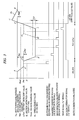
- FIG. 3 is a time chart showing a change in pressure in the suction/release passage detected by a suction pressure sensor when the sucker sucks and transfers the workpiece to the printed circuit board from the component supply stage.
- the suction/release-passage-internal pressure Pin lowers and reaches a point D and the workpiece W is sucked by the sucker 13.
- the transfer of the workpiece W is started after the workpiece W is sucked by the sucker 13, that is, after the apparatus controller 30 receives a suction confirmation signal ("A" signal) from the suction/detection apparatus 32. If the transfer of the workpiece W is completed and the workpiece W is disposed at a predetermined position, the vacuum supply valve 23 is set to the closed position at a point E to stop the supply of the negative pressure. Concurrently, the vacuum breakage valve 25 is set to the open position to supply the positive pressure to the suction/release passage 28, so that the negative pressure lowers and the workpiece W is separated from the sucker 13.
- A suction confirmation signal
- the suction/release-passage-internal pressure Pin rises to the atmospheric pressure at a point F due to the supply of the positive pressure, and further the suction/release-passage-internal pressure Pin rises to a point G set at pressure of the compressed air supplied from the positive pressure source 26. Thereafter, when the vacuum breakage valve 25 is set to the closed position at a point G, the suction/release-passage-internal pressure Pin lowers to the atmospheric pressure and reaches a point H.
- the drop of the workpiece W from the sucker 13 occurs in some cases.
- a cause for the drop of the workpiece W during the transfer for example, an influence of vibrations during the transfer is conceivable.
- the sucker 13 becomes in a state of sucking nothing, so that the negative pressure value of the suction/release passage 28 is reduced to the suction preparation pressure Pset.
- a pressure curve shown by a dot and dash line in FIG. 3 represents a change in the suction/release-passage-internal pressure Pin when the workpiece W drops during the transfer of the workpiece W.
- the drop recognition of the workpiece W during the transfer is carried out by making the detection of whether the negative pressure value of the suction/release passage 28 has changed beyond the predetermined allowable deflection width ⁇ D.
- the reason why the predetermined allowable deflection width ⁇ D is preliminarily set is that the negative pressure value of the suction/release passage 28 is not always stabilized due to friction of flow passage, leakage or the like in use.
- the drop recognition is carried out, by whether a difference between the reference pressure Ps which is the suction/release-passage-internal pressure at a time of confirming the suction and the drop detection pressure Pt detected is within a range of the predetermined allowable deflection width ⁇ D.
- FIG. 4 is a flow chart showing an operation procedure of the sucker when the workpiece is sucked and transferred.
- the operation procedure of the sucker 13 and a suction detection method of the workpiece W will be described with reference to FIGs. 3 and 4.
- the vacuum supply valve 23 is set at the open position and the negative pressure air is supplied to the suction/release passage 28 (step S1). After the supply of the negative pressure air is started, a predetermined period of time elapses and the suction/release-passage-internal pressure Pin passes the point B and is stabilized. At this time, if a suction-preparation pressure reading instruction (Pset signal) is outputted from the apparatus controller 30, reading of the suction preparation pressure Pset is carried out by the suction/detection apparatus 32 in step S2.
- Pset signal a suction-preparation pressure reading instruction
- a suction detection-pressure setting step in the vacuum-suction/transfer apparatus 11 each time the suction preparation pressure Pset is detected, a new suction detection pressure Pj is set by adding the suction detection value ⁇ Pset to this suction preparation pressure Pset, so that the suction detection pressure Pj in the memory is rewritten to the new suction detection pressure Pj on each suction.
- Step S5 is a suction detection step, so that if it is recognized that the suction/release-passage-internal pressure Pin is equal to or less than the suction detection pressure Pj, i.e., "Pin ⁇ Pj" by comparing the suction/release-passage-internal pressure Pin with the suction detection pressure Pj, the suction of the workpiece W is detected and a suction confirmation signal ("A" signal) is outputted from the suction/detection apparatus 32 in Step S6. Then, after the apparatus controller 30 receives the suction confirmation signal ("A" signal), the transfer operation is started in Step S7 and the workpiece W is transferred in a state of being sucked by the sucker 13.
- the reference pressure Ps and the drop detection pressure Pt are required to have been read for comparison in the suction/detection apparatus 32.
- the reference pressure Ps is read by using the suction pressure sensor 31 when the suction/detection apparatus 32 receives a reference pressure reading instruction (Ps signal) under the condition that the workpiece W has been sucked.
- the drop detection pressure Pt is read by using the suction pressure sensor 31 when the suction/detection apparatus 32 receives a drop-detection pressure reading instruction (Pt signal).
- the reference pressure reading instruction (Ps signal) and the drop-detection pressure reading instruction (Pt signal) can be sent at arbitrary timing by operating the apparatus controller 30.
- step S8 If the suction/detection apparatus 32 receives the reference pressure reading instruction (Ps signal) in step S8, the suction/release-passage-internal pressure Pin of the suction/release passage 28 at a time of receiving the signal is detected and is stored in the memory of the suction/detection apparatus 32 (step S9). Unless the reference pressure reading instruction (Ps signal) is received, this operation procedure proceeds to step S10 as branched by the step S8, i.e., so that step S9 is omitted.
- Ps signal the reference pressure reading instruction
- step S10 If the suction/detection apparatus 32 receives the drop-detection pressure reading instruction (Pt signal) in step S10, the suction/release-passage-internal pressure Pin of the suction/release passage 28 at a time of receiving the signal is detected and is stored in the memory of the suction/detection apparatus 32 (step S11).
- step S12 subtraction of the reference pressure Ps from the drop detection pressure Pt is carried out, and whether such a result of the subtraction is within the allowable deflection width ⁇ D is recognized. Note that this recognition is omitted unless the drop-detection pressure reading instruction (Pt signal) is received in the step S10.
- a drop signal (“E" signal) is outputted from the suction/detection apparatus 32 (step S13). Meanwhile, if the drop of the workpiece W is not detected and the completion of the transfer of the workpiece W is confirmed in step S14, the vacuum supply valve 23 is set to the open position and the vacuum breakage valve 25 is set to the closed position, so that the positive pressure is supplied to the suction/release passage 28 (step S15).
- the suction/release-passage-internal pressure Pin rises and the suction/release-passage-internal pressure Pin reaches at a release pressure value Preset, namely, "Pin ⁇ Preset" is detected in step 16
- the release of the workpiece W is detected and the suction confirmation signal ("A" signal) is turned OFF in step S17.
- the value of suction detection pressure Pj in the memory of the suction/detection apparatus 32 is rewritten to the unreachable value Pu in step S18.
- the carrying head 15 is again moved to the component supply stage 12 and the routine is returned to the step S1.
- the suction detection pressure Pj is maintained at the unreachable value Pu until the suction detection pressure Pj is set again in the step S3 via the steps S1, S2.
- the vacuum-suction/transfer apparatus includes an apparatus in which, in order to transfer the plurality of workpieces W all at once, the plurality of suckers 13 each provided with an opening/closing valve 35 are connected to the common negative pressure source 24 through a common suction unit 36.
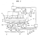
- FIG. 5 is a block diagram showing schematically the vacuum-suction/transfer apparatus connecting the plurality of suckers to a common negative pressure source by using the suction unit in which the communication passage that communicates with respective suction/release passages formed in the plurality of suckers is formed. Note that components common to the vacuum-suction/transfer apparatus 11 shown in FIG. 2 are denoted by the same reference numerals. When illustrated, four suckers 13(a) to 13(d) are connected to the suction unit 36.
- Suction pressure sensors 31(a) to 31(d), connected to the suction/detection apparatus 32 through communication cables 33(a) to 33(d), are attached to the suckers 13(a) to 13(d), respectively, so that the suction/release-passage-internal pressure Pin of each of the suckers 13(a) to 13(d) can be detected.
- This suction unit 36 is provided with a communication passage 37 for communicating with the suction/release passages 28(a) to 28(d) formed in the suckers 13(a) to 13 (d) and the carrying head 15 and the sources 19, 24, 26 for supplying air pressure can be shared, so that the suction unit is used in many cases to transfer the large number of workpieces W once.
- a change in pressure within the suction unit 36 causes a change in the negative pressure supplied to each of the suction/release passages 28(a) to 28(d).
- any one of the opening/closing valves 35(a) to 35(d) provided in the respective suckers 13(a) to 13(d) is opened or two or more thereof are opened or if a pressure condition within the suction unit 36 is changed due to an original pressure change etc., the negative pressure supplied to each of the suckers 13(a) to 13(d) is also changed.
- the suction/transfer apparatus 32 can detect the drop of the workpiece W even if the negative pressure supplied during the transfer is thus changed. That is, if any one of the opening/closing valves 35(a) to 35(d) is opened or two or more thereof are opened or if the supplied negative pressure is changed due to the original pressure change etc., the apparatus controller 30 resends the reference pressure reading instruction (Ps signal) to the suction/detection apparatus 32.
- a new drop detection range is computed by adding a predetermined allowable deflection width ⁇ D to the latest reference pressure Ps and the previous drop detection range is rewritten. Thereafter, by making the drop detection based on the new drop detection range, the suction/transfer apparatus distinguishes the case where any one of the opening/closing valves 35(a) to 35(d) is opened from the case where two or more thereof are opened and distinguishes a change in the supplied negative pressure caused due to the original pressure change etc.
- FIG. 6 is an explanatory diagram of a suction detection method of the case where a change in pressure occurs within the suction unit during the transfer of the workpiece.
- a new drop detection range is set by reading again the reference pressure Ps. This is the same as the cases where the operation for changing the pressure is carried out at a point D3 and where the negative pressure value within the suction/release passage 28 is reduced to a point D4.
- the present invention is not limited to the above-mentioned embodiment and may be variously modified within the scope that does not depart from the gist thereof.
- the four suckers 13(a) to 13(d) are connected to the suction unit 36 in the vacuum-suction/transfer apparatus shown in FIG. 5, the number of suckers to be connected is not limited to this case.
- a means for connecting each of the apparatus controller 30 and the suction pressure sensor 31 to the suction/detection apparatus 32 is not limited to the wired communication cables 33, 34, and a radio communication means may be used to send and receive signals.
- a degree of freedom of arranging these components is high, so that each of them can be disposed optimally.
- the timing of the drop recognition of the workpiece W can be changed freely by operating the apparatus controller 30.
- the drop recognition of the workpiece W may be carried out by reading the drop detection pressure reading instruction Pt just before the workpiece W is placed on the printed circuit board 14. Meanwhile, if it is intended to stop the transfer immediately after the drop recognition of the workpiece W (after receiving the "E" signal), the drop recognition may be cyclically made by sending the drop detection pressure reading instruction Pt per predetermined cycle and, after receiving the "E" signal, the transfer may be immediately stopped.
- the suction detection pressure Pj is set at the unreachable value Pu when the suction/release-passage-internal pressure Pin becomes equal to the release pressure value Preset.
- the unreachable value Pu is set at -101.3 kPa which is an absolute vacuum.
- this vacuum-suction/transfer apparatus 11 is applied to the case of transferring the workpiece W to the printed circuit board 14 from the component supply stage.
- the vacuum-suction/transfer apparatus is not limited to this case and may be applied to other purposes such as the case of transferring the workpiece W to the test instrument instead of the printed circuit board.
- This suction detection method and suction detection apparatus can be used for detecting the suction/drop of the workpiece when the workpiece such as IC and LSI is transferred to the test instrument or printed circuit boar by vacuum suction.
Landscapes
- Engineering & Computer Science (AREA)
- Manufacturing & Machinery (AREA)
- Microelectronics & Electronic Packaging (AREA)
- Operations Research (AREA)
- Mechanical Engineering (AREA)
- Robotics (AREA)
- Manipulator (AREA)
- Controlling Sheets Or Webs (AREA)
- Feeding Of Workpieces (AREA)
- Supply And Installment Of Electrical Components (AREA)
Abstract
Description
- The present invention relates to a suction detection method and a suction detection apparatus for detecting suction of a workpiece, the suction detection method and apparatus being effectively used for a vacuum-suction/transfer apparatus for transferring, as a workpiece, an electronic component such as IC and LSI to a test instrument, a printed circuit board or the like by vacuum suction.
- Many electronic components including an IC, LSI or the like in which a semiconductor integrated circuit is formed are placed on the test instrument, and whether each electronic component has a predetermined function is tested. At this time, each electronic component disposed on a tray or the like is carried to the test instrument by a transfer apparatus. Further, even when the electronic components are placed on the test instrument, a plurality of kinds of electronic components are carried to the printed circuit board sequentially in predetermined order by using the transfer apparatus.
- As such a transfer apparatus, there has been well known an apparatus in which: a horizontally movable carrying head is provided with a sucker to be movable vertically; and the carrying head is moved to predetermined positions of a component supply stage and the test instrument; and the sucker is moved vertically at each predetermined position of the component supply stage and the test instrument. A suction/release passage, which is connected to a positive pressure source and a negative pressure source and opened to a contact face that contacts with the workpiece, is formed in the sucker so that, on the component supply stage, negative pressure is supplied to the suction/release passage and the sucker is brought into contact with the workpiece to suck the workpiece. After the workpiece is transferred to the predetermined position of the test instrument, the supply of the negative pressure to the suction/release passage is stopped to place the workpiece on the test instrument and positive pressure air for vacuum breakage is supplied to the suction/release passage so that the workpiece can be securely released from the sucker. Then, the carrying head, which has released the workpiece, returns to the component supply stage, and the transfer of the workpieces is repeated in the same procedure.
- In such a suction/transfer apparatus, the transfer operation is performed after confirming that the workpiece has been sucked by the sucker in order to prevent missing or dropping of the workpiece during the transfer. As means for such suction confirmation, a conventional suction/transfer apparatus has a suction pressure sensor for detecting pressure in the suction/release passage, which detects the suction of the workpiece when a negative pressure value in the suction/release passage increases to or beyond its suction detection value during a suction operation. For example, the suction/transfer apparatus disclosed in Japanese Patent Laid-Open Publication No. 2001-54886 (pages 5-6 and FIG. 8) detects a suction-preparation pressure Pset when the negative pressure is supplied to the sucker, and detects the suction of the workpiece when the negative pressure value of the suction/release passage reaches suction detection pressure Pj obtained by adding a predetermined suction detection value ΔPset to this suction-preparation pressure Pset.
- It is desirable in use that the suction/transfer apparatus can recognize the drop of the workpiece even during the transfer. However, in the above-described conventional technique, the release of the workpiece from the sucker is detected only when the negative pressure value of the suction/release passage is equal to or less than a release pressure value Preset set at negative pressure lower than the suction preparation pressure Pset. Therefore, even if the workpiece drops during the transfer and the sucker becomes in a state of sucking nothing, the negative pressure value of the suction/release passage is not reduced below the suction preparation pressure Pset, so that the drop of the workpiece cannot be recognized during the transfer.
- Here, as means for securely detecting a suction/release condition of the workpiece, a recognition method by image sensor has been generally known. However, drop recognition by the image sensor is generally too expensive to be attached to a general-purpose suction/transfer apparatus, so that such an apparatus is difficult to use actually.
- An object of the present invention is to be capable of securely detecting the drop of the workpiece from the sucker when the workpiece is transferred by the sucker.
- A suction detection method according to the present invention is a method for making a detection of whether a workpiece is sucked by a sucker having a suction/release passage connected to a negative pressure passage, and comprises: a reference pressure reading step of reading, as reference pressure, pressure in said suction/release passage under the condition that the workpiece is sucked by said sucker; a drop-detection range setting step of setting a drop detection range by adding predetermined allowable deflection width (tolerance) to said reference pressure; a drop-detection pressure reading step of reading, as drop detection pressure, the pressure in said suction/release passage; a recognizing step of recognizing whether said drop detection pressure is equal to or more than an upper limit value of said drop detection range; and a drop-signal outputting step of outputting a drop signal when it is recognized that said drop detection pressure is equal to or more than said upper limit value.
- The suction detection method according to claim the present invention further comprises a rewriting step of being rewritten to a new drop detection range when said reference pressure is different from the previous reference pressure.
- The suction detection method according to the present invention is such that, by reading said reference pressure based on a reference-pressure reading instruction and then reading said drop detection pressure based on a drop-detection pressure reading instruction, it is recognized whether said drop detection pressure is equal to or more than an upper limit value of said drop detection range.
- A suction detection apparatus according to the present invention is an apparatus to detect whether a workpiece is sucked by a sucker having a suction/release passage connected to a negative pressure source, and comprises: a reference pressure reading means for reading, as reference pressure, pressure in said suction/release passage under the condition that the workpiece is sucked by said sucker; a drop-detection range setting means for setting a drop detection range by adding predetermined allowable deflection width to said reference pressure; a drop-detection pressure reading means for reading, as drop detection pressure, the pressure in said suction/release passage; a recognizing means for recognizing whether said drop detection pressure is equal to or more than an upper limit value of said drop detection range; and a drop-signal outputting means for outputting a drop signal when it is recognized that said drop detection pressure is equal to or more than said upper limit value.
- The suction detection apparatus according to the present invention is such that the drop detection range is newly rewritten if said reference pressure is different from the previous reference pressure.
- The suction detection method according to the present invention is such that by reading said reference pressure based on a reference-pressure reading instruction and then reading said drop detection pressure based on a drop-detection pressure reading instruction, it is recognized whether said drop detection pressure is equal to or more than the upper limit value of said drop detection range.
- According to the invention, the suction of the workpiece by the sucker can be securely detected also during the transfer of the workpiece.
- Even when the plurality of workpieces are once transferred by the vacuum-suction/transfer apparatus connecting the plurality of suckers to the common negative source through the common suction unit, the suction of the workpiece by the sucker can be securely detected.
- By operating the apparatus controller, the timing of the drop recognition for the suction detection apparatus can be changed freely.
-
- FIGs. 1A to 1E are explanatory diagrams showing a transfer procedure for sucking and transferring a workpiece by a vacuum-suction/transfer apparatus equipped with a suction detection apparatus according to an embodiment of the present invention.
- FIG. 2 is a block diagram showing schematically the vacuum-suction/transfer apparatus shown in FIG. 1.
- FIG. 3 is a time chart showing a change in pressure in the suction/release passage detected by a suction pressure sensor when a sucker sucks and transfers a workpiece to a printed circuit board from a component supply stage.
- FIG. 4 is a flow chart showing an operation procedure of the sucker when the workpiece is sucked and transferred.
- FIG. 5 is a block diagram showing schematically a vacuum-suction/transfer apparatus connecting a plurality of suckers to a common negative pressure source by using a suction unit in which a communication passage that communicates with respective suction/release passages formed in the plurality of suckers is formed.
- FIG. 6 is an explanatory diagram of the suction detection method of the case where a change in pressure occurs within the suction unit during the transfer of the workpiece.
- Hereinafter, embodiments of the present invention will be described in details with reference to the accompanying drawings.
- FIGs. 1A to 1E are explanatory diagrams showing a transfer procedure for sucking and transferring a workpiece by a vacuum-suction/transfer apparatus equipped with a suction detection apparatus according to an embodiment of the present invention, and FIG. 2 is a block diagram showing schematically the vacuum-suction/transfer apparatus shown in FIG. 1.
- As shown in FIGs. 1A to 1E, this vacuum-suction/
transfer apparatus 11 transfers, as workpieces W, electronic components such as ICs disposed on acomponent supply stage 12 to a printedcircuit board 14 by sucking them using asucker 13. - This vacuum-suction/
transfer apparatus 11 has a horizontally movable carryinghead 15, so that the carryinghead 15 can be driven horizontally between thecomponent supply stage 12 and the printedcircuit board 14 by an unshown electronic motor etc. Apneumatic cylinder 16 is fixed to the carryinghead 15, and apiston rod 17 is attached to thispneumatic cylinder 16 so as to be reciprocable vertically. Apositive pressure source 19 is connected to thepneumatic cylinder 16 through anelectromagnetic valve 18. When no current flows in theelectromagnetic valve 18, thepiston rod 17 is retained at its retraction limit position. If a current flows in theelectromagnetic valve 18, thepiston rod 17 advances downward in these Figures due to compressed air supplied from thepositive pressure source 19. Then, thesucker 13 is attached to a tip of thepiston rod 17. - The
sucker 13 is also called a suction gripper or vacuum gripper and, as shown in FIG. 2, has a hollow space in which an air-flow passage 20 is formed. This air-flow passage 20 is provided at a tip of thesucker 13 and is opened to acontact face 21 that contacts with the workpiece W, and a tip portion of the air-flow passage 20 serves as avacuum suction port 22. Acommunication passage 27, which is connected to anegative pressure source 24 through avacuum supply valve 23 and connected to apositive pressure source 26 through avacuum breakage valve 25, is connected to the air-flow passage 20, so that a suction/release passage 28 is formed by the air-flow passage 20 and thecommunication passage 27. - The
vacuum supply valve 23 is an electromagnetic valve which opens/closes a flow passage by current-carrying control with respect to asolenoid 23a, so that when a current flows in thesolenoid 23a, the vacuum supply valve is set to an open position for communicating the suction/release passage 28 with thenegative pressure source 24 and if flow of the current into thesolenoid 23a is interrupted, it is set to a close position for closing the suction/release passage 28. Thevacuum breakage valve 25 is similarly an electromagnetic valve which opens/closes a flow passage by the current-carrying control with respect to asolenoid 25a, so that when the current flows in thesolenoid 25a, the vacuum breakage valve is set to an open position for communicating the suction/release passage 28 with thepositive pressure source 26 and if the flow of the current into thesolenoid 25a is interrupted, it is set to a close position for closing the suction/release passage 28. Thisvacuum breakage valve 25 is provided with avariable throttle 29 for adjusting a flow rate of compressed air. - The vacuum-suction/
transfer apparatus 11 is provided with anapparatus controller 30, which includes an unshown micro processor for computing various kinds of control signals, and unshown memories such as a ROM for storing control program, operational expressions, and data table, etc. and a RAM for storing temporary data. An unshown electric motor for driving theelectromagnetic valve 18 and the above-mentionedpneumatic cylinder 16, thesolenoids respective valves head 15 is connected to theapparatus controller 30, so that operations of these members are controlled by theapparatus controller 30. - A
suction pressure sensor 31 is connected to the suction/release passage 28, thereby making it possible to detect suction/release-passage-internal pressure Pin. Detected pressure value of thesuction pressure sensor 31 is gauge pressure in which atmospheric pressure is used as a reference, and even when the suction/release passage 28 is connected to either thenegative pressure source 24 or thepositive pressure source 26, the suction/release-passage-internal pressure Pin can be detected. The suction/pressure sensor 31 is separated from asuction detection apparatus 32, and these are connected through acommunication cable 33. And, the detected suction/release-passage-internal pressure Pin is inputted as a voltage or current signal to thesuction detection apparatus 32. - The
suction detection apparatus 32 is connected respectively to thesuction pressure sensor 31 and theapparatus controller 30 throughcommunication cables apparatus controller 30. Various kinds of values such as suction detection pressure value Pj, a suction detection value ΔPset, a release pressure value Preset, an unreachable value Pu, and allowable deflection width ΔD, etc. are stored in the memory. These values can be changed by operating an unshown key or dial provided on the suction/detection apparatus 32 or by sending a signal from theapparatus controller 30. These values are preliminarily set based on an experiment or the like and, particularly, the unreachable value Pu is set at such high a negative pressure value that suction preparation pressure Pset cannot reach even if various conditions change, for example, an inner diameter of the suction/release passage 28 decreases. For example, in this embodiment, the unreachable value Pu is set at - 101.3 kPa which is an absolute vacuum under the gauge pressure. - The suction/
detection apparatus 32 can recognize whether the suction/release-passage-internal pressure Pin is positive pressure or negative pressure and, in order to detect the suction of the workpiece W, reads the suction preparation pressure Pset and adds a predetermined suction detection value ΔPset to this value to set the suction detection pressure Pj. After the transfer is started, the suction/release-passage-internal pressure Pin is read as reference pressure Ps and the predetermined allowable deflection width ΔD is added to the above internal pressure Pin to set a drop detection range. At the same time, during the transfer of the workpiece W, the drop of the workpiece W is detected after receiving an instruction from theapparatus controller 30. Further, after ending the transfer of the workpiece W, when a release pressure value Preset is detected, the release of the workpiece W is detected and an output of a suction confirmation signal ("A" signal) is stopped. If the release of the workpiece W from thesucker 13 is detected, the suction detection pressure Pj is set at the predetermined unreachable value Pu. - The detection of the suction preparation pressure Pset, the reference pressure Ps, and the drop detection pressure Pt by this suction/
detection apparatus 32 is carried out based on a signal outputted from theapparatus controller 30. Then, suction confirmation of the workpiece W and a result of its drop recognition are sent, as a suction confirmation signal ("A" signal) or a drop signal ("E" signal), from the suction/detection apparatus 32 to theapparatus controller 30. - Next, the transfer procedure for transferring the workpiece W by using the vacuum-suction/
transfer apparatus 11 will be described. - When the workpieces W on the
component supply stage 12 are transferred to the printedcircuit board 14, as shown in FIG. 1A, the carryinghead 15 is moved onto thecomponent supply stage 12 after thepiston rod 17 ascends. Next, thevacuum supply valve 23 is opened to supply the negative pressure to the suction/release passage 28, and the negative pressure value of the suction/release passage 28 rises to the suction preparation pressure Pset. Under this condition, as shown in FIG. 1B, the compressed air is supplied to thepneumatic cylinder 16 and thepiston rod 17 descends, and since thecontact face 21 of thesucker 13 contacts with the workpiece W, the workpiece W is sucked by thesucker 13 due to the negative pressure. - Next, after the
piston rod 17 of thepneumatic cylinder 16 retreats, the carryinghead 15 is moved horizontally toward the printedcircuit board 14, as shown in FIG. 1C. Then, after the carryinghead 15 moves to a predetermined position of the printedcircuit board 14, as shown in FIG. 1D, thepiston rod 17 descends, whereby the workpiece W is disposed on the printedcircuit board 14. In this way, the workpieces W are transferred to the printedcircuit board 14 from thecomponent supply stage 12. - When the workpiece W is disposed at the predetermined position of the printed
circuit board 14, the supply of the negative pressure to the suction/release passage 28 is stopped and thevacuum breakage valve 25 is opened, whereby positive pressure air is supplied, as air for vacuum breakage, to thevacuum suction port 22. Consequently, the workpiece W is securely separated from thecontact face 21 of thesucker 13. After separation of the workpiece W therefrom is completed, as shown in FIG. 1E, placing the single workpiece W onto the printedcircuit board 14 is ended by ascent of thepiston rod 17 and the carryinghead 15 is again moved horizontally toward thecomponent supply stage 12. - FIG. 3 is a time chart showing a change in pressure in the suction/release passage detected by a suction pressure sensor when the sucker sucks and transfers the workpiece to the printed circuit board from the component supply stage. First, when the
vacuum supply valve 23 and thevacuum breakage valve 25 are both set at closed states, the suction/release-passage-internal pressure Pin stays the atmospheric pressure as indicated by points H to A. If thevacuum supply valve 23 is set at an open position and the negative pressure is supplied to the suction/release passage 28, the suction/release-passage-internal pressure Pin becomes lower than the atmospheric pressure and the negative pressure rises and when suction/release-passage-internal pressure Pin reaches a point B set at the suction preparation pressure Pset, an equilibrium condition is attained. If thesucker 13 is brought into contact with the workpiece W at a point C and the suction operation is started, the suction/release-passage-internal pressure Pin lowers and reaches a point D and the workpiece W is sucked by thesucker 13. - The transfer of the workpiece W is started after the workpiece W is sucked by the
sucker 13, that is, after theapparatus controller 30 receives a suction confirmation signal ("A" signal) from the suction/detection apparatus 32. If the transfer of the workpiece W is completed and the workpiece W is disposed at a predetermined position, thevacuum supply valve 23 is set to the closed position at a point E to stop the supply of the negative pressure. Concurrently, thevacuum breakage valve 25 is set to the open position to supply the positive pressure to the suction/release passage 28, so that the negative pressure lowers and the workpiece W is separated from thesucker 13. Then, the suction/release-passage-internal pressure Pin rises to the atmospheric pressure at a point F due to the supply of the positive pressure, and further the suction/release-passage-internal pressure Pin rises to a point G set at pressure of the compressed air supplied from thepositive pressure source 26. Thereafter, when thevacuum breakage valve 25 is set to the closed position at a point G, the suction/release-passage-internal pressure Pin lowers to the atmospheric pressure and reaches a point H. - Incidentally, during the transfer of the workpiece W using this vacuum-suction/
transfer apparatus 11, the drop of the workpiece W from thesucker 13 occurs in some cases. As a cause for the drop of the workpiece W during the transfer, for example, an influence of vibrations during the transfer is conceivable. However, if the workpiece W drops, thesucker 13 becomes in a state of sucking nothing, so that the negative pressure value of the suction/release passage 28 is reduced to the suction preparation pressure Pset. A pressure curve shown by a dot and dash line in FIG. 3 represents a change in the suction/release-passage-internal pressure Pin when the workpiece W drops during the transfer of the workpiece W. As shown in the Figure, if the workpiece W drops during the transfer, the suction/release-passage-internal pressure Pin under the equilibrium condition rises from pressure of the equilibrium condition shown by a point E1 to the suction preparation pressure Pset shown by a point E2. - Thus, in view of the fact that the negative pressure value of the suction/
release passage 28 does not change because thesucker 13 is in a closed state as long as the workpiece W contacts with and is sucked by thecontact face 21, the drop recognition of the workpiece W during the transfer is carried out by making the detection of whether the negative pressure value of the suction/release passage 28 has changed beyond the predetermined allowable deflection width ΔD. The reason why the predetermined allowable deflection width ΔD is preliminarily set is that the negative pressure value of the suction/release passage 28 is not always stabilized due to friction of flow passage, leakage or the like in use. Therefore, the drop recognition is carried out, by whether a difference between the reference pressure Ps which is the suction/release-passage-internal pressure at a time of confirming the suction and the drop detection pressure Pt detected is within a range of the predetermined allowable deflection width ΔD. - FIG. 4 is a flow chart showing an operation procedure of the sucker when the workpiece is sucked and transferred. Hereinafter, the operation procedure of the
sucker 13 and a suction detection method of the workpiece W will be described with reference to FIGs. 3 and 4. - First, the
vacuum supply valve 23 is set at the open position and the negative pressure air is supplied to the suction/release passage 28 (step S1). After the supply of the negative pressure air is started, a predetermined period of time elapses and the suction/release-passage-internal pressure Pin passes the point B and is stabilized. At this time, if a suction-preparation pressure reading instruction (Pset signal) is outputted from theapparatus controller 30, reading of the suction preparation pressure Pset is carried out by the suction/detection apparatus 32 in step S2. Then, in step S3, the suction/detection apparatus 32 sets the suction detection pressure value Pj to a value obtained by adding a predetermined detection value ΔPset to the read suction preparation pressure Pset, i.e., to "Pj = Pset + ΔPset" and stores the set value in the memory. Namely, as a suction detection-pressure setting step in the vacuum-suction/transfer apparatus 11, each time the suction preparation pressure Pset is detected, a new suction detection pressure Pj is set by adding the suction detection value ΔPset to this suction preparation pressure Pset, so that the suction detection pressure Pj in the memory is rewritten to the new suction detection pressure Pj on each suction. - Next, when the suction operation is carried out in step S4 and the
contact face 21 of thesucker 13 contacts with the workpiece W, the suction/release-passage-internal pressure Pin lowers from the point C toward the point D. Step S5 is a suction detection step, so that if it is recognized that the suction/release-passage-internal pressure Pin is equal to or less than the suction detection pressure Pj, i.e., "Pin ≤ Pj" by comparing the suction/release-passage-internal pressure Pin with the suction detection pressure Pj, the suction of the workpiece W is detected and a suction confirmation signal ("A" signal) is outputted from the suction/detection apparatus 32 in Step S6. Then, after theapparatus controller 30 receives the suction confirmation signal ("A" signal), the transfer operation is started in Step S7 and the workpiece W is transferred in a state of being sucked by thesucker 13. - During this transfer, the drop recognition of the workpiece W from the suction/
release passage 28 is carried out. To carry out this drop recognition, the reference pressure Ps and the drop detection pressure Pt are required to have been read for comparison in the suction/detection apparatus 32. Here, the reference pressure Ps is read by using thesuction pressure sensor 31 when the suction/detection apparatus 32 receives a reference pressure reading instruction (Ps signal) under the condition that the workpiece W has been sucked. Meanwhile, the drop detection pressure Pt is read by using thesuction pressure sensor 31 when the suction/detection apparatus 32 receives a drop-detection pressure reading instruction (Pt signal). The reference pressure reading instruction (Ps signal) and the drop-detection pressure reading instruction (Pt signal) can be sent at arbitrary timing by operating theapparatus controller 30. - If the suction/
detection apparatus 32 receives the reference pressure reading instruction (Ps signal) in step S8, the suction/release-passage-internal pressure Pin of the suction/release passage 28 at a time of receiving the signal is detected and is stored in the memory of the suction/detection apparatus 32 (step S9). Unless the reference pressure reading instruction (Ps signal) is received, this operation procedure proceeds to step S10 as branched by the step S8, i.e., so that step S9 is omitted. If the suction/detection apparatus 32 receives the drop-detection pressure reading instruction (Pt signal) in step S10, the suction/release-passage-internal pressure Pin of the suction/release passage 28 at a time of receiving the signal is detected and is stored in the memory of the suction/detection apparatus 32 (step S11). In step S12, subtraction of the reference pressure Ps from the drop detection pressure Pt is carried out, and whether such a result of the subtraction is within the allowable deflection width ΔD is recognized. Note that this recognition is omitted unless the drop-detection pressure reading instruction (Pt signal) is received in the step S10. - If a result of the subtraction is not within the allowable deflection width ΔD, namely, if it is recognized that the negative pressure of the drop detection pressure Pt exceeds an upper limit of the drop detection range, a drop signal ("E" signal) is outputted from the suction/detection apparatus 32 (step S13). Meanwhile, if the drop of the workpiece W is not detected and the completion of the transfer of the workpiece W is confirmed in step S14, the
vacuum supply valve 23 is set to the open position and thevacuum breakage valve 25 is set to the closed position, so that the positive pressure is supplied to the suction/release passage 28 (step S15). Then, when the suction/release-passage-internal pressure Pin rises and the suction/release-passage-internal pressure Pin reaches at a release pressure value Preset, namely, "Pin ≥ Preset" is detected instep 16, the release of the workpiece W is detected and the suction confirmation signal ("A" signal) is turned OFF in step S17. Next, if the release of the workpiece W is detected, the value of suction detection pressure Pj in the memory of the suction/detection apparatus 32 is rewritten to the unreachable value Pu in step S18. At the same time, the carryinghead 15 is again moved to thecomponent supply stage 12 and the routine is returned to the step S1. The suction detection pressure Pj is maintained at the unreachable value Pu until the suction detection pressure Pj is set again in the step S3 via the steps S1, S2. - Incidentally, the vacuum-suction/transfer apparatus includes an apparatus in which, in order to transfer the plurality of workpieces W all at once, the plurality of
suckers 13 each provided with an opening/closingvalve 35 are connected to the commonnegative pressure source 24 through acommon suction unit 36. - FIG. 5 is a block diagram showing schematically the vacuum-suction/transfer apparatus connecting the plurality of suckers to a common negative pressure source by using the suction unit in which the communication passage that communicates with respective suction/release passages formed in the plurality of suckers is formed. Note that components common to the vacuum-suction/
transfer apparatus 11 shown in FIG. 2 are denoted by the same reference numerals. When illustrated, four suckers 13(a) to 13(d) are connected to thesuction unit 36. Suction pressure sensors 31(a) to 31(d), connected to the suction/detection apparatus 32 through communication cables 33(a) to 33(d), are attached to the suckers 13(a) to 13(d), respectively, so that the suction/release-passage-internal pressure Pin of each of the suckers 13(a) to 13(d) can be detected. - This
suction unit 36 is provided with acommunication passage 37 for communicating with the suction/release passages 28(a) to 28(d) formed in the suckers 13(a) to 13 (d) and the carryinghead 15 and thesources suction unit 36 causes a change in the negative pressure supplied to each of the suction/release passages 28(a) to 28(d). For example, if any one of the opening/closing valves 35(a) to 35(d) provided in the respective suckers 13(a) to 13(d) is opened or two or more thereof are opened or if a pressure condition within thesuction unit 36 is changed due to an original pressure change etc., the negative pressure supplied to each of the suckers 13(a) to 13(d) is also changed. - The suction/
transfer apparatus 32 according to the present invention can detect the drop of the workpiece W even if the negative pressure supplied during the transfer is thus changed. That is, if any one of the opening/closing valves 35(a) to 35(d) is opened or two or more thereof are opened or if the supplied negative pressure is changed due to the original pressure change etc., theapparatus controller 30 resends the reference pressure reading instruction (Ps signal) to the suction/detection apparatus 32. Next, when the suction/detection apparatus 32 reads again the reference pressure Ps and consequently this reference pressure Ps is different from the previous reference pressure Ps, a new drop detection range is computed by adding a predetermined allowable deflection width ΔD to the latest reference pressure Ps and the previous drop detection range is rewritten. Thereafter, by making the drop detection based on the new drop detection range, the suction/transfer apparatus distinguishes the case where any one of the opening/closing valves 35(a) to 35(d) is opened from the case where two or more thereof are opened and distinguishes a change in the supplied negative pressure caused due to the original pressure change etc. from a change in the suction/release-passage-internal pressure Pin caused due to the drop of the workpiece W, thereby making it possible to make the accurate drop detection. Further, if the reference pressure Ps is rewritten each time an operation for changing the pressure is performed, it is not necessary to make the allowable deflection width ΔD set larger than that required by considering the case where a pressure change occurs in multiple stages, so that speeding up the drop recognition can be achieved. - FIG. 6 is an explanatory diagram of a suction detection method of the case where a change in pressure occurs within the suction unit during the transfer of the workpiece. As shown in the Figure, for example, if the operation for changing the pressure is carried out at a point D1 and the suction/release-passage-internal pressure Pin decreases to a negative pressure value indicated at a point D2, a new drop detection range is set by reading again the reference pressure Ps. This is the same as the cases where the operation for changing the pressure is carried out at a point D3 and where the negative pressure value within the suction/
release passage 28 is reduced to a point D4. Thus, each time the operation for changing the pressure is carried out, the previous drop detection range is rewritten to a new drop detection range to recognize the drop of the workpiece W. As a result, even if any one of the opening/closing valves 35(a) to 35(d) is opened or two or more thereof are opened or if the negative pressure supplied to the suction/release passage 28 exceeds the drop detection range due to the source pressure change etc. and further is lowered, there becomes no possibility of detecting mistakenly the lowering of the supplied negative pressure and the lowering of the negative pressure value due to the drop of the workpiece W. Note that although only the case where the negative pressure value of thesucker 13 is gradually reduced is illustrated for the drawings, such drawings can be of course applied also to the case where the negative pressure value is gradually raised. - The present invention is not limited to the above-mentioned embodiment and may be variously modified within the scope that does not depart from the gist thereof. For example, although the four suckers 13(a) to 13(d) are connected to the
suction unit 36 in the vacuum-suction/transfer apparatus shown in FIG. 5, the number of suckers to be connected is not limited to this case. - A means for connecting each of the
apparatus controller 30 and thesuction pressure sensor 31 to the suction/detection apparatus 32 is not limited to the wiredcommunication cables apparatus controller 30, thesuction pressure sensor 31, and the suction/detection apparatus 32 are provided separately, a degree of freedom of arranging these components is high, so that each of them can be disposed optimally. - The timing of the drop recognition of the workpiece W can be changed freely by operating the
apparatus controller 30. For example, in the case where whether any workpiece W is mounted on the printedcircuit board 14 is recognized, the drop recognition of the workpiece W may be carried out by reading the drop detection pressure reading instruction Pt just before the workpiece W is placed on the printedcircuit board 14. Meanwhile, if it is intended to stop the transfer immediately after the drop recognition of the workpiece W (after receiving the "E" signal), the drop recognition may be cyclically made by sending the drop detection pressure reading instruction Pt per predetermined cycle and, after receiving the "E" signal, the transfer may be immediately stopped. - Additionally, the above-mentioned embodiment is such that the suction detection pressure Pj is set at the unreachable value Pu when the suction/release-passage-internal pressure Pin becomes equal to the release pressure value Preset. However, it is not limited to this case and may be set at any timing within a range after the release of the workpiece W is detected and before the negative pressure air is supplied again to the suction/
release passage 28. Further, the above-mentioned embodiment is such that the unreachable value Pu is set at -101.3 kPa which is an absolute vacuum. However, it is not limited to this case and may be set at such any value as not to be able to reach the suction preparation pressure Pset changing in accordance with various conditions such as replacing thesuction 13. Further, in the above-mentioned embodiment, this vacuum-suction/transfer apparatus 11 is applied to the case of transferring the workpiece W to the printedcircuit board 14 from the component supply stage. However, the vacuum-suction/transfer apparatus is not limited to this case and may be applied to other purposes such as the case of transferring the workpiece W to the test instrument instead of the printed circuit board. - This suction detection method and suction detection apparatus can be used for detecting the suction/drop of the workpiece when the workpiece such as IC and LSI is transferred to the test instrument or printed circuit boar by vacuum suction.
Claims (6)
- A suction detection method to detect whether a workpiece is sucked by a sucker having a suction/release passage connected to a negative pressure passage, the method comprising:a reference pressure reading step of reading, as reference pressure, pressure in said suction/release passage under the condition that the workpiece is sucked by said sucker;a drop-detection range setting step of setting a drop detection range by adding predetermined allowable deflection width to said reference pressure;a drop-detection pressure reading step of reading, as drop detection pressure, the pressure in said suction/release passage;a recognizing step of recognizing whether said drop detection pressure is equal to or more than an upper limit value of said drop detection range; anda drop-signal outputting step of outputting a drop signal when it is recognized that said drop detection pressure is equal to or more than said upper limit value.
- The suction detection method according to claim 1, further comprising:a rewriting step of being rewritten to a new drop detection range when said reference pressure is different from the previous reference pressure.
- The suction detection method according to claim 1, wherein by reading said reference pressure based on a reference-pressure reading instruction and then reading said drop detection pressure based on a drop-detection pressure reading instruction, it is recognized whether said drop detection pressure is equal to or more than an upper limit value of said drop detection range.
- A suction detection apparatus to detection whether a workpiece is sucked by a sucker having a suction/release passage connected to a negative pressure source, the apparatus comprising:a reference pressure reading means for reading, as reference pressure, pressure in said suction/release passage under the condition that the workpiece is sucked by said sucker;a drop-detection range setting means for setting a drop detection range by adding predetermined allowable deflection width to said reference pressure;a drop-detection pressure reading means for reading, as drop detection pressure, the pressure in said suction/release passage;a recognizing means for recognizing whether said drop detection pressure is equal to or more than an upper limit value of said drop detection range; anda drop-signal outputting means for outputting a drop signal when it is recognized that said drop detection pressure is equal to or more than said upper limit value.
- The suction detection apparatus according to claim 4, wherein the drop detection range is newly rewritten if said reference pressure is different from the previous reference pressure.
- The suction detection method according to claim 4, wherein by reading said reference pressure based on a reference-pressure reading instruction and then reading said drop detection pressure based on a drop-detection pressure reading instruction, it is recognized whether said drop detection pressure is equal to or more than the upper limit value of said drop detection range.
Applications Claiming Priority (2)
| Application Number | Priority Date | Filing Date | Title |
|---|---|---|---|
| JP2003148948A JP2004351527A (en) | 2003-05-27 | 2003-05-27 | Adsorption detection method and adsorption detection device |
| PCT/JP2004/007567 WO2004106010A1 (en) | 2003-05-27 | 2004-05-26 | Vacuum clamping detection method and vacuum clamping detector |
Publications (2)
| Publication Number | Publication Date |
|---|---|
| EP1634680A1 true EP1634680A1 (en) | 2006-03-15 |
| EP1634680A4 EP1634680A4 (en) | 2009-11-11 |
Family
ID=33487139
Family Applications (1)
| Application Number | Title | Priority Date | Filing Date |
|---|---|---|---|
| EP04734951A Withdrawn EP1634680A4 (en) | 2003-05-27 | 2004-05-26 | DEPRESSION CLAMP DETECTION METHOD AND DEPRESSION CLAMP DETECTOR |
Country Status (4)
| Country | Link |
|---|---|
| US (1) | US7263890B2 (en) |
| EP (1) | EP1634680A4 (en) |
| JP (1) | JP2004351527A (en) |
| WO (1) | WO2004106010A1 (en) |
Cited By (5)
| Publication number | Priority date | Publication date | Assignee | Title |
|---|---|---|---|---|
| WO2007105608A1 (en) * | 2006-03-07 | 2007-09-20 | Matsushita Electric Industrial Co., Ltd. | Component mounting condition determination method |
| WO2014202998A1 (en) * | 2013-06-21 | 2014-12-24 | Medical Research Council | Specimen handling device |
| CN111096097A (en) * | 2017-09-22 | 2020-05-01 | 株式会社富士 | Component mounting apparatus and component drop determination method |
| WO2023274667A1 (en) * | 2021-06-29 | 2023-01-05 | Siemens Aktiengesellschaft | Determining a quality value during mounting of an electrical component |
| EP4328005A1 (en) * | 2022-08-23 | 2024-02-28 | Yushin Precision Equipment Co. , Ltd. | Apparatus for taking out molded product |
Families Citing this family (39)
| Publication number | Priority date | Publication date | Assignee | Title |
|---|---|---|---|---|
| JP4682867B2 (en) * | 2006-02-20 | 2011-05-11 | パナソニック株式会社 | Electronic component mounting method |
| KR20080060415A (en) * | 2006-12-27 | 2008-07-02 | 미래산업 주식회사 | Handler Electronic Component Picker |
| US7793819B2 (en) * | 2007-03-19 | 2010-09-14 | Infineon Technologies Ag | Apparatus and method for connecting a component with a substrate |
| JP5309631B2 (en) * | 2008-03-14 | 2013-10-09 | 澁谷工業株式会社 | Classification device |
| MY148052A (en) * | 2008-03-31 | 2013-02-28 | Visdynamics Res Sdn Bhd | A transferring unit |
| JP5085749B2 (en) * | 2011-02-21 | 2012-11-28 | ファナック株式会社 | Rod-shaped member conveying device |
| WO2013120802A1 (en) | 2012-02-13 | 2013-08-22 | J. Schmalz Gmbh | Method for operating a vacuum generator and vacuum generator for carrying out said method |
| JP2013179137A (en) * | 2012-02-28 | 2013-09-09 | Tokyo Institute Of Technology | Force generator |
| FR2991607B1 (en) * | 2012-06-07 | 2014-06-27 | Peugeot Citroen Automobiles Sa | BREAKING DETECTION ON BAKING PIECE WHEN HANDLING WITH A VENTOUS PREHENSER. |
| US8814113B1 (en) * | 2013-03-13 | 2014-08-26 | Tru-Miles Hardware Co., Ltd. | Sucker with pressure early warning detection function |
| JP6122324B2 (en) * | 2013-03-27 | 2017-04-26 | 株式会社アマダホールディングス | Work conveying method and apparatus |
| TWI565642B (en) * | 2013-04-03 | 2017-01-11 | Hon Tech Inc | Electronic component picking unit and its application equipment |
| JP2015003378A (en) * | 2013-06-24 | 2015-01-08 | ファナック株式会社 | Electric hand with force sensor |
| EP4219093B1 (en) | 2015-08-26 | 2025-04-02 | Berkshire Grey Operating Company, Inc. | Systems and methods for providing contact detection in an articulated arm |
| ES2948058T3 (en) | 2015-08-26 | 2023-08-30 | Berkshire Grey Operating Company Inc | Systems and methods for providing vacuum valve assemblies for end effectors |
| CA2997280C (en) | 2015-09-01 | 2022-12-13 | Berkshire Grey, Inc. | Systems and methods for providing dynamic robotic control systems |
| US11370128B2 (en) | 2015-09-01 | 2022-06-28 | Berkshire Grey Operating Company, Inc. | Systems and methods for providing dynamic robotic control systems |
| ES2960751T3 (en) | 2015-09-08 | 2024-03-06 | Berkshire Grey Operating Company Inc | Systems and methods for providing dynamic vacuum pressure in an articulated arm end effector |
| EP4046761B1 (en) | 2016-01-08 | 2025-03-26 | Berkshire Grey Operating Company, Inc. | Systems and methods for acquiring and moving objects |
| EP3243608B1 (en) * | 2016-05-09 | 2022-04-06 | J. Schmalz GmbH | Method for monitoring the functioning states of a pressure driven actuator and pressure driven actuator |
| JP6906158B2 (en) * | 2017-02-15 | 2021-07-21 | パナソニックIpマネジメント株式会社 | Parts mounting device and parts mounting method |
| CN115319788A (en) | 2017-03-06 | 2022-11-11 | 伯克希尔格雷运营股份有限公司 | System and method for efficiently moving various objects |
| TWM542615U (en) | 2017-03-10 | 2017-06-01 | Xin-Bo Huang | Vacuum suction device with separate high and low pressure blowing |
| US10723019B2 (en) | 2017-08-02 | 2020-07-28 | Berkshire Grey, Inc. | Systems and methods for acquiring and moving objects having complex outer surfaces |
| US10668630B2 (en) | 2017-08-22 | 2020-06-02 | Emerging Acquisitions, Llc | High speed manipulation of non-uniform ojects |
| JP6978877B2 (en) * | 2017-09-04 | 2021-12-08 | キヤノン株式会社 | Imprint device and article manufacturing method |
| CN111096104B (en) * | 2017-09-22 | 2021-06-01 | 株式会社富士 | Component mounter and retry method for component pickup |
| US10814498B2 (en) | 2017-11-07 | 2020-10-27 | Berkshire Grey, Inc. | Systems and methods for providing dynamic vacuum pressure at an end effector using a single vacuum source |
| JP2019155536A (en) * | 2018-03-13 | 2019-09-19 | 株式会社東芝 | Holding device, flight body, and conveyance system |
| US10335947B1 (en) * | 2019-01-18 | 2019-07-02 | Mujin, Inc. | Robotic system with piece-loss management mechanism |
| JP2020147305A (en) * | 2019-03-12 | 2020-09-17 | 株式会社イシダ | Adsorption device |
| US11964830B2 (en) | 2019-12-16 | 2024-04-23 | AMP Robotics Corporation | Suction gripper cluster device for material sorting and other applications |
| EP4077179A1 (en) * | 2019-12-16 | 2022-10-26 | Amp Robotics Corporation | A bidirectional air conveyor device for material sorting and other applications |
| CA3189565A1 (en) | 2020-07-22 | 2022-01-27 | Berkshire Grey Operating Company, Inc. | Systems and methods for object processing using a passively collapsing vacuum gripper |
| CA3189612A1 (en) | 2020-07-22 | 2022-01-27 | Berkshire Grey Operating Company, Inc. | Systems and methods for object processing using a vacuum gripper that provides object retention by evacuation |
| CN116583385B (en) | 2020-11-19 | 2026-04-21 | 伯克希尔格雷营业股份有限公司 | Systems and methods for using crawlers to process objects with low pose permissions. |
| CN113597260B (en) * | 2021-07-30 | 2022-05-31 | 深圳聚信时代实业有限公司 | Method and device for detecting SMT (surface mount technology) mounting pressure |
| WO2023141260A1 (en) | 2022-01-21 | 2023-07-27 | Berkshire Grey Operating Company, Inc. | Systems and methods for object processing with programmable motion devices using yawing grippers |
| WO2026096388A1 (en) * | 2024-10-28 | 2026-05-07 | Abbott Laboratories | Vacuum-operated systems and methods for handling objects |
Family Cites Families (12)
| Publication number | Priority date | Publication date | Assignee | Title |
|---|---|---|---|---|
| JP3013480B2 (en) * | 1991-03-12 | 2000-02-28 | 安藤電気株式会社 | IC socket IC contact mechanism |
| JPH06305608A (en) | 1993-04-21 | 1994-11-01 | Toyota Motor Corp | Work suction device |
| JPH0983193A (en) * | 1995-09-13 | 1997-03-28 | Matsushita Electric Ind Co Ltd | Electronic component mounter component suction head |
| US5654631A (en) * | 1995-11-15 | 1997-08-05 | Xilinx, Inc. | Vacuum lock handler and tester interface for semiconductor devices |
| JP3759217B2 (en) * | 1995-12-26 | 2006-03-22 | 株式会社三栄精機製作所 | Safety device for luggage lifting equipment |
| JPH10128690A (en) | 1996-10-29 | 1998-05-19 | Yokogawa Electric Corp | Electronic pressure switch and vacuum component suction device using the same |
| JPH11300672A (en) * | 1998-04-21 | 1999-11-02 | Sony Corp | Vacuum suction device |
| US5961169A (en) * | 1998-07-27 | 1999-10-05 | Strasbaugh | Apparatus for sensing the presence of a wafer |
| JP2000117676A (en) | 1998-10-13 | 2000-04-25 | Ando Electric Co Ltd | Suction mechanism for ic and horizontal carry type autohandler |
| JP2001054886A (en) | 1999-08-16 | 2001-02-27 | Koganei Corp | Suction carrying method and its device |
| DE10140248B4 (en) | 2001-08-09 | 2006-09-28 | J. Schmalz Gmbh | Vacuum handling device |
| US6897945B1 (en) * | 2003-12-15 | 2005-05-24 | Asml Netherlands B.V. | Lithographic apparatus and device manufacturing method |
-
2003
- 2003-05-27 JP JP2003148948A patent/JP2004351527A/en active Pending
-
2004
- 2004-05-26 EP EP04734951A patent/EP1634680A4/en not_active Withdrawn
- 2004-05-26 WO PCT/JP2004/007567 patent/WO2004106010A1/en not_active Ceased
- 2004-05-26 US US10/558,127 patent/US7263890B2/en not_active Expired - Fee Related
Cited By (9)
| Publication number | Priority date | Publication date | Assignee | Title |
|---|---|---|---|---|
| WO2007105608A1 (en) * | 2006-03-07 | 2007-09-20 | Matsushita Electric Industrial Co., Ltd. | Component mounting condition determination method |
| US8407889B2 (en) | 2006-03-07 | 2013-04-02 | Panasonic Corporation | Component mounting condition determination method |
| WO2014202998A1 (en) * | 2013-06-21 | 2014-12-24 | Medical Research Council | Specimen handling device |
| CN111096097A (en) * | 2017-09-22 | 2020-05-01 | 株式会社富士 | Component mounting apparatus and component drop determination method |
| EP3687268A4 (en) * | 2017-09-22 | 2020-09-02 | Fuji Corporation | EQUIPMENT MACHINE AND METHOD FOR DETERMINING THE DROP OF A COMPONENT |
| US11350550B2 (en) | 2017-09-22 | 2022-05-31 | Fuji Corporation | Component mounting machine and method for determining dropping of component |
| WO2023274667A1 (en) * | 2021-06-29 | 2023-01-05 | Siemens Aktiengesellschaft | Determining a quality value during mounting of an electrical component |
| EP4328005A1 (en) * | 2022-08-23 | 2024-02-28 | Yushin Precision Equipment Co. , Ltd. | Apparatus for taking out molded product |
| US12459165B2 (en) | 2022-08-23 | 2025-11-04 | Yushin Precision Equipment Co., Ltd. | Apparatus for taking out molded product |
Also Published As
| Publication number | Publication date |
|---|---|
| US20060247813A1 (en) | 2006-11-02 |
| US7263890B2 (en) | 2007-09-04 |
| EP1634680A4 (en) | 2009-11-11 |
| JP2004351527A (en) | 2004-12-16 |
| WO2004106010A1 (en) | 2004-12-09 |
Similar Documents
| Publication | Publication Date | Title |
|---|---|---|
| US7263890B2 (en) | Vacuum clamping detection method and vacuum clamping detector | |
| CN104204542B (en) | For running method, vacuum control unit and the manipulator of vacuum grabbing device | |
| CN104838739A (en) | Conveyance device, component mounting device, and gripper | |
| US20100228388A1 (en) | Workpiece pickup apparatus and workpiece pickup method | |
| JPH11195899A (en) | Method for arranging substrate supporting pin, and method and device for inspecting arrangement of the substrate supporting pin | |
| JP2014067860A (en) | Electronic component mounting device | |
| US6467824B2 (en) | Floating seal pick and place system and unit therefor | |
| EP1100302A1 (en) | Pick and place system | |
| CN116922429B (en) | IGBT module contact pin manipulator and contact pin equipment | |
| JP2004202673A (en) | Method and device for detecting suction | |
| JP2002299418A (en) | Apparatus and method for transferring micro work | |
| JP4168169B2 (en) | Work supply device | |
| CN217765496U (en) | Automatic testing machine for gas pipeline self-closing valve | |
| CN110193842A (en) | Intelligent clamping jaw | |
| JP2004344987A (en) | Method for detecting suction grip, and device for detecting suction grip | |
| US10687450B2 (en) | Component chuck device and component mounting device | |
| CN117156709A (en) | Component mounting apparatus | |
| JP4702262B2 (en) | Semiconductor chip detection method of handler and handler | |
| KR20040047628A (en) | Method for picking semiconductor chips from a foil | |
| JP4292164B2 (en) | Adsorption detection method and adsorption detection device | |
| JP2001054886A (en) | Suction carrying method and its device | |
| CN111468939A (en) | Valve shaft mounting method and apparatus | |
| CN217718988U (en) | Display screen display test machine | |
| CN113019954B (en) | Using method of automatic blanking system of robot printed circuit board | |
| JP2022089947A (en) | Component mounting device |
Legal Events
| Date | Code | Title | Description |
|---|---|---|---|
| PUAI | Public reference made under article 153(3) epc to a published international application that has entered the european phase |
Free format text: ORIGINAL CODE: 0009012 |
|
| 17P | Request for examination filed |
Effective date: 20051219 |
|
| AK | Designated contracting states |
Kind code of ref document: A1 Designated state(s): DE NL |
|
| DAX | Request for extension of the european patent (deleted) | ||
| RBV | Designated contracting states (corrected) |
Designated state(s): DE NL |
|
| RIC1 | Information provided on ipc code assigned before grant |
Ipc: H05K 13/04 20060101ALI20090828BHEP Ipc: H01L 21/68 20060101ALI20090828BHEP Ipc: B65G 47/91 20060101ALI20090828BHEP Ipc: B25J 15/06 20060101AFI20041213BHEP |
|
| A4 | Supplementary search report drawn up and despatched |
Effective date: 20090903 |
|
| STAA | Information on the status of an ep patent application or granted ep patent |
Free format text: STATUS: THE APPLICATION IS DEEMED TO BE WITHDRAWN |
|
| 18D | Application deemed to be withdrawn |
Effective date: 20100113 |