EP1634242B1 - Edge analysis in video quality assessment - Google Patents
Edge analysis in video quality assessment Download PDFInfo
- Publication number
- EP1634242B1 EP1634242B1 EP04736083A EP04736083A EP1634242B1 EP 1634242 B1 EP1634242 B1 EP 1634242B1 EP 04736083 A EP04736083 A EP 04736083A EP 04736083 A EP04736083 A EP 04736083A EP 1634242 B1 EP1634242 B1 EP 1634242B1
- Authority
- EP
- European Patent Office
- Prior art keywords
- edge
- video
- values
- video quality
- value
- Prior art date
- Legal status (The legal status is an assumption and is not a legal conclusion. Google has not performed a legal analysis and makes no representation as to the accuracy of the status listed.)
- Expired - Lifetime
Links
Images


Classifications
-
- G—PHYSICS
- G06—COMPUTING OR CALCULATING; COUNTING
- G06T—IMAGE DATA PROCESSING OR GENERATION, IN GENERAL
- G06T9/00—Image coding
- G06T9/20—Contour coding, e.g. using detection of edges
-
- G—PHYSICS
- G06—COMPUTING OR CALCULATING; COUNTING
- G06T—IMAGE DATA PROCESSING OR GENERATION, IN GENERAL
- G06T9/00—Image coding
-
- G—PHYSICS
- G06—COMPUTING OR CALCULATING; COUNTING
- G06T—IMAGE DATA PROCESSING OR GENERATION, IN GENERAL
- G06T7/00—Image analysis
-
- G—PHYSICS
- G06—COMPUTING OR CALCULATING; COUNTING
- G06T—IMAGE DATA PROCESSING OR GENERATION, IN GENERAL
- G06T7/00—Image analysis
- G06T7/0002—Inspection of images, e.g. flaw detection
-
- G—PHYSICS
- G06—COMPUTING OR CALCULATING; COUNTING
- G06T—IMAGE DATA PROCESSING OR GENERATION, IN GENERAL
- G06T7/00—Image analysis
- G06T7/10—Segmentation; Edge detection
- G06T7/13—Edge detection
-
- H—ELECTRICITY
- H04—ELECTRIC COMMUNICATION TECHNIQUE
- H04N—PICTORIAL COMMUNICATION, e.g. TELEVISION
- H04N17/00—Diagnosis, testing or measuring for television systems or their details
- H04N17/004—Diagnosis, testing or measuring for television systems or their details for digital television systems
-
- H—ELECTRICITY
- H04—ELECTRIC COMMUNICATION TECHNIQUE
- H04N—PICTORIAL COMMUNICATION, e.g. TELEVISION
- H04N5/00—Details of television systems
- H04N5/14—Picture signal circuitry for video frequency region
- H04N5/142—Edging; Contouring
-
- G—PHYSICS
- G06—COMPUTING OR CALCULATING; COUNTING
- G06T—IMAGE DATA PROCESSING OR GENERATION, IN GENERAL
- G06T2207/00—Indexing scheme for image analysis or image enhancement
- G06T2207/10—Image acquisition modality
- G06T2207/10016—Video; Image sequence
-
- G—PHYSICS
- G06—COMPUTING OR CALCULATING; COUNTING
- G06T—IMAGE DATA PROCESSING OR GENERATION, IN GENERAL
- G06T2207/00—Indexing scheme for image analysis or image enhancement
- G06T2207/20—Special algorithmic details
- G06T2207/20016—Hierarchical, coarse-to-fine, multiscale or multiresolution image processing; Pyramid transform
-
- G—PHYSICS
- G06—COMPUTING OR CALCULATING; COUNTING
- G06T—IMAGE DATA PROCESSING OR GENERATION, IN GENERAL
- G06T2207/00—Indexing scheme for image analysis or image enhancement
- G06T2207/30—Subject of image; Context of image processing
- G06T2207/30168—Image quality inspection
Definitions
- the present invention relates to a method and system for performing automated video quality assessment, and in particular to such a method and system employing an edge analysis technique.
- Video quality assessment techniques employing human viewers are long known in the art, and are described in CCIR Rec. 500 (ITU-R BT.500 "Methodology for the Subjective Assessment of the Quality of Television Picture"). Automated video quality assessment techniques are also known in the art.
- An example of a prior art system that provides for automated video quality assessment is the PQA 300, available from Tektronix Inc., of Beaverton, Oregon, US.
- the PQA 300 compares a test video sequence produced from a system under test with a corresponding reference sequence, and produces a picture quality rating, being a quantitative value indicative of the quality of the test video sequence.
- the PQA 300 performs spatial analysis, temporal analysis, and full-colour analysis of the test sequence with respect to the reference sequence.
- edge detection algorithms are known within the art that may be applied to images.
- edge detection algorithms are Laplacian edge detectors, Canny edge detectors, and Rothwell edge detectors.
- Source code in the C programming language for a Canny edge detector was available for free download via ftp before the priority date from ftp://figment-csee.usf.edu/pub/EdgeComparison/sourcecode/canny.src whereas source code in C for a Rothwell edge detector was available from ftp://figment.csee.usf.edu/pub/Edge Comparison/source code/rothwell.src.
- Edge features for quality assessment of video the edge features being determined from Sobel filtered frame difference images are described in Stephen Wolf: “Features for Automated Quality Assessment of Digitally Transmitted Video", NTIA REPORT 90-264, U.S. DEPARTMENT OF COMMERCE, June 1990, pages 1-82 .
- the present invention applies edge detector techniques as are known per se in the art of image processing to the field of automated video quality assessment by providing a method of and system for video quality assessment which employs any known edge detection algorithm as the basis of an edge detection stage for performing edge analysis of test video fields/frames in order to generate an edge parameter value that can then be used to contribute to an overall video quality value.
- the use of an edge detector stage contributes valuable information concerning image attributes which are perceptually significant to a human viewer to the quality assessment, thus rendering the result provided by the automated assessment more similar to that which would be performed by a human viewer undertaking a subjective assessment.
- a video quality assessment method comprising the steps of:
- the invention of the first aspect therefore employs edge detection techniques within a video quality assessment method, thereby improving the result obtained by such a method with respect to results obtained from human subjective testing of the same test sequences.
- edge extraction algorithms are sensitive to the noise and degradation that can occur in an image, and can produce mismatches in the results.
- smoothing effects in the test sequence can end up in the extracted edge being displaced when compared with the extracted edge in the reference signal. For this reason, a direct pixel comparison of edge maps may lead to an erroneous video quality assessment value, even though such smoothing effects would most likely go unnoticed by a human viewer performing a subjective video quality assessment.
- a comparison of sub-field/frame elements of the test and reference signals is performed, and an edge parameter value derived which is indicative of differences between the respective sub-field/frame elements.
- the edge parameter value can then be used directly as a single value indicative of the edge data to produce the final video quality assessment value.
- the using step further comprises integrating the edge parameter value with other parameter values derived from other analysis techniques, to give the video quality value.
- the other analysis techniques may preferably include any one or more of a spatial analysis, a temporal analysis, and/or a texture analysis.
- the integrating step comprises weighting the parameter values in accordance with pre-determined weighting values, and summing the weighted values, wherein the resulting sum is the video quality value.
- the present invention also provides a video quality assessment system comprising:- a video quality assessment system comprising:- edge map generating means arranged in use to generate respective edge maps for a reference video field/frame and a test video/frame; edge map analysis means arranged in use to generate data relating to edges contained within the respective edge maps; and video quality value determining means arranged in use to use the generated data to produce a video quality measurement value; wherein the edge map analysis means is further arranged in use to generate data relating to edges contained within corresponding sub-field/frame elements of the respective edge maps; wherein the edge map analysis means further comprises: counting means for counting edge pixels within the sub-elements of the test and reference felds/frames; difference means for determining respective difference values between respective counts of corresponding sub-field/frame elements in the test and reference fields/frames; and parameter calculation means for calculating an edge parameter value in dependence on the difference values.
- the present invention further provides a computer program or suite of programs so arranged such that when executed by a computer system it/they cause/s the system to perform the method of the first aspect.
- the computer program or programs may be embodied by a modulated carrier signal incorporating data corresponding to the computer program or at least one of the suite of programs, for example a signal being carried over a network such as the Internet.
- the invention also provides a computer readable storage medium storing a computer program or at least one of suite of computer programs according to the third aspect.
- the computer readable storage medium may be any magnetic, optical, magneto-optical, solid-state, or other storage medium capable of being read by a computer.
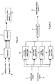
- Figure 1 illustrates an overall system block diagram of the general arrangement of the embodiments of the invention.
- a reference sequence comprising reference sequence fields/frames is input to a detector module 2.
- a test sequence of video fields/frames 8 (interchangeably referred to herein as either the test sequence, or the degraded sequence) is also input in to the detector module 2.
- the test sequence is obtained by inputting the reference sequence to a system to be tested (such as a video recording device, a broadcast system, or a video codec, for example), and then taking the output of the system under test as the test sequence.
- the detector module 2 acts to detect various video characteristics of the input reference and test video fields/frames and generates video characteristic values which are then output to an integration module 4.
- the integration module 4 integrates the video characteristics values together to give a predicted video quality value 10, which is output therefrom.
- FIG. 2 illustrates in more detail the arrangement of the embodiments of the invention.
- the reference and test video sequences are each input to four analysers, being a spatial frequency analyser 22, a luminance and chrominance power signal to noise ratio analyser 24, an edge analyser 26, and a texture analyser 28.
- the respective analysers act to generate various video characteristic values as a result of the respective forms of analysis which each performs, and the video characteristic values are input to an integration module 4.
- the integration module then combines the individual video characteristic values to generate a video quality value PDMOS 10, which is a quantitative value relating to the test video quality as assessed by the embodiment of the invention.
- the spatial frequency analyser 22 acts to analyse the input test video fields/frame and reference video fields/frames and generates pyramid SNR values PySNR(a, b) from a pyramid analysis of the input reference fields/frame and the test field/frame. Additionally, the luminance and chrominance PSNR analyser 24 compares the input reference field/frame and the input test field/frame to generate luminance and chrominance PSNR values which are then output. Similarly, the edge detector analyser 26 analyses the input reference field/frame and the input test field/frame and outputs a single edge detector value EDif.
- the texture analyser 26 analyses the test field/frame and the reference field/frame to calculate a parameter TextureDeg indicative of the texture within the present test field/frame, and a parameter TextureRef indicative of the texture within the present reference field/frame.
- a parameter TextureDeg indicative of the texture within the present test field/frame
- a parameter TextureRef indicative of the texture within the present reference field/frame.
- the spatial frequency analyser 26 comprises internally a first pyramid transform generator 222 which is arranged to receive as an input the test video fields/frames. Additionally provided is a second pyramid transform generator 224, which receives as an input the reference video fields/frames.
- the two pyramid transform generators 222 and 224 each operate identically to produce a pyramid array for each input field/frame, which is then fed to a pyramid SNR calculator 226 in order to generate a pyramid SNR measure between respective corresponding test video fields/frames and reference video fields/frames.
- the operation of the spatial frequency analyser 22 in producing the pyramid SNR measures will be described next with reference to Figures 4 to 6 .
- FIG. 5 is a flow diagram illustrating the steps performed by either of the pyramid transform generators 222 or 224 in producing respective pyramid arrays. Therefore, firstly at step 8.2 the pyramid transform generator receives an input field/frame from the respective sequence (i.e. test sequence or reference sequence). Then, at step 8.4 a counter stage is initialised to zero and a processing loop commenced in order to generate the pyramid array.
- the general procedure followed to generate the pyramid array is a three stage, two step procedure, wherein for each stage 0 to 2 horizontal analysis is performed followed by vertical analysis. The steps involved in one particular stage of horizontal and vertical analysis are described with respect to steps 8.6 to 8.20 next.
- step 8.20 the input field/frame is overwritten with the results of the vertical analysis performed at step 8.18 such that the values within the input field/frame array correspond to the results of the first stage of the spatial analysis.
- step 8.22 an evaluation is performed to determine whether each of the stages of the spatial analysis to generate the pyramid array have been performed, and if not processing returns back to step 8.4, wherein the stage value is incremented, and the steps of 8.6 to 8.20 repeated once again.
- the values within the input field/frame array are overwritten with the calculated vertical and horizontal limits, such that as processing proceeds step by step through each stage, the values held within the input field/frame array are converted into a pyramid structure each of four quadrants at each level.
- a pyramid array has been constructed which can be output at step 8.24.
- Figure 7(a) illustrates the contents of the input field/frame array after the end of the stage 0 processing whereupon it will be seen that the horizontal analysis step followed by the vertical analysis step causes the array to be split into four quadrants Q(stage, 0 to 3) wherein Q(0, 0) contains values corresponding to the average of blocks of 4 pixels of the input field/frame, Q(0 ,1) contains values corresponding to the horizontal difference of blocks of 4 pixels of the input field/frame, Q(0, 2) contains values corresponding to the vertical difference of blocks of 4 pixels, and Q(0, 3) contains values corresponding to the diagonal difference of blocks of 4 pixels.
- Q(0, 0) contains values corresponding to the average of blocks of 4 pixels of the input field/frame
- Q(0 ,1) contains values corresponding to the horizontal difference of blocks of 4 pixels of the input field/frame
- Q(0, 2) contains values corresponding to the vertical difference of blocks of 4 pixels
- Q(0, 3) contains values corresponding to the diagonal difference of blocks of 4 pixels.
- the quadrant Q(0,0) output from the stage 0 analysis as shown in Figure 7(a) is then used as the input to the second iteration of the FOR loop to perform the stage one processing, the results of which are shown in Figure 7(b) .
- the quadrant Q(0, 0) has been overwritten by results Q(1, 0 to 3) which relate to the analysis of 4 by 4 pixel blocks, but wherein each quadrant Q(1, 0 to 3) contains values relating to the average, horizontal difference, vertical difference, and diagonal difference as previously described in respect of the stage 0 output.
- the resulting pyramid array as shown in Figure 7(c) has a total of ten blocks of results, being three blocks Q(0, 1 to 3) from the stage 0 (2 by 2 pixel) analysis, three quadrants Q(1, 1 to 3) from the stage 1 (4 by 4 pixel) analysis, and four quadrants Q(2, 0 to 3) from the stage 2 (8 x 8 pixel) analysis.
- the procedure of Figure 8 to produce the pyramid arrays as shown in Figure 7 is performed by each of the pyramid transform generators 222 and 224 to produce respective pyramid arrays pref and pdeg which are then input to the SNR calculator 226.
- the operation of the pyramid SNR calculator 226 is shown in Figure 6 .
- the pyramid SNR calculator 226 receives the reference and degraded pyramid arrays from the pyramid transform generators 224 and 222 respectively.
- a processing loop is commenced which processes each value of the counter value stage from 0 to 2.
- a second, nested, processing loop which processes a counter value quadrant between values of 1 to 3 is commenced at step 9.6.
- Each calculated error measure E(stage, quadrant) is then stored at step 9.10, following which at steps 9.12 and 9.14 the values of the quadrant and stage counters are updated as appropriate to the processing loops.
- the operation of the processing loops of step 9.4 to 9.14 and step 9.6 to step 9.12 is to calculate an error measure value for each value of the counter stage and the counter quadrant.
- a further processing loop to process all the available values of the counter stage from 0 to 2 is commenced, following which at step 9.18 a nested processing loop to process the values of the quadrant counter 1 to 3 is commenced.
- the values of the counters stage and quadrant are incremented as appropriate to the processing loops, such that the effect of the nested processing loops is to calculate and store the PSNR measure for each value of stage and each value of quadrant.
- the parameter stage can take values of 0 to 2
- the parameter quadrant may take values of 1 to 3
- a total of 9 PSNR measures are generated by the pyramid SNR calculator 226, all of which may be output to the integration stage 4.
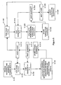
- Figure 7 illustrates the internal configuration of the edge analyser 26. More particularly, the edge analyser 26 comprises a first edge detector 262 arranged to receive and test the video fields/frames, and to detect edges therein, and a second edge detector 264 arranged to receive the reference video fields/frames output from the matching module 30, and to detect edges therein. Both the edge detectors 262 and 264 preferably operate in accordance with known edge detection algorithms and produce edge maps in a manner already known in the art. For example, examples of known edge detection algorithms are Laplacian edge detectors, Canny edge detectors, and Rothwell edge detectors.
- Source code in the C programming language for a Canny edge detector was available for free download via ftp before the priority date from ftp://figment.csee.usf.edu/pub/Edge Comparison/source code/canny.src whereas source code in C for a Rothwell edge detector was available from ftp://figment.csee.usf.edu/pub/Edge Comparison/source code/rothwell.src.
- the respective edge maps produced by each of the edge detectors 262 and 264 are input to a block matching means 266 which acts to compare the respective edge maps in a manner to be described, and to produce an output parameter EDif , representative of the comparison.
- the operation of the edge analyser 26 is shown in more detail in Figure 8 .
- the respective edge detectors 262 and 264 calculate respective reference and degraded edge maps.
- the edge detection algorithm used by the edge detectors 262 and 264 is preferably one which is known in the art, such as a Canny edge detector.
- the edge detectors 262 and 264 output the reference and degraded edge maps to the block matching means 266, wherein at step 11.4 each of the reference and degraded edge maps are split into n by m blocks.
- the block matching means 266 acts to count each pixel which forms part of an edge within each block in both of the reference and the degraded edge maps.
- the block matching means 266 has obtained a count of edge pixels for each block in each of the reference and degraded edge maps.
- step 11.8 the block matching means 266 calculates the difference in respective pixel counts between corresponding blocks in the reference and the degraded edge maps. Therefore, after step 11.8 as many difference values as there are blocks in one of the reference or degraded edge maps will have been obtained.
- step 11.10 the block matching means 266 puts each difference value to the power Q and at step 11.12 the resulting values are summed. Therefore, after step 11.10 there are still as many values as there are blocks in one of the reference or degraded edge maps, but after step 11.12 a single result is obtained corresponding to a sum of the values calculated at step 11.10.
- step 11.14 the resulting sum value is then put to the power 1/Q, and at step 11.16 the result of this calculation is output from the block matching means 266 as the EDif parameter.
- the EDif parameter is output from the edge analyser 26 to the integration stage 4. Use of the EDif parameter within the integration stage will be described later.
- the block matching means After producing the respective edge maps, the block matching means then calculates a measure of the number of edge-marked pixels in each analysis block, where nX and nY define the number of non-overlapping blocks to be analysed in the horizontal and vertical directions and X1 and Y1 define analysis offsets from the field edge.
- EMap Re f ⁇ Nx + X ⁇ 1 + i , My + Y ⁇ 1 + j x 0..
- ⁇ nX - 1 , y 0..
- equations 11-1 to 11-7 are substantially identical with that already described in respect of Figure 11 , with the differences that the analysis offsets from the field/frame edges are taken into account.
- the parameter Edif found by equation 11-5 is output to the integration stage 4 in the same manner as previously described.
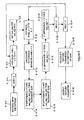
- Texture analysis can therefore yield important information on such compression, and is used within the present embodiment to provide a video characteristic value TextureDeg and TextureRef. More particularly, the texture parameter values TextureDeg and TextureRef are measured by recording the number of turning points in the intensity signal along horizontal picture lines. This is performed as shown in Figure 9 .
- the texture analyser 28 receives the present test field/frame to be processed. From Figure 2 it will be recalled that the texture analyser 28 receives the test video field/frame, and the original reference field/frame. However, in other embodiments the texture analyser 28 may receive only one of the reference field/frame or the test field/frame in which case only one TextureDeg or TextureRef parameter is calculated as appropriate.
- a turning point counter sum is initialised to zero.
- values last_pos, and last_neg are both initialised to 0.
- a second, nested, processing loop is commenced to process each pixel x within each line y , where x takes the value of 0 to X -2, wherein X is the number of pixels in a line of the input video field/frame.
- a difference value is calculated between the pixel value at position x , and the pixel value at position x +1. Then, at step 12.14 an evaluation is performed to determine whether or not the calculated difference value is greater than 0, and also as to whether or not the value last_neg is greater than the value last_pos. If this logical condition is met then the counter value sum is incremented. Following step 12.14, at step 12.16 a second evaluation is performed to determine whether or not the difference value calculated at step 12.12 is less than 0, and as to whether or not the value last_neg is less than the value last_pos. If this is the case then the counter value sum is incremented.
- step 12.14 and step 12.16 are mutually exclusive, and that it is not possible for the counter value sum to be incremented twice for any single particular pixel.
- step 12.18 a further evaluation is determined as to whether or not the calculated difference value is greater than zero, in which case the value last_pos is set to be the number of the current pixel x .
- step 12.20 a second evaluation is performed which evaluates as to whether or not the calculated difference value is less than zero, in which case the counter value last_neg is set to be the current pixel number x .
- step 12.22 an evaluation is performed to determine whether or not all of the pixels x within the present line have been processed, and if not then processing proceeds back to step 12.10 wherein the next pixel is processed. However, if all of the pixels have been processed then processing proceeds to step 12.24, wherein an evaluation is made to determine whether or not all of the lines y have been processed in the present input frame, and if not then processing proceeds back to step 12.6, when processing of the next line is commenced.
- the results of these nested processing loops are that each pixel on each line is processed, and whenever the evaluations of steps 12.14 and steps 12.16 return true the counter sum is incremented. Therefore, after the processing loops have finished, the counter sum will contain a certain value which is indicative of the texture turning points within the input field/frame.
- the texture parameter thus calculated may be output from the texture analyser 28 to the integrator stage 4 at step 12.28.
- VPSNR 10.0 * log 10 ⁇ 255 2
- the operation of the integration stage is to produce an estimate of the perceived video quality of the test video sequence by the appropriate weighting of a selection of the video characteristic parameter values produced by the analysers 22 to 28.
- the particular set of parameter values used and the values of the corresponding weighting factors depend upon the particular type of video being tested, and are determined in advance by prior calibration.
- the calibrations are performed on a large set of video sequences that have known subjective scores, and preferably have properties similar to the degraded sequences to be tested.
- the general form of the integration procedure firstly time weights the field/frame by field/frame detection parameters, and then combines the time-weighted and averaged values to give a predicted quality score, being the overall video quality value.
- the process to achieve this is set out in Figure 10 .
- the integration stage 4 receives the parameter values output from the various detectors and analysers at step 13.2 and stores them.
- the spatial frequency analyser 22 outputs the PySNR values
- the luminance and chrominance power signal to noise ratio analyser 24 outputs PSNR values for each of the luminance and chrominance characteristics in the colour model being used.
- the edge analyser 26 outputs at the EDif parameter as described previously
- the texture analyser 28 gives the values TextureDeg at least, but might also output values TextureRef and TextureMref if appropriate.
- the integration stage receives the output information and stores it.
- the integration stage selects the video type, and as a result selects a set of integration parameters in dependence on the video type.
- weighting values for 525 line video are: Table 2 Integration parameters for 525 broadcast video.
- each set of integration parameters is stored within the integration stage 4 in look-up tables or the like.
- a processing loop is commenced in order to process each integration parameter type k within the values 0 to K -1, wherein each parameter ( k ) is a particular one of the parameters received from the various analysers or the matching module.
- the time weighted average value AvD(k) is multiplied by the appropriate weighting factor w(k), and the product stored.
- the appropriate weighting factor w(k) is read from the appropriate look up table for the video type stored in the integration stage 4.
- the output video quality value PDMOS may be put to a number of uses. In particular, it may be used to evaluate the quality of an existing video service to ensure that the quality is adequate, or alternatively it may be used to test the performance of different video codecs. Additionally, the video quality value may be used to evaluate the performance of new video services, such as broadband-style video services over the Internet.
Landscapes
- Engineering & Computer Science (AREA)
- Physics & Mathematics (AREA)
- Theoretical Computer Science (AREA)
- General Physics & Mathematics (AREA)
- Multimedia (AREA)
- Computer Vision & Pattern Recognition (AREA)
- Signal Processing (AREA)
- General Health & Medical Sciences (AREA)
- Biomedical Technology (AREA)
- Health & Medical Sciences (AREA)
- Quality & Reliability (AREA)
- Testing, Inspecting, Measuring Of Stereoscopic Televisions And Televisions (AREA)
- Image Analysis (AREA)
- Compression Or Coding Systems Of Tv Signals (AREA)
- Closed-Circuit Television Systems (AREA)
Applications Claiming Priority (2)
| Application Number | Priority Date | Filing Date | Title |
|---|---|---|---|
| GBGB0314162.9A GB0314162D0 (en) | 2003-06-18 | 2003-06-18 | Edge analysis in video quality assessment |
| PCT/GB2004/002400 WO2004114216A1 (en) | 2003-06-18 | 2004-06-04 | Edge analysis in video quality assessment |
Publications (2)
| Publication Number | Publication Date |
|---|---|
| EP1634242A1 EP1634242A1 (en) | 2006-03-15 |
| EP1634242B1 true EP1634242B1 (en) | 2011-11-23 |
Family
ID=27636816
Family Applications (1)
| Application Number | Title | Priority Date | Filing Date |
|---|---|---|---|
| EP04736083A Expired - Lifetime EP1634242B1 (en) | 2003-06-18 | 2004-06-04 | Edge analysis in video quality assessment |
Country Status (11)
| Country | Link |
|---|---|
| US (1) | US7812857B2 (https=) |
| EP (1) | EP1634242B1 (https=) |
| JP (1) | JP5117720B2 (https=) |
| KR (1) | KR101031685B1 (https=) |
| CN (1) | CN100343877C (https=) |
| AT (1) | ATE534975T1 (https=) |
| AU (1) | AU2004250357B2 (https=) |
| CA (1) | CA2517354C (https=) |
| ES (1) | ES2376235T3 (https=) |
| GB (1) | GB0314162D0 (https=) |
| WO (1) | WO2004114216A1 (https=) |
Families Citing this family (24)
| Publication number | Priority date | Publication date | Assignee | Title |
|---|---|---|---|---|
| GB0314161D0 (en) * | 2003-06-18 | 2003-07-23 | British Telecomm | Edge analysis in video quality assessment |
| KR100541961B1 (ko) * | 2004-06-08 | 2006-01-12 | 삼성전자주식회사 | 선명도 향상 및 잡음처리가 가능한 영상신호 처리장치 및방법 |
| CA2582531C (en) * | 2004-10-18 | 2013-03-12 | Nippon Telegraph And Telephone Corporation | Video quality objective evaluation device, evaluation method, and program |
| WO2006099743A1 (en) * | 2005-03-25 | 2006-09-28 | Algolith Inc. | Apparatus and method for objective assessment of dct-coded video quality with or without an original video sequence |
| CN101356827B (zh) * | 2005-12-05 | 2011-02-02 | 英国电讯有限公司 | 非介入式视频质量测量 |
| JP4490483B2 (ja) * | 2006-05-09 | 2010-06-23 | 日本電信電話株式会社 | 映像品質推定装置、方法、およびプログラム |
| WO2008060022A1 (en) * | 2006-11-13 | 2008-05-22 | Electronics And Telecommunications Research Institute | System and method for evaluating and certifying image identifier |
| EP2137976B1 (en) * | 2007-04-09 | 2017-06-07 | Tektronix, Inc. | Systems and methods for spatially isolated artifact dissection, classification and measurement |
| US20090010341A1 (en) * | 2007-07-02 | 2009-01-08 | Feng Pan | Peak signal to noise ratio weighting module, video encoding system and method for use therewith |
| US8218811B2 (en) | 2007-09-28 | 2012-07-10 | Uti Limited Partnership | Method and system for video interaction based on motion swarms |
| US8086007B2 (en) | 2007-10-18 | 2011-12-27 | Siemens Aktiengesellschaft | Method and system for human vision model guided medical image quality assessment |
| EP2114080A1 (en) * | 2008-04-30 | 2009-11-04 | Thomson Licensing | Method for assessing the quality of a distorted version of a frame sequence |
| US20090309977A1 (en) * | 2008-06-12 | 2009-12-17 | Microsoft Corporation | Benchmarking and calibrating video quality assessment tools |
| US8270695B2 (en) * | 2008-10-07 | 2012-09-18 | Carestream Health, Inc. | Diagnostic image processing with automatic self image quality validation |
| CN101599170B (zh) * | 2009-06-26 | 2011-09-14 | 东方网力科技股份有限公司 | 图像噪声评价方法、图像噪声评价装置 |
| CN101998137B (zh) | 2009-08-21 | 2016-09-07 | 华为技术有限公司 | 视频质量参数获取方法和装置及电子设备 |
| JP5350300B2 (ja) * | 2010-03-24 | 2013-11-27 | 日本電信電話株式会社 | トランスコード映像品質客観評価装置及び方法及びプログラム |
| JP2014527778A (ja) * | 2011-08-29 | 2014-10-16 | アイ.シー.ブイ.ティー リミテッド | ビデオコンテンツシステムの制御 |
| US8525883B2 (en) | 2011-09-02 | 2013-09-03 | Sharp Laboratories Of America, Inc. | Methods, systems and apparatus for automatic video quality assessment |
| CN102761771A (zh) * | 2012-06-29 | 2012-10-31 | 无锡风格软件有限公司 | 一种基于图像客观质量评估进行视频劣播检测的方法及设备 |
| CN103325113B (zh) * | 2013-06-06 | 2016-03-09 | 深圳大学 | 部分参考型图像质量评价方法及装置 |
| US9412024B2 (en) * | 2013-09-13 | 2016-08-09 | Interra Systems, Inc. | Visual descriptors based video quality assessment using outlier model |
| JP6402088B2 (ja) * | 2015-11-18 | 2018-10-10 | 日本電信電話株式会社 | 映像品質推定装置、映像品質推定方法、及びプログラム |
| CN112016538B (zh) * | 2020-10-29 | 2021-06-15 | 腾讯科技(深圳)有限公司 | 视频处理方法、装置、计算机设备和存储介质 |
Family Cites Families (29)
| Publication number | Priority date | Publication date | Assignee | Title |
|---|---|---|---|---|
| US5126990A (en) | 1982-01-12 | 1992-06-30 | Discovision Associates | Method of evaluating a storage medium by recirculating a test sample of a signal |
| US5214508A (en) | 1992-02-14 | 1993-05-25 | Tektronix, Inc. | Spatial bandwidth testing for digital data-compressed video systems |
| JPH0611969A (ja) * | 1992-06-26 | 1994-01-21 | Canon Inc | 画像形成装置 |
| KR950005601B1 (ko) * | 1992-09-19 | 1995-05-27 | 삼성전자주식회사 | 디지탈 영상 안정화 방법 및 시스템 |
| JPH06125545A (ja) * | 1992-10-12 | 1994-05-06 | Toko Inc | 画像圧縮伸張装置の画質評価方法 |
| US5446492A (en) * | 1993-01-19 | 1995-08-29 | Wolf; Stephen | Perception-based video quality measurement system |
| US5838828A (en) * | 1995-12-12 | 1998-11-17 | Massachusetts Institute Of Technology | Method and apparatus for motion estimation in a video signal |
| JP2001111842A (ja) * | 1996-08-29 | 2001-04-20 | Fuji Xerox Co Ltd | 画質制御装置 |
| US6363116B1 (en) | 1997-04-04 | 2002-03-26 | Tektronix, Inc. | Picture quality assessment using spatial location with or without subsampling |
| US6434275B1 (en) * | 1997-05-28 | 2002-08-13 | Sony Corporation | Block distortion reduction method and device and encoding method and device |
| DE69803830T2 (de) | 1998-03-02 | 2002-09-12 | Koninklijke Kpn N.V., Groningen | Verfahren, Vorrichtung, ASIC und deren Benutzung zur objektiven Videoqualitätbewertung |
| GB9805035D0 (en) * | 1998-03-10 | 1998-05-06 | Nds Ltd | Estimating the difference in picture quality between two versions of a video signal |
| JP3501954B2 (ja) * | 1998-07-21 | 2004-03-02 | 日本放送協会 | 画質評価装置 |
| US6466832B1 (en) * | 1998-08-24 | 2002-10-15 | Altec Lansing R & D Center Israel | High quality wireless audio speakers |
| US6496221B1 (en) * | 1998-11-02 | 2002-12-17 | The United States Of America As Represented By The Secretary Of Commerce | In-service video quality measurement system utilizing an arbitrary bandwidth ancillary data channel |
| US6480632B2 (en) * | 1998-12-03 | 2002-11-12 | Intel Corporation | Method and apparatus to interpolate video frames |
| CA2371998C (en) * | 1999-02-11 | 2006-01-24 | British Telecommunications Public Limited Company | Analysis of video signal quality |
| US6493023B1 (en) * | 1999-03-12 | 2002-12-10 | The United States Of America As Represented By The Administrator Of The National Aeronautics And Space Administration | Method and apparatus for evaluating the visual quality of processed digital video sequences |
| JP2000341512A (ja) * | 1999-05-27 | 2000-12-08 | Matsushita Electric Ind Co Ltd | 画像読み取り装置 |
| JP2003016443A (ja) * | 2001-07-02 | 2003-01-17 | Konica Corp | 画質評価方法および画質評価装置ならびに画質評価用チャート画像 |
| US6822675B2 (en) * | 2001-07-03 | 2004-11-23 | Koninklijke Philips Electronics N.V. | Method of measuring digital video quality |
| US6577764B2 (en) * | 2001-08-01 | 2003-06-10 | Teranex, Inc. | Method for measuring and analyzing digital video quality |
| US20030035581A1 (en) | 2001-08-13 | 2003-02-20 | Nokia Mobile Phones, Ltd. | Method and system for measuring perceptual distortion in images |
| US7119854B2 (en) | 2001-12-28 | 2006-10-10 | Koninklijke Philips Electronics N.V. | Method for deriving an objective sharpness metric |
| US7038710B2 (en) * | 2002-07-17 | 2006-05-02 | Koninklijke Philips Electronics, N.V. | Method and apparatus for measuring the quality of video data |
| US7099518B2 (en) * | 2002-07-18 | 2006-08-29 | Tektronix, Inc. | Measurement of blurring in video sequences |
| JP4194029B2 (ja) * | 2003-02-26 | 2008-12-10 | Kddi株式会社 | 画像劣化自動検出装置 |
| US20040175056A1 (en) * | 2003-03-07 | 2004-09-09 | Chulhee Lee | Methods and systems for objective measurement of video quality |
| GB0314161D0 (en) | 2003-06-18 | 2003-07-23 | British Telecomm | Edge analysis in video quality assessment |
-
2003
- 2003-06-18 GB GBGB0314162.9A patent/GB0314162D0/en not_active Ceased
-
2004
- 2004-06-04 US US10/558,673 patent/US7812857B2/en active Active
- 2004-06-04 WO PCT/GB2004/002400 patent/WO2004114216A1/en not_active Ceased
- 2004-06-04 CA CA2517354A patent/CA2517354C/en not_active Expired - Fee Related
- 2004-06-04 JP JP2006516377A patent/JP5117720B2/ja not_active Expired - Lifetime
- 2004-06-04 AT AT04736083T patent/ATE534975T1/de active
- 2004-06-04 AU AU2004250357A patent/AU2004250357B2/en not_active Ceased
- 2004-06-04 EP EP04736083A patent/EP1634242B1/en not_active Expired - Lifetime
- 2004-06-04 CN CNB200480007626XA patent/CN100343877C/zh not_active Expired - Lifetime
- 2004-06-04 KR KR1020057019127A patent/KR101031685B1/ko not_active Expired - Lifetime
- 2004-06-04 ES ES04736083T patent/ES2376235T3/es not_active Expired - Lifetime
Also Published As
| Publication number | Publication date |
|---|---|
| US7812857B2 (en) | 2010-10-12 |
| WO2004114216A1 (en) | 2004-12-29 |
| KR20060018822A (ko) | 2006-03-02 |
| AU2004250357A1 (en) | 2004-12-29 |
| CN100343877C (zh) | 2007-10-17 |
| AU2004250357B2 (en) | 2010-07-08 |
| US20060274618A1 (en) | 2006-12-07 |
| EP1634242A1 (en) | 2006-03-15 |
| CN1761975A (zh) | 2006-04-19 |
| ATE534975T1 (de) | 2011-12-15 |
| CA2517354A1 (en) | 2004-12-29 |
| JP2006527948A (ja) | 2006-12-07 |
| GB0314162D0 (en) | 2003-07-23 |
| ES2376235T3 (es) | 2012-03-12 |
| JP5117720B2 (ja) | 2013-01-16 |
| CA2517354C (en) | 2013-02-19 |
| KR101031685B1 (ko) | 2011-04-29 |
Similar Documents
| Publication | Publication Date | Title |
|---|---|---|
| EP1634242B1 (en) | Edge analysis in video quality assessment | |
| EP1636755B1 (en) | Method and system for video quality assessment | |
| Lukac et al. | Demosaicked image postprocessing using local color ratios | |
| CN101682796B (zh) | 用于视频质量评估的方法和系统 | |
| Lubin | A human vision system model for objective picture quality measurements | |
| JP2003501850A (ja) | 基準映像を用いることなくデジタル映像の品質を推定する方法と装置 | |
| JP2000069487A (ja) | ビデオシ―ケンスのノイズレベルの推定方法 | |
| EP2466906B1 (en) | System and methods to measure noise and to generate picture quality prediction from source having no reference | |
| EP1440581B1 (en) | Unit for and method of motion estimation, and image processing apparatus provided with such motion estimation unit | |
| US20040175056A1 (en) | Methods and systems for objective measurement of video quality | |
| US20130202199A1 (en) | Using higher order statistics to estimate pixel values in digital image processing to improve accuracy and computation efficiency | |
| US20030035581A1 (en) | Method and system for measuring perceptual distortion in images | |
| Roja et al. | Saliency based assessment of videos from frame-wise quality measures | |
| Guarneri et al. | A perceptual quality metric for color-interpolated images | |
| Park et al. | Weighted sum-based color filter array interpolation using Taylor Series cubic approximation | |
| Ouni et al. | SCID: full reference spatial color image quality metric | |
| Farias | Visual‐quality estimation using objective metrics | |
| KR20010006040A (ko) | 두개의 신호 시퀀스들 사이의 가시성 차이들을 평가하기 위한 방법 및 장치 |
Legal Events
| Date | Code | Title | Description |
|---|---|---|---|
| PUAI | Public reference made under article 153(3) epc to a published international application that has entered the european phase |
Free format text: ORIGINAL CODE: 0009012 |
|
| 17P | Request for examination filed |
Effective date: 20050823 |
|
| AK | Designated contracting states |
Kind code of ref document: A1 Designated state(s): AT BE BG CH CY CZ DE DK EE ES FI FR GB GR HU IE IT LI LU MC NL PL PT RO SE SI SK TR |
|
| DAX | Request for extension of the european patent (deleted) | ||
| GRAP | Despatch of communication of intention to grant a patent |
Free format text: ORIGINAL CODE: EPIDOSNIGR1 |
|
| GRAS | Grant fee paid |
Free format text: ORIGINAL CODE: EPIDOSNIGR3 |
|
| GRAA | (expected) grant |
Free format text: ORIGINAL CODE: 0009210 |
|
| AK | Designated contracting states |
Kind code of ref document: B1 Designated state(s): AT BE BG CH CY CZ DE DK EE ES FI FR GB GR HU IE IT LI LU MC NL PL PT RO SE SI SK TR |
|
| REG | Reference to a national code |
Ref country code: GB Ref legal event code: FG4D |
|
| REG | Reference to a national code |
Ref country code: CH Ref legal event code: EP |
|
| REG | Reference to a national code |
Ref country code: IE Ref legal event code: FG4D |
|
| REG | Reference to a national code |
Ref country code: DE Ref legal event code: R096 Ref document number: 602004035409 Country of ref document: DE Effective date: 20120119 |
|
| REG | Reference to a national code |
Ref country code: NL Ref legal event code: T3 |
|
| REG | Reference to a national code |
Ref country code: ES Ref legal event code: FG2A Ref document number: 2376235 Country of ref document: ES Kind code of ref document: T3 Effective date: 20120312 |
|
| PG25 | Lapsed in a contracting state [announced via postgrant information from national office to epo] |
Ref country code: SE Free format text: LAPSE BECAUSE OF FAILURE TO SUBMIT A TRANSLATION OF THE DESCRIPTION OR TO PAY THE FEE WITHIN THE PRESCRIBED TIME-LIMIT Effective date: 20111123 Ref country code: BE Free format text: LAPSE BECAUSE OF FAILURE TO SUBMIT A TRANSLATION OF THE DESCRIPTION OR TO PAY THE FEE WITHIN THE PRESCRIBED TIME-LIMIT Effective date: 20111123 Ref country code: PT Free format text: LAPSE BECAUSE OF FAILURE TO SUBMIT A TRANSLATION OF THE DESCRIPTION OR TO PAY THE FEE WITHIN THE PRESCRIBED TIME-LIMIT Effective date: 20120323 Ref country code: GR Free format text: LAPSE BECAUSE OF FAILURE TO SUBMIT A TRANSLATION OF THE DESCRIPTION OR TO PAY THE FEE WITHIN THE PRESCRIBED TIME-LIMIT Effective date: 20120224 Ref country code: SI Free format text: LAPSE BECAUSE OF FAILURE TO SUBMIT A TRANSLATION OF THE DESCRIPTION OR TO PAY THE FEE WITHIN THE PRESCRIBED TIME-LIMIT Effective date: 20111123 |
|
| PG25 | Lapsed in a contracting state [announced via postgrant information from national office to epo] |
Ref country code: CY Free format text: LAPSE BECAUSE OF FAILURE TO SUBMIT A TRANSLATION OF THE DESCRIPTION OR TO PAY THE FEE WITHIN THE PRESCRIBED TIME-LIMIT Effective date: 20111123 |
|
| PG25 | Lapsed in a contracting state [announced via postgrant information from national office to epo] |
Ref country code: BG Free format text: LAPSE BECAUSE OF FAILURE TO SUBMIT A TRANSLATION OF THE DESCRIPTION OR TO PAY THE FEE WITHIN THE PRESCRIBED TIME-LIMIT Effective date: 20120223 Ref country code: CZ Free format text: LAPSE BECAUSE OF FAILURE TO SUBMIT A TRANSLATION OF THE DESCRIPTION OR TO PAY THE FEE WITHIN THE PRESCRIBED TIME-LIMIT Effective date: 20111123 Ref country code: EE Free format text: LAPSE BECAUSE OF FAILURE TO SUBMIT A TRANSLATION OF THE DESCRIPTION OR TO PAY THE FEE WITHIN THE PRESCRIBED TIME-LIMIT Effective date: 20111123 Ref country code: SK Free format text: LAPSE BECAUSE OF FAILURE TO SUBMIT A TRANSLATION OF THE DESCRIPTION OR TO PAY THE FEE WITHIN THE PRESCRIBED TIME-LIMIT Effective date: 20111123 Ref country code: DK Free format text: LAPSE BECAUSE OF FAILURE TO SUBMIT A TRANSLATION OF THE DESCRIPTION OR TO PAY THE FEE WITHIN THE PRESCRIBED TIME-LIMIT Effective date: 20111123 |
|
| PG25 | Lapsed in a contracting state [announced via postgrant information from national office to epo] |
Ref country code: PL Free format text: LAPSE BECAUSE OF FAILURE TO SUBMIT A TRANSLATION OF THE DESCRIPTION OR TO PAY THE FEE WITHIN THE PRESCRIBED TIME-LIMIT Effective date: 20111123 Ref country code: RO Free format text: LAPSE BECAUSE OF FAILURE TO SUBMIT A TRANSLATION OF THE DESCRIPTION OR TO PAY THE FEE WITHIN THE PRESCRIBED TIME-LIMIT Effective date: 20111123 |
|
| REG | Reference to a national code |
Ref country code: AT Ref legal event code: MK05 Ref document number: 534975 Country of ref document: AT Kind code of ref document: T Effective date: 20111123 |
|
| PLBE | No opposition filed within time limit |
Free format text: ORIGINAL CODE: 0009261 |
|
| STAA | Information on the status of an ep patent application or granted ep patent |
Free format text: STATUS: NO OPPOSITION FILED WITHIN TIME LIMIT |
|
| 26N | No opposition filed |
Effective date: 20120824 |
|
| REG | Reference to a national code |
Ref country code: DE Ref legal event code: R097 Ref document number: 602004035409 Country of ref document: DE Effective date: 20120824 |
|
| PG25 | Lapsed in a contracting state [announced via postgrant information from national office to epo] |
Ref country code: AT Free format text: LAPSE BECAUSE OF FAILURE TO SUBMIT A TRANSLATION OF THE DESCRIPTION OR TO PAY THE FEE WITHIN THE PRESCRIBED TIME-LIMIT Effective date: 20111123 Ref country code: MC Free format text: LAPSE BECAUSE OF NON-PAYMENT OF DUE FEES Effective date: 20120630 |
|
| REG | Reference to a national code |
Ref country code: CH Ref legal event code: PL |
|
| REG | Reference to a national code |
Ref country code: CH Ref legal event code: PL |
|
| REG | Reference to a national code |
Ref country code: IE Ref legal event code: MM4A |
|
| PG25 | Lapsed in a contracting state [announced via postgrant information from national office to epo] |
Ref country code: IE Free format text: LAPSE BECAUSE OF NON-PAYMENT OF DUE FEES Effective date: 20120604 Ref country code: CH Free format text: LAPSE BECAUSE OF NON-PAYMENT OF DUE FEES Effective date: 20120630 Ref country code: LI Free format text: LAPSE BECAUSE OF NON-PAYMENT OF DUE FEES Effective date: 20120630 |
|
| PG25 | Lapsed in a contracting state [announced via postgrant information from national office to epo] |
Ref country code: FI Free format text: LAPSE BECAUSE OF FAILURE TO SUBMIT A TRANSLATION OF THE DESCRIPTION OR TO PAY THE FEE WITHIN THE PRESCRIBED TIME-LIMIT Effective date: 20111123 |
|
| PG25 | Lapsed in a contracting state [announced via postgrant information from national office to epo] |
Ref country code: TR Free format text: LAPSE BECAUSE OF FAILURE TO SUBMIT A TRANSLATION OF THE DESCRIPTION OR TO PAY THE FEE WITHIN THE PRESCRIBED TIME-LIMIT Effective date: 20111123 |
|
| PG25 | Lapsed in a contracting state [announced via postgrant information from national office to epo] |
Ref country code: LU Free format text: LAPSE BECAUSE OF NON-PAYMENT OF DUE FEES Effective date: 20120604 |
|
| PG25 | Lapsed in a contracting state [announced via postgrant information from national office to epo] |
Ref country code: HU Free format text: LAPSE BECAUSE OF FAILURE TO SUBMIT A TRANSLATION OF THE DESCRIPTION OR TO PAY THE FEE WITHIN THE PRESCRIBED TIME-LIMIT Effective date: 20040604 |
|
| REG | Reference to a national code |
Ref country code: FR Ref legal event code: PLFP Year of fee payment: 13 |
|
| REG | Reference to a national code |
Ref country code: FR Ref legal event code: PLFP Year of fee payment: 14 |
|
| REG | Reference to a national code |
Ref country code: FR Ref legal event code: PLFP Year of fee payment: 15 |
|
| PGFP | Annual fee paid to national office [announced via postgrant information from national office to epo] |
Ref country code: NL Payment date: 20200525 Year of fee payment: 17 |
|
| PGFP | Annual fee paid to national office [announced via postgrant information from national office to epo] |
Ref country code: IT Payment date: 20200519 Year of fee payment: 17 |
|
| PGFP | Annual fee paid to national office [announced via postgrant information from national office to epo] |
Ref country code: ES Payment date: 20200701 Year of fee payment: 17 |
|
| REG | Reference to a national code |
Ref country code: NL Ref legal event code: MM Effective date: 20210701 |
|
| PG25 | Lapsed in a contracting state [announced via postgrant information from national office to epo] |
Ref country code: NL Free format text: LAPSE BECAUSE OF NON-PAYMENT OF DUE FEES Effective date: 20210701 |
|
| PG25 | Lapsed in a contracting state [announced via postgrant information from national office to epo] |
Ref country code: IT Free format text: LAPSE BECAUSE OF NON-PAYMENT OF DUE FEES Effective date: 20210604 |
|
| REG | Reference to a national code |
Ref country code: ES Ref legal event code: FD2A Effective date: 20220801 |
|
| PG25 | Lapsed in a contracting state [announced via postgrant information from national office to epo] |
Ref country code: ES Free format text: LAPSE BECAUSE OF NON-PAYMENT OF DUE FEES Effective date: 20210605 |
|
| PGFP | Annual fee paid to national office [announced via postgrant information from national office to epo] |
Ref country code: FR Payment date: 20230523 Year of fee payment: 20 Ref country code: DE Payment date: 20230523 Year of fee payment: 20 |
|
| PGFP | Annual fee paid to national office [announced via postgrant information from national office to epo] |
Ref country code: GB Payment date: 20230523 Year of fee payment: 20 |
|
| REG | Reference to a national code |
Ref country code: DE Ref legal event code: R071 Ref document number: 602004035409 Country of ref document: DE |
|
| REG | Reference to a national code |
Ref country code: GB Ref legal event code: PE20 Expiry date: 20240603 |
|
| PG25 | Lapsed in a contracting state [announced via postgrant information from national office to epo] |
Ref country code: GB Free format text: LAPSE BECAUSE OF EXPIRATION OF PROTECTION Effective date: 20240603 |
|
| PG25 | Lapsed in a contracting state [announced via postgrant information from national office to epo] |
Ref country code: GB Free format text: LAPSE BECAUSE OF EXPIRATION OF PROTECTION Effective date: 20240603 |