EP1634021B1 - Chambre de combustion annulaire de turbomachine - Google Patents
Chambre de combustion annulaire de turbomachine Download PDFInfo
- Publication number
- EP1634021B1 EP1634021B1 EP04767843.8A EP04767843A EP1634021B1 EP 1634021 B1 EP1634021 B1 EP 1634021B1 EP 04767843 A EP04767843 A EP 04767843A EP 1634021 B1 EP1634021 B1 EP 1634021B1
- Authority
- EP
- European Patent Office
- Prior art keywords
- holes
- chamber
- combustion chamber
- perforations
- effectively
- Prior art date
- Legal status (The legal status is an assumption and is not a legal conclusion. Google has not performed a legal analysis and makes no representation as to the accuracy of the status listed.)
- Expired - Lifetime
Links
- 238000002485 combustion reaction Methods 0.000 title claims description 59
- 238000001816 cooling Methods 0.000 claims description 30
- 238000002347 injection Methods 0.000 claims description 23
- 239000007924 injection Substances 0.000 claims description 23
- 230000001154 acute effect Effects 0.000 claims description 16
- 239000000446 fuel Substances 0.000 claims description 5
- 230000007423 decrease Effects 0.000 claims description 4
- 238000011144 upstream manufacturing Methods 0.000 description 8
- 238000010790 dilution Methods 0.000 description 5
- 239000012895 dilution Substances 0.000 description 5
- 230000003247 decreasing effect Effects 0.000 description 3
- 230000000694 effects Effects 0.000 description 2
- 230000001627 detrimental effect Effects 0.000 description 1
- 238000007710 freezing Methods 0.000 description 1
- 230000008014 freezing Effects 0.000 description 1
- 238000012986 modification Methods 0.000 description 1
- 230000004048 modification Effects 0.000 description 1
- 230000005855 radiation Effects 0.000 description 1
- 238000003466 welding Methods 0.000 description 1
Images


Classifications
-
- F—MECHANICAL ENGINEERING; LIGHTING; HEATING; WEAPONS; BLASTING
- F23—COMBUSTION APPARATUS; COMBUSTION PROCESSES
- F23R—GENERATING COMBUSTION PRODUCTS OF HIGH PRESSURE OR HIGH VELOCITY, e.g. GAS-TURBINE COMBUSTION CHAMBERS
- F23R3/00—Continuous combustion chambers using liquid or gaseous fuel
- F23R3/42—Continuous combustion chambers using liquid or gaseous fuel characterised by the arrangement or form of the flame tubes or combustion chambers
- F23R3/50—Combustion chambers comprising an annular flame tube within an annular casing
-
- F—MECHANICAL ENGINEERING; LIGHTING; HEATING; WEAPONS; BLASTING
- F23—COMBUSTION APPARATUS; COMBUSTION PROCESSES
- F23R—GENERATING COMBUSTION PRODUCTS OF HIGH PRESSURE OR HIGH VELOCITY, e.g. GAS-TURBINE COMBUSTION CHAMBERS
- F23R3/00—Continuous combustion chambers using liquid or gaseous fuel
-
- F—MECHANICAL ENGINEERING; LIGHTING; HEATING; WEAPONS; BLASTING
- F23—COMBUSTION APPARATUS; COMBUSTION PROCESSES
- F23R—GENERATING COMBUSTION PRODUCTS OF HIGH PRESSURE OR HIGH VELOCITY, e.g. GAS-TURBINE COMBUSTION CHAMBERS
- F23R3/00—Continuous combustion chambers using liquid or gaseous fuel
- F23R3/002—Wall structures
-
- F—MECHANICAL ENGINEERING; LIGHTING; HEATING; WEAPONS; BLASTING
- F23—COMBUSTION APPARATUS; COMBUSTION PROCESSES
- F23R—GENERATING COMBUSTION PRODUCTS OF HIGH PRESSURE OR HIGH VELOCITY, e.g. GAS-TURBINE COMBUSTION CHAMBERS
- F23R3/00—Continuous combustion chambers using liquid or gaseous fuel
- F23R3/02—Continuous combustion chambers using liquid or gaseous fuel characterised by the air-flow or gas-flow configuration
- F23R3/04—Air inlet arrangements
- F23R3/10—Air inlet arrangements for primary air
-
- F—MECHANICAL ENGINEERING; LIGHTING; HEATING; WEAPONS; BLASTING
- F23—COMBUSTION APPARATUS; COMBUSTION PROCESSES
- F23R—GENERATING COMBUSTION PRODUCTS OF HIGH PRESSURE OR HIGH VELOCITY, e.g. GAS-TURBINE COMBUSTION CHAMBERS
- F23R2900/00—Special features of, or arrangements for continuous combustion chambers; Combustion processes therefor
- F23R2900/03041—Effusion cooled combustion chamber walls or domes
-
- F—MECHANICAL ENGINEERING; LIGHTING; HEATING; WEAPONS; BLASTING
- F23—COMBUSTION APPARATUS; COMBUSTION PROCESSES
- F23R—GENERATING COMBUSTION PRODUCTS OF HIGH PRESSURE OR HIGH VELOCITY, e.g. GAS-TURBINE COMBUSTION CHAMBERS
- F23R2900/00—Special features of, or arrangements for continuous combustion chambers; Combustion processes therefor
- F23R2900/03042—Film cooled combustion chamber walls or domes
Definitions
- the present invention relates generally to the field of turbomachine annular combustion chambers, and more particularly to that of means for thermally protecting these combustion chambers.
- annular turbomachine combustion chamber comprises an outer axial wall and an inner axial wall, these walls being arranged coaxially and interconnected via a chamber bottom.
- the combustion chamber is provided with angularly spaced injection ports, each of which is intended to receive a fuel injector in order to allow the combustion reactions to take place. inside this combustion chamber. It is furthermore noted that these injectors can also make it possible to introduce at least part of the air intended for combustion, which occurs in a primary zone of the combustion chamber situated upstream of a secondary zone. said dilution zone.
- deflectors are arranged on the chamber bottom, in order to protect it from thermal radiation.
- Each deflector also called cup or heat shield, then has at least one injection port for receiving a fuel injector, and a plurality of perforations for passing cooling air inside the nozzle. combustion chamber.
- the invention therefore aims to provide a turbomachine annular combustion chamber, at least partially overcoming the disadvantages mentioned above relating to the embodiments of the prior art.
- the object of the invention is to present an annular combustion chamber of turbomachine, whose means used to cool the chamber bottom generate neither significant disturbance of the combustion reactions inside the combustion chamber nor thermal discontinuities at the junctions between the chamber bottom and the external axial walls and internal.
- the subject of the invention is an annular turbomachine combustion chamber, comprising an outer axial wall, an inner axial wall and a chamber bottom connecting the axial walls, the chamber bottom having a plurality of orifices. injection ports and a plurality of perforations, the injection ports being intended to allow at least the injection of fuel inside the combustion chamber and the perforations being intended to allow the passage of a flow cooling air suitable for cooling the chamber bottom.
- the bottom chamber is provided on the one hand with an outer portion on which the perforations are made so as to direct a portion of the cooling air flow towards the outer axial wall, and on the other hand, an inner portion on which the perforations are made to direct another portion of the cooling air flow to the inner axial wall, and the chamber is designed such that in axial half-section , taken in any manner between two directly consecutive injection orifices, the value of the acute angles formed between a substantially median line of the half-section situated between the external axial wall and the axial wall internal, and main directions, in this half-section, perforations of the outer portion, evolves decreasingly depending on the distance between the perforations and this substantially middle line, and the value of acute angles formed between the line substantially median and principal directions, in this half-section, perforations of the inner portion, evolves decreasingly depending on the distance between the perforations and this substantially median line.
- the combustion chamber according to the invention is such that the perforations located near a junction between the outer portion and the inner portion of the chamber bottom, that is to say substantially opposite a central annular ring of the combustion chamber, are more inclined towards the axial walls than can be the perforations located near these same axial walls, that is to say substantially facing the annular rings d end of this same combustion chamber.
- the perforations located near the junction between the outer portion and the inner portion of the chamber bottom can therefore be strongly inclined towards the axial walls, and therefore allow the cooling air from these perforations s' flow easily and directly along the inner surface of the chamber bottom, substantially radially to the outer and inner axial walls.
- this strong possible inclination indicates that the air of The cooling is only very slightly directed towards the center of the primary zone of the combustion chamber, so that it does not cause a significant disturbance of the combustion reactions.
- the perforations located near the axial walls may be inclined only slightly towards these axial walls, so that the cooling air from these perforations can easily and directly flow along the surfaces. inside these same axial walls. It is specified that at these levels of the chamber bottom where the cooling air can be ejected inside the combustion chamber in a substantially axial direction of the latter, that is to say substantially parallel to the walls axial, the primary zone is sufficiently distant that the introduced cooling air does not cause significant disturbance of combustion reactions.
- the combustion chamber according to the invention is therefore perfectly adapted not to cause significant disturbance of the combustion reactions inside the primary zone, which is essential for the stability and ignition of the combustion chamber.
- the specific design of this chamber simultaneously ensures a satisfactory thermal continuity at the junctions between the chamber bottom and the outer and inner axial walls.
- the two acute angles formed between the main directions of these perforations and the substantially median line have different values
- the two acute angles formed between the main directions of these perforations and the substantially median line have different values.
- This particular configuration makes it possible to obtain a very gradual inclination of the perforations of the chamber bottom.
- the chamber base is provided with primary sectors of perforations as well as secondary sectors of perforations, the primary sectors being situated substantially between two directly consecutive injection orifices, and the secondary sectors lying on either side of each injection orifice, in a substantially radial direction of the combustion chamber.
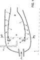
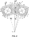
- annular combustion chamber 1 of a turbomachine With reference jointly to figures 1 and 2 , there is shown an annular combustion chamber 1 of a turbomachine, according to a preferred embodiment of the present invention.
- the combustion chamber 1 comprises an external axial wall 2, as well as an internal axial wall 4, these two walls 2 and 4 being disposed coaxially along a principal longitudinal axis 6 of the chamber 1, this axis 6 also corresponding to the axis longitudinal main of the turbomachine.
- the axial walls 2 and 4 are connected to each other via a chamber bottom 8, the latter being assembled for example by welding to an upstream portion of each of the axial walls 2 and 4.
- the chamber bottom 8 preferably takes the form of a substantially flat annular ring, of axis identical to the longitudinal main axis 6 of the chamber 1.
- this chamber bottom 8 could also have any other suitable shapes, such as a frustoconical shape of the same axis, without departing from the scope of the invention.
- Each of these injection orifices 10 is designed so as to be able to cooperate with a fuel injector 12, in order to allow the combustion reactions inside this combustion chamber 1.
- these injectors 12 are also designed to so as to allow the introduction of at least a portion of the air for combustion, the latter occurring in a primary zone 14 located in an upstream portion of the combustion chamber 1.
- the air for combustion can also be introduced inside the chamber 1 via primary orifices 16, located all around the external axial walls 2 and internal 4.
- the primary orifices 16 are arranged upstream of a plurality of dilution orifices 18, the latter also being placed all around the external axial walls 2 and internal walls 4, and whose main function is to allow the supply of air to a dilution zone 20 located downstream of the primary zone 14.
- a cooling air flow D serving mainly to cool the inner surface 21 of the chamber floor 8.
- an additional cooling air flow rate (not shown) is generally allocated to cool all of these interior hot surfaces 22 and 24.
- the chamber bottom 8 is of the multi-perforated type, namely that it has a plurality of perforations 26, preferably cylindrical of circular sections, and intended to allow the passage of the cooling air flow D inside the combustion chamber 1.
- the bottom chamber 8 is divided into an outer portion 28 connected to the outer axial wall 2, and an inner portion 30 connected to the inner axial wall 4.
- these annular portions 28 and 30 are usually formed in one piece, and their virtual separation may then consist of a center circle C located on the longitudinal main axis 6, and radius R corresponding to a mean radius between an outer radius and an inner radius from the bedroom floor 8.
- the perforations 26 located on the outer portion 28 are then made to direct a portion D1 of the cooling air flow D towards the outer axial wall 2, in order to cool the entire this outer portion 28, and an upstream portion of the outer axial wall 2.
- the perforations 26 on the inner portion 30 are made to direct another portion D2 of the cooling air flow D in the direction of the inner axial wall 4, in order to cool all of this inner portion 30, as well as an upstream portion of the inner axial wall 4.
- the perforations 26 of the outer portion 28 are such that the value of the acute angles A formed between a line substantially median 32 of the half-section and principal directions 34 of the perforations 26 in this half-section, evolves decreasingly as a function of the distance between these perforations 26 and this substantially median line 32.
- a substantially median line 32 of the half-section it is naturally to understand that it is the virtual line located approximately equal distance from the upstream portions of the external axial walls 2 and internal 4 considered in half-section, this line 32 can also be noted in that in addition to forming an axis of symmetry of the half-section shown, it virtually separates the outer portions 28 and inner 30 of the chamber bottom 8.
- this substantially median line 32, passing through the circle C, is also substantially perpendicular to the chamber bottom 8, insofar as it itself is substantially perpendicular to the axial walls 2 and 4 .
- each main direction 34 of the perforations 26 correspond respectively to their main axes, in the sense that these perforations 26 are all traversed diametrically by the section plane.
- each main direction 34 can then be considered as being a line substantially parallel to the two line segments symbolizing the perforation 26 concerned.
- the perforations 26 located near the substantially median line 32 can therefore be strongly inclined, for example so that the acute angle A reaches a value of about 60 °.
- the cooling air coming from these perforations 26 can therefore flow easily and directly along the inner surface 21 of the outer portion 28 of the chamber bottom 8, substantially radially to the outer axial wall 2, without disturbing combustion reactions in the primary zone 14.
- the perforations 26 located near the outer axial wall 2 may be inclined only slightly towards the wall 2, for example so that the acute angle A reaches a value of about 5 °.
- the cooling air coming from these perforations 26 can then easily and directly flow along the hot inner surface 22 of the external axial wall 2, without stagnating at the junction between the chamber bottom 8 and this same wall. axial 2.
- the perforations 26 of the inner portion 30 are such that the value of the acute angles B formed between the substantially median line 32 and principal directions 36 of the perforations 26 in this half-section, changes in a decreasing manner as a function of the distance between these perforations 26 and this substantially median line 32.
- the value of the acute angles B formed between on the one hand the main directions 36 of the perforations 26 of the inner portion 30, and on the other hand the line substantially median 32 can progressively evolve from about 60 ° to about 5 °, approaching the inner axial wall 4.
- the chamber bottom 8 is provided with primary sectors 38 of perforations 26, these primary sectors 38 being situated substantially between two directly consecutive injection orifices 10.
- the perforations 26 of each primary sector 38 are arranged to define rows in the form of curved lines centered on the center of the injection port 10 near which these perforations 26 are located.
- the chamber bottom 8 is also provided with secondary sectors 40 of perforations 26, these secondary sectors 40 being each between two consecutive primary sectors 38, on either side of an injection orifice 10 in one direction. substantially radial of the combustion chamber 1.
- a secondary sector 40 is both above and below the injection port 10 concerned.
- the perforations 26 of the outer portion 28 are such that the value of acute angles C formed between a substantially median line 42 of the half-section and principal directions 44 of the perforations 26 in this half-section, evolves in a decreasing manner as a function of the distance between these perforations 26 and this substantially median line 42.
- the perforations 26 of the inner portion 28 are such that the value of the acute angles D formed between the substantially median line 42 of the half-section and directions main 46 perforations 26 in this half-section, evolves decreasingly depending on the distance between these perforations 26 and this substantially median line 42.
- the perforations 26 of the secondary sectors 38 are preferably of greater dimensions than those of the perforations 26 of the primary sectors 40, because of their presence. in a lower number.
Landscapes
- Engineering & Computer Science (AREA)
- Chemical & Material Sciences (AREA)
- Combustion & Propulsion (AREA)
- Mechanical Engineering (AREA)
- General Engineering & Computer Science (AREA)
- Combustion Methods Of Internal-Combustion Engines (AREA)
- Fuel-Injection Apparatus (AREA)
- Turbine Rotor Nozzle Sealing (AREA)
- Cylinder Crankcases Of Internal Combustion Engines (AREA)
Applications Claiming Priority (2)
| Application Number | Priority Date | Filing Date | Title |
|---|---|---|---|
| FR0350232A FR2856467B1 (fr) | 2003-06-18 | 2003-06-18 | Chambre de combustion annulaire de turbomachine |
| PCT/FR2004/050281 WO2004113794A1 (fr) | 2003-06-18 | 2004-06-18 | Chambre de combustion annulaire de turbomachine |
Publications (2)
| Publication Number | Publication Date |
|---|---|
| EP1634021A1 EP1634021A1 (fr) | 2006-03-15 |
| EP1634021B1 true EP1634021B1 (fr) | 2018-08-29 |
Family
ID=33484726
Family Applications (1)
| Application Number | Title | Priority Date | Filing Date |
|---|---|---|---|
| EP04767843.8A Expired - Lifetime EP1634021B1 (fr) | 2003-06-18 | 2004-06-18 | Chambre de combustion annulaire de turbomachine |
Country Status (8)
| Country | Link |
|---|---|
| US (1) | US7328582B2 (ru) |
| EP (1) | EP1634021B1 (ru) |
| JP (1) | JP2006527834A (ru) |
| KR (1) | KR20060029203A (ru) |
| CN (1) | CN1701203A (ru) |
| FR (1) | FR2856467B1 (ru) |
| RU (1) | RU2351849C2 (ru) |
| WO (1) | WO2004113794A1 (ru) |
Families Citing this family (17)
| Publication number | Priority date | Publication date | Assignee | Title |
|---|---|---|---|---|
| FR2881813B1 (fr) * | 2005-02-09 | 2011-04-08 | Snecma Moteurs | Carenage de chambre de combustion de turbomachine |
| US7540152B2 (en) * | 2006-02-27 | 2009-06-02 | Mitsubishi Heavy Industries, Ltd. | Combustor |
| US7654091B2 (en) * | 2006-08-30 | 2010-02-02 | General Electric Company | Method and apparatus for cooling gas turbine engine combustors |
| US8438853B2 (en) * | 2008-01-29 | 2013-05-14 | Alstom Technology Ltd. | Combustor end cap assembly |
| US8763399B2 (en) * | 2009-04-03 | 2014-07-01 | Hitachi, Ltd. | Combustor having modified spacing of air blowholes in an air blowhole plate |
| FR2948988B1 (fr) | 2009-08-04 | 2011-12-09 | Snecma | Chambre de combustion de turbomachine comprenant des orifices d'entree d'air ameliores |
| FR2958013B1 (fr) * | 2010-03-26 | 2014-06-20 | Snecma | Chambre de combustion de turbomachine a compresseur centrifuge sans deflecteur |
| FR2964725B1 (fr) * | 2010-09-14 | 2012-10-12 | Snecma | Carenage aerodynamique pour fond de chambre de combustion |
| FR2980554B1 (fr) * | 2011-09-27 | 2013-09-27 | Snecma | Chambre annulaire de combustion d'une turbomachine |
| US9377198B2 (en) * | 2012-01-31 | 2016-06-28 | United Technologies Corporation | Heat shield for a combustor |
| FR3011317B1 (fr) * | 2013-10-01 | 2018-02-23 | Safran Aircraft Engines | Chambre de combustion pour turbomachine a admission d'air homogene au travers de systemes d'injection |
| US10267521B2 (en) | 2015-04-13 | 2019-04-23 | Pratt & Whitney Canada Corp. | Combustor heat shield |
| FR3042023B1 (fr) * | 2015-10-06 | 2020-06-05 | Safran Helicopter Engines | Chambre de combustion annulaire pour turbomachine |
| US10808929B2 (en) * | 2016-07-27 | 2020-10-20 | Honda Motor Co., Ltd. | Structure for cooling gas turbine engine |
| FR3070751B1 (fr) * | 2017-09-01 | 2022-05-27 | Safran Aircraft Engines | Chambre de combustion comportant une repartition amelioree de trous de refroidissement |
| US11313560B2 (en) | 2018-07-18 | 2022-04-26 | General Electric Company | Combustor assembly for a heat engine |
| US20240200778A1 (en) * | 2022-12-20 | 2024-06-20 | General Electric Company | Gas turbine engine combustor with a set of dilution passages |
Family Cites Families (9)
| Publication number | Priority date | Publication date | Assignee | Title |
|---|---|---|---|---|
| US5307637A (en) * | 1992-07-09 | 1994-05-03 | General Electric Company | Angled multi-hole film cooled single wall combustor dome plate |
| DE19502328A1 (de) * | 1995-01-26 | 1996-08-01 | Bmw Rolls Royce Gmbh | Hitzeschild für eine Gasturbinen-Brennkammer |
| FR2733582B1 (fr) * | 1995-04-26 | 1997-06-06 | Snecma | Chambre de combustion comportant une multiperforation d'inclinaison axiale et tangentielle variable |
| FR2751731B1 (fr) * | 1996-07-25 | 1998-09-04 | Snecma | Ensemble bol-deflecteur pour chambre de combustion de turbomachine |
| US6155056A (en) * | 1998-06-04 | 2000-12-05 | Pratt & Whitney Canada Corp. | Cooling louver for annular gas turbine engine combustion chamber |
| US6145319A (en) * | 1998-07-16 | 2000-11-14 | General Electric Company | Transitional multihole combustion liner |
| US6546733B2 (en) * | 2001-06-28 | 2003-04-15 | General Electric Company | Methods and systems for cooling gas turbine engine combustors |
| DE10158548A1 (de) * | 2001-11-29 | 2003-06-12 | Rolls Royce Deutschland | Brennkammerschindel für eine Gasturbine mit mehreren Kühllöchern mit unterschiedlicher Winkelausrichtung |
| US6751961B2 (en) * | 2002-05-14 | 2004-06-22 | United Technologies Corporation | Bulkhead panel for use in a combustion chamber of a gas turbine engine |
-
2003
- 2003-06-18 FR FR0350232A patent/FR2856467B1/fr not_active Expired - Lifetime
-
2004
- 2004-06-18 JP JP2006516352A patent/JP2006527834A/ja active Pending
- 2004-06-18 EP EP04767843.8A patent/EP1634021B1/fr not_active Expired - Lifetime
- 2004-06-18 RU RU2005107793/06A patent/RU2351849C2/ru active
- 2004-06-18 CN CNA2004800009068A patent/CN1701203A/zh active Pending
- 2004-06-18 WO PCT/FR2004/050281 patent/WO2004113794A1/fr active Application Filing
- 2004-06-18 KR KR1020057010887A patent/KR20060029203A/ko not_active Application Discontinuation
- 2004-06-18 US US10/529,583 patent/US7328582B2/en active Active
Also Published As
| Publication number | Publication date |
|---|---|
| RU2351849C2 (ru) | 2009-04-10 |
| FR2856467B1 (fr) | 2005-09-02 |
| FR2856467A1 (fr) | 2004-12-24 |
| WO2004113794A1 (fr) | 2004-12-29 |
| US7328582B2 (en) | 2008-02-12 |
| CN1701203A (zh) | 2005-11-23 |
| EP1634021A1 (fr) | 2006-03-15 |
| KR20060029203A (ko) | 2006-04-05 |
| JP2006527834A (ja) | 2006-12-07 |
| US20070056289A1 (en) | 2007-03-15 |
| RU2005107793A (ru) | 2005-11-20 |
Similar Documents
| Publication | Publication Date | Title |
|---|---|---|
| EP1634021B1 (fr) | Chambre de combustion annulaire de turbomachine | |
| EP1777458B1 (fr) | Amélioration des performances d'une chambre de combustion par multiperforation des parois | |
| EP2771618B1 (fr) | Paroi annulaire de chambre de combustion à refroidissement amélioré au niveau des trous primaires et/ou de dilution | |
| EP2026002B1 (fr) | Injecteur multipoint pour turbomachine | |
| EP1849986B1 (fr) | Turboréacteur comprenant un canal de post combustion refroidi par un flux de ventilation a débit variable | |
| CA2891072C (fr) | Support de tube d'evacuation d'air dans une turbomachine | |
| EP2524169B1 (fr) | Chambre de combustion multi-percee a ecoulements tangentiels contre giratoires | |
| EP1489359B1 (fr) | Chambre de combustion annulaire de turbomachine | |
| EP2042806A1 (fr) | Chambre de combustion d'une turbomachine | |
| CA2848629C (fr) | Chambre annulaire de combustion d'une turbomachine | |
| FR2968030A1 (fr) | Turbine basse-pression de turbomachine d'aeronef, comprenant un distributeur sectorise de conception amelioree | |
| EP2683930B1 (fr) | Injecteur pour le mélange de deux ergols comprenant au moins un élément d'injection a structure tricoaxiale | |
| CA2754419C (fr) | Chambre de combustion de turbomachine comprenant des moyens ameliores d'alimentation en air | |
| CA2891076C (fr) | Support de tube d'evacuation d'air dans une turbomachine | |
| WO2015049438A2 (fr) | Injecteur de carburant dans une turbomachine | |
| EP4136327B1 (fr) | Dispositif de refroidissement d'un carter de turbine | |
| WO2018050999A1 (fr) | Chambre de combustion pour turbomachine comprenant des moyens pour améliorer le refroidissement d'une paroi annulaire dans le sillage d'un obstacle | |
| FR2594939A1 (fr) | Structure d'accroche-flamme pour systeme de rechauffe de turboreacteur | |
| EP4042070B1 (fr) | Canne de prévaporisation pour une chambre de combustion de turbomachine | |
| WO2022096832A1 (fr) | Fixation d'un cône d'éjection dans une turbine de turbomachine | |
| FR3088412A1 (fr) | Chambre de combustion de turbomachine, turbomachine associee | |
| CA3110912A1 (fr) | Boitier d'alimentation en air sous pression d'un dispositif de refroidissement par jets d'air | |
| FR2711209A1 (fr) | Dispositif de solidarisation de conteneurs et conteneur associé à un tel dispositif. | |
| WO2014053760A1 (fr) | Fond de chambre annulaire pour chambre de combustion de turbomachine d'aeronef, muni de perforations permettant un refroidissement par flux giratoire | |
| FR3070751A1 (fr) | Chambre de combustion comportant une repartition amelioree de trous de refroidissement |
Legal Events
| Date | Code | Title | Description |
|---|---|---|---|
| PUAI | Public reference made under article 153(3) epc to a published international application that has entered the european phase |
Free format text: ORIGINAL CODE: 0009012 |
|
| 17P | Request for examination filed |
Effective date: 20050302 |
|
| AK | Designated contracting states |
Kind code of ref document: A1 Designated state(s): AT BE BG CH CY CZ DE DK EE ES FI FR GB GR HU IE IT LI LU MC NL PL PT RO SE SI SK TR |
|
| DAX | Request for extension of the european patent (deleted) | ||
| RIN1 | Information on inventor provided before grant (corrected) |
Inventor name: SALAN, YVES Inventor name: SANDELIS, DENIS |
|
| 17Q | First examination report despatched |
Effective date: 20160303 |
|
| GRAP | Despatch of communication of intention to grant a patent |
Free format text: ORIGINAL CODE: EPIDOSNIGR1 |
|
| STAA | Information on the status of an ep patent application or granted ep patent |
Free format text: STATUS: GRANT OF PATENT IS INTENDED |
|
| INTG | Intention to grant announced |
Effective date: 20180308 |
|
| GRAS | Grant fee paid |
Free format text: ORIGINAL CODE: EPIDOSNIGR3 |
|
| RAP1 | Party data changed (applicant data changed or rights of an application transferred) |
Owner name: SAFRAN AIRCRAFT ENGINES |
|
| GRAA | (expected) grant |
Free format text: ORIGINAL CODE: 0009210 |
|
| STAA | Information on the status of an ep patent application or granted ep patent |
Free format text: STATUS: THE PATENT HAS BEEN GRANTED |
|
| AK | Designated contracting states |
Kind code of ref document: B1 Designated state(s): AT BE BG CH CY CZ DE DK EE ES FI FR GB GR HU IE IT LI LU MC NL PL PT RO SE SI SK TR |
|
| REG | Reference to a national code |
Ref country code: GB Ref legal event code: FG4D Free format text: NOT ENGLISH |
|
| REG | Reference to a national code |
Ref country code: CH Ref legal event code: EP |
|
| REG | Reference to a national code |
Ref country code: AT Ref legal event code: REF Ref document number: 1035566 Country of ref document: AT Kind code of ref document: T Effective date: 20180915 |
|
| REG | Reference to a national code |
Ref country code: IE Ref legal event code: FG4D Free format text: LANGUAGE OF EP DOCUMENT: FRENCH |
|
| REG | Reference to a national code |
Ref country code: DE Ref legal event code: R096 Ref document number: 602004053119 Country of ref document: DE |
|
| REG | Reference to a national code |
Ref country code: SE Ref legal event code: TRGR |
|
| REG | Reference to a national code |
Ref country code: NL Ref legal event code: MP Effective date: 20180829 |
|
| PG25 | Lapsed in a contracting state [announced via postgrant information from national office to epo] |
Ref country code: BG Free format text: LAPSE BECAUSE OF FAILURE TO SUBMIT A TRANSLATION OF THE DESCRIPTION OR TO PAY THE FEE WITHIN THE PRESCRIBED TIME-LIMIT Effective date: 20181129 Ref country code: NL Free format text: LAPSE BECAUSE OF FAILURE TO SUBMIT A TRANSLATION OF THE DESCRIPTION OR TO PAY THE FEE WITHIN THE PRESCRIBED TIME-LIMIT Effective date: 20180829 Ref country code: GR Free format text: LAPSE BECAUSE OF FAILURE TO SUBMIT A TRANSLATION OF THE DESCRIPTION OR TO PAY THE FEE WITHIN THE PRESCRIBED TIME-LIMIT Effective date: 20181130 Ref country code: FI Free format text: LAPSE BECAUSE OF FAILURE TO SUBMIT A TRANSLATION OF THE DESCRIPTION OR TO PAY THE FEE WITHIN THE PRESCRIBED TIME-LIMIT Effective date: 20180829 |
|
| REG | Reference to a national code |
Ref country code: AT Ref legal event code: MK05 Ref document number: 1035566 Country of ref document: AT Kind code of ref document: T Effective date: 20180829 |
|
| PG25 | Lapsed in a contracting state [announced via postgrant information from national office to epo] |
Ref country code: ES Free format text: LAPSE BECAUSE OF FAILURE TO SUBMIT A TRANSLATION OF THE DESCRIPTION OR TO PAY THE FEE WITHIN THE PRESCRIBED TIME-LIMIT Effective date: 20180829 |
|
| PG25 | Lapsed in a contracting state [announced via postgrant information from national office to epo] |
Ref country code: EE Free format text: LAPSE BECAUSE OF FAILURE TO SUBMIT A TRANSLATION OF THE DESCRIPTION OR TO PAY THE FEE WITHIN THE PRESCRIBED TIME-LIMIT Effective date: 20180829 Ref country code: PL Free format text: LAPSE BECAUSE OF FAILURE TO SUBMIT A TRANSLATION OF THE DESCRIPTION OR TO PAY THE FEE WITHIN THE PRESCRIBED TIME-LIMIT Effective date: 20180829 Ref country code: CZ Free format text: LAPSE BECAUSE OF FAILURE TO SUBMIT A TRANSLATION OF THE DESCRIPTION OR TO PAY THE FEE WITHIN THE PRESCRIBED TIME-LIMIT Effective date: 20180829 Ref country code: AT Free format text: LAPSE BECAUSE OF FAILURE TO SUBMIT A TRANSLATION OF THE DESCRIPTION OR TO PAY THE FEE WITHIN THE PRESCRIBED TIME-LIMIT Effective date: 20180829 Ref country code: RO Free format text: LAPSE BECAUSE OF FAILURE TO SUBMIT A TRANSLATION OF THE DESCRIPTION OR TO PAY THE FEE WITHIN THE PRESCRIBED TIME-LIMIT Effective date: 20180829 |
|
| PG25 | Lapsed in a contracting state [announced via postgrant information from national office to epo] |
Ref country code: SK Free format text: LAPSE BECAUSE OF FAILURE TO SUBMIT A TRANSLATION OF THE DESCRIPTION OR TO PAY THE FEE WITHIN THE PRESCRIBED TIME-LIMIT Effective date: 20180829 Ref country code: DK Free format text: LAPSE BECAUSE OF FAILURE TO SUBMIT A TRANSLATION OF THE DESCRIPTION OR TO PAY THE FEE WITHIN THE PRESCRIBED TIME-LIMIT Effective date: 20180829 |
|
| REG | Reference to a national code |
Ref country code: DE Ref legal event code: R097 Ref document number: 602004053119 Country of ref document: DE |
|
| PLBE | No opposition filed within time limit |
Free format text: ORIGINAL CODE: 0009261 |
|
| STAA | Information on the status of an ep patent application or granted ep patent |
Free format text: STATUS: NO OPPOSITION FILED WITHIN TIME LIMIT |
|
| 26N | No opposition filed |
Effective date: 20190531 |
|
| PG25 | Lapsed in a contracting state [announced via postgrant information from national office to epo] |
Ref country code: SI Free format text: LAPSE BECAUSE OF FAILURE TO SUBMIT A TRANSLATION OF THE DESCRIPTION OR TO PAY THE FEE WITHIN THE PRESCRIBED TIME-LIMIT Effective date: 20180829 |
|
| PG25 | Lapsed in a contracting state [announced via postgrant information from national office to epo] |
Ref country code: MC Free format text: LAPSE BECAUSE OF FAILURE TO SUBMIT A TRANSLATION OF THE DESCRIPTION OR TO PAY THE FEE WITHIN THE PRESCRIBED TIME-LIMIT Effective date: 20180829 |
|
| REG | Reference to a national code |
Ref country code: CH Ref legal event code: PL |
|
| REG | Reference to a national code |
Ref country code: BE Ref legal event code: MM Effective date: 20190630 |
|
| PG25 | Lapsed in a contracting state [announced via postgrant information from national office to epo] |
Ref country code: TR Free format text: LAPSE BECAUSE OF FAILURE TO SUBMIT A TRANSLATION OF THE DESCRIPTION OR TO PAY THE FEE WITHIN THE PRESCRIBED TIME-LIMIT Effective date: 20180829 |
|
| PG25 | Lapsed in a contracting state [announced via postgrant information from national office to epo] |
Ref country code: IE Free format text: LAPSE BECAUSE OF NON-PAYMENT OF DUE FEES Effective date: 20190618 |
|
| PG25 | Lapsed in a contracting state [announced via postgrant information from national office to epo] |
Ref country code: CH Free format text: LAPSE BECAUSE OF NON-PAYMENT OF DUE FEES Effective date: 20190630 Ref country code: BE Free format text: LAPSE BECAUSE OF NON-PAYMENT OF DUE FEES Effective date: 20190630 Ref country code: LI Free format text: LAPSE BECAUSE OF NON-PAYMENT OF DUE FEES Effective date: 20190630 Ref country code: LU Free format text: LAPSE BECAUSE OF NON-PAYMENT OF DUE FEES Effective date: 20190618 |
|
| PG25 | Lapsed in a contracting state [announced via postgrant information from national office to epo] |
Ref country code: PT Free format text: LAPSE BECAUSE OF FAILURE TO SUBMIT A TRANSLATION OF THE DESCRIPTION OR TO PAY THE FEE WITHIN THE PRESCRIBED TIME-LIMIT Effective date: 20181229 |
|
| PG25 | Lapsed in a contracting state [announced via postgrant information from national office to epo] |
Ref country code: CY Free format text: LAPSE BECAUSE OF FAILURE TO SUBMIT A TRANSLATION OF THE DESCRIPTION OR TO PAY THE FEE WITHIN THE PRESCRIBED TIME-LIMIT Effective date: 20180829 |
|
| PG25 | Lapsed in a contracting state [announced via postgrant information from national office to epo] |
Ref country code: HU Free format text: LAPSE BECAUSE OF FAILURE TO SUBMIT A TRANSLATION OF THE DESCRIPTION OR TO PAY THE FEE WITHIN THE PRESCRIBED TIME-LIMIT; INVALID AB INITIO Effective date: 20040618 |
|
| PGFP | Annual fee paid to national office [announced via postgrant information from national office to epo] |
Ref country code: IT Payment date: 20230523 Year of fee payment: 20 Ref country code: FR Payment date: 20230523 Year of fee payment: 20 Ref country code: DE Payment date: 20230523 Year of fee payment: 20 |
|
| PGFP | Annual fee paid to national office [announced via postgrant information from national office to epo] |
Ref country code: SE Payment date: 20230523 Year of fee payment: 20 |
|
| PGFP | Annual fee paid to national office [announced via postgrant information from national office to epo] |
Ref country code: GB Payment date: 20230523 Year of fee payment: 20 |
|
| REG | Reference to a national code |
Ref country code: DE Ref legal event code: R071 Ref document number: 602004053119 Country of ref document: DE |
|
| PG25 | Lapsed in a contracting state [announced via postgrant information from national office to epo] |
Ref country code: GB Free format text: LAPSE BECAUSE OF EXPIRATION OF PROTECTION Effective date: 20240617 |
|
| REG | Reference to a national code |
Ref country code: SE Ref legal event code: EUG |
|
| PG25 | Lapsed in a contracting state [announced via postgrant information from national office to epo] |
Ref country code: GB Free format text: LAPSE BECAUSE OF EXPIRATION OF PROTECTION Effective date: 20240617 |