EP1633035B1 - Method of winding an electric coil for an electrical machine - Google Patents
Method of winding an electric coil for an electrical machine Download PDFInfo
- Publication number
- EP1633035B1 EP1633035B1 EP20050107450 EP05107450A EP1633035B1 EP 1633035 B1 EP1633035 B1 EP 1633035B1 EP 20050107450 EP20050107450 EP 20050107450 EP 05107450 A EP05107450 A EP 05107450A EP 1633035 B1 EP1633035 B1 EP 1633035B1
- Authority
- EP
- European Patent Office
- Prior art keywords
- winding
- tooth
- wire
- mask
- channel
- Prior art date
- Legal status (The legal status is an assumption and is not a legal conclusion. Google has not performed a legal analysis and makes no representation as to the accuracy of the status listed.)
- Not-in-force
Links
Images


Classifications
-
- H—ELECTRICITY
- H02—GENERATION; CONVERSION OR DISTRIBUTION OF ELECTRIC POWER
- H02K—DYNAMO-ELECTRIC MACHINES
- H02K3/00—Details of windings
- H02K3/46—Fastening of windings on the stator or rotor structure
- H02K3/52—Fastening salient pole windings or connections thereto
- H02K3/521—Fastening salient pole windings or connections thereto applicable to stators only
- H02K3/522—Fastening salient pole windings or connections thereto applicable to stators only for generally annular cores with salient poles
-
- H—ELECTRICITY
- H02—GENERATION; CONVERSION OR DISTRIBUTION OF ELECTRIC POWER
- H02K—DYNAMO-ELECTRIC MACHINES
- H02K15/00—Methods or apparatus specially adapted for manufacturing, assembling, maintaining or repairing of dynamo-electric machines
- H02K15/08—Forming windings by laying conductors into or around core parts
- H02K15/095—Forming windings by laying conductors into or around core parts by laying conductors around salient poles
-
- H—ELECTRICITY
- H02—GENERATION; CONVERSION OR DISTRIBUTION OF ELECTRIC POWER
- H02K—DYNAMO-ELECTRIC MACHINES
- H02K3/00—Details of windings
- H02K3/04—Windings characterised by the conductor shape, form or construction, e.g. with bar conductors
- H02K3/18—Windings for salient poles
-
- H—ELECTRICITY
- H02—GENERATION; CONVERSION OR DISTRIBUTION OF ELECTRIC POWER
- H02K—DYNAMO-ELECTRIC MACHINES
- H02K2203/00—Specific aspects not provided for in the other groups of this subclass relating to the windings
- H02K2203/12—Machines characterised by the bobbins for supporting the windings
Definitions
- the invention is based on a method for winding an electrical winding from a winding wire onto a magnetically conductive body of a main element, such as stator or rotor, of an electrical machine, according to the preamble of claim 1.
- a bobbin or bobbin of electrically insulating material having a double-T-shaped longitudinal profile with an arcuate long transverse leg, an arcuate short transverse leg and the two transverse legs together integrally connecting, hollow box-shaped longitudinal web, pushed with the hollow longitudinal web on a winding tool ,
- the beginning of the winding wire preferably an insulated copper wire, set, and by rotation of the winding tool, which also performs an axial reciprocating motion, the winding wire is wound on the longitudinal web of the bobbin to form an annular coil, which is supported on the two transverse legs.
- the end of the winding wire is attached to the bobbin.
- the coil carrier with coiled-up ring coil is pulled off the tool carrier and pushed onto a tooth with a T-profile.
- the individual teeth carrying the annular coils with coil carriers are joined by means of a dovetail connection into the return ring of the stator body.
- Such a winding method is not suitable for wrapping a winding also consisting of toroidal coils in a stator or rotor body, in which yoke or ring and teeth with toothed shaft and tooth shoe are formed integrally with each other and the e.g. is axially packaged from a plurality of adjacent laminations, wherein each lamination is formed as a complete blank.
- FIG. 13 A known method for winding an electrical winding on such a stator body of an internal rotor motor is in Fig. 13 illustrated in four sketches.
- the stator body 11 with return ring 12 and stator teeth 13, each having a radially projecting from the return ring 12 toothed shaft 131 and an integrally formed on remind gleichringen end of the toothed shaft 131 tooth head or tooth shoe 132 have only partially shown.
- the stator teeth 11 axially extending, frontally open grooves 14 are formed in the stator body, the groove bottom is formed by the return ring and their slot opening covered by toothed shoes adjacent stator teeth to a groove gap 15 is.
- such a stator body 11 is wound with a stator winding having wound on the stator teeth 13 ring coils whose coil sides eino in the grooves 14 and connecting the coil sides, arcuate coil heads extend over the end faces of the tooth shafts 131.
- the toothed shoes 132 secure the coils against radial slippage.
- the coils are wound in a winding machine from a winding wire 16 in several winding layers.
- the winding wire 16 preferably an insulated copper wire, drawn off from a supply winding is fed to a wire guiding device 17, which draws the winding wire 16 into the stator body 11 clamped in the winding machine.
- the wire guiding device 17 consists of an axially aligned needle 18 arranged in the hollow interior of the stator body 11 and a nozzle 19 projecting radially from the needle 18 with a wire extension end 191 from which the winding wire 16 emerges.
- the nozzle 19 of the needle 18 protrudes through the groove gap 15 into the groove 14 and performs an axial movement from bottom to top, wherein it emerges after covering the maximum stroke of the needle 18 on the front side of the groove 14.
- the case pulled out of the Drahtaus istde 191 wire section lies in the groove 14, for example, on the groove bottom, a ( Fig. 13a ).
- the stator body 11 is rotated about a stator tooth 13 ( Fig. 13b ), so that the Nozzle 19 is located above the end face of the next groove 14 '( Fig. 13c ).
- the nozzle 19 is displaced downwardly in the adjacent groove 14 ', with the nozzle 19 sliding in the groove gap 15.
- the winding wire 16 is placed over the end face of the stator tooth 13 and, on the other hand, another section of the winding wire 16 is drawn into the adjacent groove 14 '. If the needle 18 has reached its lower maximum stroke position, the nozzle 19 has emerged from the end face of the groove 14 ( Fig. 13d ). Now, the stator body 11 is rotated back by the same tooth pitch, and the needle 18 again performs a lifting movement from above ( Fig. 13a ), wherein a second winding wire section 16 is inserted into the first groove 14. If the needle 18 has reached its upper maximum stroke position ( Fig.
- stator body 11 is rotated in the same direction as before by a tooth pitch and the lifting needle in turn performs a lifting movement to its lower end position. Thereafter, the stator body 11 is again rotated back by one tooth step. The processes described are repeated until the desired number of turns of the toroidal coil is wound onto the stator tooth 13. Thereafter, the stator body 11 is rotated so far that the nozzle 19 is above one of the two grooves bounded by the stator tooth, which must be wound next. In this winding technique, it is important that the travel for the nozzle 19 is kept within the grooves; because a wire section located in the travel path of the nozzle 19 can be damaged by the nozzle 19, which leads to winding or grounding of the winding.
- a known DC motor ( DE 198 18 432 A1 ) has a magnetically conductive stator core with return ring and molded, radially projecting, each having a toothed shaft and a toothed tooth forming between axially extending frontally open grooves, and a stator core covering mask on which the electrical winding of the DC motor in shape is wound by spools.
- the mask has a dental cladding covering the longitudinal and end sides of the dental stems and a groove base covering covering the groove bases forming the return yoke ring.
- Immediately to the groove base clothing is one with the dental cladding circumferential step integrally formed with tooth cover and groove base. At the free, inner end of each tooth lining a circumferential flange is formed.
- the mask is divided axially into two equally formed half, one half of which is placed from below and the other half from above on the stator body, so that each of the circumferential flanges in the upper and lower half of the mask has a U-shape.
- the wire guiding device is displaced only axially along the respective stator tooth and pivoted above and below the end faces of the stator tooth in order to pull the winding wire over the end faces of the stator teeth covered by the mask.
- the winding needle performs at no time a radial movement, but remains constant either in the front part of the grooves formed between the stator teeth or in the slot opening between the tooth or pole pieces of adjacent stator teeth.
- the mask is provided with a winding aid.
- This winding aid has a plurality of inserts of electrical insulation material, as resting on the mask in the region of the end faces of the stator teeth between the two flanges.
- Each insert has a circular segment-shaped cross-section whose segment width corresponds approximately to the width of the mask in the region of the end faces of the stator teeth and whose segment height is reduced in the radial direction, maximum on the inner flange and minimal on the outer flange.
- the inner and outer flange associated, axially projecting pins are provided, around which the winding wire is guided before it is retracted into the grooves.
- the inventive method with the features of claim 1 has the advantage that by the use of the mask of electrically insulating material, which is placed on the latter for the isolation of the magnetically conductive body and the formation of this mask as a winding aid when wrapping the winding wire of the winding wire in the Grooves can be guided and positioned very precisely, so that on the one hand the travel for the nozzle can be kept reliably - and thus no damage to the winding wire can occur - and on the other hand by accurate placement of the winding wire in the grooves of the available groove space better is exploited, so that an improvement of the slot fill factor is achieved.
- the Drahtaus By the control of the wire guide device, the Drahtaus convincedde the wire guide device immersed at no time of the winding process in the groove space, so that in the groove space no travel the Drahtaus istde must be kept free and the groove space can be completely wound.
- the desired placement of each retracted winding wire section is ensured by the gradations on the front sides of the mask, is pulled over each of which in carrying out a relative rotation of Drahtaus istde and body of the winding wire.
- the mask is provided at one end with a cross-sectionally U-shaped laying channel with two channel walls and a channel bottom whose one channel wall covers the return ring and the other channel wall and the channel bottom are formed by spaced segments whose radial Center lines are aligned with the radial centerlines of the teeth.
- the contacting of the electrical winding is limited to the contacting of the individual winding strands, in a three-phase winding so on three contact point for each winding strand and possibly a contact point for the neutral point.
- This contacting is carried out by means of contact lugs, for which purpose, according to an advantageous embodiment of the invention, the contact lugs are inserted into selected, axially extending receiving shafts which are present in the segments on the one end side of the mask, and the winding wire is electrically connected to the contact lugs.
- a mask for producing an electrical insulation between the magnetically conductive body and an electrical winding wrapped therein, which is also used as a winding aid in the inventive method is given in the independent claim 5 and in dependent from claim 5 claims 6 to 12.
- the main element for an electric machine will be described below using the example of a stator of an internal rotor machine, e.g. a DC motor, described.
- the main element can also be a rotor of an external rotor machine in the same design, so that the terms stator stator used for the magnetically conductive body and stator winding for the electrical winding are also synonymous with the rotor body and rotor winding of an external rotor machine.
- the stator has a body, referred to as a stator body 21, of magnetically conductive material which, in a known manner, is made of a plurality of components into a stamped package assembled individual slats, and a stator winding 22 designated electrical winding on.
- the stator body 21 consists of a return ring 24 and a plurality of teeth 25 with toothed shaft 251 and tooth shoe 252.
- the teeth 25 are offset by equal circumferential angle to each other on the return ring 24, arranged radially inwardly projecting from this and wear at the free end of their tooth shafts 251 Toothed shoes 252.
- the teeth 25 enclose between them axially extending grooves 26 which widen to the groove base 261 formed by the return ring 24 and whose slot opening facing away from the groove base 261 from the toothed shoes 252 of the two teeth 25 each enclosing a groove 26 except for a slot gap 262 is closed.
- the stator winding 22 consists of interconnected coils 221, which are wound with a winding wire 27 relative to the stator 21 electrically insulated in several winding layers on the teeth 25 of the stator body 21 so that their axially extending coil sides eino in the grooves 26 and their arcuate coil ends cover the front sides of the tooth shafts 251.
- a mask 30 of electrically insulating material for example plastic, which is divided axially into two parts, preferably in half, and whose upper part is in Fig. 3 is shown in perspective.
- the lower part of the mask 30 is identical except for a detail to be explained later.
- the upper part of the mask 30 is from the one end side of the stator body 21 ago and the lower part of the mask 30 from the other Front side of the stator 21 ago pushed onto the stator body 21, so that they assemble to form a circumferential gap to the mask 30 together.
- the interface of the two mask parts is in Fig. 3 marked with 301.
- the mask 30 is designed so that it can be used in addition to its insulation function as a winding aid when wrapping the coils 221 of the stator winding 22 forming winding wire 27, which allows a subsequently described, advantageous winding method for the stator winding 22, which leads to a high Nutrachll tone ,
- the mask 30 produced as a plastic injection molded part has a tooth cover 31 for covering the side and end faces of the tooth shanks 251 and a groove base cover or groove base covering 32 for covering the groove base forming portions of the return ring 24.
- the groove base clothing 32 is integral with the tooth lining 31 and connects the individual forms of the tooth lining 31 to the individual teeth 25. As is apparent from the perspective view in FIG Fig. 3 and in particular from the sectional view of an expression of the tooth lining 31 for a tooth 25 in FIG Fig.
- each of the end faces of the tooth shafts 251 covering portions 311 of the tooth lining 31 is a radially extending step 33 with a step 331, one of the step 331 toward the groove base 32 subsequent, compared to the step 331 axially set back staggering section 332nd and a step edge 333 facing the groove base 32, which extends axially from the step portion 332 to the step 331.
- the height of the step edge 333 is sized slightly larger than the outer diameter of the winding wire 27, such as this from the fragmentary sectional view in 10 and 11 can be seen.
- the radial length of the staging section 332 and the step 331 are each an integer multiple of the outer diameter of the winding wire 27.
- the step 331 and the step section 332 are equal in length but may have a different multiple of the outside diameter of the coil wire 27.
- a holding flange 34 is integrally formed in each of the end faces of the tooth shanks 251 covering regions 311 of the tooth lining 31.
- the axial projection height of the retaining flange 34 is dimensioned according to the number of wound into the grooves 26 winding layers of the coils 221.
- the retaining flange 34 prevents slipping of winding layers or windings of the coils 221 of the stator winding 22.
- the steps 33 can have more than just one stage 331.
- the lower mask part of the mask 30 is formed in an identical manner as the upper mask part of the mask 30 described here.
- the upper mask part additionally has a laying aid for the winding wire 27 formed on its end face in order to connect the coils 221 Thus, to facilitate guiding the winding wire 27 from one coil 221 to the next coil 221 of the stator winding 22.
- a cross-sectionally U-shaped laying channel 35 with two channel walls and the channel walls interconnecting channel bottom provided with a radially outwardly facing opening over almost the entire Circumference of the mask 30 rotates.
- the one channel wall forms one Cover 36 for the end face of the hollow cylindrical return ring 22, and the other channel wall and the channel bottom are formed by longitudinally approximately L-shaped segments 37 which are spaced from each other arranged such that their radial symmetry or center lines with the center lines of the individual forms of Tooth 31 on the teeth 25 are aligned.
- the laying channel 35 is formed by seven of the total of nine existing segments 37 and ends at the two in Fig. 3 Alternatively, the laying channel 35 can also be passed through these two segments 37, so that it closes completely.
- an axial receiving shaft 38 is formed for insertion of contact lugs, not shown here.
- a receiving shaft 38 is in section in Fig. 4 to see.
- the contact lugs are used for electrical connection of the individual strands of the stator winding 22, which in the embodiment of the Fig. 1 consists of three winding strands, each with three within a winding strand by 120 ° electrically offset coils 221.
- stator winding 22 on the stator body 21 will be described below with reference to Fig. 5 to 11 explained.
- stator body 21 On the stator body 21, the two mask parts of the mask 30 are pushed axially from both end faces until the interfaces 301 of the two mask parts lie opposite each other with gap spacing.
- the stator body 21 can be overmolded with the mask 30 in the described embodiment, in which case the Gap between the mask parts is omitted.
- the stator body 21 provided with the mask 30 is inserted into a winding machine and can be rotated in the circumferential direction in both directions during winding by defined switching steps, which correspond in each case to a tooth pitch of the stator body 21.
- a wire guide device 40 In the hollow interior of the stator body 21, a wire guide device 40 is arranged so that it can perform an axial and radial stroke, each with respect to the stator body 21.
- the wire guide device 40 comprises a needle 41 which is displaceable in the axial direction and one of the needle 41st
- the needle 41 performs an axial stroke between a lower end position, in which the nozzle 42 is below the front side of the stator body 21, and an upper end position, in which the nozzle 42 above the upper end side of the stator 21 is located.
- the needle 41 is able to perform a radial lifting movement, by which the wire extension end 401 of the nozzle 42 pushes over the end faces of the axially open grooves 26 and retracts behind the toothed shoe circle 28 again.
- Fig. 5 to 9 the wire guide device 40 with needle 41 and nozzle 42 and the stator body 21 accommodated in the winding machine are only sketched schematically, wherein the mask 30 pushed onto the stator body 21 with tooth cover 31 and groove base 32 is shown in section for the sake of clarity.
- the winding wire 27, not shown here is withdrawn from a supply roll through the needle 41 and pulled out via the nozzle 42 from the Drahtaus istde 401.
- the wire guide device 40 is in its lower end position.
- the pulled-out from the Drahtaus istde 401 portion of the winding wire 27 is fixed to the upper end face of the mask 30 and pulled within the groove 26 down.
- the wire guide device 40 now performs a radial movement, wherein the wire extension end 401 sweeps over the lower end face of the groove 26 and the winding wire 27 places in the desired place ( Fig. 6 ).
- the stator body 21 is rotated clockwise by one tooth pitch, so that the wire extension end 401 of the wire guide device 40 is below the adjacent groove 26 * ( Fig. 7 ).
- the winding wire settles in the step 33 in the area 311 of the mask 30 covering the lower end face of the tooth 25.
- the wire guide device 40 now moves back radially to the extent that the wire pull-out end 401 comes to rest within the tooth shoe circle 28 of the stator body (FIG. Fig. 8 ). Thereafter, the wire guide device 40 performs a lifting movement in its upper end position and pushes here by a radial movement of the Drahtaus istde 401 over the upper end face of the groove 26 * to the winding wire is at the desired position.
- stator body 21 is rotated back by a pitch, with the winding wire in the step 33 in which the upper end face of the tooth shank 241 covering areas 311 of the mask 30 inserts ( Fig. 10 ).
- the wire guide device 40 is again displaced radially so that the wire pull-out end 401 retracts behind the toothed shoe circle 28 ( Fig. 9 ).
- a lifting movement of the wire guide device 40 in the lower end position, as shown in Fig. 5 shown is.
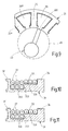
- Fig. 10 are in the course of the winding process in the gradation 33 inserted turns of the winding wire 27 with 1 to 9 numbered. How out Fig. 10 can be seen, while the first turn 1, which is wound around the tooth 25, retained upon retraction of Drahtaus convinceddes 401 behind the toothed shoe 28 at the step edge 333 and is not pulled out again through the groove gap 362 from the groove 26. Similarly, the next turn 2 hooks behind the first turn 1 located in the axially recessed staging section 332 and also the third turn 3 behind the second turn 2. The fourth turn 4 is placed on the step 331 and retracted from the retainer flange 34 upon retraction Wire extending 401 is retained behind the toothed shoe circle 28.
- the windings 5 and 6 are inserted, which rest on the stage 331 and are retained by the respective previous turn, and inserted the windings 7 to 9, which hang up on the previously wound winding layer with the windings 1, 2 and 3 and be retained by the winding 3 and the previously inserted turn 7 and 8.
- the stator body 21 is pivoted to the next tooth 25, which has to accommodate the next coil 221 belonging to the winding strand, the winding wire 27 being inserted into the laying channel 35.
- the wire guide device 40 now inserts the first turn into the new groove 26 by axially displacing the wire extension end 401 downwardly. After that takes the wire guide device 40 again in Fig. 5 illustrated position relative to the stator 21 on the next tooth 25, so that the next tooth 25 is wound in the same manner as described with the next coil 221.
- the insertion of the individual turns 1 to 9 of the coil 221 can also be found in the in Fig. 11 shown configuration.
- the first three wrapped turns 1, 2 and 3 are drawn into the groove 26 so that their sections extending over the step 33 rest on the step 331 and are retained by the retaining flange 34 during winding.
- the turns 4 to 6 are then wrapped in the lower layer, wherein the turns in the axially recessed Stufungsabêt 332 of the step 33 are successively inserted and retained in the winding of the step edge 333.
- the upper winding layer is completed with the turns 7, 8 and 9, wherein the individual turns of the first inserted turns 1, 2 and 3 are retained.
- the winding wire 27 is suspended in contact lugs, which have been used in the order of the strand strands conditional, selected receiving slots 38 of the mask 30 before winding.
- the winding method is also suitable for a magnetically conductive body 21 ', whose end view in Fig. 12 is shown.
- This body 21 ' may be a stator body of an external rotor machine or a rotor of an internal rotor machine.
- the mask to be put on the body should be modified to the laying channel lies inside and covers the end face of the return ring 24 '.
- the wire guide device 40 is placed outside and the radial stroke of the wire guide device 40 is carried out so that the wire extension end 401 before the axial lifting movement of the wire guide device 40 from the toothed shoe circle Fig. 12 has leaked.
Description
Die Erfindung geht aus von einem Verfahren zum Aufwickeln einer elektrischen Wicklung aus einem Wickeldraht auf einen magnetisch leitfähigen Körper eines Hauptelements, wie Stator oder Rotor, einer elektrischen Maschine, nach dem Oberbegriff des Anspruchs 1.The invention is based on a method for winding an electrical winding from a winding wire onto a magnetically conductive body of a main element, such as stator or rotor, of an electrical machine, according to the preamble of claim 1.
Bei einem bekannten Verfahren zum Aufbringen einer aus Ringspulen bestehenden Statorwicklung auf einen Statorkörper (
Ein solches Wickelverfahren eignet sich nicht zum Einwickeln einer ebenfalls aus Ringspulen bestehenden Wicklung in einen Stator- oder Rotorkörper, bei dem Rückschlussjoch oder -ring und Zähne mit Zahnschaft und Zahnschuh miteinander einstückig ausgebildet sind und der z.B. aus einer Vielzahl von aneinanderliegenden Blechlamellen axial paketiert ist, wobei jede Blechlamelle als Komplettzuschnitt ausgebildet ist.Such a winding method is not suitable for wrapping a winding also consisting of toroidal coils in a stator or rotor body, in which yoke or ring and teeth with toothed shaft and tooth shoe are formed integrally with each other and the e.g. is axially packaged from a plurality of adjacent laminations, wherein each lamination is formed as a complete blank.
Ein bekanntes Verfahren zum Aufwickeln einer elektrischen Wicklung auf einen solchen Statorkörper eines Innenläufermotors ist in
Wie in
Die Düse 19 der Nadel 18 ragt durch den Nutspalt 15 in die Nut 14 hinein und führt eine Axialbewegung von unten nach oben aus, wobei sie nach Zurücklegen des maximalen Hubs der Nadel 18 an der Stirnseite aus der Nut 14 austritt. Der dabei aus dem Drahtausziehende 191 ausgezogene Drahtabschnitt liegt in der Nut 14, z.B. am Nutgrund, ein (
Ein bekannter Gleichstrommotor (
Bei einem bekannten Verfahren zum Einwickeln einer elektrischen Wicklung in die Nuten eines Statorkörpers einer elektrischen Maschine (
Das erfindungsgemäße Verfahren mit den Merkmalen des Anspruchs 1 hat den Vorteil, dass durch die Verwendung der Maske aus elektrisch isolierendem Material, die zur Isolierung des magnetisch leitfähigen Körpers auf letzteren aufgesetzt wird und der Ausbildung dieser Maske als Wickelhilfe beim Einwickeln des Wickeldrahts der Wickeldraht in den Nuten sehr präzise geführt und positioniert werden kann, so dass einerseits der Verfahrweg für die Düse zuverlässig freigehalten werden kann - und damit keine Beschädigungen des Wickeldrahts auftreten können - und andererseits durch eine genaue Platzierung des Wickeldrahts in den Nuten der zur Belegung zur Verfügung stehenden Nutraum besser ausgenutzt wird, so dass eine Verbesserung des Nutfüllfaktors erreicht wird. Durch die Stufung in den beiden voneinander abgekehrten Stirnseiten der Masken vor jeder Stirnfläche eines Zahnschaftes werden die in den Nuten verlaufenden, die Spulenseiten bildenden Wickeldrahtabschnitte in gleicher Weise radial exakt positioniert und - da der Wickeldrahteinzug mit Drahtzug erfolgt - kraftschlüssig auf den Zähnen festgelegt. Damit ist eine zufällig andere Verlegung eines Wickeldrahtabschnitts oder eine ungewollte Verlagerung eines Wickeldrahtabschnitts in den Nuten, die zu einer schlechten Nutraumausnutzung führt, verhindert. Durch die Steuerung der Drahtführungsvorrichtung taucht das Drahtausziehende der Drahtführungsvorrichtung zu keinem Zeitpunkt des Wickelvorgangs in den Nutraum ein, so dass im Nutraum kein Verfahrweg das Drahtausziehende freigehalten werden muss und der Nutraum vollständig bewickelt werden kann. Dies führt zu einer wesentlichen Steigerung des Nutfüllfaktors bzw. der Spulenwindung pro Zahn, was zu einer Leistungssteigerung der elektrischen Maschine führt oder bei gleicher Leistung der elektrischen Maschine eine Verkürzung des Hauptelements ermöglicht. Die gewünschte Platzierung des jeweils eingezogenen Wickeldrahtabschnitts wird durch die Stufungen an den Stirnseiten der Maske gewährleistet, über die jeweils bei Durchführung einer Relativverdrehung von Drahtausziehende und Körper der Wickeldraht gezogen wird.The inventive method with the features of claim 1 has the advantage that by the use of the mask of electrically insulating material, which is placed on the latter for the isolation of the magnetically conductive body and the formation of this mask as a winding aid when wrapping the winding wire of the winding wire in the Grooves can be guided and positioned very precisely, so that on the one hand the travel for the nozzle can be kept reliably - and thus no damage to the winding wire can occur - and on the other hand by accurate placement of the winding wire in the grooves of the available groove space better is exploited, so that an improvement of the slot fill factor is achieved. Due to the gradation in the two mutually averted end faces of the masks in front of each end face of a toothed shaft extending in the grooves, the coil sides forming winding wire sections are positioned radially exactly in the same way and - as the Wickeldrahteinzug done with wire - fixed non-positively on the teeth. Thus, a randomly laying a winding wire section or an unwanted displacement of a winding wire section in the grooves, which leads to a poor Nutraumausnutzung prevented. By the control of the wire guide device, the Drahtausziehende the wire guide device immersed at no time of the winding process in the groove space, so that in the groove space no travel the Drahtausziehende must be kept free and the groove space can be completely wound. This leads to a significant increase of the Nutfüllfaktors or the coil winding per tooth, which leads to an increase in performance of the electric machine or allows for the same power of the electric machine, a shortening of the main element. The desired placement of each retracted winding wire section is ensured by the gradations on the front sides of the mask, is pulled over each of which in carrying out a relative rotation of Drahtausziehende and body of the winding wire.
Durch die in den weiteren Ansprüchen aufgeführten Maßnahmen sind vorteilhafte Weiterbildungen und Verbesserungen des im Anspruch 1 angegebenen Verfahrens möglich.The measures listed in the further claims advantageous refinements and improvements of claim 1 method are possible.
Gemäß einer vorteilhaften Ausführungsform der Erfindung wird die Maske an einem Stirnende mit einem im Querschnitt U-förmigen Verlegekanal mit zwei Kanalwänden und einem Kanalboden versehen, dessen eine Kanalwand den Rückschlussring abdeckt und dessen andere Kanalwand und dessen Kanalboden von voneinander beabstandeten Segmenten gebildet sind, deren radiale Mittellinien mit den radialen Mittellinien der Zähne fluchten. Nach Fertigwickeln einer Ringspule wird der Wickeldraht von dieser Ringspule zum nächsten zu bewickelnden Zahn durch die Lücken zwischen den Segmenten hindurch und im Verlegekanal geführt. Durch diese Maßnahmen wird eine vereinfachte Verschaltung der Spulen erzielt und keine Verschaltungselemente benötigt. Die Kontaktierung der elektrischen Wicklung beschränkt sich auf die Kontaktierung der einzelnen Wicklungsstränge, bei einer Dreiphasenwicklung also auf drei Kontaktstelle für je einen Wicklungsstrang und ggf. eine Kontaktstelle für den Sternpunkt. Diese Kontaktierung wird mittels Kontaktfahnen ausgeführt, wozu gemäß einer vorteilhaften Ausführungsform der Erfindung die Kontaktfahnen in ausgewählte, axial sich erstreckende Aufnahmenschächte, die in den Segmenten auf der einen Stirnseite der Maske vorhanden sind, eingesetzt werden und der Wickeldraht an die Kontaktfahnen elektrisch angeschlossen wird.According to an advantageous embodiment of the invention, the mask is provided at one end with a cross-sectionally U-shaped laying channel with two channel walls and a channel bottom whose one channel wall covers the return ring and the other channel wall and the channel bottom are formed by spaced segments whose radial Center lines are aligned with the radial centerlines of the teeth. After finish winding a toroidal coil of the winding wire is passed from this toroidal coil to the next to be wound tooth through the gaps between the segments and in the laying channel. These measures simplify the wiring of the coils achieved and no interconnection elements needed. The contacting of the electrical winding is limited to the contacting of the individual winding strands, in a three-phase winding so on three contact point for each winding strand and possibly a contact point for the neutral point. This contacting is carried out by means of contact lugs, for which purpose, according to an advantageous embodiment of the invention, the contact lugs are inserted into selected, axially extending receiving shafts which are present in the segments on the one end side of the mask, and the winding wire is electrically connected to the contact lugs.
Eine Maske zur Herstellung einer elektrischen Isolierung zwischen dem magnetisch leitfähigen Körper und einer in diesen eingewickelten elektrischen Wicklung, die zugleich als Wickelhilfe bei dem erfindungsgemäßen Verfahren verwendet wird, ist in dem unabhängigen Anspruch 5 und in den von Anspruch 5 abhängigen Ansprüchen 6 bis 12 angegeben.A mask for producing an electrical insulation between the magnetically conductive body and an electrical winding wrapped therein, which is also used as a winding aid in the inventive method is given in the
Die Erfindung ist anhand eines in der Zeichnung dargestellten Ausführungsbeispiels in der nachfolgenden Beschreibung näher erläutert. Es zeigen:
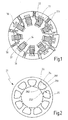
- Fig. 1
- eine perspektivische Stirnansicht eines Stators für eine Innenläufermaschine,
- Fig. 2
- eine Stirnansicht eines Statorkörpers des Stators in
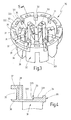
Fig. 1 , - Fig. 3
- eine perspektivische Ansicht eines Oberteils einer auf den Statorkörper aufgesetzten Maske gemäß
Fig. 1 , - Fig. 4
- ausschnittweise einen Längsschnitt gemäß Linie IV - IV in
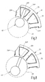
Fig. 3 , - Fig. 5 bis 9
- jeweils ausschnittweise eine schematisierte Draufsicht eines Statorkörpers und einer Drahtführungsvorrichtung in fünf verschiedenen Zuständen beim Einwickeln einer Spule der Statorwicklung in
Fig. 1 , - Fig. 10
und 11 - jeweils ausschnittweise eine gleiche Schnittdarstellung wie in
Fig. 4 mit aufgewickelter Spule der Statorwicklung, - Fig. 12
- eine Stirnansicht eines Statorkörpers gemäß einem weiteren Ausführungsbeispiel,.
- Fig. 13
- eine Illustrierung eines bekannten Wickelverfahrens nach dem Stand der Technik in vier verschiedenen Wickelschritten a bis d.
- Fig. 1
- a perspective end view of a stator for an internal rotor machine,
- Fig. 2
- an end view of a stator of the stator in
Fig. 1 . - Fig. 3
- a perspective view of an upper part of a patch on the stator body mask according to
Fig. 1 . - Fig. 4
- partially a longitudinal section along line IV - IV in
Fig. 3 . - Fig. 5 to 9
- in each case a schematic top view of a stator body and a wire guide device in five different states when wrapping a coil of the stator winding in
Fig. 1 . - 10 and 11
- each section a same sectional view as in
Fig. 4 with wound coil of the stator winding, - Fig. 12
- an end view of a stator body according to another embodiment,.
- Fig. 13
- an illustration of a known winding method according to the prior art in four different winding steps a to d.
Das Hauptelement für eine elektrische Maschine wird nachfolgend am Beispiel eines Stators einer Innenläufermaschine, z.B. eines Gleichstrommotors, beschrieben. Das Hauptelement kann aber in gleicher Ausführung auch ein Rotor einer Außenläufermaschine sein, so dass die nachfolgend verwendeten Begriffe Statorkörper für den magnetisch leitfähigen Körper und Statorwicklung für die elektrische Wicklung auch synonym für Rotorkörper und Rotorwicklung einer Außenläufermaschine stehen.The main element for an electric machine will be described below using the example of a stator of an internal rotor machine, e.g. a DC motor, described. However, the main element can also be a rotor of an external rotor machine in the same design, so that the terms stator stator used for the magnetically conductive body and stator winding for the electrical winding are also synonymous with the rotor body and rotor winding of an external rotor machine.
Der Stator weist einen als Statorkörper 21 bezeichneten Körper aus magnetisch leitfähigem Material, der in bekannter Weise aus einer Vielzahl von zu einem Stanzpaket zusammengesetzten Einzellamellen besteht, sowie eine Statorwicklung 22 bezeichnete elektrische Wicklung auf. Der Statorkörpers 21 besteht aus einem Rückschlussring 24 und einer Mehrzahl von Zähnen 25 mit Zahnschaft 251 und Zahnschuh 252. Die Zähne 25 sind um gleiche Umfangswinkel zueinander versetzt am Rückschlussring 24, von diesem radial nach innen abstehend angeordnet und tragen am freien Ende ihrer Zahnschäfte 251 die Zahnschuhe 252. Die Zähne 25 schließen zwischen sich axial verlaufende Nuten 26 ein, die sich zu dem vom Rückschlussring 24 gebildeten Nutgrund 261 verbreitern und deren vom Nutgrund 261 abgekehrte Nutöffnung von den Zahnschuhen 252 der beiden jeweils eine Nut 26 einschließenden Zähne 25 bis auf einen Nutspalt 262 verschlossen ist.The stator has a body, referred to as a
Die Statorwicklung 22 besteht aus miteinander verschalteten Spulen 221, die mit einem Wickeldraht 27 gegenüber dem Statorkörper 21 elektrisch isoliert in mehreren Wickellagen auf die Zähne 25 des Statorkörpers 21 so aufgewickelt sind, dass ihre axial sich erstreckenden Spulenseiten in den Nuten 26 einliegen und ihre bogenförmigen Spulenköpfe die Stirnseiten der Zahnschäfte 251 überdecken.The stator winding 22 consists of
Zur elektrischen Isolation zwischen Statorkörper 21 und Statorwicklung 22 ist eine Maske 30 aus elektrisch isolierendem Material, z.B. Kunststoff, vorgesehen, die axial zweigeteilt, vorzugsweise hälftig geteilt, ist und deren oberer Teil in
Die als Kunststoffspritzteil hergestellte Maske 30 weist eine Zahnverkleidung 31 zum Abdecken der Seiten- und Stirnflächen der Zahnschäfte 251 und eine Nutgrundabdeckung oder Nutgrundbekleidung 32 zum Abdecken der die Nutgründe bildenden Abschnitte des Rückschlussrings 24 auf. Die Nutgrundbekleidung 32 ist einstückig mit der Zahnverkleidung 31 und verbindet die einzelnen Ausprägungen der Zahnverkleidung 31 an den einzelnen Zähne 25. Wie aus der perspektivischen Ansicht in
Der untere Maskenteil der Maske 30 ist in identischer Weise ausgebildet wie der bis hier beschriebene obere Maskenteil der Maske 30. Gegenüber dem unteren Maskenteil weist der obere Maskenteil noch zusätzlich eine an seiner Stirnseite angeformte Verlegehilfe für den Wickeldraht 27 auf, um die Verschaltung der Spulen 221, also das Führen des Wickeldrahts 27 von einer Spule 221 zur nächsten Spule 221 der Statorwicklung 22 zu erleichtern. Hierzu ist an der vom unteren Maskenteil der Maske 30 abgekehrten Stirnseite des oberen Maskenteils der Maske 30 ein im Querschnitt U-förmiger Verlegekanal 35 mit zwei Kanalwänden und einem die Kanalwände miteinander verbindenden Kanalboden vorgesehen, der mit einer radial nach außen weisenden Öffnung über nahezu den gesamten Umfang der Maske 30 umläuft. Die eine Kanalwand bildet eine Abdeckung 36 für die Stirnfläche des hohlzylindrischen Rückschlussrings 22, und die andere Kanalwand und der Kanalboden werden von im Längsschnitt etwa L-förmigen Segmenten 37 gebildet, die voneinander beabstandet derart angeordnet sind, dass ihre radialen Symmetrie- oder Mittellinien mit den Mittellinien der einzelnen Ausprägungen der Zahnverkleidung 31 an den Zähnen 25 fluchten. In dem in
In jedem der Segmente 37 ist ein axialer Aufnahmeschacht 38 zum Einstecken von hier nicht dargestellten Kontaktfahnen ausgebildet. Ein Aufnahmeschacht 38 ist im Schnitt in
Das Aufwickeln der Statorwicklung 22 auf den Statorkörper 21 wird nachstehend anhand der
Auf den Statorkörper 21 werden die beiden Maskenteile der Maske 30 von beiden Stirnseiten her axial aufgeschoben, bis sich die Schnittstellen 301 der beiden Maskenteile mit Spaltabstand gegenüberliegen. Alternativ kann der Statorkörper 21 auch mit der Maske 30 in der beschriebenen Ausgestaltung umspritzt werden, wobei in diesem Fall auf den Spalt zwischen den Maskenteilen verzichtet wird. Der mit der Maske 30 versehene Statorkörper 21 wird in einen Wickelautomaten eingesetzt und kann beim Wickeln um definierte Schaltschritte, die jeweils einer Zahnteilung des Statorkörpers 21 entsprechen, in Umfangsrichtung in beide Richtungen gedreht werden. Im hohlen Innern des Statorkörpers 21 ist eine Drahtführungsvorrichtung 40 so angeordnet, dass sie einen axialen und radialen Hub auszuführen vermag, jeweils bezogen auf den Statorkörper 21. Die Drahtführungsvorrichtung 40 umfasst eine Nadel 41, die in Axialrichtung verschiebbar ist, und eine von der Nadel 41 radial abstehende Düse 42 mit einem Drahtausziehende 401. Die Nadel 41 führt einen Axialhub aus zwischen einer unteren Endposition, in welcher die Düse 42 unterhalb der Stirnseite des Statorkörpers 21 liegt, und einer oberen Endposition, in welcher die Düse 42 oberhalb der oberen Stirnseite des Statorkörpers 21 liegt. In ihren Endpositionen vermag die Nadel 41 eine radiale Hubbewegung auszuführen, durch die sich das Drahtausziehende 401 der Düse 42 über die Stirnflächen der axial offenen Nuten 26 hinwegschiebt und wieder hinter den Zahnschuhkreis 28 zurückzieht.On the
In
In
In
Ist die Spule 221 komplett auf den Zahn 25 aufgewickelt, so wird der Statorkörper 21 bis zum nächsten Zahn 25, der die zum Wicklungsstrang gehörige nächste Spule 221 aufzunehmen hat, geschwenkt, wobei der Wickeldraht 27 in den Verlegekanal 35 eingelegt wird. Die Drahtführungsvorrichtung 40 legt nunmehr durch axiales Verschieben des Drahtausziehendes 401 nach unten die erste Windung in die neue Nut 26 ein. Danach nimmt die Drahtführungsvorrichtung 40 wieder die in
Das Einlegen der einzelnen Windungen 1 bis 9 der Spule 221 kann auch in der in
Beim Wickeln der Spulen 221 wird der Wickeldraht 27 in Kontaktfahnen eingehängt, die in durch die Stranglage der Wicklungsstränge bedingten, ausgewählten Aufnahmeschächte 38 der Maske 30 vor der Bewicklung eingesetzt worden sind.When winding the
Das Wickelverfahren eignet sich auch für einen magnetisch leitfähigen Körper 21', dessen Stirnansicht in
Claims (12)
- Method for winding an electrical winding (22), which is composed of a winding wire (27), onto a magnetically permeable body (21) of a main element of an electrical machine, which body has a magnetic return ring (24) and teeth (25) which project, in particular in an integral manner, from the said magnetic return ring, which are formed between slots (26) that run in the axial direction and are open at the ends, and which have tooth shafts (251) and tooth shoes (252) which cover the slot openings apart from a slot gap (262), in which method the winding wire (27) is continuously inserted into the slots (26) by means of a wire-guiding apparatus (40) with a wire pull-out end (401), which executes at least one axial reciprocating movement, and by means of a relative rotation of the wire pull-out end (401) and the body (21) in the circumferential direction of the body, the said rotation being performed in each case with the wire pull-out end (401) situated over the end areas of the slots (26), and is wound on, in a manner guided over the end faces of the tooth shafts (251), so as to form ring coils (221) which are tightened on the tooth shaft by pulling the wire, wherein, before the body is wound, a mask (30), which is composed of electrically insulating material, preferably of plastic, and covers the body (21) with a tooth covering (31) in the tooth region and with a slot base lining (32) in the slot region, is fitted onto the body (21) and, when the winding wire (27) is wound in, is used as a winding aid for positioning the winding wire (27) into the slots (26), characterized in that, in order to form the winding aid, the tooth covering (31) is provided, in its regions (311) which cover the end faces of the tooth shafts (251), in each case with a radially running step arrangement (33), which has at least one step (331) with an axially oriented step edge (333) which faces the slot base lining (32), and with an axially projecting retaining flange (34) which bounds the step (331) at its end which is averted from the slot base lining (32), and in that the winding wire (27) is pulled, in a lower winding layer, over the step arrangement section (332) of the step arrangement (33) which is situated between the step edge (333) and the slot base lining (32) and is axially recessed in relation to the step (331), and, in at least a second winding layer, is pulled over the lower winding layer and the at least one step (331), and, to this end, the wire-guiding apparatus (40) is controlled such that the wire pull-out end (401) of the said wire-guiding apparatus is always guided outside the slots (26) in front of the tooth shoe circuit (28) during the axial reciprocating movement, and a radial reciprocating movement is executed over the end areas of the slots (26), and in that the relative rotation of the wire pull-out end (401) and the stator body (21) is carried out by rotating the body (21).
- Method according to Claim 1, characterized in that the mask (30) is provided, at one end, with a laying channel (35) which is U-shaped in cross section and has two channel walls and a channel base, one channel wall of the said laying channel forming a cover (36) for the end area of the magnetic return ring (24) and the other channel wall of the said laying channel and the channel base of the said laying channel being formed from segments (37) which are spaced apart from one another and of which the radial lines of symmetry are in alignment with the radial centre lines of the teeth (25), and in that, during winding, the winding wire (27) is guided from one ring coil (221) to the next through the gaps which are present between the segments (37) and through the laying channel (35).
- Method according to Claim 2, characterized in that an axial receiving shaft (38) for a contact lug is formed in at least one segment (37), preferably in each segment (37), and in that contact lugs are inserted into selected receiving shafts (38) and occupied by the winding wire (27).
- Method according to one of Claims 1 to 3, characterized in that the mask (30) is divided axially, preferably in half, and in that in each case one mask part is pushed onto the body (21) from in each case one end face of the body (21).
- Mask for establishing electrical insulation between a magnetically permeable body (21) with a magnetic return ring (24) and integrally formed, radially projecting teeth (25) which each have a tooth shaft (251) and a tooth shoe (252) and which between them form slots (26), which run in the axial direction and are open at the ends, and an electrical winding (22), which is wound onto the tooth shafts (251) in ring coils (221), of a main element of an electrical machine, which mask has a tooth covering (31) for covering the longitudinal and end faces of the tooth shafts (251) and a slot base lining (32) for covering the sections of the magnetic return ring (24) which form the slot bases, and a winding aid for winding in a winding wire (27) which forms the coils (221), characterized in that the winding aid has a radially extending step arrangement (33) which is arranged in each of the regions (311) of the tooth covering (31) which cover the end faces of the tooth shafts (251) and has at least one step (331) with an axially extending step edge (333) which faces the slot base lining (32), which step is delimited by an axially projecting retaining flange (34) at its free end which is averted from the slot base lining (32).
- Mask according to Claim 8, characterized in that the axial height of the at least one step (331) is slightly greater than the outside diameter of the winding wire (27), and the radial length of the step (331) and a step arrangement section (332), which radially adjoins the said step and is axially recessed in relation to the step (331), in each case amounts to an integer multiple of the outside diameter of the winding wire (27).
- Mask according to Claim 5 or 6, characterized in that at least one laying channel (35) which is of U-shaped design in cross section and has two channel walls and a channel base is integrally formed on one of the ends of the mask (30), one channel wall of the said laying channel forming a cover (36) for the end area of the magnetic return ring (24) and the other channel wall of the said laying channel and the channel base of the said laying channel being formed from segments (37) which are spaced apart from one another and of which the radial lines of symmetry are each in alignment with the radial centre line of a shaped portion of the tooth covering (31) which surrounds a tooth shaft (251).
- Mask according to Claim 7, characterized in that an axial receiving shaft (38) for the insertion of a contact lug for the electrical connection of the winding (22) is arranged in at least one segment (37).
- Mask according to one of Claims 5 to 8, characterized in that the tooth covering (31) and the slot base lining (32) are integrally formed and are divided axially, preferably in half.
- Mask according to Claim 9, characterized in that the laying channel (35) with receiving shafts (38) is integrally formed on one mask part.
- Mask according to one of Claims 5 to 10, characterized in that an axially recessed step arrangement section (332) for receiving a lower winding layer of the ring coils (221) which are formed by the winding wire (27) is present between the slot base lining (32) and the step edge (333) of the step arrangement (33), and the at least one step (331) of the step arrangement (33) serves, together with the lower winding layer of the ring coils (221) which is situated in the step arrangement section (332), to receive a further winding layer of the ring coils (221).
- Main element, characterized in that the mask (30) which is composed of insulating material is sprayed directly onto the body (21).
Applications Claiming Priority (1)
| Application Number | Priority Date | Filing Date | Title |
|---|---|---|---|
| DE200410042737 DE102004042737A1 (en) | 2004-09-03 | 2004-09-03 | Method for winding an electrical winding for an electrical machine |
Publications (3)
| Publication Number | Publication Date |
|---|---|
| EP1633035A2 EP1633035A2 (en) | 2006-03-08 |
| EP1633035A3 EP1633035A3 (en) | 2010-09-29 |
| EP1633035B1 true EP1633035B1 (en) | 2014-05-21 |
Family
ID=35115796
Family Applications (1)
| Application Number | Title | Priority Date | Filing Date |
|---|---|---|---|
| EP20050107450 Not-in-force EP1633035B1 (en) | 2004-09-03 | 2005-08-12 | Method of winding an electric coil for an electrical machine |
Country Status (2)
| Country | Link |
|---|---|
| EP (1) | EP1633035B1 (en) |
| DE (1) | DE102004042737A1 (en) |
Families Citing this family (5)
| Publication number | Priority date | Publication date | Assignee | Title |
|---|---|---|---|---|
| DE102011089238A1 (en) * | 2011-12-20 | 2013-06-20 | Continental Automotive Gmbh | Method and device for producing wound and interconnected pole teeth of stators |
| AT513114B1 (en) * | 2012-06-27 | 2016-01-15 | Egston System Electronics Eggenburg Gmbh | coil winding |
| DE102017215681A1 (en) * | 2017-09-06 | 2019-03-07 | Robert Bosch Gmbh | Method for winding an electrical winding |
| FR3127657A1 (en) * | 2021-09-30 | 2023-03-31 | Valeo Systèmes D’Essuyage | Coil for an electric motor stator, associated stator and associated manufacturing method |
| CN114905261B (en) * | 2022-06-08 | 2024-01-23 | 深圳市兴特创自动化设备有限公司 | Full-automatic rotor magnetic ring clamp spring assembling machine and using method thereof |
Family Cites Families (4)
| Publication number | Priority date | Publication date | Assignee | Title |
|---|---|---|---|---|
| EP0064105B1 (en) * | 1981-05-06 | 1985-10-23 | AMP INCORPORATED (a New Jersey corporation) | Electric motor stator and a method of manufacturing the stator |
| JP3680482B2 (en) * | 1997-03-28 | 2005-08-10 | 松下電器産業株式会社 | Electric motor stator constituent member, electric motor stator, electric motor manufacturing method |
| JPH10304605A (en) * | 1997-04-24 | 1998-11-13 | Toshiba Corp | Direct-current motor |
| US6590310B2 (en) * | 2001-02-21 | 2003-07-08 | Kabushiki Kaisha Moric | Stator coil structure for revolving-field electrical machine and method of manufacturing same |
-
2004
- 2004-09-03 DE DE200410042737 patent/DE102004042737A1/en not_active Withdrawn
-
2005
- 2005-08-12 EP EP20050107450 patent/EP1633035B1/en not_active Not-in-force
Also Published As
| Publication number | Publication date |
|---|---|
| EP1633035A3 (en) | 2010-09-29 |
| DE102004042737A1 (en) | 2006-03-09 |
| EP1633035A2 (en) | 2006-03-08 |
Similar Documents
| Publication | Publication Date | Title |
|---|---|---|
| EP3523872B1 (en) | Coil winding for stators and rotors | |
| EP3542446B1 (en) | Wave winding coil for a stator laminated core of an electrical machine | |
| DE102009032882B3 (en) | Method for producing preformed coil for floor winding of dynamo-electric machine using raw coil, involves bending longitudinal sides around specific degrees such that end winding sides are bent at angle from longitudinal sides | |
| DE3212196C2 (en) | ||
| DE102011054373A1 (en) | Stator, brushless motor and manufacturing method thereof | |
| EP0968563B1 (en) | Method and device for producing wave windings for electrical machines | |
| DE19818433A1 (en) | DC motor and method of manufacturing the same | |
| DE60309539T2 (en) | Plurality of conductor sections Stator windings for electric lathes, and method for its manufacture | |
| DE102009024230A1 (en) | Method for producing a stator winding of an electrical machine, in particular for producing an alternating current generator | |
| DE112013004152T5 (en) | Coil stator assembly for a rotating electrical machine | |
| EP1633035B1 (en) | Method of winding an electric coil for an electrical machine | |
| DE102015225586A1 (en) | Bobbin for an electric coil | |
| EP1494338B1 (en) | Manufacturing method for a core of an electic machine | |
| DE102010053719A1 (en) | Method for manufacturing stator winding of alternating current generator for motor car, involves providing grooves with material-deforming tool, where grooves are suitable to receive coils, and arranging coils in grooves | |
| DE60018374T2 (en) | Method and apparatus with loop-forming wire strippers for winding stators of dynamoelectric machines | |
| EP2668712B1 (en) | Electric machine and method for winding a coil of an electric machine | |
| WO2015082270A2 (en) | Winding segment for forming a winding of an electrical machine, method for producing a winding segment | |
| EP2994980B1 (en) | Continuous stator winding wound on a coil carrier | |
| DE10329576A1 (en) | Method for producing a two-layer loop winding | |
| DE19817304B4 (en) | Method and device for producing shaft windings for electrical machines | |
| DE102010043976A1 (en) | Component for manufacturing machine component e.g. stator for electric machine, has several teeth which are arranged at base portion in arrangement direction, and base portion comprises one or more upsetting regions between each teeth | |
| DE19917057A1 (en) | Armature for dynamo-electric machine, especially motor, has commutator with several segments connected selectively by equalization arrangement connectors, so that segments have equal voltages | |
| EP3167540B1 (en) | Method for producing an electrical machine using pre-formed coils and electrical machine and production tool | |
| WO2015000639A2 (en) | Machine component for an electric machine with multiple coils | |
| DE102009001543A1 (en) | Electric machine and method for manufacturing an electric machine |
Legal Events
| Date | Code | Title | Description |
|---|---|---|---|
| PUAI | Public reference made under article 153(3) epc to a published international application that has entered the european phase |
Free format text: ORIGINAL CODE: 0009012 |
|
| AK | Designated contracting states |
Kind code of ref document: A2 Designated state(s): AT BE BG CH CY CZ DE DK EE ES FI FR GB GR HU IE IS IT LI LT LU LV MC NL PL PT RO SE SI SK TR |
|
| AX | Request for extension of the european patent |
Extension state: AL BA HR MK YU |
|
| PUAL | Search report despatched |
Free format text: ORIGINAL CODE: 0009013 |
|
| AK | Designated contracting states |
Kind code of ref document: A3 Designated state(s): AT BE BG CH CY CZ DE DK EE ES FI FR GB GR HU IE IS IT LI LT LU LV MC NL PL PT RO SE SI SK TR |
|
| AX | Request for extension of the european patent |
Extension state: AL BA HR MK YU |
|
| RIC1 | Information provided on ipc code assigned before grant |
Ipc: H02K 15/095 20060101ALI20100825BHEP Ipc: H02K 3/52 20060101ALI20100825BHEP Ipc: H02K 15/085 20060101AFI20051028BHEP |
|
| 17P | Request for examination filed |
Effective date: 20110329 |
|
| AKX | Designation fees paid |
Designated state(s): CH DE FR IT LI |
|
| 17Q | First examination report despatched |
Effective date: 20110729 |
|
| REG | Reference to a national code |
Ref country code: DE Ref legal event code: R079 Ref document number: 502005014364 Country of ref document: DE Free format text: PREVIOUS MAIN CLASS: H02K0015085000 Ipc: H02K0003180000 |
|
| RIC1 | Information provided on ipc code assigned before grant |
Ipc: H02K 3/18 20060101AFI20120427BHEP Ipc: H02K 3/52 20060101ALI20120427BHEP Ipc: H02K 15/095 20060101ALI20120427BHEP |
|
| GRAP | Despatch of communication of intention to grant a patent |
Free format text: ORIGINAL CODE: EPIDOSNIGR1 |
|
| INTG | Intention to grant announced |
Effective date: 20140218 |
|
| GRAS | Grant fee paid |
Free format text: ORIGINAL CODE: EPIDOSNIGR3 |
|
| GRAA | (expected) grant |
Free format text: ORIGINAL CODE: 0009210 |
|
| AK | Designated contracting states |
Kind code of ref document: B1 Designated state(s): CH DE FR IT LI |
|
| REG | Reference to a national code |
Ref country code: CH Ref legal event code: EP |
|
| REG | Reference to a national code |
Ref country code: DE Ref legal event code: R096 Ref document number: 502005014364 Country of ref document: DE Effective date: 20140710 |
|
| REG | Reference to a national code |
Ref country code: DE Ref legal event code: R097 Ref document number: 502005014364 Country of ref document: DE |
|
| REG | Reference to a national code |
Ref country code: DE Ref legal event code: R119 Ref document number: 502005014364 Country of ref document: DE |
|
| PLBE | No opposition filed within time limit |
Free format text: ORIGINAL CODE: 0009261 |
|
| STAA | Information on the status of an ep patent application or granted ep patent |
Free format text: STATUS: NO OPPOSITION FILED WITHIN TIME LIMIT |
|
| REG | Reference to a national code |
Ref country code: CH Ref legal event code: PL |
|
| 26N | No opposition filed |
Effective date: 20150224 |
|
| PG25 | Lapsed in a contracting state [announced via postgrant information from national office to epo] |
Ref country code: LI Free format text: LAPSE BECAUSE OF NON-PAYMENT OF DUE FEES Effective date: 20140831 Ref country code: CH Free format text: LAPSE BECAUSE OF NON-PAYMENT OF DUE FEES Effective date: 20140831 Ref country code: IT Free format text: LAPSE BECAUSE OF FAILURE TO SUBMIT A TRANSLATION OF THE DESCRIPTION OR TO PAY THE FEE WITHIN THE PRESCRIBED TIME-LIMIT Effective date: 20140521 |
|
| REG | Reference to a national code |
Ref country code: DE Ref legal event code: R119 Ref document number: 502005014364 Country of ref document: DE Effective date: 20150303 |
|
| REG | Reference to a national code |
Ref country code: FR Ref legal event code: ST Effective date: 20150430 |
|
| REG | Reference to a national code |
Ref country code: DE Ref legal event code: R097 Ref document number: 502005014364 Country of ref document: DE Effective date: 20150224 |
|
| PG25 | Lapsed in a contracting state [announced via postgrant information from national office to epo] |
Ref country code: DE Free format text: LAPSE BECAUSE OF NON-PAYMENT OF DUE FEES Effective date: 20150303 |
|
| PG25 | Lapsed in a contracting state [announced via postgrant information from national office to epo] |
Ref country code: FR Free format text: LAPSE BECAUSE OF NON-PAYMENT OF DUE FEES Effective date: 20140901 |