EP1632881B1 - Verbindungsanordnung für Chipkarten mit Sicherungsmitteln vor Betrug - Google Patents
Verbindungsanordnung für Chipkarten mit Sicherungsmitteln vor Betrug Download PDFInfo
- Publication number
- EP1632881B1 EP1632881B1 EP05108024A EP05108024A EP1632881B1 EP 1632881 B1 EP1632881 B1 EP 1632881B1 EP 05108024 A EP05108024 A EP 05108024A EP 05108024 A EP05108024 A EP 05108024A EP 1632881 B1 EP1632881 B1 EP 1632881B1
- Authority
- EP
- European Patent Office
- Prior art keywords
- blade
- connection assembly
- assembly according
- protective
- connector
- Prior art date
- Legal status (The legal status is an assumption and is not a legal conclusion. Google has not performed a legal analysis and makes no representation as to the accuracy of the status listed.)
- Ceased
Links
Images



Classifications
-
- G—PHYSICS
- G06—COMPUTING OR CALCULATING; COUNTING
- G06K—GRAPHICAL DATA READING; PRESENTATION OF DATA; RECORD CARRIERS; HANDLING RECORD CARRIERS
- G06K7/00—Methods or arrangements for sensing record carriers, e.g. for reading patterns
- G06K7/0013—Methods or arrangements for sensing record carriers, e.g. for reading patterns by galvanic contacts, e.g. card connectors for ISO-7816 compliant smart cards or memory cards, e.g. SD card readers
-
- G—PHYSICS
- G06—COMPUTING OR CALCULATING; COUNTING
- G06K—GRAPHICAL DATA READING; PRESENTATION OF DATA; RECORD CARRIERS; HANDLING RECORD CARRIERS
- G06K7/00—Methods or arrangements for sensing record carriers, e.g. for reading patterns
- G06K7/0013—Methods or arrangements for sensing record carriers, e.g. for reading patterns by galvanic contacts, e.g. card connectors for ISO-7816 compliant smart cards or memory cards, e.g. SD card readers
- G06K7/0086—Methods or arrangements for sensing record carriers, e.g. for reading patterns by galvanic contacts, e.g. card connectors for ISO-7816 compliant smart cards or memory cards, e.g. SD card readers the connector comprising a circuit for steering the operations of the card connector
- G06K7/0091—Methods or arrangements for sensing record carriers, e.g. for reading patterns by galvanic contacts, e.g. card connectors for ISO-7816 compliant smart cards or memory cards, e.g. SD card readers the connector comprising a circuit for steering the operations of the card connector the circuit comprising an arrangement for avoiding intrusions and unwanted access to data inside of the connector
-
- H—ELECTRICITY
- H01—ELECTRIC ELEMENTS
- H01R—ELECTRICALLY-CONDUCTIVE CONNECTIONS; STRUCTURAL ASSOCIATIONS OF A PLURALITY OF MUTUALLY-INSULATED ELECTRICAL CONNECTING ELEMENTS; COUPLING DEVICES; CURRENT COLLECTORS
- H01R12/00—Structural associations of a plurality of mutually-insulated electrical connecting elements, specially adapted for printed circuits, e.g. printed circuit boards [PCB], flat or ribbon cables, or like generally planar structures, e.g. terminal strips, terminal blocks; Coupling devices specially adapted for printed circuits, flat or ribbon cables, or like generally planar structures; Terminals specially adapted for contact with, or insertion into, printed circuits, flat or ribbon cables, or like generally planar structures
- H01R12/70—Coupling devices
- H01R12/71—Coupling devices for rigid printing circuits or like structures
- H01R12/712—Coupling devices for rigid printing circuits or like structures co-operating with the surface of the printed circuit or with a coupling device exclusively provided on the surface of the printed circuit
- H01R12/714—Coupling devices for rigid printing circuits or like structures co-operating with the surface of the printed circuit or with a coupling device exclusively provided on the surface of the printed circuit with contacts abutting directly the printed circuit; Button contacts therefore provided on the printed circuit
-
- H—ELECTRICITY
- H01—ELECTRIC ELEMENTS
- H01R—ELECTRICALLY-CONDUCTIVE CONNECTIONS; STRUCTURAL ASSOCIATIONS OF A PLURALITY OF MUTUALLY-INSULATED ELECTRICAL CONNECTING ELEMENTS; COUPLING DEVICES; CURRENT COLLECTORS
- H01R13/00—Details of coupling devices of the kinds covered by groups H01R12/70 or H01R24/00 - H01R33/00
- H01R13/44—Means for preventing access to live contacts
- H01R13/447—Shutter or cover plate
- H01R13/453—Shutter or cover plate opened by engagement of counterpart
- H01R13/4536—Inwardly pivoting shutter
-
- H—ELECTRICITY
- H01—ELECTRIC ELEMENTS
- H01R—ELECTRICALLY-CONDUCTIVE CONNECTIONS; STRUCTURAL ASSOCIATIONS OF A PLURALITY OF MUTUALLY-INSULATED ELECTRICAL CONNECTING ELEMENTS; COUPLING DEVICES; CURRENT COLLECTORS
- H01R13/00—Details of coupling devices of the kinds covered by groups H01R12/70 or H01R24/00 - H01R33/00
- H01R13/02—Contact members
- H01R13/22—Contacts for co-operating by abutting
- H01R13/24—Contacts for co-operating by abutting resilient; resiliently-mounted
Definitions
- the present invention relates to a connection assembly for connecting an electronic memory card that includes a plurality of electrical contact pads on one of its main faces.
- the blades are arranged parallel to a longitudinal horizontal direction that corresponds to the direction of insertion of the card when the latter is inserted horizontally parallel to its plane.
- each contact blade comprises:
- the connector includes at least one called "signal" contact blade.
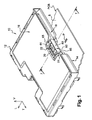
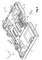
- the general design of the connector 10 with its insulating body 12 is here of the type described and shown in the documents WO-A-98/52139 and US-B1-6 345 881 .
- the case 12 essentially consists of a lower horizontal plate 14 and an upper horizontal plate 16 which between them define a longitudinal slot 18 for the forward insertion, from the rear, along the direction indicated by the arrow "L" in Figures 1 and 2 , of a memory card (not shown) that includes, on its lower face oriented so as to be opposite the upper facing face 20 of the lower plate 14, conducting pads placed in a standardized fashion.
Landscapes
- Engineering & Computer Science (AREA)
- Artificial Intelligence (AREA)
- Computer Vision & Pattern Recognition (AREA)
- Physics & Mathematics (AREA)
- General Physics & Mathematics (AREA)
- Theoretical Computer Science (AREA)
- Coupling Device And Connection With Printed Circuit (AREA)
- Details Of Connecting Devices For Male And Female Coupling (AREA)
- Fittings On The Vehicle Exterior For Carrying Loads, And Devices For Holding Or Mounting Articles (AREA)
- Connector Housings Or Holding Contact Members (AREA)
- Credit Cards Or The Like (AREA)
Claims (15)
- Verbindungsanordnung (8 - 10) zum Anschluss einer elektronischen Speicherkarte, die auf einer ihrer Hauptflächen eine Mehrzahl elektrischer Kontaktflächen des Typs umfasst, der auf seiner Oberseite (8) eine Auflagerung für eine gedruckte Schaltung, einen elektrischen Verbinder (10) mit einem Kontaktblock (14) aus Isolationsmaterial mit einer ebenen horizontalen Oberseite (20) und einer Mehrzahl elektrischer Leiter (22, 22a) in Form von elastisch verformbaren Messern aufweist, die parallel zu einer horizontalen Längsrichtung angeordnet sind, wobei jedes Kontaktmesser (22, 22a) die folgenden Merkmale umfasst:- ein kurvenförmiges erstes Ende zum Kontaktieren einer entsprechenden Fläche auf der Karte, wobei dieses erste Ende in der Lage ist, aus der ebenen Oberseite (20) des Isolierblocks (14) hervorzuragen;- einen mittleren Längsabschnitt (30, 30a) zum Verbinden des Messers mit dem Isolierblock (14); und- ein zweites Ende zum Verbinden des Messers, das eine Kontaktfläche (34, 34a) zum elektrischen Anschluss des Messers (22, 22a) an eine Leiterbahn auf der Oberseite (8) der gedruckten Schaltung darstellt,gekennzeichnet dadurch, dass
wobei der Verbinder wenigstens ein "Signal"-Kontaktmesser (22a) umfasst;
der Verbinder wenigstens eine Metall-Schutzplatte (42, 44, 50) umfasst, die sich gegenüber einem Abschnitt des Signal-Kontaktmessers (22a) erstreckt, welcher der Metall-Schutzplatte zugewandt ist, und mit einem "Erd"-Leiter (P) auf der Oberseite (8) der gedruckten Schaltung elektrisch verbunden ist, der Teil eines Erdungskreises ist. - Verbindungsanordnung nach dem vorstehenden Anspruch, dadurch gekennzeichnet, dass der Verbinder wenigstens eine erste Metall-Schutzplatte (42) umfasst, welche sich vertikal gegenüber einem Abschnitt (36a) der Kontaktfläche (34a) zum Verbinden des Signal-Kontaktmessers (22a) erstreckt und elektrisch mit dem Erdleiter (P) verbunden ist.
- Verbindungsanordnung nach einem der vorstehenden Ansprüche, dadurch gekennzeichnet, dass die erste Metall-Schutzplatte (42) in einer Querebene im rechten Winkel zur Längsrichtung (L) der Anschlussfläche (34a) angeordnet ist, die sie schützt.
- Verbindungsanordnung nach dem vorstehenden Anspruch, dadurch gekennzeichnet, dass die Anschlussfläche (34a) des ersten Signal-Kontaktmessers (22a) wenigstens einen vertikalen Abzweig (36a) in Querausrichtung parallel zur ersten Schutzplatte (42) umfasst.
- Verbindungsanordnung nach dem vorstehenden Anspruch, dadurch gekennzeichnet, dass die Anschlussfläche (34a) des ersten Signal-Kontaktmessers (22a) wenigstens einen unteren horizontalen Abzweig (38a) umfasst, der den vertikalen Abzweig (36a) nach hinten verlängert und im Wesentlichen in der Ebene der Unterseite (21) des Isolierblocks (14) angeordnet ist.
- Verbindungsanordnung nach dem vorstehenden Anspruch,dadurch gekennzeichnet, dass die erste Schutzplatte (42) ein unteres Verlängerungs-Schutzstück (54) aufweist, das sich gegenüber der Anschlussfläche (34a) erstreckt.
- Verbindungsanordnung nach dem vorstehenden Anspruch,dadurch gekennzeichnet, dass das Verlängerungsstück einen leitenden Zungenabschnitt (54) darstellt, der sich längs nach hinten erstreckt, wobei das freie Ende (56) des Zungenabschnitts sich in elektrischem Kontakt mit dem Erdleiter (P) befindet.
- Verbindungsanordnung nach einem der vorstehenden Ansprüche, dadurch gekennzeichnet, dass der Verbinder (10) zwei zweite gegenseitig parallele und gegenüberliegende Schutzplatten (44) umfasst, die sich jeweils vertikal gegenüber einem Abschnitt der Anschlussfläche (34a) des Signal-Kontaktmessers (22a) erstrecken, in einer seitlichen Ebene parallel zur Längsrichtung (L) der Kontaktfläche (34a), die sie schützen, befinden und elektrisch mit dem Erdleiter (P) verbunden sind, um die Anschlussfläche auf beiden Längsflächen zu schützen.
- Verbindungsanordnung nach einem der vorstehenden Ansprüche, dadurch gekennzeichnet, dass der Verbinder wenigstens eine Metall-Schutzplatte (50) umfasst, die sich horizontal über und gegenüber einem Abschnitt des Signal-Kontaktmessers (22a) erstreckt.
- Verbindungsanordnung nach dem vorstehenden Anspruch in Kombination mit einem der Ansprüche 5 bis 7, dadurch gekennzeichnet, dass die horizontale Schutzplatte (50) sich gegenüber dem unteren horizontalen Abzweig (38a) der Anschlussfläche (34a) des Signal-Kontaktmessers erstreckt.
- Verbindungsanordnung nach einem der vorstehenden Ansprüche, dadurch gekennzeichnet, dass jede Schutzplatte (42, 44, 50) zu einem Metall-Schutzkäfig (40) gehört.
- Verbindungsanordnung nach einem der vorstehenden Ansprüche, dadurch gekennzeichnet, dass der Verbinder eine Halterung (60) aus Isolationsmaterial umfasst, welche die einzelnen Schutzplatten trägt und in einem Komplementärgehäuse (64) des Isolierblocks (14) angebracht ist.
- Verbindungsanordnung nach dem vorstehenden Anspruch, dadurch gekennzeichnet, dass die Isolierhalterung (60) so angebracht ist, dass sie sich relativ zum Isolierblock (14) und zur Oberseite (8) der gedruckten Schaltung zwischen einer anfänglichen, temporären und gerasteten Gebrauchsstellung, in der das Signal-Kontaktmesser (22a) nicht geschützt ist, und einer Endstellung zum Schutz des Signal-Kontaktmessers (22a) bewegt, in der sich jede Schutzplatte in Schutzstellung befindet und mit dem Erdleiter (P) verbunden ist.
- Verbindungsanordnung nach dem vorstehenden Anspruch, dadurch gekennzeichnet, dass die Isolierhalterung so angebracht ist, dass sie um eine horizontale Querachse (X-X) dreht.
- Verbindungsanordnung nach einem der Ansprüche 13 und 14, dadurch gekennzeichnet, dass der Verbinder (10) Vorrichtungen (77, 81) zum Arretieren der Isolierhalterung (60) in ihrer End- und Schutzstellung umfasst.
Applications Claiming Priority (1)
| Application Number | Priority Date | Filing Date | Title |
|---|---|---|---|
| FR0451975A FR2875037B1 (fr) | 2004-09-07 | 2004-09-07 | Ensemble de connexion pour carte a puce comportant des moyens de protection contre la fraude |
Publications (2)
| Publication Number | Publication Date |
|---|---|
| EP1632881A1 EP1632881A1 (de) | 2006-03-08 |
| EP1632881B1 true EP1632881B1 (de) | 2008-08-20 |
Family
ID=34949266
Family Applications (1)
| Application Number | Title | Priority Date | Filing Date |
|---|---|---|---|
| EP05108024A Ceased EP1632881B1 (de) | 2004-09-07 | 2005-09-01 | Verbindungsanordnung für Chipkarten mit Sicherungsmitteln vor Betrug |
Country Status (6)
| Country | Link |
|---|---|
| US (1) | US7234970B2 (de) |
| EP (1) | EP1632881B1 (de) |
| JP (1) | JP2006080074A (de) |
| AT (1) | ATE405892T1 (de) |
| DE (1) | DE602005009089D1 (de) |
| FR (1) | FR2875037B1 (de) |
Families Citing this family (6)
| Publication number | Priority date | Publication date | Assignee | Title |
|---|---|---|---|---|
| GB0404922D0 (en) * | 2004-03-04 | 2004-04-07 | Dione Plc | Secure card reader |
| FR2909469B1 (fr) | 2006-12-01 | 2009-01-02 | Itt Mfg Enterprises Inc | Agencement de securite contre la fraude pour connecteur electrique pour carte a puce |
| JP5013300B2 (ja) * | 2010-07-12 | 2012-08-29 | Smk株式会社 | カード半挿し状態検出スイッチ付きカードコネクタ |
| US8994511B2 (en) * | 2011-09-12 | 2015-03-31 | The Boeing Company | Electronic identification package |
| US9715603B1 (en) | 2016-05-31 | 2017-07-25 | Verifone, Inc. | Smart card connector |
| US10181061B2 (en) | 2017-05-11 | 2019-01-15 | Verifone, Inc. | Systems, methods and devices for concealed EMV chip card readers |
Family Cites Families (5)
| Publication number | Priority date | Publication date | Assignee | Title |
|---|---|---|---|---|
| FR2763414B1 (fr) * | 1997-05-13 | 1999-07-02 | Itt Mfg Enterprises Inc | Connecteur d'un type a atterrissage des contacts pour le raccordement d'une carte a microcircuits |
| US5872332A (en) * | 1997-06-27 | 1999-02-16 | Delco Electronics Corp. | Molded housing with EMI shield |
| JPH11345652A (ja) * | 1998-06-03 | 1999-12-14 | Amp Japan Ltd | カードコネクタ |
| FR2784773B1 (fr) * | 1998-10-20 | 2002-04-12 | France Telecom | Procede de controle d'un terminal muni d'un connecteur de carte a micromodules a contacts |
| EP1585201B1 (de) * | 2003-06-03 | 2006-11-22 | Delphi Technologies, Inc. | Steckverbinder |
-
2004
- 2004-09-07 FR FR0451975A patent/FR2875037B1/fr not_active Expired - Fee Related
-
2005
- 2005-09-01 AT AT05108024T patent/ATE405892T1/de not_active IP Right Cessation
- 2005-09-01 EP EP05108024A patent/EP1632881B1/de not_active Ceased
- 2005-09-01 DE DE602005009089T patent/DE602005009089D1/de not_active Expired - Lifetime
- 2005-09-02 US US11/219,613 patent/US7234970B2/en not_active Expired - Lifetime
- 2005-09-06 JP JP2005258187A patent/JP2006080074A/ja not_active Withdrawn
Also Published As
| Publication number | Publication date |
|---|---|
| EP1632881A1 (de) | 2006-03-08 |
| DE602005009089D1 (de) | 2008-10-02 |
| FR2875037B1 (fr) | 2006-10-20 |
| FR2875037A1 (fr) | 2006-03-10 |
| ATE405892T1 (de) | 2008-09-15 |
| US7234970B2 (en) | 2007-06-26 |
| US20060073735A1 (en) | 2006-04-06 |
| JP2006080074A (ja) | 2006-03-23 |
Similar Documents
| Publication | Publication Date | Title |
|---|---|---|
| US6544074B2 (en) | Electrical connector for smart card | |
| US7448897B2 (en) | Plug connector with mating protection | |
| US6315620B1 (en) | System, method, and device for a pre-loaded straddle mounted connector assembly | |
| USRE43427E1 (en) | Plug connector with mating protection | |
| US6409529B1 (en) | SIM card connector with improved grounding pin | |
| US5791925A (en) | Card edge connector | |
| US10651603B2 (en) | High speed electrical connector | |
| US8033861B2 (en) | Electrical connector with improved board lock having elastic portion abutting against optical drive disk | |
| US7670174B2 (en) | Low profile electrical connector | |
| JP2002093496A (ja) | カードエッジコネクタ組立体 | |
| US20030082938A1 (en) | Circuit board connector with improved terminal tails | |
| EP1632881A1 (de) | Verbindungsanordnung für Chipkarten mit Sicherungsmitteln vor Betrug | |
| US7014481B2 (en) | Card connector | |
| US6322392B1 (en) | Ground plate structure for a PC card connector assembly | |
| US6247967B1 (en) | Shielded electrical connector for IC card | |
| JPH0748389B2 (ja) | 印刷回路板用高密度電気コネクタ | |
| US6024602A (en) | Right angle card edge connector with horizontally mounted board locks | |
| US6354876B1 (en) | Electronic card connector having improved grounding plate | |
| JP4851667B2 (ja) | カードコネクタ | |
| US6860744B2 (en) | Low-profile connector | |
| EP1653390B1 (de) | Elektrische Chip-Kartenverbinder mit einem Schutz gegen Zugriffe | |
| US6341964B1 (en) | Memory card connector | |
| US6475031B1 (en) | Electrical connector having improved retention devices | |
| US6994577B2 (en) | Panel mounted electrical connector system | |
| US20080003847A1 (en) | Plug-in connector |
Legal Events
| Date | Code | Title | Description |
|---|---|---|---|
| PUAI | Public reference made under article 153(3) epc to a published international application that has entered the european phase |
Free format text: ORIGINAL CODE: 0009012 |
|
| AK | Designated contracting states |
Kind code of ref document: A1 Designated state(s): AT BE BG CH CY CZ DE DK EE ES FI FR GB GR HU IE IS IT LI LT LU LV MC NL PL PT RO SE SI SK TR |
|
| AX | Request for extension of the european patent |
Extension state: AL BA HR MK YU |
|
| 17P | Request for examination filed |
Effective date: 20060829 |
|
| AKX | Designation fees paid |
Designated state(s): AT BE BG CH CY CZ DE DK EE ES FI FR GB GR HU IE IS IT LI LT LU LV MC NL PL PT RO SE SI SK TR |
|
| 17Q | First examination report despatched |
Effective date: 20070802 |
|
| GRAP | Despatch of communication of intention to grant a patent |
Free format text: ORIGINAL CODE: EPIDOSNIGR1 |
|
| GRAS | Grant fee paid |
Free format text: ORIGINAL CODE: EPIDOSNIGR3 |
|
| RAP1 | Party data changed (applicant data changed or rights of an application transferred) |
Owner name: COACTIVE TECHNOLOGIES, INC. |
|
| GRAA | (expected) grant |
Free format text: ORIGINAL CODE: 0009210 |
|
| REG | Reference to a national code |
Ref country code: DE Ref legal event code: R081 Ref document number: 602005009089 Country of ref document: DE Owner name: COACTIVE TECHNOLOGIES, INC., NEWTON, US Free format text: FORMER OWNER: ITT MANUFACTURING ENTERPRISES, INC., WILMINGTON, DEL., US |
|
| AK | Designated contracting states |
Kind code of ref document: B1 Designated state(s): AT BE BG CH CY CZ DE DK EE ES FI FR GB GR HU IE IS IT LI LT LU LV MC NL PL PT RO SE SI SK TR |
|
| REG | Reference to a national code |
Ref country code: GB Ref legal event code: FG4D |
|
| REG | Reference to a national code |
Ref country code: CH Ref legal event code: EP |
|
| REG | Reference to a national code |
Ref country code: IE Ref legal event code: FG4D |
|
| REF | Corresponds to: |
Ref document number: 602005009089 Country of ref document: DE Date of ref document: 20081002 Kind code of ref document: P |
|
| REG | Reference to a national code |
Ref country code: DE Ref legal event code: R096 Ref document number: 602005009089 Country of ref document: DE Effective date: 20081002 |
|
| PG25 | Lapsed in a contracting state [announced via postgrant information from national office to epo] |
Ref country code: IS Free format text: LAPSE BECAUSE OF FAILURE TO SUBMIT A TRANSLATION OF THE DESCRIPTION OR TO PAY THE FEE WITHIN THE PRESCRIBED TIME-LIMIT Effective date: 20081220 Ref country code: NL Free format text: LAPSE BECAUSE OF FAILURE TO SUBMIT A TRANSLATION OF THE DESCRIPTION OR TO PAY THE FEE WITHIN THE PRESCRIBED TIME-LIMIT Effective date: 20080820 Ref country code: LT Free format text: LAPSE BECAUSE OF FAILURE TO SUBMIT A TRANSLATION OF THE DESCRIPTION OR TO PAY THE FEE WITHIN THE PRESCRIBED TIME-LIMIT Effective date: 20080820 |
|
| PG25 | Lapsed in a contracting state [announced via postgrant information from national office to epo] |
Ref country code: SI Free format text: LAPSE BECAUSE OF FAILURE TO SUBMIT A TRANSLATION OF THE DESCRIPTION OR TO PAY THE FEE WITHIN THE PRESCRIBED TIME-LIMIT Effective date: 20080820 Ref country code: LV Free format text: LAPSE BECAUSE OF FAILURE TO SUBMIT A TRANSLATION OF THE DESCRIPTION OR TO PAY THE FEE WITHIN THE PRESCRIBED TIME-LIMIT Effective date: 20080820 Ref country code: FI Free format text: LAPSE BECAUSE OF FAILURE TO SUBMIT A TRANSLATION OF THE DESCRIPTION OR TO PAY THE FEE WITHIN THE PRESCRIBED TIME-LIMIT Effective date: 20080820 Ref country code: AT Free format text: LAPSE BECAUSE OF FAILURE TO SUBMIT A TRANSLATION OF THE DESCRIPTION OR TO PAY THE FEE WITHIN THE PRESCRIBED TIME-LIMIT Effective date: 20080820 Ref country code: ES Free format text: LAPSE BECAUSE OF FAILURE TO SUBMIT A TRANSLATION OF THE DESCRIPTION OR TO PAY THE FEE WITHIN THE PRESCRIBED TIME-LIMIT Effective date: 20081201 |
|
| PG25 | Lapsed in a contracting state [announced via postgrant information from national office to epo] |
Ref country code: BE Free format text: LAPSE BECAUSE OF FAILURE TO SUBMIT A TRANSLATION OF THE DESCRIPTION OR TO PAY THE FEE WITHIN THE PRESCRIBED TIME-LIMIT Effective date: 20080820 |
|
| PG25 | Lapsed in a contracting state [announced via postgrant information from national office to epo] |
Ref country code: BG Free format text: LAPSE BECAUSE OF FAILURE TO SUBMIT A TRANSLATION OF THE DESCRIPTION OR TO PAY THE FEE WITHIN THE PRESCRIBED TIME-LIMIT Effective date: 20081120 Ref country code: DK Free format text: LAPSE BECAUSE OF FAILURE TO SUBMIT A TRANSLATION OF THE DESCRIPTION OR TO PAY THE FEE WITHIN THE PRESCRIBED TIME-LIMIT Effective date: 20080820 Ref country code: MC Free format text: LAPSE BECAUSE OF NON-PAYMENT OF DUE FEES Effective date: 20080930 |
|
| PG25 | Lapsed in a contracting state [announced via postgrant information from national office to epo] |
Ref country code: RO Free format text: LAPSE BECAUSE OF FAILURE TO SUBMIT A TRANSLATION OF THE DESCRIPTION OR TO PAY THE FEE WITHIN THE PRESCRIBED TIME-LIMIT Effective date: 20080820 Ref country code: PT Free format text: LAPSE BECAUSE OF FAILURE TO SUBMIT A TRANSLATION OF THE DESCRIPTION OR TO PAY THE FEE WITHIN THE PRESCRIBED TIME-LIMIT Effective date: 20090120 Ref country code: SK Free format text: LAPSE BECAUSE OF FAILURE TO SUBMIT A TRANSLATION OF THE DESCRIPTION OR TO PAY THE FEE WITHIN THE PRESCRIBED TIME-LIMIT Effective date: 20080820 Ref country code: CZ Free format text: LAPSE BECAUSE OF FAILURE TO SUBMIT A TRANSLATION OF THE DESCRIPTION OR TO PAY THE FEE WITHIN THE PRESCRIBED TIME-LIMIT Effective date: 20080820 |
|
| PLBE | No opposition filed within time limit |
Free format text: ORIGINAL CODE: 0009261 |
|
| STAA | Information on the status of an ep patent application or granted ep patent |
Free format text: STATUS: NO OPPOSITION FILED WITHIN TIME LIMIT |
|
| 26N | No opposition filed |
Effective date: 20090525 |
|
| PG25 | Lapsed in a contracting state [announced via postgrant information from national office to epo] |
Ref country code: EE Free format text: LAPSE BECAUSE OF FAILURE TO SUBMIT A TRANSLATION OF THE DESCRIPTION OR TO PAY THE FEE WITHIN THE PRESCRIBED TIME-LIMIT Effective date: 20080820 Ref country code: IE Free format text: LAPSE BECAUSE OF NON-PAYMENT OF DUE FEES Effective date: 20080901 |
|
| PG25 | Lapsed in a contracting state [announced via postgrant information from national office to epo] |
Ref country code: IT Free format text: LAPSE BECAUSE OF FAILURE TO SUBMIT A TRANSLATION OF THE DESCRIPTION OR TO PAY THE FEE WITHIN THE PRESCRIBED TIME-LIMIT Effective date: 20080820 |
|
| REG | Reference to a national code |
Ref country code: DE Ref legal event code: R097 Ref document number: 602005009089 Country of ref document: DE Effective date: 20090525 |
|
| PG25 | Lapsed in a contracting state [announced via postgrant information from national office to epo] |
Ref country code: SE Free format text: LAPSE BECAUSE OF FAILURE TO SUBMIT A TRANSLATION OF THE DESCRIPTION OR TO PAY THE FEE WITHIN THE PRESCRIBED TIME-LIMIT Effective date: 20081120 |
|
| REG | Reference to a national code |
Ref country code: CH Ref legal event code: PL |
|
| PG25 | Lapsed in a contracting state [announced via postgrant information from national office to epo] |
Ref country code: PL Free format text: LAPSE BECAUSE OF FAILURE TO SUBMIT A TRANSLATION OF THE DESCRIPTION OR TO PAY THE FEE WITHIN THE PRESCRIBED TIME-LIMIT Effective date: 20080820 |
|
| PG25 | Lapsed in a contracting state [announced via postgrant information from national office to epo] |
Ref country code: LU Free format text: LAPSE BECAUSE OF NON-PAYMENT OF DUE FEES Effective date: 20080901 Ref country code: HU Free format text: LAPSE BECAUSE OF FAILURE TO SUBMIT A TRANSLATION OF THE DESCRIPTION OR TO PAY THE FEE WITHIN THE PRESCRIBED TIME-LIMIT Effective date: 20090221 Ref country code: CY Free format text: LAPSE BECAUSE OF FAILURE TO SUBMIT A TRANSLATION OF THE DESCRIPTION OR TO PAY THE FEE WITHIN THE PRESCRIBED TIME-LIMIT Effective date: 20080820 |
|
| PG25 | Lapsed in a contracting state [announced via postgrant information from national office to epo] |
Ref country code: TR Free format text: LAPSE BECAUSE OF FAILURE TO SUBMIT A TRANSLATION OF THE DESCRIPTION OR TO PAY THE FEE WITHIN THE PRESCRIBED TIME-LIMIT Effective date: 20080820 |
|
| PG25 | Lapsed in a contracting state [announced via postgrant information from national office to epo] |
Ref country code: CH Free format text: LAPSE BECAUSE OF NON-PAYMENT OF DUE FEES Effective date: 20090930 Ref country code: LI Free format text: LAPSE BECAUSE OF NON-PAYMENT OF DUE FEES Effective date: 20090930 Ref country code: GR Free format text: LAPSE BECAUSE OF FAILURE TO SUBMIT A TRANSLATION OF THE DESCRIPTION OR TO PAY THE FEE WITHIN THE PRESCRIBED TIME-LIMIT Effective date: 20081121 |
|
| REG | Reference to a national code |
Ref country code: FR Ref legal event code: CD Owner name: COACTIVE TECHNOLOGIES LLC, US Effective date: 20111205 |
|
| REG | Reference to a national code |
Ref country code: FR Ref legal event code: PLFP Year of fee payment: 11 |
|
| REG | Reference to a national code |
Ref country code: FR Ref legal event code: PLFP Year of fee payment: 12 |
|
| REG | Reference to a national code |
Ref country code: FR Ref legal event code: PLFP Year of fee payment: 13 |
|
| REG | Reference to a national code |
Ref country code: FR Ref legal event code: PLFP Year of fee payment: 14 |
|
| PGFP | Annual fee paid to national office [announced via postgrant information from national office to epo] |
Ref country code: DE Payment date: 20200929 Year of fee payment: 16 Ref country code: FR Payment date: 20200925 Year of fee payment: 16 Ref country code: GB Payment date: 20200928 Year of fee payment: 16 |
|
| REG | Reference to a national code |
Ref country code: DE Ref legal event code: R119 Ref document number: 602005009089 Country of ref document: DE |
|
| GBPC | Gb: european patent ceased through non-payment of renewal fee |
Effective date: 20210901 |
|
| PG25 | Lapsed in a contracting state [announced via postgrant information from national office to epo] |
Ref country code: GB Free format text: LAPSE BECAUSE OF NON-PAYMENT OF DUE FEES Effective date: 20210901 Ref country code: FR Free format text: LAPSE BECAUSE OF NON-PAYMENT OF DUE FEES Effective date: 20210930 Ref country code: DE Free format text: LAPSE BECAUSE OF NON-PAYMENT OF DUE FEES Effective date: 20220401 |
|
| P01 | Opt-out of the competence of the unified patent court (upc) registered |
Effective date: 20230607 |