EP1632640B1 - Procédé et dispositif de remplissage d'un train de tiges de forage avec un fluide de forage - Google Patents
Procédé et dispositif de remplissage d'un train de tiges de forage avec un fluide de forage Download PDFInfo
- Publication number
- EP1632640B1 EP1632640B1 EP05006234A EP05006234A EP1632640B1 EP 1632640 B1 EP1632640 B1 EP 1632640B1 EP 05006234 A EP05006234 A EP 05006234A EP 05006234 A EP05006234 A EP 05006234A EP 1632640 B1 EP1632640 B1 EP 1632640B1
- Authority
- EP
- European Patent Office
- Prior art keywords
- filling
- piston
- valve
- drilling fluid
- drill
- Prior art date
- Legal status (The legal status is an assumption and is not a legal conclusion. Google has not performed a legal analysis and makes no representation as to the accuracy of the status listed.)
- Not-in-force
Links
- 238000005553 drilling Methods 0.000 title claims abstract description 81
- 239000012530 fluid Substances 0.000 title claims abstract description 60
- 238000000034 method Methods 0.000 title claims description 17
- 238000005429 filling process Methods 0.000 claims 1
- 230000010354 integration Effects 0.000 claims 1
- 239000012466 permeate Substances 0.000 claims 1
- 230000001105 regulatory effect Effects 0.000 claims 1
- 239000002826 coolant Substances 0.000 abstract 1
- 239000000314 lubricant Substances 0.000 abstract 1
- 230000008878 coupling Effects 0.000 description 9
- 238000010168 coupling process Methods 0.000 description 9
- 238000005859 coupling reaction Methods 0.000 description 9
- 238000009434 installation Methods 0.000 description 4
- 238000005520 cutting process Methods 0.000 description 3
- 238000011161 development Methods 0.000 description 3
- 230000018109 developmental process Effects 0.000 description 3
- 238000005086 pumping Methods 0.000 description 3
- 238000007599 discharging Methods 0.000 description 2
- 238000011010 flushing procedure Methods 0.000 description 2
- 239000007789 gas Substances 0.000 description 2
- VNWKTOKETHGBQD-UHFFFAOYSA-N methane Chemical compound C VNWKTOKETHGBQD-UHFFFAOYSA-N 0.000 description 2
- 238000005457 optimization Methods 0.000 description 2
- 238000007639 printing Methods 0.000 description 2
- 238000004140 cleaning Methods 0.000 description 1
- 238000001816 cooling Methods 0.000 description 1
- 239000000945 filler Substances 0.000 description 1
- 239000007788 liquid Substances 0.000 description 1
- 230000007257 malfunction Effects 0.000 description 1
- 239000000203 mixture Substances 0.000 description 1
- 239000003345 natural gas Substances 0.000 description 1
- 239000000565 sealant Substances 0.000 description 1
- 238000007789 sealing Methods 0.000 description 1
Images
Classifications
-
- E—FIXED CONSTRUCTIONS
- E21—EARTH OR ROCK DRILLING; MINING
- E21B—EARTH OR ROCK DRILLING; OBTAINING OIL, GAS, WATER, SOLUBLE OR MELTABLE MATERIALS OR A SLURRY OF MINERALS FROM WELLS
- E21B21/00—Methods or apparatus for flushing boreholes, e.g. by use of exhaust air from motor
- E21B21/10—Valve arrangements in drilling-fluid circulation systems
- E21B21/106—Valve arrangements outside the borehole, e.g. kelly valves
Definitions
- the invention relates to a filling device for filling of drilling fluid in drill pipe or in Bohrrat a drill string, as used in oil or gas wells and a method for their operation.
- drilling methods are used in which drilling fluid are filled in certain compositions in the drill pipe of a drill string and directed to the drill head.
- the individual drill pipe are formed as a hollow cylinder and provided at the ends with openings for the passage of drilling fluid to the drill head.
- the drilling fluid is conducted during the drilling process through the drill pipe into the borehole and sprayed through the nozzles arranged at the drill head under high pressure in the borehole.
- the resulting in drilling operation cutting residues are thus continuously removed from the teeth of the cutting tool and secured its necessary cooling.
- the fluid level should fill the cavity of the borehole as completely as possible and reach to the surface of the drilling platform.
- the drilling fluid also protects against uncontrollable gas leakage, so-called blow-outs and serves to transport the cuttings from the bottom of the well in Bohrschlammauffangvortechnischen the drilling platform.
- the drill string itself consists of a plurality of coupled drills, which in turn comprise a plurality of drill pipes.
- the drill string must be continuously extended by new drill string.
- the drill pipes are combined into drills and transported by the elevator on the platform to the well and coupled to the drill string.
- drilling fluid In order to maintain the necessary drilling fluid level in the well, which is also important for an effective circulation of the drilling fluid, drilling fluid must be supplied with the extension of the drill string.
- the drill string After completion of the drilling operations, the drill string is removed from the wellbore in most cases and casings used to stabilize and line up the wellbore.
- filling valves are usually coupled to the drill string and partially lowered into the filled with drilling fluid casing, where then supplied by pumping drilling fluid is dispensed via differently designed closable openings and nozzles in the annulus between the drill string and casing .
- the filling valve also prevents the undesired backflow of contaminated drilling fluid, also called drilling mud, into the drill string after the pump is shut off.
- a drilling fluid refilling apparatus which discharges the drilling fluid into the freed annulus between the drill string and the walls of the wellbore.
- the cylindrical filler described herein is bolted to the topdrive of the elevator and the tubular drill string.
- the cylindrical walls provided with one or more laterally arranged outlet openings for the drilling fluid to be dispensed can be closed by a valve slidable between two positions.
- the refilling device is also used for cementing casings and must be lowered both for filling the well with drilling fluid, as well as for cementing in the well.
- a filling device for filling a deep drill string or one or more drill trains is described with drilling fluid.
- This filling device consists of a cylindrical body, which has a piston chamber with at least one Includes filling opening for drilling fluid and an end piece, which has connecting means and is used for coupling to the top drive of Tiefbohrstranges.
- a hollow cylindrical filling piston for discharging drilling fluid into the drill string in the piston chamber of the cylindrical base body is arranged to slide axially movable.
- the filling opening described here is not closable and there is also no device provided with which the hollow cylindrical filling piston can be opened and discharged for dispensing drilling fluid.
- Other generic filling devices are also in the US 2002/0189814 A1 and the EP 939193 A2 described.
- the inventive solution relates to a filling device for filling a drill string, drill pipes or drills with drilling fluid.
- Essential components of the inventive solution are a cylindrical body comprising a piston chamber with at least one closable filling opening for drilling fluid and having an end piece for coupling the filling device to the Topdrive (rotary drive head) of the Tiefbohrstranges.
- the inventive filling device is further characterized in that a hollow cylindrical filling piston for discharging drilling fluid into the drill string in the piston chamber of the cylindrical base body is arranged to slide axially movable. In the cavity of the filling piston also engages an axially movable piston valve and cooperates with the piston chamber such that caused by the Bohrierikeitstik opening position and caused by an external media pressure, in particular compressed air closing positions is ingestible and effective.
- the device of the invention is preferably used to fill up drills or drill pipes with drilling fluid during their installation to reposition the drill string.
- the filling device is mounted on the drilling platform in the coupling device of the elevator and connected to the pump system for the supply of drilling fluid, and an external pressure medium source for actuating the filling valve.
- the embodiment relates to the filling device according to the invention and a method for its operation for filling of drilling fluid in a Bohrzug which serves to extend the drill string during installation. Depending on the drill hole depth to be achieved, this process must be repeated very frequently.
- the frequency of the drill string to be used and replenished for the extension of the drill string, as well as the changeover time required therefor, are optimization variables that can be influenced by the technique used.
- the individual drill pipe or drill string combined into a drill string are then hooked into the elevator, coupled to the downhole drill string, and lowered into the wellbore.
- the filling device For coupling to the top drive of the elevator, the filling device according to the invention is screwed to an intermediate piece of light.
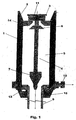
- the cylindrical basic body 1 of the filling device is provided with an end piece 2 which has a coupling means formed with a corresponding screw thread (FIG. Fig. 1 ).
- the filling device furthermore has a connection 10 for the supply and the discharge of printing media 16.
- printing medium compressed air is generally used on drilling platforms for easy availability.
- the external controllable compressed air source which is designed in particular as a pneumatic control unit, is then connected by means of compressed air hose to the terminal 10 of the filling device and secured against rotation.
- connection valve 10 for the compressed air is connected via a pressure channel with the gas-tight closed cylindrical space between the outer surface of the filling piston 9 and the inner surface of the piston chamber 5 m.
- the piston valve 4 arranged in the base body 1 and the hollow cylindrical filling piston 9 cooperating with the piston valve.
- the piston valve 4 comprises an inlet-side valve disk 6, which are arranged together with an outlet-side valve plug 7 at a certain distance from one another on a valve guide rod 8.
- the valve guide rod 8 extends on the inlet side through the filling opening 3 in the stop / valve seat 14 and is connected to a disc via which a restoring force for closing the valve disk 6 of the piston valve 4 is exerted by the valve return spring 11 disposed between the disk and the valve seat 14.
- valve plug 7 The arranged at the outlet end of the valve guide rod 8 valve plug 7 is dimensioned and provided on its circumference with inner sealing lips that it can penetrate into the opening of the hollow cylindrical filling piston 9 and this can close.
- the tubular filling piston 9 is itself arranged axially slidably in the piston chamber 5 and formed on the inlet side as an annular stop 12 with a groove, which closes gas-tight and media-tight with the inner wall of the piston chamber 5.
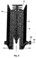
- the annular pump for supplying the drilling fluid to start in the state and the flowing through a pressure hose, the Topdrive and the Schon Western drilling fluid opens against the spring force of the valve return spring 11, the valve plate 6 and the filling opening 3 of the piston chamber 5 free.
- the drilling fluid passes through the piston chamber 5 into the tube opening of the filling piston 9 which forwards them into the drill train to be filled.
- the filling piston is, for example, pushed down by a flushing pressure of the drilling fluid of about 9 bar until the internal piston valve 4 releases the flow path into the hollow filling piston rod 9.
- the stroke of the filling piston should be about 60 cm here. However, other stroke parameters corresponding to the design requirements of other drilling rigs are also covered by this invention.
- the filling speed with which the drill string is now filled should preferably not exceed 250 l / min.
- a train should remain dry and the volume to be pumped pre-calculated and adjusted at the drilling fluid pumping device.
- valve plug 7 closes the hollow filling piston rod 9 and the valve disk 6 of the piston valve 4 is pressed against the valve seat 14.
- the closure of the filling opening 3 through the valve disk 6 is also supported by the return spring 11.
Landscapes
- Engineering & Computer Science (AREA)
- Geology (AREA)
- Mining & Mineral Resources (AREA)
- Life Sciences & Earth Sciences (AREA)
- General Life Sciences & Earth Sciences (AREA)
- Fluid Mechanics (AREA)
- Mechanical Engineering (AREA)
- Environmental & Geological Engineering (AREA)
- Physics & Mathematics (AREA)
- Geochemistry & Mineralogy (AREA)
- Earth Drilling (AREA)
- Branch Pipes, Bends, And The Like (AREA)
- Perforating, Stamping-Out Or Severing By Means Other Than Cutting (AREA)
- Auxiliary Devices For Machine Tools (AREA)
- Drilling And Boring (AREA)
Claims (11)
- Dispositif de remplissage servant à remplir un train de tiges ou une ou plusieurs foreuses avec du fluide de forage, constitué d'un corps de base cylindrique (1), entourant une chambre de piston (5) dotée d'au moins un orifice de remplissage (3) pour laisser passer le fluide de forage, d'un piston de remplissage (9) cylindrique creux servant à apporter le fluide de forage au train de tiges, voire aux foreuses, et glissant axialement dans la chambre de piston (5) du corps de base cylindrique, et d'une pièce d'extrémité (2) avec moyen de liaison, et servant à accoupler le train de tiges au Topdrive,
caractérisé en ce que l'orifice de remplissage (3) peut être obturé et que le piston de remplissage (9) cylindrique creux agit en liaison avec un distributeur à piston (4) engagé dans le corps creux et également disposé dans la chambre de piston pour pouvoir se déplacer axialement, de manière à ce que les positions d'ouverture et de fermeture servant à l'alimentation en fluide de forage puissent remplir leur fonction. - Dispositif de remplissage selon la revendication 1,
caractérisé en ce que le corps de base (1) est doté d'une vanne de connexion (10) servant à introduire ou à évacuer des milieux fluides ou gazeux, en particulier de l'air comprimé dans l'espace intérieur cylindrique de la chambre de piston (5) compris entre le corps de base (1) et le piston de remplissage (9), ce qui entraîne, sous l'effet de la pression, un déplacement du piston de remplissage (9) entre une position d'ouverture et de fermeture. - Dispositif de remplissage selon la revendication 2,
caractérisé en ce que le corps de base (1) comme le piston de remplissage (9) comportent des moyens de butée (14, 15), en particulier un siège de vanne (14) du côté admission et un guide de piston de remplissage (15) du côté évacuation, dont l'agencement permet de définir la course du piston de remplissage entre la position d'ouverture et la position de fermeture du piston de remplissage (9) dans le corps de base (1), sachant que le guide du piston de remplissage (15) est pourvu de dispositifs d'étanchéité (13) qui terminent l'ensemble et empêchent les fuites de fluide ou de gaz. - Dispositif de remplissage selon la revendication 3,
caractérisé en ce que le distributeur à piston (4) présente une tige de guide de piston (8) avec une tête de vanne (6) et au moins un bouchon de vanne (7) à une distance définie, celui-ci étant conçu pour pouvoir être introduit dans l'espace intérieur cylindrique creux du piston de remplissage (9) sans laisser passer de fluide, ce qui permet sa fermeture, et un ressort de rappel de vanne (11) du côté admission, disposé au-dessus du moyen de butée, voire du siège de vanne (14) de manière à ce que la tête de vanne (6) du côté admission puisse être obturée par le moyen de butée ou le siège de vanne sous la pression du ressort. - Dispositif de remplissage selon la revendication 4,
caractérisé en ce que le piston de remplissage du côté admission est doté d'une butée annulaire (12), laquelle présente au moins une rainure sur tout son pourtour pour loger des dispositifs d'étanchéité, en particulier une bague d'étanchéité, qui sépare le volume du milieu sous pression du fluide de forage qui s'écoule dans la chambre de piston (5), sachant que le bouchon de vanne (7) pouvant être introduit dans le piston de remplissage (9) présente également sur sa circonférence au moins un dispositif d'étanchéité permettant de séparer hermétiquement le piston de remplissage du train de tiges ou de la foreuse. - Procédé pour faire fonctionner un dispositif de remplissage selon une ou plusieurs revendications de 2 à 5,
caractérisé en ce que la pièce d'extrémité (2) du corps de base (1) du dispositif de remplissage est vissée au Topdrive du train de tiges de forage de manière à interdire le passage de fluide, que l'alimentation en milieu de pression (16) est reliée à la vanne de connexion (10), et que le remplissage des foreuses avec le fluide de forage est effectué pendant leur montage dans le train de tiges. - Procédé selon la revendication 6,
caractérisé en ce que, pour le remplissage d'une foreuse, le fluide de forage à introduire sous pression dans la foreuse, ouvre le distributeur à piston (4) et pénètre dans la chambre de piston (5) par l'orifice de remplissage (3), à la suite de quoi le piston de remplissage (9) cylindrique creux est repoussé vers le bas dans le corps de base (1) jusqu'à ce que le bouchon (7) du côté évacuation du distributeur à piston libère le chemin d'écoulement dans le piston de remplissage (9) et introduit la quantité prédéfinie de fluide de forage dans la foreuse via son orifice d'évacuation. - Procédé selon la revendication 7,
caractérisé en ce que la pression du fluide de forage à remplir est comprise entre 8 et 10 bars et que le chemin d'ouverture du piston de remplissage (9) mesure 60 cm, sachant que la vitesse de remplissage de la foreuse ou du train de tiges ne dépasse pas 250 l/min. - Procédé selon la revendication 6,
caractérisé en ce qu'à la clôture de l'opération de remplissage, il n'y a pas d'autre apport de fluide de forage via l'orifice de remplissage (3) et que le distributeur à piston (4) est fermé par compression de la tête de vanne (6) du côté admission contre le siège de vanne (14) étanche aux liquides au moyen du ressort de rappel de vanne (11). - Procédé selon l'une des revendications précédentes,
caractérisé en ce qu'au moyen d'une source externe de gaz sous pression, en particulier d'un compresseur fournissant de l'air comprimé, du gaz sous pression est conduit via la vanne de connexion (10) dans l'espace intérieur cylindrique entre le corps de base (1) et le piston de remplissage (9), entraînant le déplacement en position de fermeture du piston de remplissage (9), alors que le bouchon (7) est enfoncé à l'intérieur du piston de remplissage (9) et ferme celui-ci et que la tête de vanne (6) est maintenue contre le siège de vanne (14) par la butée annulaire (12) du piston de remplissage (9). - Procédé selon l'une des revendications précédentes,
caractérisé en ce que, pour éviter le débordement de fluide de forage, au moins une foreuse du train de tiges de forage n'est pas remplie et que le volume de remplissage à pomper est calculé avant le remplissage et contrôlé par le réglage de la pompe de remplissage en fluide de forage, de préférence une pompe annulaire.
Applications Claiming Priority (1)
| Application Number | Priority Date | Filing Date | Title |
|---|---|---|---|
| DE102004042956A DE102004042956B4 (de) | 2004-09-02 | 2004-09-02 | Verfahren und Fülleinrichtung zum Auffüllen von Bohrzügen mit Bohrflüssigkeit |
Publications (3)
| Publication Number | Publication Date |
|---|---|
| EP1632640A1 EP1632640A1 (fr) | 2006-03-08 |
| EP1632640A9 EP1632640A9 (fr) | 2007-06-27 |
| EP1632640B1 true EP1632640B1 (fr) | 2010-12-15 |
Family
ID=35207673
Family Applications (1)
| Application Number | Title | Priority Date | Filing Date |
|---|---|---|---|
| EP05006234A Not-in-force EP1632640B1 (fr) | 2004-09-02 | 2005-03-22 | Procédé et dispositif de remplissage d'un train de tiges de forage avec un fluide de forage |
Country Status (3)
| Country | Link |
|---|---|
| EP (1) | EP1632640B1 (fr) |
| AT (1) | ATE491860T1 (fr) |
| DE (3) | DE202004020879U1 (fr) |
Families Citing this family (9)
| Publication number | Priority date | Publication date | Assignee | Title |
|---|---|---|---|---|
| US8381823B2 (en) | 2006-02-08 | 2013-02-26 | Pilot Drilling Control Limited | Downhole tubular connector |
| US8316930B2 (en) | 2006-02-08 | 2012-11-27 | Pilot Drilling Control Limited | Downhole tubular connector |
| US8006753B2 (en) | 2006-02-08 | 2011-08-30 | Pilot Drilling Control Limited | Hydraulic connector apparatuses and methods of use with downhole tubulars |
| GB2435059B (en) | 2006-02-08 | 2008-05-07 | Pilot Drilling Control Ltd | A Drill-String Connector |
| US8002028B2 (en) | 2006-02-08 | 2011-08-23 | Pilot Drilling Control Limited | Hydraulic connector apparatuses and methods of use with downhole tubulars |
| US8047278B2 (en) | 2006-02-08 | 2011-11-01 | Pilot Drilling Control Limited | Hydraulic connector apparatuses and methods of use with downhole tubulars |
| GB2457317A (en) * | 2008-02-08 | 2009-08-12 | Pilot Drilling Control Ltd | A drill-string connector |
| GB2480402B8 (en) * | 2009-02-09 | 2014-04-09 | Pilot Drilling Control Ltd | A downhole tubular connector |
| CN113898210B (zh) * | 2021-12-13 | 2022-03-18 | 招远市昊润塑化有限公司 | 一种建筑缝隙的修补装置 |
Family Cites Families (7)
| Publication number | Priority date | Publication date | Assignee | Title |
|---|---|---|---|---|
| US4962819A (en) * | 1989-02-01 | 1990-10-16 | Drilex Systems, Inc. | Mud saver valve with replaceable inner sleeve |
| US5641021A (en) * | 1995-11-15 | 1997-06-24 | Halliburton Energy Services | Well casing fill apparatus and method |
| US5735348A (en) * | 1996-10-04 | 1998-04-07 | Frank's International, Inc. | Method and multi-purpose apparatus for dispensing and circulating fluid in wellbore casing |
| US5971079A (en) * | 1997-09-05 | 1999-10-26 | Mullins; Albert Augustus | Casing filling and circulating apparatus |
| US6059038A (en) * | 1998-02-26 | 2000-05-09 | Halliburton Energy Services, Inc. | Auto-fill sub |
| US6460620B1 (en) * | 1999-11-29 | 2002-10-08 | Weatherford/Lamb, Inc. | Mudsaver valve |
| CA2445870C (fr) * | 2001-04-30 | 2009-04-07 | Weatherford/Lamb, Inc. | Dispositif automatique de remplissage de tubage |
-
2004
- 2004-09-02 DE DE202004020879U patent/DE202004020879U1/de not_active Expired - Lifetime
- 2004-09-02 DE DE102004042956A patent/DE102004042956B4/de not_active Expired - Fee Related
-
2005
- 2005-03-22 EP EP05006234A patent/EP1632640B1/fr not_active Not-in-force
- 2005-03-22 DE DE502005010668T patent/DE502005010668D1/de active Active
- 2005-03-22 AT AT05006234T patent/ATE491860T1/de active
Also Published As
| Publication number | Publication date |
|---|---|
| DE502005010668D1 (de) | 2011-01-27 |
| EP1632640A1 (fr) | 2006-03-08 |
| DE202004020879U1 (de) | 2007-01-11 |
| EP1632640A9 (fr) | 2007-06-27 |
| DE102004042956A1 (de) | 2006-04-20 |
| ATE491860T1 (de) | 2011-01-15 |
| DE102004042956B4 (de) | 2013-06-27 |
Similar Documents
| Publication | Publication Date | Title |
|---|---|---|
| EP1632640B1 (fr) | Procédé et dispositif de remplissage d'un train de tiges de forage avec un fluide de forage | |
| DE60010647T2 (de) | Rohreinheit mit einer mehrzahl von auslässen zur verwendung in einem bohrloch und verfahren zum einführen einer solchen rohreinheit | |
| DE69735828T2 (de) | Verfahren und multifunktionale Vorrichtung zum Verteilen und Zirkulieren von Flüssigkeiten in Futterrohren | |
| DE60024650T2 (de) | Unterwasser-schmiervorrichtung | |
| DE69830328T2 (de) | Vorrichtung zur sandentfernung in einer unterwasserbohrung und gebrauch einer strahlpumpe zur sandentfernung | |
| DE3125035C2 (fr) | ||
| DE2735602C2 (de) | Vorrichtung und Verfahren zum Steuern des Mengenstroms durch eine Förderleitung und zur Injektion eines chemischen Mediums in die Förderleitung | |
| EP1731708B1 (fr) | Appareil de forage à marteau à percussion et procédé associé | |
| DE2652901A1 (de) | Vorrichtung und verfahren zur sicherung eines bohrloches | |
| DE3641521A1 (de) | Vorrichtung und verfahren zum durchdringen einer bohrlochwand in einem mit einer auskleidung versehenen bohrloch | |
| DE1927864B2 (de) | Vorrichtung zum einzementieren eines futterrohrstranges | |
| DE2938955A1 (de) | Kupplung fuer den austritt von steuerleitungen an bohrlochkoepfen | |
| DE69629692T2 (de) | Verfahren zur unterstützung der produktion | |
| DE202018006641U1 (de) | Fluidbetätigte Bohrvorrichtung | |
| DE60317550T2 (de) | Vorrichtung zur filtrierung von bohrschlamm | |
| DE2339391A1 (de) | Preventereinheit zur herstellung einer abdichtung zwischen einer verrohrung in einem bohrgestaenge beim tiefbohren unter druck | |
| DE10328609B3 (de) | Nassbohrwerkzeug, Bohranlage und Verfahren zum Niederbringen einer Bohrung im Boden | |
| DE102006059171B3 (de) | Bohrvorrichtung und Verfahren zum Erstellen einer Bohrung im Erdboden | |
| EP0331978A2 (fr) | Tige de forage pour marteau hydraulique de forage de fond de puits | |
| DE3304594A1 (de) | Einrichtung zum saeubern von bohrloechern | |
| DE4140317A1 (de) | Hydraulischer einzelstempel mit fuell-/raubventil und druckfluessigkeitsrueckfuehrung | |
| DE102009005514B4 (de) | Vorrichtung für eine Rohrtour eines geologischen Bohrlochs, Rohrtour, Verfahren zum Betreiben einer geologischen Bohranlage sowie Verfahren zum Herstellen einer Rohrtour für ein geologisches Bohrloch | |
| DE2730554C2 (de) | Bohreinrichtung für Umkehrspülung | |
| DE102019109486B4 (de) | Vorrichtung zum Erhöhen eines Drucks eines Arbeitsfluids für ein Bohrsystem | |
| DE3117763A1 (de) | Doppelt wirkende bohrloch-pumpe |
Legal Events
| Date | Code | Title | Description |
|---|---|---|---|
| PUAI | Public reference made under article 153(3) epc to a published international application that has entered the european phase |
Free format text: ORIGINAL CODE: 0009012 |
|
| AK | Designated contracting states |
Kind code of ref document: A1 Designated state(s): AT BE BG CH CY CZ DE DK EE ES FI FR GB GR HU IE IS IT LI LT LU MC NL PL PT RO SE SI SK TR |
|
| AX | Request for extension of the european patent |
Extension state: AL BA HR LV MK YU |
|
| 17P | Request for examination filed |
Effective date: 20060327 |
|
| AKX | Designation fees paid |
Designated state(s): AT BE BG CH CY CZ DE DK EE ES FI FR GB GR HU IE IS IT LI LT LU MC NL PL PT RO SE SI SK TR |
|
| 17Q | First examination report despatched |
Effective date: 20070620 |
|
| GRAP | Despatch of communication of intention to grant a patent |
Free format text: ORIGINAL CODE: EPIDOSNIGR1 |
|
| GRAS | Grant fee paid |
Free format text: ORIGINAL CODE: EPIDOSNIGR3 |
|
| GRAA | (expected) grant |
Free format text: ORIGINAL CODE: 0009210 |
|
| AK | Designated contracting states |
Kind code of ref document: B1 Designated state(s): AT BE BG CH CY CZ DE DK EE ES FI FR GB GR HU IE IS IT LI LT LU MC NL PL PT RO SE SI SK TR |
|
| REG | Reference to a national code |
Ref country code: CH Ref legal event code: EP Ref country code: GB Ref legal event code: FG4D Free format text: NOT ENGLISH |
|
| REG | Reference to a national code |
Ref country code: IE Ref legal event code: FG4D |
|
| REF | Corresponds to: |
Ref document number: 502005010668 Country of ref document: DE Date of ref document: 20110127 Kind code of ref document: P |
|
| REG | Reference to a national code |
Ref country code: NL Ref legal event code: VDEP Effective date: 20101215 |
|
| PG25 | Lapsed in a contracting state [announced via postgrant information from national office to epo] |
Ref country code: LT Free format text: LAPSE BECAUSE OF FAILURE TO SUBMIT A TRANSLATION OF THE DESCRIPTION OR TO PAY THE FEE WITHIN THE PRESCRIBED TIME-LIMIT Effective date: 20101215 |
|
| LTIE | Lt: invalidation of european patent or patent extension |
Effective date: 20101215 |
|
| PG25 | Lapsed in a contracting state [announced via postgrant information from national office to epo] |
Ref country code: FI Free format text: LAPSE BECAUSE OF FAILURE TO SUBMIT A TRANSLATION OF THE DESCRIPTION OR TO PAY THE FEE WITHIN THE PRESCRIBED TIME-LIMIT Effective date: 20101215 Ref country code: CY Free format text: LAPSE BECAUSE OF FAILURE TO SUBMIT A TRANSLATION OF THE DESCRIPTION OR TO PAY THE FEE WITHIN THE PRESCRIBED TIME-LIMIT Effective date: 20101215 Ref country code: BG Free format text: LAPSE BECAUSE OF FAILURE TO SUBMIT A TRANSLATION OF THE DESCRIPTION OR TO PAY THE FEE WITHIN THE PRESCRIBED TIME-LIMIT Effective date: 20110315 Ref country code: SE Free format text: LAPSE BECAUSE OF FAILURE TO SUBMIT A TRANSLATION OF THE DESCRIPTION OR TO PAY THE FEE WITHIN THE PRESCRIBED TIME-LIMIT Effective date: 20101215 Ref country code: SI Free format text: LAPSE BECAUSE OF FAILURE TO SUBMIT A TRANSLATION OF THE DESCRIPTION OR TO PAY THE FEE WITHIN THE PRESCRIBED TIME-LIMIT Effective date: 20101215 Ref country code: NL Free format text: LAPSE BECAUSE OF FAILURE TO SUBMIT A TRANSLATION OF THE DESCRIPTION OR TO PAY THE FEE WITHIN THE PRESCRIBED TIME-LIMIT Effective date: 20101215 |
|
| REG | Reference to a national code |
Ref country code: IE Ref legal event code: FD4D |
|
| PG25 | Lapsed in a contracting state [announced via postgrant information from national office to epo] |
Ref country code: IE Free format text: LAPSE BECAUSE OF FAILURE TO SUBMIT A TRANSLATION OF THE DESCRIPTION OR TO PAY THE FEE WITHIN THE PRESCRIBED TIME-LIMIT Effective date: 20101215 Ref country code: PT Free format text: LAPSE BECAUSE OF FAILURE TO SUBMIT A TRANSLATION OF THE DESCRIPTION OR TO PAY THE FEE WITHIN THE PRESCRIBED TIME-LIMIT Effective date: 20110415 Ref country code: CZ Free format text: LAPSE BECAUSE OF FAILURE TO SUBMIT A TRANSLATION OF THE DESCRIPTION OR TO PAY THE FEE WITHIN THE PRESCRIBED TIME-LIMIT Effective date: 20101215 Ref country code: GR Free format text: LAPSE BECAUSE OF FAILURE TO SUBMIT A TRANSLATION OF THE DESCRIPTION OR TO PAY THE FEE WITHIN THE PRESCRIBED TIME-LIMIT Effective date: 20110316 Ref country code: IS Free format text: LAPSE BECAUSE OF FAILURE TO SUBMIT A TRANSLATION OF THE DESCRIPTION OR TO PAY THE FEE WITHIN THE PRESCRIBED TIME-LIMIT Effective date: 20110415 Ref country code: ES Free format text: LAPSE BECAUSE OF FAILURE TO SUBMIT A TRANSLATION OF THE DESCRIPTION OR TO PAY THE FEE WITHIN THE PRESCRIBED TIME-LIMIT Effective date: 20110326 Ref country code: EE Free format text: LAPSE BECAUSE OF FAILURE TO SUBMIT A TRANSLATION OF THE DESCRIPTION OR TO PAY THE FEE WITHIN THE PRESCRIBED TIME-LIMIT Effective date: 20101215 |
|
| PG25 | Lapsed in a contracting state [announced via postgrant information from national office to epo] |
Ref country code: PL Free format text: LAPSE BECAUSE OF FAILURE TO SUBMIT A TRANSLATION OF THE DESCRIPTION OR TO PAY THE FEE WITHIN THE PRESCRIBED TIME-LIMIT Effective date: 20101215 Ref country code: SK Free format text: LAPSE BECAUSE OF FAILURE TO SUBMIT A TRANSLATION OF THE DESCRIPTION OR TO PAY THE FEE WITHIN THE PRESCRIBED TIME-LIMIT Effective date: 20101215 Ref country code: RO Free format text: LAPSE BECAUSE OF FAILURE TO SUBMIT A TRANSLATION OF THE DESCRIPTION OR TO PAY THE FEE WITHIN THE PRESCRIBED TIME-LIMIT Effective date: 20101215 |
|
| BERE | Be: lapsed |
Owner name: E.D. OIL TOOLS SERVICE RENTAL G.M.B.H. Effective date: 20110331 |
|
| PLBE | No opposition filed within time limit |
Free format text: ORIGINAL CODE: 0009261 |
|
| STAA | Information on the status of an ep patent application or granted ep patent |
Free format text: STATUS: NO OPPOSITION FILED WITHIN TIME LIMIT |
|
| PG25 | Lapsed in a contracting state [announced via postgrant information from national office to epo] |
Ref country code: MC Free format text: LAPSE BECAUSE OF NON-PAYMENT OF DUE FEES Effective date: 20110331 Ref country code: DK Free format text: LAPSE BECAUSE OF FAILURE TO SUBMIT A TRANSLATION OF THE DESCRIPTION OR TO PAY THE FEE WITHIN THE PRESCRIBED TIME-LIMIT Effective date: 20101215 |
|
| REG | Reference to a national code |
Ref country code: CH Ref legal event code: PL |
|
| 26N | No opposition filed |
Effective date: 20110916 |
|
| GBPC | Gb: european patent ceased through non-payment of renewal fee |
Effective date: 20110322 |
|
| REG | Reference to a national code |
Ref country code: FR Ref legal event code: ST Effective date: 20111130 |
|
| PG25 | Lapsed in a contracting state [announced via postgrant information from national office to epo] |
Ref country code: BE Free format text: LAPSE BECAUSE OF NON-PAYMENT OF DUE FEES Effective date: 20110331 Ref country code: IT Free format text: LAPSE BECAUSE OF FAILURE TO SUBMIT A TRANSLATION OF THE DESCRIPTION OR TO PAY THE FEE WITHIN THE PRESCRIBED TIME-LIMIT Effective date: 20101215 |
|
| REG | Reference to a national code |
Ref country code: DE Ref legal event code: R097 Ref document number: 502005010668 Country of ref document: DE Effective date: 20110916 |
|
| PG25 | Lapsed in a contracting state [announced via postgrant information from national office to epo] |
Ref country code: LI Free format text: LAPSE BECAUSE OF NON-PAYMENT OF DUE FEES Effective date: 20110331 Ref country code: FR Free format text: LAPSE BECAUSE OF NON-PAYMENT OF DUE FEES Effective date: 20110331 Ref country code: DE Free format text: LAPSE BECAUSE OF NON-PAYMENT OF DUE FEES Effective date: 20111001 Ref country code: CH Free format text: LAPSE BECAUSE OF NON-PAYMENT OF DUE FEES Effective date: 20110331 |
|
| REG | Reference to a national code |
Ref country code: DE Ref legal event code: R119 Ref document number: 502005010668 Country of ref document: DE Effective date: 20111001 |
|
| PG25 | Lapsed in a contracting state [announced via postgrant information from national office to epo] |
Ref country code: GB Free format text: LAPSE BECAUSE OF NON-PAYMENT OF DUE FEES Effective date: 20110322 |
|
| REG | Reference to a national code |
Ref country code: AT Ref legal event code: MM01 Ref document number: 491860 Country of ref document: AT Kind code of ref document: T Effective date: 20110322 |
|
| PG25 | Lapsed in a contracting state [announced via postgrant information from national office to epo] |
Ref country code: AT Free format text: LAPSE BECAUSE OF NON-PAYMENT OF DUE FEES Effective date: 20110322 |
|
| PG25 | Lapsed in a contracting state [announced via postgrant information from national office to epo] |
Ref country code: LU Free format text: LAPSE BECAUSE OF NON-PAYMENT OF DUE FEES Effective date: 20110322 |
|
| PG25 | Lapsed in a contracting state [announced via postgrant information from national office to epo] |
Ref country code: TR Free format text: LAPSE BECAUSE OF FAILURE TO SUBMIT A TRANSLATION OF THE DESCRIPTION OR TO PAY THE FEE WITHIN THE PRESCRIBED TIME-LIMIT Effective date: 20101215 |
|
| PG25 | Lapsed in a contracting state [announced via postgrant information from national office to epo] |
Ref country code: HU Free format text: LAPSE BECAUSE OF FAILURE TO SUBMIT A TRANSLATION OF THE DESCRIPTION OR TO PAY THE FEE WITHIN THE PRESCRIBED TIME-LIMIT Effective date: 20101215 |