EP1632416A1 - Foldable perambulator - Google Patents
Foldable perambulator Download PDFInfo
- Publication number
- EP1632416A1 EP1632416A1 EP04020939A EP04020939A EP1632416A1 EP 1632416 A1 EP1632416 A1 EP 1632416A1 EP 04020939 A EP04020939 A EP 04020939A EP 04020939 A EP04020939 A EP 04020939A EP 1632416 A1 EP1632416 A1 EP 1632416A1
- Authority
- EP
- European Patent Office
- Prior art keywords
- backrest
- stroller
- stroller according
- holder
- carriage
- Prior art date
- Legal status (The legal status is an assumption and is not a legal conclusion. Google has not performed a legal analysis and makes no representation as to the accuracy of the status listed.)
- Withdrawn
Links
Images


Classifications
-
- B—PERFORMING OPERATIONS; TRANSPORTING
- B62—LAND VEHICLES FOR TRAVELLING OTHERWISE THAN ON RAILS
- B62B—HAND-PROPELLED VEHICLES, e.g. HAND CARTS OR PERAMBULATORS; SLEDGES
- B62B7/00—Carriages for children; Perambulators, e.g. dolls' perambulators
- B62B7/04—Carriages for children; Perambulators, e.g. dolls' perambulators having more than one wheel axis; Steering devices therefor
- B62B7/06—Carriages for children; Perambulators, e.g. dolls' perambulators having more than one wheel axis; Steering devices therefor collapsible or foldable
- B62B7/08—Carriages for children; Perambulators, e.g. dolls' perambulators having more than one wheel axis; Steering devices therefor collapsible or foldable in the direction of, or at right angles to, the wheel axis
-
- B—PERFORMING OPERATIONS; TRANSPORTING
- B62—LAND VEHICLES FOR TRAVELLING OTHERWISE THAN ON RAILS
- B62B—HAND-PROPELLED VEHICLES, e.g. HAND CARTS OR PERAMBULATORS; SLEDGES
- B62B7/00—Carriages for children; Perambulators, e.g. dolls' perambulators
- B62B7/04—Carriages for children; Perambulators, e.g. dolls' perambulators having more than one wheel axis; Steering devices therefor
- B62B7/06—Carriages for children; Perambulators, e.g. dolls' perambulators having more than one wheel axis; Steering devices therefor collapsible or foldable
- B62B7/062—Coupling unit between front wheels, rear wheels and handle
-
- B—PERFORMING OPERATIONS; TRANSPORTING
- B62—LAND VEHICLES FOR TRAVELLING OTHERWISE THAN ON RAILS
- B62B—HAND-PROPELLED VEHICLES, e.g. HAND CARTS OR PERAMBULATORS; SLEDGES
- B62B7/00—Carriages for children; Perambulators, e.g. dolls' perambulators
- B62B7/04—Carriages for children; Perambulators, e.g. dolls' perambulators having more than one wheel axis; Steering devices therefor
- B62B7/12—Carriages for children; Perambulators, e.g. dolls' perambulators having more than one wheel axis; Steering devices therefor convertible, e.g. into children's furniture or toy
- B62B7/123—Carriages for children; Perambulators, e.g. dolls' perambulators having more than one wheel axis; Steering devices therefor convertible, e.g. into children's furniture or toy from seat to bed
-
- B—PERFORMING OPERATIONS; TRANSPORTING
- B62—LAND VEHICLES FOR TRAVELLING OTHERWISE THAN ON RAILS
- B62B—HAND-PROPELLED VEHICLES, e.g. HAND CARTS OR PERAMBULATORS; SLEDGES
- B62B9/00—Accessories or details specially adapted for children's carriages or perambulators
- B62B9/10—Perambulator bodies; Equipment therefor
- B62B9/102—Perambulator bodies; Equipment therefor characterized by details of the seat
-
- B—PERFORMING OPERATIONS; TRANSPORTING
- B62—LAND VEHICLES FOR TRAVELLING OTHERWISE THAN ON RAILS
- B62B—HAND-PROPELLED VEHICLES, e.g. HAND CARTS OR PERAMBULATORS; SLEDGES
- B62B2205/00—Hand-propelled vehicles or sledges being foldable or dismountable when not in use
- B62B2205/04—Hand-propelled vehicles or sledges being foldable or dismountable when not in use box-shaped in folded position
-
- B—PERFORMING OPERATIONS; TRANSPORTING
- B62—LAND VEHICLES FOR TRAVELLING OTHERWISE THAN ON RAILS
- B62B—HAND-PROPELLED VEHICLES, e.g. HAND CARTS OR PERAMBULATORS; SLEDGES
- B62B2501/00—Manufacturing; Constructional features
- B62B2501/06—Materials used
- B62B2501/065—Plastics
Definitions
- the device relates to a collapsible stroller with a hinged folding device according to the independent claim.
- Collapsible stroller are space-saving storable and transportable and therefore offer a useful alternative to rigid stroller.
- a variety of collapsible strollers is already known.
- the folding mechanism is designed as a shearing mechanism in most.
- An example of such a stroller is disclosed in EP 0 908 730.
- shear mechanisms have the disadvantage that the length of the stroller when folding is not reduced. In particular, if the stroller is to be taken as a baggage, that is a problem.
- the angles between the shear joints are coupled together so that not any adjustments between the seat, the backrest and the brackets for the front and rear wheels are possible.
- the stroller consists of a seat element, a backrest, a first holder for at least one front wheel and a second holder for at least two rear wheels and a sliding device.
- a folding mechanism on which the seat element, the backrest and the first and the second holder are each secured on one side. All elements are attached to the folding mechanism so that they can be pivoted about them, the folding mechanism has swivel joints for stepless pivoting of the individual elements.
- front and rear wheels do not determine the direction of the carriage or the direction in which the child is looking. It is e.g. conceivable that the sliding device is pivotable so that the viewing direction of the child in or against the direction of movement of the car can be selected. Here are those wheels called front wheels, which are located at the feet of the child.
- reinforced plastics eg with stabilizing ribbing or gas injection or with glass fiber filling, drawn or welded aluminum or steel profiles and foam cushions with fabric or synthetic fiber coatings are suitable for producing a child-friendly product.
- the backrest can be designed as a plastic shell with a fabric cover.
- a backrest is advantageous in which only the frame is formed of rigid material.
- the fabric cover can be attached to this frame and forms the actual backrest. As a result, the car can be folded flat.
- the fabric cover with the help of zip or Velcro fasteners or snaps can be made adjustable in depth.
- the seat can be made as a fabric seat in a frame made of metal or plastic.
- the brackets for the front and rear wheels can also be designed only as a frame or as a rigid shell.
- the stroller has exactly two front and two rear wheels. It is also advantageous if at least the front wheels are freely rotatably mounted, which simplifies the steering of the car.
- the folding device has two basic positions. In the first position the stroller is in an operating position, in the second position it is folded.
- the stroller is advantageously fixed at least in the first position of the stroller.
- the person skilled in many means for fixing known how the stroller can be fixed in the operating position For example, stops, clamps, latches or wedges can hold the elements in place.
- stops, clamps, latches or wedges can hold the elements in place.
- further means for fixing the carriage in the operating position are also encompassed by the present invention.
- a release mechanism is preferably provided, by means of which at least two of the elements seat, backrest, first and second bracket or pusher are released together or simultaneously from the operating position. Particularly advantageous all elements are solved together or simultaneously. In this case, all elements can be released from the operating position with a handle and thus easily bring in the folded position.
- the trigger mechanism must be operated with both hands.
- the risk of the triggering mechanism being inadvertently, e.g. by another child, can be further reduced, if a certain amount of force to actuate the trigger mechanism is necessary.
- the triggering mechanism may e.g. be stabilized with a spring.
- the triggering mechanism comprises a Bowden cable.
- the trigger e.g. a lever
- the trigger be attached to a well-accessible for an adult person of the car, for example, at the upper end of the backrest.
- the force used to release directed to the means for fixing the car, which are usually arranged on the joint itself.
- the seat element, the backrest and the first and second holder are preferably arranged approximately parallel to each other projecting from the folding device.
- the stroller is in the folded position only about half as long as in the operating position. Due to the highest possible parallel arrangement of the individual elements of the stroller in the folded position is also very compact, compared to conventional stroller relatively flat and therefore space-saving stowed.
- the elements are arranged approximately in a star shape around the folding device.
- the angle between the individual elements can be freely adjusted and adjust the seat and backrest angle individually. But it is also conceivable that each of the elements can be individually adjusted between a predetermined number of positions and the angle thereby are gradually varied.
- the hinges of the seat element, the backrest and the first and second holder are arranged in alignment on a rotation axis.
- This axis of rotation is not necessarily continuous form, it can also exist as a geometric product of several axes of individual hinges.
- the elements of the carriage are arranged in the folded position approximately parallel to each other, the elements can be of different sizes.
- the support for the front wheels may consist of two struts, between which the seat is arranged in the folded position.
- individual ones of the elements, e.g. the backrest so be attached to the folding mechanism, that the pivot point is not on the extension of the backrest, but slightly shifted. This can be achieved for example by a bent attachment of the elements on the hinge.
- the hinges of the individual elements discs, disc sections or rotatable levers which are rotatably mounted on a common axis.
- At least two of the discs, disc sections or levers are advantageously provided by a common locking arrangement, preferably with a common locking element, for example a Wedge, locked, in particular by the wedge can be inserted into a locking groove of the discs.
- the discs can all have the same diameter. It is also possible that individual ones of the disks or disk sections have a narrower diameter, so that they are first released when the locking element is released.
- the detent groove in one disk may be less deep than in another, and a wedge may be correspondingly stepped, in that the disks are released in a predetermined order.
- a locking element may be provided a clamping device which locks the discs, disc sections or lever.
- the clamping device may be arranged, for example, analogous to the bicycle brake horseshoe-shaped around the discs, disc sections or lever around. When the elements are locked, the clamping device abuts at least partially on the discs, disc sections or levers. This can e.g. be favored by the discs, disc sections or lever with projections, e.g. Bolt or pins are provided, which engage in the clamping device.
- the clamping device is opened.
- a horseshoe-shaped clamping device that means that the opening is widened.
- the diameter of the clamping device is larger, and the discs, disc sections or levers lose contact with the clamping device.
- an advantage of a disc arrangement is that individual ones of the elements may be attached to the discs such that the extension of the member does not pass through the pivot point of the disc. This corresponds to a tangential attachment of the element to the corresponding disc. Tangential is here only related to the direction, but does not specify the location at which the respective element is attached to the corresponding disc.
- the tangential attachment is a preferred alternative or supplement to the cranked attachment of elements to the pivot and allows for improved parallel alignment of the elements in the folded position of the carriage.
- a joint consisting of relatively large discs is more stable than a conventional pivot.
- the hinges of the various elements are arranged in alignment on two axes of rotation. This embodiment is particularly advantageous because the elements in the folded position can be aligned almost perfectly parallel to each other. An embodiment in which the elements are aligned on three axes of rotation is also conceivable.
- Some or all of the elements can be provided with stops for limiting the pivoting angle. As a result, the pivoting movement is in a controlled range. Unwanted flaps of elements in an unexpected and unwieldy direction is thus prevented.
- the stops are given by a locking disc.
- a locking disc This is useful if the elements are attached to turntables.
- Each of these discs may be provided with a pin which runs in a longitudinal groove of the locking disc.
- the longitudinal groove extends parallel to the circumference of the disc over an angular portion of the disc. So that the stability of the locking disc is granted, the longitudinal groove advantageously extends in the radial direction no further than over half of the radius.
- the closer to the locking disc turntables may have a longitudinal groove through which the pin of the outer disc is guided to the locking disc.
- the pivoting angle of the outer pane is also influenced by the inner pane.
- the discs can all be guided in the same longitudinal groove of the locking disc.
- the locking disc has a plurality of longitudinal groove sections, each section leading a pin. An advantage of these arrangements is that the diameter of all disks can be selected the same size.
- the outer disc at least in places may have a larger diameter than the inner disc.
- the pin of the outer disk can then be guided past the inner disk and in a radially outer groove of the locking disk.
- Another, particularly preferred embodiment of means for limiting the pivotal movement of individual elements is the wedging of the elements against each other. This can be done, for example, when the pin of a disc is guided in a longitudinal groove of an adjacent disc.
- the disc to which the holder for the rear wheels is attached have a longitudinal groove. In this longitudinal groove, a pin can be guided, which is attached to the disc for the support of the front wheels. As a result, the relative movement between the first and the second holder can be restricted. This means that the two elements can be pivoted against each other only one predetermined angle range.
- the pivotal movement of individual elements can also be restricted in a particularly simple manner by connecting them with flexible means.
- These flexible means may be bands or cords, or rods with at least one joint. This type of restriction of the movement is particularly useful for the two brackets of the front and rear wheels, because, for example, in the connection of the two brackets a support network could be placed.
- the stroller on means for fixing the carriage in the folded position.
- These means may have latching noses, clamps, straps or other elements known to those skilled in the art.
- projections are attached to the backrest of the baby carriage. These projections support the stroller in the folded position, so that an upright position of the car is possible. The parallel elements of the car then stand vertically from the ground.
- the projections can also be used advantageously in the operating position of the car, for example umbrellas, shopping bags, jackets, etc. can be hung. It is also possible that purchased items for the stroller are attachable to it, such as a parasol or a holder for a bottle.
- a footrest is attached to the first holder. This increases the comfort and safety for the child.
- the pusher can be attached to the backrest. It is also conceivable that it is attached directly to the folding device and can also be pivoted about it. It is advantageous if the pusher can be changed in length, e.g. by being attached to rails or to telescopically intermeshing pipes. Alternatively, the device can also be attached by up to 180 ° pivotally mounted on the backrest. The pivoting and / or the length adjustment facilitate different sized people to push the car comfortably.
- a 180 ° pivoting pusher may also be connected to the release mechanism for releasing the carriage from the first position.
- the release of the means for fixing the carriage is triggered only by the pivoting of the pusher. This can for example be done by a Bowden train is connected via a shaft with the pusher. The movement of the pusher tightens the Bowden cable and releases the car's fixation.
- the sliding device is advantageously held in position in this embodiment by further means for fixing during operation.
- the elements are arranged in the folded position so that the underside of the seat element and the holder of the front wheels form the outer sides of the carriage.
- the advantage is that the seat and the inside of the backrest are not exposed to environmental influences and tend to stay clean.
- the seat element has a fold-out or extendable extension, so that the length of the seat in the unfolded or extended state corresponds to the length of the backrest. This protects both surfaces over their entire extent.
- the top of the seat and the inside of the backrest in the folded position of the car can form the outside.
- the disadvantage here is that the seat of the child is easily soiled.
- An advantage of this arrangement, however, is that the folding of the stroller is particularly easy. After releasing the fixation, the seat and the back rest on the brackets of the front and rear wheels, while these are still preferably in the operating position. Thus, the car is already folded halfway until it has to be lifted for the first time.
- the stroller can be set in the operating position between a lying position and a sitting position.
- the seating position corresponds to the above-mentioned approximately star-shaped arrangement of the individual elements.
- the backrest In the lying position, the backrest can be brought into an approximately horizontal position.
- the extension of the seat is swung or pulled out and serves as an additional foot rest for the child lying.
- this extension can be provided with a fixed or foldable stop, which stabilizes the feet of the child down.
- At least one carrying handle is attached laterally to at least one of the elements, which further simplifies the transport of the folded wagon.
- a carrying handle may also be provided in the transverse direction of the carriage.
- a carrying handle between the seat and the backrest may be provided, which comes to light when folding the cart.
- This carrying handle is then located approximately on the axis of rotation of the folding mechanism. In the operating position such a carrying handle is hidden under the seat. This is aesthetically beneficial.
- folding such a carrying handle facilitates the final folding of the car.
- the seat and the backrest have come to rest on the two brackets of the front and rear wheels, the carrying handle is free between them.
- the carriage can then be lifted on the carrying handle, with the holders moving together until they lie against one another.
- the car is then in the folded position.
- the car can be folded particularly flat when the front and / or rear wheels of the car are mounted pivotable about 90 ° to the car. This is particularly advantageous if the wheels have a large diameter.
- the wheels are laterally slightly beyond the brackets out. It is particularly advantageous if the two brackets are not the same length from its axis of rotation for suspending the wheels, for example, those for the rear wheels is slightly shorter than those for the front wheels. The brackets can then be put together. Since the wheels are beyond the brackets, they do not hinder the movement.
- brackets If the difference in length of the two brackets is greater than the radius of the wheels, they find space in the longitudinal direction of the brackets side by side, the brackets are stopped not by the wheels but by other elements.
- the front and / or rear wheels may be arranged to protrude beyond the remaining elements in the folded position. When transporting the car, they can be used to pull or push the car.
- protective covers can be included. These should reasonably cover at least the corners, as they are most exposed to shocks.
- the protective covers can also enclose the whole car, which is suitable if it should be stored for a long time. For transport protective coatings are more advantageous that release at least one carrying handle. For heavier cars, it is advantageous that the front and / or rear wheels and the pusher are excluded from the protective cover, so that the car can be pulled or pushed as a trolley case.
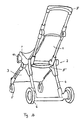
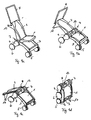
- Fig. 1a the collapsible stroller is shown in the operating position.
- the seat element 1, the backrest 2, the first holder 3 for the front wheels 5 and the second holder 4 for the rear wheels 6 are arranged approximately in a star shape around the folding device 7.
- the pusher 8 is fixed to the seat back 2.
- a footrest 9 is attached for the safety and comfort of the child. To fold this footrest can be folded.
- a fold-out extension 10 is attached, which is unfolded in the folded position of the baby carriage. If the stroller is placed in a lying position, the extension serves as a footrest for the child.
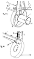
- a shutter 11 is mounted, which fixes in the carriage in the folded position.
- a brake 12 is also attached, with which the rear wheels of the car are blocked.
- the brake 12 via cables with handles (not shown) may be attached to the pusher 8 and operated by hands.
- the arrows indicate the movements of the individual elements when adjusting.
- the wheels 5, 6 or the brackets 3, 4 of the car can be mounted on springs (not shown) that absorb when driving due to bumps occurring in the way bumps.
- the two brackets 3 and 4 can be connected to cross connections 16 (shown in Fig. 5), which stabilizes the carriage and protects against unwanted folding. This is particularly advantageous on uneven roads or when crossing roads with curbs advantage.
- a transport network (not shown) can be attached.
- a sun and / or umbrella may be attached, which can preferably be unfolded like a fan.
- a belt system (not shown) may be attached to the backrest 2 and the seat element 1, with which the child is secured while driving in the car.
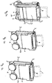
- FIGS. 2a and 2b show two views of the baby carriage according to FIG. 1a in the folded-up position.
- the seat element 1 and the first holder 3 form the outside of the baby carriage.
- the holder 3 is designed as a reinforced shell, so that the stroller in the folded state has stable outsides.
- the rear wheels 6 are in hubcaps (not shown), which are folded by 90 ° against the car.
- the footrest 9 is rotatably mounted and is rotated in the folded state against the car. This makes the whole car very compact and stable.
- the shutter 11 prevents the carriage from opening undesirably.
- the pusher 8 is rotatably mounted on the backrest 2 so that it is rotated by 180 ° against the back during folding and is suitable for carrying the car.
- the front wheels 5 are in the folded position on the other elements out.
- the car can also be pushed or pulled in the folded position. This is particularly easy to implement when the pusher 8 is adjustable in length. This is indicated by dotted lines.
- the pusher 8 may be additionally equipped with a counterpart 8 'at the lower end. In the folded state, this counterpart 8 'can be used to carry or even push or pull the car.
- the counterpart 8 'in the folded state assumes the function of the sliding device 8, which is illustrated in FIG. 2c.
- the telescopic extension of the counterpart 8 'for pushing or pulling the car is indicated by dotted lines.
- the pusher 8 can be folded or retracted and is not visible in Fig. 2c.
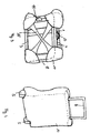
- the seat element 1 and the holder 3 also form the outer sides of the stroller in the folded state in this stroller.
- a possible embodiment for protective coatings 14 can be seen.
- the protective coatings 14 are made of a soft, preferably waterproof material such as synthetic fibers and can be padded with foam inside.
- Each two diagonally opposite protective coatings 14 are connected to an elastic band 15, which allows a simple and stable attachment of the coatings 14.
- the baby carriage is also attached to the second bracket 4, a carrying handle 3, on which the carriage can be easily transported in the folded state.
- the protective cover 14 has openings for the front wheels 5 and the pusher 8. For packing the stroller in the protective cover 14 this can with a tear or Velcro fastener (not shown) be opened.
- This protective cover 14 is preferably made of a stable material.
- a folding bag (not shown) may be attached to the stroller, e.g. on the bracket 3 for the front wheels.
- the protective cover can be stowed, alternatively, toys, diapers or other items can be carried there.
- FIG. 5 How the stroller is folded, can be seen from Fig. 5.
- the carriage In partabb. b) the extension 10 of the seat member 1 has been folded up and the seat element 1 against the backrest 2 folded.
- the sliding device 8 has been pivoted by 180 ° against the backrest 2.
- backrest 2 and seat element 1 were folded against the holder 4.
- the footrest 9 is folded into the holder 3.
- the two brackets 3 and 4 are folded against each other.
- the crossbar 16 must also be folded up.
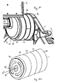
- Fig. 6 is a schematic representation of a portion of the folding device 7. On the carriage, two such, mutually mirrored arrangements are arranged on the same geometric axis.
- the seat 1 is connected to the roller 7.1, the backrest 2 with the roller 7.2 and the first holder 3 with the roller 7.3.
- the second holder 4 is connected to the roller 7.4, which in turn is connected via the bridge 7.5 with the roller 7.6. Over the bridge 7.5, the two central rollers 7.7 are thus held against each other in position.
- the locking of the individual rollers can be different.
- the two rollers 7.4 and 7.6 are fixed to the rollers 7.7.
- the remaining rollers are rotatably mounted on the rollers 7.7 and can be fixed by means of brakes. Brakes in the form of mutually rotatable brake shoes within the rotating rollers are preferred. These can be locked by a spring, which are tensioned by means of pushbuttons in the hubs of the rollers 7.7.
- drum brakes various forms of drum brakes can be used.
- the rollers are 7.7 at the same time the brake shoes of the drum brake and pressed by a conical screw to the inner wall of the roller to be determined. Since it must be used to rotate the screws force, it is also ensured that a child can not solve the brakes.
- the locking is done with a pin brake, pins being pressed through holes in the rollers 7.7 against the inner wall of the roller to be determined.
- the locking effect can be improved if the inner walls of the rollers are provided with indentations in which the pins fit.
- the individual elements are not continuously adjustable against each other.
- the pins can be connected via a spring mechanism with a push button, which is mounted in the hubs of the rollers 7.7.
- the lock can also take place outside the rollers.
- On the same type can also be the seat element 1 and the backrest 2 are connected, these transverse rods then can serve as armrests.
- this form of locking does not allow continuous adjustment of the angle between the individual elements. Depending on the number of teeth in the profile but different angles can be adjusted.
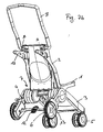
- FIGS. 7a-7c, 8a-8c An alternative preferred embodiment of the stroller according to the invention is shown in FIGS. 7a-7c, 8a-8c.
- the folding mechanism 7 has only one axis of rotation A (FIGS. 11a, 11b).
- the axis of rotation A is not formed continuously but is the geometric product of two rotatable about this axis disc bundles.
- the seat 1, the backrest 2, the first bracket 3 for the front wheels 5 and the second bracket 4 for the rear wheels 6 are made of sturdy plastic.
- the weight of this stroller is significantly reduced compared to conventional metal cars and is about 6 kg.
- the pusher 8 is also made of plastic, but could also be made of light metal, e.g. Be made of aluminum.
- the wheels 5 and 6 are conventional hard rubber wheels with aluminum rims.
- the rear wheels 6 are firmly held in the forward orientation, while the front wheels 5 are rotatable about a vertical axis.
- the front wheels 5 can be locked in the forward orientation.
- a lever (not shown) is provided for each wheel, with which a pin is guided in the wheel suspension and locked there.
- the holder 3 is not made of a plastic plate, but has only two longitudinal struts. On the bracket 3, a footrest 9 is also attached. The seat 1 is so narrow that it finds space between the longitudinal struts of the holder 3.
- projections 17 On the backrest 2 rearwardly facing projections 17 are attached. At these projections 17 purchased parts such as shopping nets, umbrellas or umbrellas, beverage bottle holders or the like can be attached. But they are also suitable, for. Hang jackets or shopping bags on it. As can be seen from Fig. 8c, the stroller is supported in the folded position on these projections.
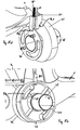
- Fig. 7b of the stroller is shown obliquely from behind. Under the seat 1 and the backrest 2, a carrying handle 13 is visible. In the folded position of the stroller is carried on this handle 13.
- the brake 12 blocks the rear wheels 6. This prevents unwanted rolling of the car.
- release lever 18 are visible to release the fixation of the car. These levers 18 are arranged symmetrically with respect to the vertical carriage center and must be operated simultaneously, so that the fixation of the car can be solved. It is not enough to operate only one of the levers 18 to release the fixation of the car. This symmetrical arrangement reduces the risk that the fixation will be accidentally released. The entire triggering mechanism is described in conjunction with FIG.
- the release lever 18 solve the fixation of all elements of the car.
- FIGS. 9a-9d The collapsing process is explained in FIGS. 9a-9d.
- Fig. 9a is the stroller in the operating position, the wheels 5 are locked in the forward direction.
- the two trigger levers 18 see Fig. 7b are operated simultaneously, all elements of the carriage are released at the same time.
- the brackets 3 and 4 are prevented from moving apart as described below. By the weight of the car they are pushed apart and initially remain in the operating position, while the seat 1 and the backrest 2 are already folded.
- the outer sides of the carriage in the folded state form the backrest 2 (FIG. 8a) and the seat 1 with the holder 3 (FIG. 8b).
- the holder 3 is slightly cranked to a disc 73 (see Fig. 15f, 15g) attached.
- the total thickness of the carriage in the folded state is insignificantly greater than the diameter of the rear wheels 6.
- Fig. 11a the discs without the other elements of the carriage are shown.
- the shuttering 70 ' is also hidden.
- the disc 70 is fixedly connected to a cylindrical, concentrically arranged cylinder shaft 75.
- the shaft 75 is made of a metal tube.
- the remaining discs 71-73 are rotatably mounted.
- the axis of rotation A passes through the center of the cylinder tube 75.
- the disc 74 is firmly connected to the shaft 75.
- the disc 70 is provided with recesses 76.
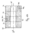
- FIG. 11b shows a section along the axis A from FIG. 11a.
- the shaft 75 on which the discs 71-74 are mounted.
- the disc 73 to which the holder 3 for the front wheels 5 is attached, has two pins 77a and 78a. These pins 77a and 78a are guided in the longitudinal grooves 77b and 78b of the discs 71 for the seat 1 and 74 for the holder 4 of the rear wheels 6.
- FIGS. 12c and 12e which show a top view of the disks 71 and 74, can be seen more clearly.
- the pins 77a and 78a are guided so that the swing angle is relatively limited between the seat 1, the bracket 3, and the bracket 4.
- the grooves 77b, 78b are chosen so that the holder 3 is fixed in the operating position by the pins 77a and 78a in the grooves 77b and 78b. That is, the pin 77a in the groove 77b is at the top stop and the pin 78a ( Figure 11b) in the groove 78b is at the opposite bottom stop when the carriage is in the operative position.
- the remaining discs are fixed with a wedge 80 ( Figures 14a and 14b).
- the disc 74 is fixedly connected to the tube 75 and thus to the disc 70.
- the discs 70, 71 and 72 each have a locking groove 79.0, 79.1 and 79.2 as a counterpart for the fixing wedge 80.
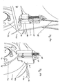
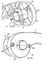
- FIG. 7b One side of the triggering mechanism is shown in FIG. The second side is mirror-symmetrically attached to the other side of the backrest 2 (FIG. 7b). For unlocking to take place, both levers 18 must be actuated at the same time.
- the lever 18 is fixed to a holder 20, which is guided in a rail 19. At this bracket 20 is also a continuation 21 of the pusher 8 is attached.
- a compression spring 24 presses the holder 20 against the outside of the backrest 2. The compression spring 24 is used for additional protection of the lever 18 secured in the operating position. It is thus a certain amount of force necessary to actuate the lever 18. The strength required is so great that a child in the game can not operate both levers at the same time.
- the pusher 8 By releasing the bolt 22 from the groove 23, the pusher 8 is released and is freely rotatable about an axis through the spring center. To fold the cart, the user gives the pusher 8 a small shock and lets it fall on the inside of the backrest 2.
- the Bowden cable 25 is guided around the bolt 26 and is fixed in the projection 27 on the bracket 20.
- the horizontal pulling movement of the lever 18 is transferred via the Bowden train 25 in a vertical pulling movement.
- the force is directed to the wedge 80 ( Figures 14a and 14b). By moving the lever so the wedge 80 is raised. Thus, all elements of the car are released with a triggering mechanism.
- the wedge 80 is visible in Figs. 14a and 14b.
- Fig. 14a the backrest 2 is inserted with the disc 72.
- Fig. 14b these two elements are hidden.
- the Bowden cable 25 is guided along the backrest 2 to the wedge 80.
- the wedge 80 is pressed with a compression spring 81 down into the locking grooves 79.0, 79.1 and 79.2 of the discs 70, 71 and 72. In the operating position, these discs are thus fixed by the wedge.
- Fig. 15a-15i the folding device of the stroller according to Fig. 7a-7c is shown in detail in a perspective view.
- Fig. 15a shows one half of the entire joint.
- the plastic casing 70 ' is hidden.
- the discs 70 to 74 are visible side by side.
- the wedge 80 holds the discs 70-74 in the operative position.
- the same arrangement is mirror-symmetrical. The discs can only be unlocked when the wedge 80 is released on both sides of the cart.
- FIG. 15b shows the view of the disc 72 from the outside of the carriage.
- the disc 72 is visible from the inside, ie from the center of the baby carriage.
- the disc 72 is rotatably mounted on the cylinder shaft 75.
- the backrest 2 is firmly connected to the disc 72. When the wedge 80 is pulled out of the groove 79.2, the disc 72 and thus the backrest 2 is folded around the shaft 75.
- Fig. 15d the discs 70 and 71 are shown in a view from the center of the car ago.
- Disk 70 is with the cylinder shaft 75 firmly welded.
- Disk 71 is rotatable about the shaft 75.
- Both disks 70 and 71 are fixed by the wedge 80 in the grooves 79.0 and 79.1.
- the compression spring 81 pushes the wedge 80 into the groove 79.0 and 79.1.
- the seat 1, which is fixedly connected to the disc 71, is thus held in the operating position.
- Fig. 15e the discs 71 and 72 are visible from the outside of the carriage.
- the wedge 80 holds both discs 71 and 72 in operative position.
- the longitudinal grooves 77b which is mounted in the disc 71.
- two longitudinal grooves 77b are provided, in each of which a bolt 77a (FIG. 15f) runs.
- FIGS. 15f and 15g the disks 70 and 73 can be seen in interaction.
- FIG. 15f shows the two disks 70 and 73 in a view from the center of the carriage.
- the disc 73 is connected to the holder 3 for the front wheels 5.
- the disc 73 has no locking groove for the wedge and is accordingly not fixed directly by the wedge 80.
- the bolts 77a and 78a on both sides of the disc 73 serve to limit the pivot angle of the disc 73 on the one hand and for fixing the disc 73 on the other.
- the bolts 77a are located on a stop of the longitudinal grooves 77b and the bolts 78a on the opposite stop of the longitudinal grooves 78b.
- the disc 73 is thus fixed in the operative position by the adjacent discs 71 and 74, which in turn are held in position by the wedge 80.
- Fig. 15g the discs 70 and 73 are shown from the outside of the carriage forth.
- the two bolts 78a which run in the longitudinal grooves 78b (Fig. 15h).
- the bracket 3 for the front wheels does not protrude radially from the axis of rotation A ( Figures 11a, 11b), which is determined by the central axis of the cylinder 75, but slightly displaced in the tangential direction.
- the holder 3 can be folded with high accuracy parallel to the remaining elements of the baby carriage.
- the bracket 3 is slightly cranked attached to the disc 73. This can be seen from the fact that the holder 3 is guided in a slight arc to the disk 73.
- Fig. 15h and 15i the two discs 70 and 74 are shown.
- Fig. 15h one sees the two discs 70 and 74 in a view from the center of the carriage ago, in Fig. 15i, they are shown from the outside of the car ago.
- the disc 74 is fixedly connected to the shaft 75, in this example riveted with her.
- the disc 74 is indirectly fixed by the wedge 80, which engages in the groove 79.0 of the disc 70.
- Fig. 15i is further seen that the holder 4 (analogous to the holder 3, Fig. 15g) is not radial to the axis of rotation A (Fig. 11a, 11b), which passes through the central axis of the cylinder 75 is defined.
- FIG. 15g it is noticeable that the holder 4 is offset with respect to the holder 3 on the opposite side of the axis A. If the two brackets 3 and 4 folded against each other, they are almost perfectly aligned parallel to each other. The car can thus be folded to save space.
Abstract
Description
Die Vorrichtung betrifft einen zusammenklappbaren Kinderwagen mit einer aus Drehgelenken bestehenden Klappvorrichtung gemäss dem unabhängigen Patentanspruch.The device relates to a collapsible stroller with a hinged folding device according to the independent claim.
Zusammenklappbare Kinderwagen sind Platz sparend aufbewahrbar und transportierbar und bieten deshalb eine sinnvolle Alternative zu starren Kinderwagen. Eine Vielzahl von zusammenklappbaren Kinderwagen ist bereits bekannt. Der Klappmechanismus ist bei den meisten als Schermechanismus ausgebildet. Ein Beispiel für so einen Kinderwagen ist in EP 0 908 730 offenbart. Schermechanismen haben aber den Nachteil, dass die Länge des Kinderwagens beim zusammenklappen nicht verkleinert wird. Insbesondere, wenn der Kinderwagen als Fluggepäck mitgenommen werden soll, ist das ein Problem. Ausserdem sind die Winkel zwischen den Schergelenken aneinander gekoppelt, so dass nicht beliebige Einstellungen zwischen der Sitzfläche, der Rückenlehne und den Halterungen für die Vorder- und Hinterräder möglich sind.Collapsible stroller are space-saving storable and transportable and therefore offer a useful alternative to rigid stroller. A variety of collapsible strollers is already known. The folding mechanism is designed as a shearing mechanism in most. An example of such a stroller is disclosed in EP 0 908 730. But shear mechanisms have the disadvantage that the length of the stroller when folding is not reduced. In particular, if the stroller is to be taken as a baggage, that is a problem. In addition, the angles between the shear joints are coupled together so that not any adjustments between the seat, the backrest and the brackets for the front and rear wheels are possible.
Aus DE 196 54 569 ist ein zusammenklappbarer Kinderwagen bekannt, bei dem die Neigung der Rückenlehne verstellt werden kann, ohne dass die Neigung der Sitzfläche verändert wird. Die Klappmechanik dieses Kinderwagens ist aber aufwendig und weist den gleichen Nachteil auf, wie übliche Schermechaniken: Die Länge des Kinderwagens im zusammengeklappten Zustand ist nicht kleiner als im Betriebszustand.From DE 196 54 569 a collapsible stroller is known in which the inclination of the backrest can be adjusted without the inclination of the seat is changed. However, the folding mechanism of this pushchair is complex and has the same disadvantage as conventional shearing mechanisms: The length of the pushchair in the folded state is not smaller than in the operating state.
Es ist die Aufgabe der Erfindung, einen zusammenklappbaren Kinderwagen zu schaffen, der die Nachteile des Bekannten vermeidet, der sich insbesondere klein zusammenlegen lässt, vorzugsweise als Handgepäck im Flugzeug oder Platz sparend im Auto mitgenommen werden kann und dennoch für das Kind individuell einstellbar ist und sich zudem durch einfache Herstellung und Handhabung auszeichnet.It is the object of the invention to provide a collapsible stroller, which avoids the disadvantages of the known, which in particular can be folded small, preferably as hand luggage on the plane or save space in the car can be taken and yet individually adjustable for the child is and is also characterized by ease of manufacture and handling.
Diese Aufgabe wird mit einem Kinderwagen mit einer aus Drehgelenken bestehenden Klappmechanik gemäss dem unabhängigen Patentanspruch gelöst.This object is achieved with a stroller with a hinged hinge mechanism according to the independent claim.
Der Kinderwagen besteht aus einem Sitzelement, einer Rückenlehne, einer ersten Halterung für mindestens ein Vorderrad und einer zweiten Halterung für mindestens zwei Hinterräder und einer Schiebevorrichtung. Weiter weist er eine Klappmechanik auf, an der das Sitzelement, die Rückenlehne sowie die erste und die zweite Halterung jeweils einseitig befestigt sind. Alle Elemente sind so an der Klappmechanik befestigt, dass sie um diese geschwenkt werden können, wobei die Klappmechanik Drehgelenke zum stufenlosen Verschwenken der einzelnen Elemente aufweist.The stroller consists of a seat element, a backrest, a first holder for at least one front wheel and a second holder for at least two rear wheels and a sliding device. Next, it has a folding mechanism on which the seat element, the backrest and the first and the second holder are each secured on one side. All elements are attached to the folding mechanism so that they can be pivoted about them, the folding mechanism has swivel joints for stepless pivoting of the individual elements.
Die Bezeichnungen Vorder- bzw. Hinterräder legen weder die Schieberichtung des Wagens noch die Blickrichtung des Kindes fest. Es ist z.B. denkbar, dass die Schiebevorrichtung derart schwenkbar ist, dass die Blickrichtung des Kindes in oder entgegen der Bewegungsrichtung des Wagens gewählt werden kann. Hier werden jene Räder als Vorderräder bezeichnet, welche sich bei den Füssen des Kindes befinden.The names front and rear wheels do not determine the direction of the carriage or the direction in which the child is looking. It is e.g. conceivable that the sliding device is pivotable so that the viewing direction of the child in or against the direction of movement of the car can be selected. Here are those wheels called front wheels, which are located at the feet of the child.
Zur Herstellung des Kinderwagens können verschiedene Materialien in verschiedenen Kombinationen verwendet werden. Insbesondere verstärkte Kunststoffe, z.B. mit stabilisierender Verrippung bzw. Gasinjektion oder mit Glasfaserfüllung, gezogene oder geschweisste Aluminium- oder Stahlprofile und Schaumstoffkissen mit Stoff- oder Kunstfaserüberzügen eignen sich zur Herstellung eines kinderfreundlichen Produkts.For the production of the baby carriage different materials can be used in different combinations. In particular, reinforced plastics, eg with stabilizing ribbing or gas injection or with glass fiber filling, drawn or welded aluminum or steel profiles and foam cushions with fabric or synthetic fiber coatings are suitable for producing a child-friendly product.
Die Rückenlehne kann als Schale aus Kunststoff mit einem Stoffüberzug ausgebildet sein. Vorteilhaft ist jedoch eine Rückenlehne, bei der nur der Rahmen aus starrem Material geformt ist. Der Stoffbezug kann an diesem Rahmen befestigt werden und bildet die eigentliche Lehne. Dadurch kann der Wagen flacher zusammengeklappt werden. Ausserdem kann der Stoffüberzug mit Hilfe von Reiss- oder Klettverschlüssen oder Druckknöpfen in der Tiefe verstellbar gefertigt sein. Analog kann auch der Sitz als Stoffsitz in einem Rahmen aus Metall oder Kunststoff gefertigt sein.The backrest can be designed as a plastic shell with a fabric cover. However, a backrest is advantageous in which only the frame is formed of rigid material. The fabric cover can be attached to this frame and forms the actual backrest. As a result, the car can be folded flat. In addition, the fabric cover with the help of zip or Velcro fasteners or snaps can be made adjustable in depth. Similarly, the seat can be made as a fabric seat in a frame made of metal or plastic.
Die Halterungen für die Vorder- und die Hinterräder können ebenfalls nur als Rahmen oder als starre Schale ausgebildet sein.The brackets for the front and rear wheels can also be designed only as a frame or as a rigid shell.
Vorzugsweise hat der Kinderwagen genau zwei Vorder- und zwei Hinterräder. Vorteilhaft ist des weiteren, wenn zumindest die Vorderräder frei drehbar befestigt sind, was das Lenken des Wagens vereinfacht.Preferably, the stroller has exactly two front and two rear wheels. It is also advantageous if at least the front wheels are freely rotatably mounted, which simplifies the steering of the car.
Die Klappvorrichtung weist zwei grundsätzliche Positionen auf. In der ersten Position befindet sich der Kinderwagen in einer Betriebsstellung, in der zweiten Position ist er zusammengeklappt.The folding device has two basic positions. In the first position the stroller is in an operating position, in the second position it is folded.
Der Kinderwagen ist vorteilhaft mindestens in der ersten Position des Kinderwagens fixierbar. Dem Fachmann sind viele Mittel zur Fixierung bekannt, wie der Kinderwagen in der Betriebsstellung fixiert werden kann. Beispielsweise können Anschläge, Klemmen, Rastnasen oder Keile die Elemente in ihrer Position halten. Weitere Mittel zum Fixieren des Wagens in der Betriebsposition sind durch die vorliegende Erfindung aber ebenfalls umfasst.The stroller is advantageously fixed at least in the first position of the stroller. The person skilled in many means for fixing known how the stroller can be fixed in the operating position. For example, stops, clamps, latches or wedges can hold the elements in place. However, further means for fixing the carriage in the operating position are also encompassed by the present invention.
Damit die einfache Handhabung gewährleistet ist, ist vorzugsweise ein Auslösemechanismus vorgesehen, mittels welchem mindestens zwei von den Elementen Sitz, Rückenlehne, erste und zweite Halterung oder Schiebevorrichtung gemeinsam oder gleichzeitig aus der Betriebsstellung gelöst werden. Besonders vorteilhaft werden alle Elemente gemeinsam bzw. gleichzeitig gelöst. In diesem Fall lassen sich alle Elemente aus der Betriebsstellung mit einem Handgriff lösen und somit einfach in die zusammengeklappte Position bringen.So that the ease of use is ensured, a release mechanism is preferably provided, by means of which at least two of the elements seat, backrest, first and second bracket or pusher are released together or simultaneously from the operating position. Particularly advantageous all elements are solved together or simultaneously. In this case, all elements can be released from the operating position with a handle and thus easily bring in the folded position.
Um die Sicherheit zu erhöhen ist es vorteilhaft, wenn der Auslösemechanismus mit beiden Händen betätigt werden muss. Die Gefahr dass der Auslösemechanismus unabsichtlich, z.B. durch ein weiteres Kind, betätigt wird, kann weiter reduziert werden, wenn ein gewisser Kraftaufwand zum Betätigen des Auslösemechanismus notwendig ist. Dazu kann der Auslösemechanismus z.B. mit einer Feder stabilisiert werden.To increase safety, it is advantageous if the trigger mechanism must be operated with both hands. The risk of the triggering mechanism being inadvertently, e.g. by another child, can be further reduced, if a certain amount of force to actuate the trigger mechanism is necessary. For this, the triggering mechanism may e.g. be stabilized with a spring.
Besonders bevorzugt umfasst der Auslösemechanismus einen Bowden-Zug. Dadurch kann der Auslöser, z.B. ein Hebel, an einer für eine erwachsene Person gut zugänglichen Stelle des Wagens angebracht werden, beispielsweise am oberen Ende der Rückenlehne. Über den Bowden-Zug wird die zum Lösen aufgewendete Kraft zu den Mitteln zur Fixierung des Wagens geleitet, welche üblicherweise am Gelenk selber angeordnet sind.Most preferably, the triggering mechanism comprises a Bowden cable. Thereby the trigger, e.g. a lever, be attached to a well-accessible for an adult person of the car, for example, at the upper end of the backrest. About the Bowden-train, the force used to release directed to the means for fixing the car, which are usually arranged on the joint itself.
In der zusammengeklappten Position sind das Sitzelement, die Rückenlehne sowie die erste und zweite Halterung vorzugsweise etwa parallel zueinander von der Klappvorrichtung abstehend angeordnet. Somit ist der Kinderwagen in der zusammengeklappten Position nur etwa halb so lang wie in der Betriebsposition. Durch die höchstmöglich parallele Anordnung der einzelnen Elemente ist der Kinderwagen in der zusammengeklappten Position ausserdem sehr kompakt, im Vergleich zu herkömmlichen Kinderwagen relativ flach und deshalb platzsparend verstaubar.In the folded position, the seat element, the backrest and the first and second holder are preferably arranged approximately parallel to each other projecting from the folding device. Thus, the stroller is in the folded position only about half as long as in the operating position. Due to the highest possible parallel arrangement of the individual elements of the stroller in the folded position is also very compact, compared to conventional stroller relatively flat and therefore space-saving stowed.
In der Betriebsstellung sind die Elemente ungefähr sternförmig um die Klappvorrichtung herum angeordnet. Vorzugsweise lassen sich die Winkel zwischen den einzelnen Elementen frei einstellen und die Sitz- und Lehnenneigung individuell anpassen. Es ist aber auch denkbar, dass jedes der Elemente einzeln zwischen einer vorgegebenen Anzahl von Positionen verstellen lässt und die Winkel dadurch stufenweise variierbar sind.In the operating position, the elements are arranged approximately in a star shape around the folding device. Preferably, the angle between the individual elements can be freely adjusted and adjust the seat and backrest angle individually. But it is also conceivable that each of the elements can be individually adjusted between a predetermined number of positions and the angle thereby are gradually varied.
In einer bevorzugten Ausführungsform sind die Drehgelenke des Sitzelements, der Rückenlehne sowie der ersten und zweiten Halterung auf einer Drehachse fluchtend angeordnet. Diese Drehachse ist nicht zwingend durchgehend auszubilden, sie kann auch als geometrisches Produkt mehrerer Achsen von einzelnen Drehgelenken bestehen.In a preferred embodiment, the hinges of the seat element, the backrest and the first and second holder are arranged in alignment on a rotation axis. This axis of rotation is not necessarily continuous form, it can also exist as a geometric product of several axes of individual hinges.
Damit die Elemente des Wagens in der zusammengeklappten Position etwa parallel zueinander angeordnet sind, können die Elemente unterschiedlich gross sein. Beispielsweise kann die Halterung für die Vorderräder aus zwei Streben bestehen, zwischen welchen der Sitz in der zusammengeklappten Position angeordnet ist. Alternativ oder zusätzlich können einzelne der Elemente, z.B. die Rückenlehne, so am Klappmechanismus befestigt sein, dass der Drehpunkt nicht auf der Verlängerung der Lehne liegt, sondern leicht verschoben ist. Dies kann beispielsweise durch eine gekröpfte Befestigung der Elemente am Drehgelenk erreicht werden.So that the elements of the carriage are arranged in the folded position approximately parallel to each other, the elements can be of different sizes. For example, the support for the front wheels may consist of two struts, between which the seat is arranged in the folded position. Alternatively or additionally, individual ones of the elements, e.g. the backrest, so be attached to the folding mechanism, that the pivot point is not on the extension of the backrest, but slightly shifted. This can be achieved for example by a bent attachment of the elements on the hinge.
In einer bevorzugten Ausführungsform weisen die Drehgelenke der einzelnen Elemente Scheiben, Scheibenabschnitte oder drehbare Hebel auf, die an einer gemeinsamen Achse drehbar gelagert sind. Mindestens zwei der Scheiben, Scheibenabschnitte oder Hebel werden vorteilhaft durch eine gemeinsame Arretierungsanordnung, vorzugsweise mit einem gemeinsamen Arretierungselement, z.B. einem Keil, arretiert, insbesondere indem der Keil in eine Rastnut der Scheiben eingeführt werden kann. Die Scheiben können alle den gleichen Durchmesser aufweisen. Es ist ebenso möglich, dass einzelne der Scheiben bzw. Scheibenabschnitte einen schmaleren Durchmesser haben, so dass diese beim Lösen des Arretierungselements zuerst gelöst werden. Alternativ kann die Rastnut in einer Scheibe weniger tief sein als in einer anderen und ein Keil entsprechend treppenförmig ausgeprägt sein, dass die Scheiben in einer vorgegebenen Reihenfolge gelöst werden.In a preferred embodiment, the hinges of the individual elements discs, disc sections or rotatable levers which are rotatably mounted on a common axis. At least two of the discs, disc sections or levers are advantageously provided by a common locking arrangement, preferably with a common locking element, for example a Wedge, locked, in particular by the wedge can be inserted into a locking groove of the discs. The discs can all have the same diameter. It is also possible that individual ones of the disks or disk sections have a narrower diameter, so that they are first released when the locking element is released. Alternatively, the detent groove in one disk may be less deep than in another, and a wedge may be correspondingly stepped, in that the disks are released in a predetermined order.
Als alternatives Arretierungselement kann eine Klemmvorrichtung vorgesehen sein, welche die Scheiben, Scheibenabschnitte oder Hebel arretiert. Die Klemmvorrichtung kann beispielsweise analog zur Fahrradbremse hufeisenförmig um die Scheiben, Scheibenabschnitte oder Hebel herum angeordnet sein. Wenn die Elemente arretiert sind, liegt die Klemmvorrichtung zumindest teilweise an den Scheiben, Scheibenabschnitten oder Hebeln an. Dies kann z.B. begünstigt werden, indem die Scheiben, Scheibenabschnitte oder Hebel mit Vorsprüngen, z.B. Bolzen oder Stiften versehen sind, die in die Klemmvorrichtung greifen.As an alternative locking element may be provided a clamping device which locks the discs, disc sections or lever. The clamping device may be arranged, for example, analogous to the bicycle brake horseshoe-shaped around the discs, disc sections or lever around. When the elements are locked, the clamping device abuts at least partially on the discs, disc sections or levers. This can e.g. be favored by the discs, disc sections or lever with projections, e.g. Bolt or pins are provided, which engage in the clamping device.
Zum Lösen der Arretierung wird die Klemmvorrichtung geöffnet. Bei einer hufeisenförmigen Klemmvorrichtung heisst das, dass Öffnung verbreitert wird. Dadurch wird der Durchmesser der Klemmvorrichtung grösser, und die Scheiben, Scheibenabschnitte oder Hebel verlieren den Kontakt zur Klemmvorrichtung.To release the lock, the clamping device is opened. In a horseshoe-shaped clamping device that means that the opening is widened. As a result, the diameter of the clamping device is larger, and the discs, disc sections or levers lose contact with the clamping device.
Ein Vorteil einer Scheiben-Anordnung ist zusätzlich, dass einzelne der Elemente so an den Scheiben befestigt sein können, dass die Verlängerung des Elements nicht durch den Drehpunkt der Scheibe läuft. Das entspricht einer tangentialen Befestigung des Elements an der entsprechenden Scheibe. Tangential ist hier nur auf die Richtung bezogen, legt aber nicht den Ort fest, an welchem das jeweilige Element an der entsprechenden Scheibe befestigt ist.In addition, an advantage of a disc arrangement is that individual ones of the elements may be attached to the discs such that the extension of the member does not pass through the pivot point of the disc. This corresponds to a tangential attachment of the element to the corresponding disc. Tangential is here only related to the direction, but does not specify the location at which the respective element is attached to the corresponding disc.
Die tangentiale Befestigung ist eine bevorzugte Alternative oder Ergänzung zur gekröpften Befestigung von Elementen am Drehgelenk und erlaubt eine verbesserte parallele Ausrichtung der Elemente in der zusammengeklappten Position des Wagens. Ausserdem ist ein Gelenk, das aus relativ grossen Scheiben besteht, stabiler als ein herkömmliches Drehgelenk.The tangential attachment is a preferred alternative or supplement to the cranked attachment of elements to the pivot and allows for improved parallel alignment of the elements in the folded position of the carriage. In addition, a joint consisting of relatively large discs is more stable than a conventional pivot.
In einer anderen bevorzugten Ausführungsform sind die Drehgelenke der verschiedenen Elemente auf zwei Drehachsen fluchtend angeordnet. Diese Ausführungsform ist besonders vorteilhaft, weil die Elemente in der zusammengeklappten Position so beinahe perfekt parallel gegeneinander ausgerichtet werden können. Eine Ausführung, bei der die Elemente auf drei Drehachsen fluchten, ist ebenfalls denkbar.In another preferred embodiment, the hinges of the various elements are arranged in alignment on two axes of rotation. This embodiment is particularly advantageous because the elements in the folded position can be aligned almost perfectly parallel to each other. An embodiment in which the elements are aligned on three axes of rotation is also conceivable.
Einzelne oder alle der Elemente können mit Anschlägen zur Begrenzung des Schwenkwinkels versehen werden. Dadurch verläuft die Schwenkbewegung in einem kontrollierten Bereich. Unerwünschtes Klappen von Elementen in eine unerwartete und unhandliche Richtung wird damit verhindert.Some or all of the elements can be provided with stops for limiting the pivoting angle. As a result, the pivoting movement is in a controlled range. Unwanted flaps of elements in an unexpected and unwieldy direction is thus prevented.
Besonders bevorzugt sind die Anschläge durch eine Verriegelungsscheibe gegeben. Dies ist dann sinnvoll, wenn die Elemente an Drehscheiben befestigt sind. Jede dieser Scheiben kann mit einem Stift versehen sein, der in einer Längsnut der Verriegelungsscheibe läuft. Die Längsnut verläuft parallel zum Umfang der Scheibe über einen Winkelabschnitt der Scheibe. Damit die Stabilität der Verriegelungsscheibe gewährt ist, erstreckt sich die Längsnut in radialer Richtung vorteilhaft nicht weiter als über die Hälfte des Radius.Particularly preferably, the stops are given by a locking disc. This is useful if the elements are attached to turntables. Each of these discs may be provided with a pin which runs in a longitudinal groove of the locking disc. The longitudinal groove extends parallel to the circumference of the disc over an angular portion of the disc. So that the stability of the locking disc is granted, the longitudinal groove advantageously extends in the radial direction no further than over half of the radius.
Über die Länge der Längsnut ist der Schwenkwinkel des Elements beschränkt. Falls mehrere Elemente an der Verriegelungsscheibe anschlagen sollen, können die näher bei der Verriegelungsscheibe liegenden Drehscheiben eine Längsnut aufweisen, durch welche der Stift der äusseren Scheibe zur Verriegelungsscheibe geführt wird. Dadurch wird der Schwenkwinkel der äusseren Scheibe auch durch die innere Scheibe beeinflusst. Die Scheiben können alle in der gleichen Längsnut der Verriegelungsscheibe geführt werden. Es ist aber auch denkbar, dass die Verriegelungsscheibe mehrere Längsnut-Abschnitte aufweist, wobei jeder Abschnitt einen Stift führt. Vorteilhaft an diesen Anordnungen ist, dass der Durchmesser aller Scheiben gleich gross gewählt werden kann.Over the length of the longitudinal groove of the pivot angle of the element is limited. If several elements are to strike against the locking disc, the closer to the locking disc turntables may have a longitudinal groove through which the pin of the outer disc is guided to the locking disc. As a result, the pivoting angle of the outer pane is also influenced by the inner pane. The discs can all be guided in the same longitudinal groove of the locking disc. However, it is also conceivable that the locking disc has a plurality of longitudinal groove sections, each section leading a pin. An advantage of these arrangements is that the diameter of all disks can be selected the same size.
Alternativ kann die äussere Scheibe zumindest stellenweise einen grösseren Durchmesser haben als die innere Scheibe. Der Stift der äusseren Scheibe kann dann an der inneren Scheibe vorbei und in einer radial weiter aussen liegenden Längsnut der Verriegelungsscheibe geführt werden.Alternatively, the outer disc at least in places may have a larger diameter than the inner disc. The pin of the outer disk can then be guided past the inner disk and in a radially outer groove of the locking disk.
Eine weitere, besonders bevorzugte Ausführungsform von Mitteln zum Beschränken der Schwenkbewegung einzelner Elemente ist das Verkeilen der Elemente gegen einander. Dies kann beispielsweise geschehen, wenn der Stift einer Scheibe in einer Längsnut einer benachbarten Scheibe geführt wird. Beispielsweise kann die Scheibe, an welcher die Halterung für die Hinterräder befestigt ist, eine Längsnut aufweisen. In dieser Längsnut kann ein Stift geführt werden, welcher an der Scheibe für die Halterung der Vorderräder befestigt ist. Dadurch lässt sich die Relativbewegung zwischen der ersten und der zweiten Halterung einschränken. Das bedeutet, dass die beiden Elemente nur ein einem vorgegebenen Winkelbereich gegeneinander geschwenkt werden können.Another, particularly preferred embodiment of means for limiting the pivotal movement of individual elements is the wedging of the elements against each other. This can be done, for example, when the pin of a disc is guided in a longitudinal groove of an adjacent disc. For example, the disc to which the holder for the rear wheels is attached, have a longitudinal groove. In this longitudinal groove, a pin can be guided, which is attached to the disc for the support of the front wheels. As a result, the relative movement between the first and the second holder can be restricted. This means that the two elements can be pivoted against each other only one predetermined angle range.
Selbstverständlich kann das gleiche Prinzip auch auf andere Elemente angewandt werden.Of course, the same principle can also be applied to other elements.
Besonders einfach lässt sich die Schwenkbewegung von einzelnen Elementen auch einschränken, indem diese mit flexiblen Mitteln verbunden werden. Diese flexiblen Mittel können Bänder oder Schnüre sein, oder auch Stäbe mit wenigstens einem Gelenk. Diese Art der Einschränkung der Bewegung ist insbesondere für die beiden Halterungen der Vorder- und Hinterräder sinnvoll, weil beispielsweise in die Verbindung der beiden Halterungen ein Tragnetz gelegt werden könnte.The pivotal movement of individual elements can also be restricted in a particularly simple manner by connecting them with flexible means. These flexible means may be bands or cords, or rods with at least one joint. This type of restriction of the movement is particularly useful for the two brackets of the front and rear wheels, because, for example, in the connection of the two brackets a support network could be placed.
Vorteilhaft weist der Kinderwagen weiter Mittel zum Fixieren des Wagens in der zusammengeklappten Position auf. Diese Mittel können Rastnasen, Klemmen, Gurte oder andere dem Fachmann bekannte Elemente aufweisen. Durch das Fixieren des Kinderwagens in der zusammengeklappten Position kann dieser einfach und sicher transportiert werden. Dies ist insbesondere dann wichtig, wenn der Wagen von Hand getragen werden soll.Advantageously, the stroller on means for fixing the carriage in the folded position. These means may have latching noses, clamps, straps or other elements known to those skilled in the art. By fixing the stroller in the folded position this can be transported easily and safely. This is especially important if the car is to be carried by hand.
In einem bevorzugten Ausführungsbeispiel sind an der Rückenlehne des Kinderwagens Vorsprünge angebracht. Diese Vorsprünge stützen den Kinderwagen in der zusammengeklappten Position, so dass ein aufrechter Stand des Wagens möglich ist. Die parallel angeordneten Elemente des Wagens stehen dann senkrecht vom Boden ab. Die Vorsprünge können ausserdem auch in der Betriebsstellung des Wagens vorteilhaft genutzt werden, z.B. können daran Schirme, Einkaufstaschen, Jacken etc. aufgehängt werden. Es ist auch möglich, dass Zukaufartikel für den Kinderwagen daran befestigbar sind, z.B. ein Sonnenschirm oder eine Halterung für eine Trinkflasche.In a preferred embodiment, projections are attached to the backrest of the baby carriage. These projections support the stroller in the folded position, so that an upright position of the car is possible. The parallel elements of the car then stand vertically from the ground. The projections can also be used advantageously in the operating position of the car, for example umbrellas, shopping bags, jackets, etc. can be hung. It is also possible that purchased items for the stroller are attachable to it, such as a parasol or a holder for a bottle.
Bevorzugter Weise ist eine Fussstütze an der ersten Halterung angebracht. Dies erhöht den Komfort und die Sicherheit für das Kind.Preferably, a footrest is attached to the first holder. This increases the comfort and safety for the child.
Die Schiebevorrichtung kann an der Rückenlehne befestigt sein. Ebenso ist es denkbar, dass sie direkt an der Klappvorrichtung befestigt ist und ebenfalls um diese geschwenkt werden kann. Vorteilhaft ist es, wenn die Schiebevorrichtung in ihrer Länge verändert werden kann, z.B. indem sie an Schienen oder an teleskopartig ineinander greifenden Rohren befestigt ist. Alternativ kann die Vorrichtung auch um bis zu 180° schwenkbar an der Rückenlehne angebracht sein. Das Schwenken und/oder die Längenregulierung erleichtern verschieden grossen Personen, den Wagen bequem zu schieben.The pusher can be attached to the backrest. It is also conceivable that it is attached directly to the folding device and can also be pivoted about it. It is advantageous if the pusher can be changed in length, e.g. by being attached to rails or to telescopically intermeshing pipes. Alternatively, the device can also be attached by up to 180 ° pivotally mounted on the backrest. The pivoting and / or the length adjustment facilitate different sized people to push the car comfortably.
Eine um 180° schwenkbare Schiebevorrichtung kann ausserdem mit dem Auslösemechanismus zum Lösen des Wagens aus der ersten Position verbunden sein. Bei einer besonders vorteilhaften Ausführung wird das Lösen der Mittel zur Fixierung des Wagens erst durch das Umschwenken der Schiebevorrichtung ausgelöst. Dies kann beispielsweise geschehen, indem ein Bowden-Zug über eine Welle mit der Schiebevorrichtung verbunden ist. Durch die Bewegung der Schiebevorrichtung wird der Bowden-Zug angespannt und löst die Fixierung des Wagens. Die Schiebevorrichtung wird in diesem Ausführungsbeispiel vorteilhaft durch weitere Mittel zur Fixierung während dem Betrieb in Position gehalten.A 180 ° pivoting pusher may also be connected to the release mechanism for releasing the carriage from the first position. In a particularly advantageous embodiment, the release of the means for fixing the carriage is triggered only by the pivoting of the pusher. This can for example be done by a Bowden train is connected via a shaft with the pusher. The movement of the pusher tightens the Bowden cable and releases the car's fixation. The sliding device is advantageously held in position in this embodiment by further means for fixing during operation.
In einer möglichen Ausführungsform sind die Elemente in der zusammengeklappten Position so angeordnet, dass die Unterseite des Sitzelementes und die Halterung der Vorderräder die Aussenseiten des Wagens bilden. Vorteilhaft ist daran, dass die Sitzfläche und die Innenseite der Rückenlehne Umwelteinflüssen nicht so stark ausgesetzt sind und eher sauber bleiben. Besonders vorteilhaft ist es dazu, wenn das Sitzelement eine ausklappbare oder ausfahrbare Verlängerung besitzt, so dass die Länge der Sitzfläche im ausgeklappten oder ausgefahrenen Zustand der Länge der Rückenlehne entspricht. Damit sind beide Flächen über ihre ganze Ausdehnung hinweg geschützt.In one possible embodiment, the elements are arranged in the folded position so that the underside of the seat element and the holder of the front wheels form the outer sides of the carriage. The advantage is that the seat and the inside of the backrest are not exposed to environmental influences and tend to stay clean. Especially advantageous it is when the seat element has a fold-out or extendable extension, so that the length of the seat in the unfolded or extended state corresponds to the length of the backrest. This protects both surfaces over their entire extent.
Alternativ können auch die Oberseite des Sitzes und die Innenseite der Rückenlehne in der zusammengeklappten Position des Wagens die Aussenseiten bilden. Nachteilig ist hierbei, dass die Sitzfläche des Kindes leichter beschmutzt wird. Vorteilig an dieser Anordnung ist jedoch, dass das Zusammenklappen des Kinderwagens besonders einfach geschieht. Nach dem Lösen der Fixierung klappen der Sitz und die Rückenlehne auf die Halterungen der Vorder- und Hinterräder, während diese vorzugsweise noch in der Betriebsstellung stehen. Somit ist der Wagen bereits zur Hälfte zusammengeklappt, bis er das erste mal angehoben werden muss.Alternatively, the top of the seat and the inside of the backrest in the folded position of the car can form the outside. The disadvantage here is that the seat of the child is easily soiled. An advantage of this arrangement, however, is that the folding of the stroller is particularly easy. After releasing the fixation, the seat and the back rest on the brackets of the front and rear wheels, while these are still preferably in the operating position. Thus, the car is already folded halfway until it has to be lifted for the first time.
Um die Sitzfläche und die Rückenlehne vor Verunreinigungen zu schützen, können Schutzhüllen für den Wagen angeboten werden.To protect the seat and the backrest from contamination, protective covers for the car can be offered.
Besonders vorteilhaft lässt sich der Kinderwagen in Betriebsstellung zwischen einer Liegeposition und einer Sitzposition einstellen. Die Sitzposition entspricht der oben erwähnten ungefähr sternförmigen Anordnung der einzelnen Elemente. In der Liegeposition kann die Rückenlehne bis in eine ca. waagrechte Position gebracht. Die Verlängerung des Sitzes wird ausgeschwenkt oder ausgezogen und dient als zusätzliche Fussstütze für das liegende Kind. Insbesondere kann diese Verlängerung mit einem fixen oder ausklappbaren Anschlag versehen sein, der die Füsse des Kindes nach unten stabilisiert.Particularly advantageously, the stroller can be set in the operating position between a lying position and a sitting position. The seating position corresponds to the above-mentioned approximately star-shaped arrangement of the individual elements. In the lying position, the backrest can be brought into an approximately horizontal position. The extension of the seat is swung or pulled out and serves as an additional foot rest for the child lying. In particular, this extension can be provided with a fixed or foldable stop, which stabilizes the feet of the child down.
Vorzugsweise ist an mindestens einem der Elemente seitlich zumindest ein Traggriff angebracht, was den Transport des zusammengeklappten Wagens weiter vereinfacht.Preferably, at least one carrying handle is attached laterally to at least one of the elements, which further simplifies the transport of the folded wagon.
Alternativ kann ein Traggriff auch in der Querrichtung des Wagens vorgesehen sein. Bei der Ausführungsform, bei welcher die Sitzfläche und die Innenseite der Rücklehne die Aussenseiten des zusammengeklappten Wagens bilden, kann z.B. ein Traggriff zwischen dem Sitz und der Rückenlehne vorgesehen sein, der beim Zusammenklappen des Wagens zum Vorschein kommt. Dieser Traggriff befindet sich dann ungefähr auf der Drehachse des Klappmechanismus. In der Betriebsstellung ist solch ein Traggriff unter dem Sitz verborgen. Dies ist ästhetisch vorteilhaft. Beim Zusammenklappen erleichtert ein solcher Traggriff das endgültige Zusammenklappen des Wagen. Wenn der Sitz und die Rückenlehne auf die beiden Halterungen der Vorder- und Rückräder zu liegen gekommen sind, liegt der Traggriff dazwischen frei. Der Wagen kann dann am Traggriff angehoben werden, wobei sich die Halterungen zusammenbewegen, bis sie aneinander liegen. Der Wagen befindet sich dann in der zusammengeklappten Position.Alternatively, a carrying handle may also be provided in the transverse direction of the carriage. In the embodiment in which the seat surface and the inside of the backrest form the outsides of the folded-up carriage, e.g. a carrying handle between the seat and the backrest may be provided, which comes to light when folding the cart. This carrying handle is then located approximately on the axis of rotation of the folding mechanism. In the operating position such a carrying handle is hidden under the seat. This is aesthetically beneficial. When folding such a carrying handle facilitates the final folding of the car. When the seat and the backrest have come to rest on the two brackets of the front and rear wheels, the carrying handle is free between them. The carriage can then be lifted on the carrying handle, with the holders moving together until they lie against one another. The car is then in the folded position.
Besonders flach lässt sich der Wagen zusammenlegen, wenn die Vorder- und/oder Hinterräder des Wagens um ca. 90° gegen den Wagen schwenkbar angebracht sind. Dies ist insbesondere dann von Vorteil, wenn die Räder einen grossen Durchmesser haben.The car can be folded particularly flat when the front and / or rear wheels of the car are mounted pivotable about 90 ° to the car. This is particularly advantageous if the wheels have a large diameter.
Es ist aber auch denkbar, dass die Räder seitlich leicht über die Halterungen hinaus stehen. Besonders vorteilhaft ist dabei, wenn die beiden Halterungen von ihrer Drehachse zur Aufhängung der Räder nicht gleich lang sind, beispielsweise jene für die Hinterräder etwas kürzer ist als jene für die Vorderräder. Die Halterungen lassen sich dann aneinander legen. Da die Räder über die Halterungen hinaus stehen, hindern sie die Bewegung nicht.But it is also conceivable that the wheels are laterally slightly beyond the brackets out. It is particularly advantageous if the two brackets are not the same length from its axis of rotation for suspending the wheels, for example, those for the rear wheels is slightly shorter than those for the front wheels. The brackets can then be put together. Since the wheels are beyond the brackets, they do not hinder the movement.
Wenn der Längenunterschied der beiden Halterungen grösser ist als der Radius der Räder, finden sie in Längsrichtung der Halterungen nebeneinander Platz, die Halterungen werden nicht durch die Räder sondern durch andere Elemente gestoppt.If the difference in length of the two brackets is greater than the radius of the wheels, they find space in the longitudinal direction of the brackets side by side, the brackets are stopped not by the wheels but by other elements.
Die Vorder- und/oder Hinterräder können so angeordnet sein, dass sie in der zusammengeklappten Position über die restlichen Elemente hinausragen. Beim Transport des Wagens können sie so zum Ziehen oder Stossen des Wagens verwenden werden.The front and / or rear wheels may be arranged to protrude beyond the remaining elements in the folded position. When transporting the car, they can be used to pull or push the car.
Zum Schutz des Kinderwagens in der zusammengeklappten Position gegen Staub, Schmutz, Feuchtigkeit oder Beschädigung können Schutzüberzüge mitgeliefert werden. Diese sollten sinnvoller Weise mindestens die Ecken überdecken, da diese am stärksten gegen Stösse ausgesetzt sind. Die Schutzüberzüge können auch den ganzen Wagen umschliessen, was sich dann eignet, wenn er längere Zeit gelagert werden sollte. Für den Transport sind Schutzüberzüge vorteilhafter, die zumindest einen Traggriff freilassen. Für schwerere Wagen ist es vorteilhaft, dass die Vorder- und/oder Hinterräder sowie die Schiebevorrichtung vom Schutzüberzug ausgenommen sind, so dass der Wagen als Trolleykoffer gezogen oder gestossen werden kann.To protect the stroller in the folded position against dust, dirt, moisture or damage protective covers can be included. These should reasonably cover at least the corners, as they are most exposed to shocks. The protective covers can also enclose the whole car, which is suitable if it should be stored for a long time. For transport protective coatings are more advantageous that release at least one carrying handle. For heavier cars, it is advantageous that the front and / or rear wheels and the pusher are excluded from the protective cover, so that the car can be pulled or pushed as a trolley case.
Im folgenden wird die Erfindung anhand von Abbildungen und verschiedenen Ausführungsbeispielen genauer erläutert. Die Abbildungen zeigen hierbei:
- Fig. 1a:
- einen erfindungsgemässen Kinderwagen in der Betriebsstellung,
- Fig. 1b:
- eine alternative Ausführungsform eines erfindungsgemässen Kinderwagens in Betriebsstellung,
- Fig. 2a, 2b:
- einen Kinderwagen gemäss Fig. 1a in der zusammengeklappten Position in zwei Ansichten,
- Fig. 2c:
- einen Kinderwagen gemäss Fig. 1b in der zusammengeklappten Position,
- Fig. 3:
- einen zusammengeklappten Kinderwagen mit Schutzüberzügen an den Ecken,
- Fig. 4:
- einen zusammengeklappten Kinderwagen gemäss Fig. 1a mit einem Schutzüberzug, als Trolley-Koffer ziehbar
- Fig. 5a-5d:
- eine schematische Darstellung des Umklappens des Kinderwagens gemäss Fig. 1a aus der Betriebsposition in die zusammengeklappte Position,
- Fig. 6:
- eine Teilansicht der Klappvorrichtung eines Kinderwagens gemäss Fig. 1a,
- Fig. 7a,
- 7b: eine weitere Ausführungsform eines erfindungsgemässen Kinderwagens in Betriebsstellung in zwei Ansichten,
- Fig. 7c:
- den Kinderwagen gemäss Fig. 7a und 7b in Seitenansicht,
- Fig. 8a, 8b:
- den Kinderwagens gemäss Fig. 7a-7c in zusammengeklappter Position in zwei Ansichten,
- Fig. 8c:
- den Kinderwagen gemäss Fig. 8a und 8b in Seitenansicht,
- Fig. 9a-9d:
- eine schematische Darstellung des Umklappens des Kinderwagens gemäss Fig. 7a-7c, 8a-8c in die zusammengeklappte Position,
- Fig. 10:
- ein vergrösserter Ausschnitt des Klappgelenkes des Kinderwagens gemäss Fig. 7a-7c,
- Fig. 11a:
- eine schematische Darstellung der Klappvorrichtung eines Kinderwagens gemäss Fig. 7a-7c,8a-8c in perspektivischer Darstellung,
- Fig. 11b:
- der Schnitt durch die Achse A gemäss Fig. 11a,
- Fig. 12a-12d:
- Elemente des Klappgelenks in Aufsicht,
- Fig. 13:
- eine perspektivische Darstellung des Auslösemechanismus eines Kinderwagens gemäss Fig. 7a-7c, 8a-8c,
- Fig. 14a,
- 14b: perspektivische Darstellung der Fixierung der Klappvorrichtung in zwei Ansichten, und
- Fig. 15a-15i:
- detaillierte perspektivische Darstellung der Elemente des Klappgelenks gemäss Fig. 7a-7c.
- Fig. 1a:
- an inventive stroller in the operating position,
- Fig. 1b:
- an alternative embodiment of a stroller according to the invention in the operating position,
- 2a, 2b:
- a stroller according to Fig. 1a in the folded position in two views,
- Fig. 2c:
- a stroller according to FIG. 1b in the folded position,
- 3:
- a folded stroller with protective covers at the corners,
- 4:
- a folded stroller according to Fig. 1a with a protective cover, pulled as a trolley suitcase
- 5a-5d:
- a schematic representation of the folding of the stroller according to FIG 1a from the operating position in the folded position,
- Fig. 6:
- a partial view of the folding device of a baby carriage according to Fig. 1a,
- 7a,
- 7b shows a further embodiment of a stroller according to the invention in the operating position in two views,
- Fig. 7c:
- the stroller according to FIGS. 7a and 7b in side view,
- 8a, 8b:
- the pushchair according to FIGS. 7a-7c in the folded position in two views,
- 8c:
- the stroller according to FIGS. 8a and 8b in side view,
- 9a-9d:
- a schematic representation of the folding of the stroller according to FIG. 7a-7c, 8a-8c in the folded position,
- Fig. 10:
- an enlarged detail of the folding joint of the stroller according to FIGS. 7a-7c,
- Fig. 11a:
- a schematic representation of the folding device of a baby carriage according to FIGS. 7a-7c, 8a-8c in perspective view,
- Fig. 11b:
- the section through the axis A according to FIG. 11a,
- FIGS. 12a-12d:
- Elements of the hinged joint in supervision,
- Fig. 13:
- 3 is a perspective view of the triggering mechanism of a baby carriage according to FIGS. 7a-7c, 8a-8c,
- Fig. 14a,
- 14b: perspective view of the fixation of the folding device in two views, and
- FIGS. 15a-15i:
- detailed perspective view of the elements of the hinged joint according to FIG. 7a-7c.
In Fig. 1a ist der zusammenklappbare Kinderwagen in Betriebsstellung dargestellt. Das Sitzelement 1, die Rückenlehne 2, die erste Halterung 3 für die Vorderräder 5 und die zweite Halterung 4 für die Hinterräder 6 sind ungefähr sternförmig um die Klappvorrichtung 7 angeordnet. Die Schiebevorrichtung8 ist an der Rückenlehne 2 befestigt. An der ersten Halterung 3 ist eine Fussstütze 9 für die Sicherheit und den Komfort des Kindes angebracht. Zum Zusammenklappen kann diese Fussstütze eingeklappt werden. Am Sitzelement 1 ist eine ausklappbare Verlängerung 10 angebracht, die in der zusammengeklappten Position des Kinderwagens aufgeklappt wird. Wird der Kinderwagen in eine Liegeposition gebracht, dient die Verlängerung als Fussstütze für das Kind. An der ersten Halterung 3 ist ein Verschluss 11 angebracht, der in den Wagen in der zusammengeklappten Position fixiert. An der zweiten Halterung 4 ist ausserdem eine Bremse 12 befestigt, mit welcher die Hinterräder des Wagens blockiert werden. Alternativ kann die Bremse 12 über Seilzüge mit Griffen (nicht dargestellt) an der Schiebevorrichtung 8 befestigt sein und mit den Händen bedient werden.
Mit den Pfeilen sind die Bewegungen der einzelnen Elemente beim Verstellen angedeutet.In Fig. 1a, the collapsible stroller is shown in the operating position. The
The arrows indicate the movements of the individual elements when adjusting.
Die Räder 5, 6 oder die Halterungen 3, 4 des Wagens können über Federn (nicht dargestellt) gelagert sein, die beim Fahren wegen Unebenheiten im Weg vorkommende Stösse auffangen. Ausserdem können die beiden Halterungen 3 und 4 mit Querverbindungen 16 (in Fig. 5 ersichtlich) verbunden sein, was den Wagen stabilisiert und gegen unerwünschtes Zusammenklappen schützt. Dies ist insbesondere auf unebenen Wegen oder beim überqueren von Strassen mit Randsteinen von Vorteil. An diesen Querverbindungen 16 kann ein Transportnetz (nicht dargestellt) befestigt werden.The
An der Rückenlehne 3 oder an der Schiebevorrichtung 8 kann ein Sonnen- und/oder Regenschirm (nicht dargestellt) befestigt sein, der vorzugsweise fächerartig aufgeklappt werden kann. Zudem kann aus Sicherheitsgründen ein Gurtsystem (nicht dargestellt) an der Rückenlehne 2 und am Sitzelement 1 befestigt sein, mit dem das Kind während dem Fahren im Wagen gesichert wird.On the
In den Fig. 2a und 2b sind zwei Ansichten des Kinderwagens gemäss Abb. 1a in der zusammengeklappten Position dargestellt. In dieser Ausführung bilden das Sitzelement 1 und die erste Halterung 3 die Aussenseiten des Kinderwagens. Die Halterung 3 ist dazu als verstärkte Schale ausgebildet, so dass der Kinderwagen im zusammengeklappten Zustand stabile Aussenseiten hat. Die Hinterräder 6 befinden sich in Radkappen (nicht dargestellt), die um 90° gegen den Wagen geklappt werden. Die Fussstütze 9 ist drehbar gelagert und wird im zusammengeklappten Zustand gegen den Wagen gedreht. Dadurch ist der gesamte Wagen sehr kompakt und stabil. Der Verschluss 11 verhindert, dass der Wagen sich unerwünschter Weise öffnet. In dieser Ausführungsform ist die Schiebevorrichtung 8 derart drehbar an der Rückenlehne 2 befestigt, dass sie beim Zusammenklappen um 180° gegen die Lehne gedreht wird und sich zum Tragen des Wagens eignet. Die Vorderräder 5 stehen in der zusammengeklappten Position über die übrigen Elemente heraus. Der Wagen kann also auch in der zusammengeklappten Position geschoben oder gezogen werden. Dies ist besonders dann einfach realisierbar, wenn die Schiebevorrichtung 8 in ihrer Länge verstellbar ist. Dies ist mit gepunkteten Linien angedeutet.FIGS. 2a and 2b show two views of the baby carriage according to FIG. 1a in the folded-up position. In this embodiment, the
Wie in Fig. 1b dargestellt, kann die Schiebevorrichtung 8 zusätzlich mit einem Gegenstück 8' am unteren Ende ausgestattet sein. Im zusammengeklappten Zustand kann dieses Gegenstück 8' zum Tragen oder auch zum Schieben bzw. Ziehen des Wagens dienen.As shown in Fig. 1b, the
Das Gegenstück 8' kann analog zur Schiebevorrichtung 8 teleskopartig ausziehbar gestaltet sein, was beim Schieben oder Ziehen des Wagens im zusammengeklappten Zustand vorteilhaft ist (siehe Fig. 2c).The counterpart 8 'can be telescopically designed extendable analogous to the sliding
Bei der Ausführungsform gemäss Fig. 1b übernimmt das Gegenstück 8` im zusammengeklappten Zustand die Funktion der Schiebevorrichtung 8, was in Fig. 2c dargestellt ist. Das teleskopartige Ausziehen des Gegenstücks 8` zum Schieben oder Ziehen des Wagens ist mit gepunkteten Linien angedeutet. Die Schiebevorrichtung 8 kann eingeklappt oder eingefahren werden und ist in Fig. 2c nicht sichtbar. Analog zur Ausführungsform gemäss Fig. 1a bilden auch bei diesem Kinderwagen das Sitzelement 1 und die Halterung 3 die Aussenseiten des Kinderwagens im zusammengeklappten Zustand.In the embodiment according to FIG. 1b, the counterpart 8 'in the folded state assumes the function of the sliding
In Fig. 3 ist eine mögliche Ausführungsform für Schutzüberzüge 14 zu sehen. Die Schutzüberzüge 14 bestehen aus einem weichen, vorzugsweise wasserdichten Material wie Kunstfasern und können inwendig mit Schaumstoff gepolstert sein. Je zwei diagonal gegenüber liegende Schutzüberzüge 14 sind mit einem Gummizug 15 verbunden, was ein einfaches und stabiles Anbringen der Überzüge 14 ermöglicht. In dieser Ausführungsform des Kinderwagens ist ausserdem an der zweiten Halterung 4 ein Traggriff 3 befestigt, an welchem der Wagen im zusammengelappten Zustand einfach transportiert werden kann.In Fig. 3, a possible embodiment for
In Fig. 4 ist der Wagen im zusammengeklappten Zustand wie ein Trolley-Koffer schieb- oder ziehbar. Der Schutzüberzug 14 hat Öffnungen für die Vorderräder 5 und die Schiebevorrichtung 8. Zum Verpacken des Kinderwagens in den Schutzüberzug 14 kann dieser mit einem Reiss- oder Klettverschluss (nicht dargestellt) geöffnet werden. Dieser Schutzüberzug 14 ist vorzugsweise aus einem stabilen Stoff gefertigt.In Fig. 4, the carriage is pushed or pulled in the folded state like a trolley suitcase. The
Am Kinderwagen kann eine Falttasche (nicht dargestellt) befestigt sein, z.B. an der Halterung 3 für die Vorderräder. In dieser Falttasche kann der Schutzüberzug verstaut werden, alternativ können dort auch Spielsachen, Windeln oder andere Gegenstände mitgeführt werden.A folding bag (not shown) may be attached to the stroller, e.g. on the
Wie der Kinderwagen zusammengeklappt wird, ist aus Fig. 5 ersichtlich. In Teilabbildung a) befindet sich der Wagen in der Betriebsposition. In Teilabb. b) wurde die Verlängerung 10 des Sitzelements 1 hochgeklappt und das Sitzelement 1 gegen die Rückenlehne 2 geklappt. Die Schiebevorrichtung 8 wurde um 180° gegen die Rückenlehne 2 geschwenkt. In Teilabb. c) wurden Rückenlehne 2 und Sitzelement 1 gegen die Halterung 4 geklappt. Die Fussstütze 9 wird in die Halterung 3 eingeklappt. In Teilabbildung d) werden die beiden Halterungen 3 und 4 gegeneinander geklappt. Dazu muss die Querverstrebung 16 ebenfalls hochgeklappt werden.How the stroller is folded, can be seen from Fig. 5. In part figure a), the carriage is in the operating position. In partabb. b) the
Fig. 6 ist eine schematische Darstellung eines Teils der Klappvorrichtung 7. Am Wagen sind zwei derartige, gegeneinander gespiegelte Anordnungen an der gleichen geometrischen Achse angeordnet.Fig. 6 is a schematic representation of a portion of the
An den beiden parallelen Walzen 7.7 sind die Wagenelemente befestigt. Die Sitzfläche 1 ist mit der Walze 7.1, die Rückenlehne 2 mit der Walze 7.2 und die erste Halterung 3 mit der Walze 7.3 verbunden. Die zweite Halterung 4 ist mit der Walze 7.4 verbunden, die ihrerseits über die Brücke 7.5 mit der Walze 7.6 verbunden ist. Über die Brücke 7.5 werden die beiden zentralen Walzen 7.7 also gegeneinander in Position gehalten.At the two parallel rollers 7.7, the car elements are attached. The
Die Arretierung der einzelnen Walzen kann unterschiedlich ausgeprägt sein. In einer bevorzugten Ausführungsform sind die beiden Walzen 7.4 und 7.6 an den Walzen 7.7 fixiert. Die übrigen Walzen sind drehbar an den Walzen 7.7 gelagert und können mit Hilfe von Bremsen fixiert werden. Bevorzugt sind Bremsen in Form von gegeneinander drehbaren Bremsbacken innerhalb der drehenden Walzen. Diese können über eine Feder arretiert werden, die über Druckknöpfe in den Naben der Walzen 7.7 gespannt werden.The locking of the individual rollers can be different. In a preferred embodiment, the two rollers 7.4 and 7.6 are fixed to the rollers 7.7. The remaining rollers are rotatably mounted on the rollers 7.7 and can be fixed by means of brakes. Brakes in the form of mutually rotatable brake shoes within the rotating rollers are preferred. These can be locked by a spring, which are tensioned by means of pushbuttons in the hubs of the rollers 7.7.
Als Bremsen können auch verschiedene Formen von Trommelbremsen eingesetzt werden. Insbesondere ist es denkbar, dass die Walzen 7.7 zugleich die Bremsbacken der Trommelbremse sind und über eine kegelförmige Schraube an die Innenwand der festzustellenden Walze gedrückt werden. Da zum Drehen der Schrauben Kraft aufgewendet werden muss, ist zugleich gewährleistet, dass ein Kind die Bremsen nicht lösen kann.As brakes, various forms of drum brakes can be used. In particular, it is conceivable that the rollers are 7.7 at the same time the brake shoes of the drum brake and pressed by a conical screw to the inner wall of the roller to be determined. Since it must be used to rotate the screws force, it is also ensured that a child can not solve the brakes.
Ebenso ist es denkbar, dass die Arretierung mit einer Stiftbremse geschieht, wobei Stifte durch Löcher in den Walzen 7.7 gegen die Innenwand der festzustellende Walze gedrückt werden. Dabei kann die Arretierwirkung verbessert werden, wenn die Innenwände der Walzen mit Einbuchtungen versehen sind, in welche die Stifte passen. Allerdings sind die einzelnen Elemente so nicht kontinuierlich gegeneinander verstellbar. Die Stifte können über eine Federmechanik mit einem Druckknopf verbunden sein, der in den Naben der Walzen 7.7 angebracht ist.It is also conceivable that the locking is done with a pin brake, pins being pressed through holes in the rollers 7.7 against the inner wall of the roller to be determined. In this case, the locking effect can be improved if the inner walls of the rollers are provided with indentations in which the pins fit. However, the individual elements are not continuously adjustable against each other. The pins can be connected via a spring mechanism with a push button, which is mounted in the hubs of the rollers 7.7.
Anstelle von Bremsen in den Walzen, kann die Arretierung auch ausserhalb der Walzen stattfinden. Zum Beispiel ist es möglich, die Halterungen 3,4 mit Querstangen derart zu verbinden, dass die Querstangen an einer Halterung drehbar und an der anderen Halterung über ein Zahnprofil lösbar befestigt sind. Auf die gleiche Art können auch das Sitzelement 1 und die Rückenlehne 2 verbunden werden, wobei diese Querstangen dann zugleich als Armstützen dienen können. Auch diese Form der Arretierung lässt keine kontinuierliche Einstellung der Winkel zwischen den einzelnen Elementen zu. Je nach der Anzahl der Zähne im Profil können aber verschiedene Winkel eingestellt werden.Instead of brakes in the rollers, the lock can also take place outside the rollers. For example, it is possible to connect the
Eine alternative bevorzugte Ausführungsform der erfindungsgemässen Kinderwagens ist in den Fig. 7a-7c, 8a-8c dargestellt. Der Klappmechanismus 7 weist nur eine Drehachse A (Fig. 11a, 11b) auf. Die Drehachse A ist nicht durchgehend ausgebildet sondern ist das geometrische Produkt von zwei um diese Achse drehbaren Scheibenbündeln.An alternative preferred embodiment of the stroller according to the invention is shown in FIGS. 7a-7c, 8a-8c. The
Der Sitz 1, die Rückenlehne 2, die erste Halterung 3 für die Vorderräder 5 und die zweite Halterung 4 für die Hinterräder 6 sind aus stabilem Kunststoff gefertigt. Das Gewicht dieses Kinderwagens ist dadurch gegenüber herkömmlichen Metallwagen deutlich reduziert und beträgt ca. 6 kg. Die Schiebevorrichtung 8 besteht ebenfalls aus Kunststoff, könnte aber auch aus Leichtmetall, z.B. Aluminium gefertigt werden.The
Die Räder 5 und 6 sind herkömmliche Hartgummiräder mit Aluminiumfelgen. Die Hinterräder 6 sind in der Vorwärtsausrichtung fest gehalten, während die Vorderräder 5 um eine vertikale Achse drehbar sind. Um das Fahren auf unebenen Wegen zu erleichtern, und um das Zusammenklappen zu vereinfachen, können die Vorderräder 5 in der Vorwärtsausrichtung arretiert werden. Dazu ist je ein Hebel (nicht dargestellt) für jedes Rad vorgesehen, mit welchem ein Stift in die Radaufhängung geführt und dort arretiert wird.The
Wie in Fig. 7a sichtbar, ist die Halterung 3 im Gegensatz zum Beispiel aus Fig. 1a nicht aus einer Kunststoffplatte gefertigt, sondern weist nur zwei Längsstreben auf. An der Halterung 3 ist ausserdem eine Fussstütze 9 angebracht. Der Sitz 1 ist so schmal, dass er zwischen den Längsstreben der Halterung 3 Platz findet.As can be seen in FIG. 7a, in contrast to the example of FIG. 1a, the
An der Rückenlehne 2 sind nach hinten weisende Vorsprünge 17 angebracht. An diesen Vorsprüngen 17 können Zukaufteile wie Einkaufsnetze, Sonnen- oder Regenschirme, Getränkeflaschenhalter oder ähnliches befestigt werden. Sie eignen sich aber auch, um z.B. Jacken oder Einkaufstaschen daran aufzuhängen. Wie aus Fig. 8c ersichtlich, wird der Kinderwagen in der zusammengeklappten Position auf diesen Vorsprüngen aufgestützt.On the
In Fig. 7b ist der Kinderwagen schräg von hinten abgebildet. Unter dem Sitz 1 und der Rückenlehne 2 ist ein Traggriff 13 sichtbar. In der zusammengeklappten Position wird der Kinderwagen an diesem Griff 13 getragen.In Fig. 7b of the stroller is shown obliquely from behind. Under the
Die Bremse 12 blockiert die Hinterräder 6. Dadurch wird ein unerwünschtes Wegrollen des Wagens verhindert.The
Ebenfalls in Fig. 7b sind Auslösehebel 18 zum Lösen der Fixierung des Wagens sichtbar. Diese Hebel 18 sind symmetrisch bezüglich der vertikalen Wagenmitte angeordnet und müssen gleichzeitig betätigt werden, damit die Fixierung des Wagens gelöst werden kann. Es genügt nicht, nur einen der Hebel 18 zu betätigen, um die Fixierung des Wagens zu lösen. Durch diese symmetrische Anordnung ist das Risiko reduziert, dass die Fixierung versehentlich gelöst wird. Der gesamte Auslösemechanismus ist im Zusammenhang mit Fig. 13 beschrieben.Also in Fig.
Die Auslösehebel 18 lösen die Fixierung aller Elemente des Wagens.The
Aus der Seitenansicht des Wagens in Fig. 7c kommt deutlich zum Vorschein, dass die Halterung 4 und der Sitz 1 kürzer sind als die Halterung 3. Diese ist in etwa gleich lang wie die Rückenlehne 2.From the side view of the carriage in Fig. 7c clearly shows that the
Der Zusammenklappvorgang ist in Fig. 9a - 9d erläutert. In Fig. 9a befindet sich der Kinderwagen in der Betriebsstellung, die Räder 5 sind in Vorwärtsrichtung arretiert. Wenn die beiden Auslösehebel 18 (siehe Fig. 7b) gleichzeitig betätigt werden, werden alle Elemente des Wagens zugleich gelöst.The collapsing process is explained in FIGS. 9a-9d. In Fig. 9a is the stroller in the operating position, the
Nach dem Lösen fällt als erstes der Sitz 1 in den Freiraum zwischen den Längsstreben der Halterung 3 (Fig. 9b). Dort wird der Sitz durch Rastnasen (nicht dargestellt) fixiert, welche an der Halterung 3 befestigt sind. Die Schiebevorrichtung 8 fällt nach vorne auf die Rückenlehne 2. Die Rückenlehne bewegt sich nach hinten, bis die Vorsprünge 17 auf dem Boden aufkommen (Fig. 9c).After loosening falls first of the
Die Halterungen 3 und 4 werden wie weiter unten beschrieben daran gehindert, sich auseinander zu bewegen. Durch die Gewichtskraft des Wagens werden sie auseinander gedrückt und bleiben zunächst in der Betriebsstellung, während der Sitz 1 und die Rückenlehne 2 bereits zusammengeklappt sind.The
Durch das Auseinander-Schwenken des Sitzes 1 und der Rückenlehne 2 wird zwischen den beiden Elementen ein Traggriff 13 sichtbar. Erst wenn der Wagen an diesem Griff 13 hoch gehoben wird, klappen die beiden Halterungen 3 und 4 gegen einander. Die Halterung 4 ist um so viel kürzer als Halterung 3, dass die Hinterräder 6 über den Vorderrädern 5 Platz finden (Fig. 8c). Mit Rastnasen (nicht dargestellt), die an der Halterung 3 befestigt sind, wird der Wagen dann in der zusammengeklappten Position fixiert.By moving apart of the
Die Aussenseiten des Wagens im zusammengeklappten Zustand bilden die Rückenlehne 2 (Fig. 8a) und der Sitz 1 mit der Halterung 3 (Fig. 8b). Die Halterung 3 ist leicht gekröpft an einer Scheibe 73 (siehe Fig. 15f, 15g) befestigt. Die gesamte Dicke des Wagens im zusammengeklappten Zustand ist unwesentlich grösser als der Durchmesser der Hinterräder 6.The outer sides of the carriage in the folded state form the backrest 2 (FIG. 8a) and the
In Figur 10 ist der Klappmechanismus 7 vergrössert dargestellt. Der Klappmechanismus umfasst vier Scheiben aus Kunststoff:
- die
Scheibe 74, an der dieHalterung 4 für dieHinterräder 6 befestigt ist, - die
Scheibe 73, an der dieHalterung 3 für die Vorderräder befestigt ist, - die
Scheibe 71, an der derSitz 1 befestigt ist, und - die
Scheibe 72, an der dieRückenlehne 2 befestigt ist.
- the
disc 74, to which theholder 4 for therear wheels 6 is attached, - the
disc 73, to which theholder 3 for the front wheels is attached, - the
disc 71 to which theseat 1 is attached, and - the
disc 72 to which thebackrest 2 is attached.
In Fig. 11a sind die Scheiben ohne die weiteren Elemente des Wagens abgebildet. Die in Verschalung 70' ist ebenfalls ausgeblendet.In Fig. 11a, the discs without the other elements of the carriage are shown. The shuttering 70 'is also hidden.
Die Scheibe 70 ist mit einem zylindrischen, konzentrisch angeordneten Zylinderwelle 75 fest verbunden. Die Welle 75 ist aus einem Metallrohr gefertigt. Um die Zylinderwelle 75 sind die übrigen Scheiben 71-73 drehbar gelagert. Die Drehachse A verläuft durch den Mittelpunkt des Zylinderrohrs 75. Die Scheibe 74 ist mit der Welle 75 fest verbunden. Aus Gewichtsgründen ist die Scheibe 70 mit Ausnehmungen 76 versehen.The
In Fig. 11b ist ein Schnitt entlang der Achse A aus Fig. 11a dargestellt. Deutlich sichtbar wird in dieser Ansicht die Welle 75, an welcher die Scheiben 71-74 gelagert sind. Die Scheibe 73, an welcher die Halterung 3 für die Vorderräder 5 befestigt ist, weist zwei Stifte 77a und 78a auf. Diese Stifte 77a und 78a werden in den Längsnuten 77b und 78b der Scheiben 71 für den Sitz 1 und 74 für die Halterung 4 der Hinterräder 6 geführt.FIG. 11b shows a section along the axis A from FIG. 11a. Clearly visible in this view is the
Besser erkennbar ist sind die Längsnuten 77b und 78b in den Fig. 12c und 12e, welche eine Aufsicht der Scheiben 71 und 74 zeigen. In diesen Nuten 77b, 78b werden die Stifte 77a und 78a so geführt, dass der Schwenkwinkel relativ zwischen dem Sitz 1, der Halterung 3 und der Halterung 4 beschränkt ist. Insbesondere sind die Nuten 77b, 78b so gewählt, dass die Halterung 3 in der Betriebsstellung durch die Stifte 77a und 78a in den Nuten 77b und 78b fixiert ist. Das bedeutet, dass der Stift 77a in der Nut 77b am oberen Anschlag ist und der Stift 78a (Fig. 11b) in der Nut 78b am entgegen gesetzten, unteren Anschlag ist, wenn sich der Wagen in Betriebsstellung befindet.The longitudinal grooves 77b and 78b in FIGS. 12c and 12e, which show a top view of the
Die übrigen Scheiben werden mit einem Keil 80 (Fig. 14a und 14b) fixiert. Die Scheibe 74 ist dazu fest mit dem Rohr 75 und somit mit der Scheibe 70 verbunden. Die Scheiben 70, 71 und 72 weisen je eine Rastnut 79.0, 79.1 und 79.2 als Gegenstück für den fixierenden Keil 80 auf.The remaining discs are fixed with a wedge 80 (Figures 14a and 14b). The
Eine Seite des Auslösemechanismus ist in Fig. 13 dargestellt. Die zweite Seite ist spiegelsymmetrisch an der anderen Seite der Rückenlehne 2 angebracht (Fig. 7b). Damit eine Entriegelung stattfindet, müssen beide Hebel 18 zugleich betätigt werden.One side of the triggering mechanism is shown in FIG. The second side is mirror-symmetrically attached to the other side of the backrest 2 (FIG. 7b). For unlocking to take place, both
Der Hebel 18 ist an einer Halterung 20 befestigt, welche in einer Schiene 19 geführt wird. An dieser Halterung 20 ist ausserdem eine Fortsetzung 21 der Schiebevorrichtung 8 befestigt. Eine Druckfeder 24 drückt die Halterung 20 gegen die Aussenseite der Rückenlehne 2. Die Druckfeder 24 dient zur zusätzlichen Absicherung der Hebel 18 in der Betriebsstellung gesichert. Es ist dadurch ein gewisser Kraftaufwand notwendig, um die Hebel 18 zu betätigen. Die benötigte Kraft ist so gross, dass ein Kind im Spiel nicht beide Hebel zugleich betätigen kann.The
Werden die beiden Hebel 18 gegeneinander, also gegen die Kraft der Druckfeder, in Richtung der Wagenmitte bewegt, wird einerseits ein Bolzen 22 aus einer Nut 23 gelöst. Andererseits wird ein Bowden-Zug 25 angezogen.If the two
Durch das Lösen des Bolzens 22 aus der Nut 23 wird die Schiebevorrichtung 8 gelöst und ist frei um eine Achse durch die Federmitte drehbar. Zum Zusammenklappen des Wagens gibt der Benutzer der Schiebevorrichtung 8 einen kleinen Stoss und lässt sie auf die Innenseite der Rückenlehne 2 fallen.By releasing the
Der Bowden-Zug 25 wird um den Bolzen 26 gelenkt und ist im Vorsprung 27 an der Halterung 20 befestigt. Die horizontale Zugbewegung des Hebels 18 wird über den Bowden-Zug 25 in eine vertikale Zugbewegung übergeführt. Die Kraft wird zum Keil 80 (Fig. 14a und 14b) geführt. Durch das Bewegen des Hebels wird also der Keil 80 angehoben. Somit werden sämtliche Elemente des Wagens mit einem Auslösemechanismus gelöst.The
Der Keil 80 ist in Fig. 14a und 14b sichtbar. In Fig. 14a ist die Rückenlehne 2 mit der Scheibe 72 eingeblendet. In Fig. 14b sind diese beiden Elemente ausgeblendet.The
Der Bowden-Zug 25 wird entlang der Rückenlehne 2 zum Keil 80 geführt. Der Keil 80 wird mit einer Druckfeder 81 nach unten in die Rastnuten 79.0, 79.1 und 79.2 der Scheiben 70, 71 und 72 gedrückt. In der Betriebsstellung sind diese Scheiben also durch den Keil fixiert.The
Wenn über den Bowden-Zug 25 der Keil 80 angehoben wird, löst er sich aus den Rastnuten 79.0, 79.1 und 79.2 und die Scheiben 71-74 sind gegeneinander drehbar. Der Zusammenklappvorgang wie in Fig. 9a-9d beschrieben wird somit ausgelöst.When the
In Fig. 15a-15i ist die Klappvorrichtung des Kinderwagens gemäss Fig. 7a-7c in einer perspektivischen Ansicht detailliert dargestellt. Fig. 15a zeigt die eine Hälfte des gesamten Gelenks. Die Kunststoffverschalung 70' ist ausgeblendet. Deutlich sind die Scheiben 70 bis 74 nebeneinander erkennbar. Der Keil 80 hält die Scheiben 70 bis 74 in der Betriebsstellung. Auf der anderen Seite des Kinderwagens befindet sich die gleiche Anordnung spiegelsymmetrisch. Die Scheiben können nur entriegelt werden, wenn der Keil 80 sowohl auf beiden Seiten des Wagens gelöst wird.In Fig. 15a-15i, the folding device of the stroller according to Fig. 7a-7c is shown in detail in a perspective view. Fig. 15a shows one half of the entire joint. The plastic casing 70 'is hidden. Clearly, the
In Fig. 15b und 15c ist nur die Scheibe 72 eingeblendet. Fig. 15b stellt die Ansicht der Scheibe 72 von der Aussenseite des Wagens her dar. In Fig. 15c ist die Scheibe 72 von der Innenseite, also von der Mitte des Kinderwagens her, sichtbar. Die Scheibe 72 ist an der Zylinderwelle 75 drehbar gelagert. Die Rückenlehne 2 ist mit der Scheibe 72 fest verbunden. Wenn der Keil 80 aus der Nut 79.2 gezogen wird, wird die Scheibe 72 und somit die Rückenlehne 2 um die Welle 75 geklappt.In Fig. 15b and 15c only the
In Fig. 15d sind die Scheiben 70 und 71 in einer Ansicht von der Wagenmitte her dargestellt. Scheibe 70 ist mit der Zylinderwelle 75 fest verschweisst. Scheibe 71 ist um die Welle 75 drehbar. Beide Scheiben 70 und 71 werden durch den Keil 80 in den Nuten 79.0 und 79.1 fixiert. Die Druckfeder 81 drückt den Keil 80 in die Nut 79.0 und 79.1. Der Sitz 1, welcher mit der Scheibe 71 fest verbunden ist, wird so in der Betriebsstellung gehalten.In Fig. 15d, the
In Fig. 15e sind die Scheiben 71 und 72 von der Aussenseite des Wagens her sichtbar. Der Keil 80 hält beide Scheiben 71 und 72 in Betriebsposition. Deutlich sichtbar sind die Längsnuten 77b, die in der Scheibe 71 angebracht ist. Zur Verbesserung der Stabilität sind zwei Längsnuten 77b vorgesehen, in denen je ein Bolzen 77a (Fig. 15f) läuft.In Fig. 15e, the
In Fig. 15f und 15g sind die Scheiben 70 und 73 im Zusammenspiel erkennbar. Fig. 15f zeigt die beiden Scheiben 70 und 73 in einer Ansicht von der Wagenmitte her. Die Scheibe 73 ist mit der Halterung 3 für die Vorderräder 5 verbunden.In FIGS. 15f and 15g, the
Die Scheibe 73 weist keine Rastnut für den Keil auf und wird dementsprechend nicht direkt durch den Keil 80 fixiert. Die Bolzen 77a und 78a auf beiden Seiten der Scheibe 73 dienen zur Begrenzung des Schwenkwinkels der Scheibe 73 einerseits und zur Fixierung der Scheibe 73 andererseits. In der Betriebsstellung befinden sich die Bolzen 77a an einem Anschlag der Längsnuten 77b und die Bolzen 78a am entgegen gesetzten Anschlag der Längsnuten 78b. Die Scheibe 73 ist somit in der Betriebsstellung durch die angrenzenden Scheiben 71 und 74 fixiert, welche wiederum durch den Keil 80 in ihrer Position gehalten werden.The
In Fig. 15g sind die Scheiben 70 und 73 von der Aussenseite des Wagens her dargestellt. Deutlich sichtbar sind die beiden Bolzen 78a, welche in den Längsnuten 78b (Fig. 15h) laufen. Ebenfalls gut erkennbar ist, dass die Halterung 3 für die Vorderräder nicht radial von der Drehachse A (Fig. 11a, 11b) absteht, welche durch die Mittelachse des Zylinders 75 bestimmt wird, sondern leicht in tangentialer Richtung verschoben ist. Dadurch kann die Halterung 3 mit hoher Genauigkeit parallel zu den restlichen Elementen des Kinderwagens geklappt werden. Ausserdem ist die Halterung 3 leicht gekröpft an der Scheibe 73 befestigt. Dies sieht man daran, dass die Halterung 3 in einem leichten Bogen zur Scheibe 73 geführt ist.In Fig. 15g, the
In Fig. 15h und 15i sind die beiden Scheiben 70 und 74 dargestellt. In Fig. 15h sieht man die beiden Scheiben 70 und 74 in einer Ansicht von der Wagenmitte her, in Fig. 15i sind sie von der Aussenseite des Wagens her dargestellt. Die Scheibe 74 ist fest mit der Welle 75 verbunden, in diesem Beispiel mit ihr vernietet. Somit wird die Scheibe 74 indirekt auch durch den Keil 80 fixiert, welcher in der Nut 79.0 der Scheibe 70 einrastet.In Fig. 15h and 15i, the two
In Fig. 15h sind die Längsnuten 78b deutlich sichtbar. In diesen Längsnuten werden die Bolzen 78a geführt. Dadurch ist der Schwenkwinkel zwischen den beiden Halterungen 3 und 4 begrenzt. Die Längsnuten 78b und die Bolzen 78a sind derart zueinander angeordnet, dass die Bolzen 78a in der Betriebsstellung am Ende der entsprechenden Längsnut 78b anschlagen. Dadurch können die beiden Halterungen 3 und 4 nicht weiter auseinander klappen als dies in der Betriebsstellung vorgesehen ist. Wenn der Keil 80 gelöst wird, sind die Halterungen 3 und 4 nur in einer Richtung gegeneinander schwenkbar. Damit wird verhindert, dass der Wagen während dem zusammenklappen weiter auseinanderklappt als erwünscht.In Fig. 15h, the longitudinal grooves 78b are clearly visible. In these longitudinal grooves, the
In Fig. 15i ist weiter erkennbar, dass die Halterung 4 (analog zur Halterung 3, Fig. 15g) nicht radial zur Drehachse A (Fig. 11a, 11b) verläuft, welche durch die Mittelachse des Zylinders 75 definiert ist. Im Vergleich mit Fig. 15g fällt auf, dass die Halterung 4 bezüglich der Halterung 3 auf die gegenüberliegende Seite der Achse A versetzt ist. Werden die beiden Halterungen 3 und 4 gegeneinander geklappt, sind sie nahezu perfekt parallel gegeneinander ausgerichtet. Der Wagen kann somit sehr Platz sparend zusammengeklappt werden.In Fig. 15i is further seen that the holder 4 (analogous to the
Claims (23)
dadurch gekennzeichnet, dass das Sitzelement (1), die Rückenlehne (2) sowie die erste (3) und die zweite Halterung (4) jeweils einseitig und um diese schwenkbar an der Klappvorrichtung (7) befestigt sind,
dass die Klappvorrichtung (7) Drehgelenke zum Verschwenken des Sitzelements (1), der Rückenlehne (2) sowie der ersten (3) und zweiten Halterung (4) aufweist, und
dass die Klappvorrichtung (7) eine erste Position aufweist, welche der Betriebsstellung des Kinderwagens entspricht, und eine zweite Position, in welcher der Kinderwagen zusammengeklappt ist.Foldable stroller with a seat element (1), a backrest (2), a first holder (3) for at least one front wheel (5), a second holder (4) for at least two rear wheels (6) and a sliding device (8) and a Folding device (7),
characterized in that the seat element (1), the backrest (2) and the first (3) and the second holder (4) are each mounted on one side and pivotable about the folding device (7),
that the folding device (7) pivot joints for pivoting the seat member (1), the backrest (2) and the first (3) and second holder (4), and
in that the folding device (7) has a first position, which corresponds to the operating position of the baby carriage, and a second position, in which the baby carriage is folded up.
Priority Applications (5)
| Application Number | Priority Date | Filing Date | Title |
|---|---|---|---|
| EP04020939A EP1632416A1 (en) | 2004-09-03 | 2004-09-03 | Foldable perambulator |
| US10/580,431 US20070096434A1 (en) | 2003-12-02 | 2004-11-20 | Collapsible stroller |
| PCT/EP2004/013201 WO2005054031A1 (en) | 2003-12-02 | 2004-11-20 | Collapsible pushchair |
| EP04803205A EP1697197A1 (en) | 2003-12-02 | 2004-11-20 | Collapsible pushchair |
| TW094126327A TW200615183A (en) | 2004-09-03 | 2005-08-03 | Collapsible pushchair |
Applications Claiming Priority (1)
| Application Number | Priority Date | Filing Date | Title |
|---|---|---|---|
| EP04020939A EP1632416A1 (en) | 2004-09-03 | 2004-09-03 | Foldable perambulator |
Publications (1)
| Publication Number | Publication Date |
|---|---|
| EP1632416A1 true EP1632416A1 (en) | 2006-03-08 |
Family
ID=34926408
Family Applications (1)
| Application Number | Title | Priority Date | Filing Date |
|---|---|---|---|
| EP04020939A Withdrawn EP1632416A1 (en) | 2003-12-02 | 2004-09-03 | Foldable perambulator |
Country Status (2)
| Country | Link |
|---|---|
| EP (1) | EP1632416A1 (en) |
| TW (1) | TW200615183A (en) |
Cited By (3)
| Publication number | Priority date | Publication date | Assignee | Title |
|---|---|---|---|---|
| WO2010029290A2 (en) * | 2008-09-10 | 2010-03-18 | Innovation Design And Research Limited | Perambulator, pram or pushchair |
| WO2015161238A3 (en) * | 2014-04-17 | 2015-12-10 | Huntingdon Telemed, LLC | Portable medical cart system |
| CN108909812A (en) * | 2018-06-28 | 2018-11-30 | 长春理工大学 | Be automatically locked anti-slip Safe baby carriage |
Citations (9)
| Publication number | Priority date | Publication date | Assignee | Title |
|---|---|---|---|---|
| FR2164026A5 (en) * | 1971-12-10 | 1973-07-27 | Claude Thierry | |
| FR2486894A1 (en) * | 1980-07-21 | 1982-01-22 | Ampafrance | Reversible handle for perambulator - has coupled push handles pivoting on spindle across frame to point in required direction |
| US4834403A (en) * | 1987-10-30 | 1989-05-30 | Yanus Theodore M | Combined infant car-seat and stroller |
| US5257799A (en) * | 1991-10-04 | 1993-11-02 | Cosco, Inc. | Foldable stroller |
| DE29506777U1 (en) * | 1995-04-21 | 1995-07-06 | Lu Kung Inc | Folding structure for strollers |
| EP0663332A2 (en) * | 1994-01-13 | 1995-07-19 | BRITAX-TEUTONIA KINDERWAGENFABRIK GmbH | Pushchair |
| DE19654569A1 (en) | 1995-12-27 | 1997-09-04 | Jat Young Ind Co | Collapsible pram |
| EP0908730A1 (en) | 1997-10-03 | 1999-04-14 | SKF INDUSTRIE S.p.A. | A device for measuring relative revolving speed between the races of a rolling contact bearing |
| US6513827B1 (en) * | 1998-07-28 | 2003-02-04 | Royalty Bugaboo Sarl | Buggy |
-
2004
- 2004-09-03 EP EP04020939A patent/EP1632416A1/en not_active Withdrawn
-
2005
- 2005-08-03 TW TW094126327A patent/TW200615183A/en unknown
Patent Citations (9)
| Publication number | Priority date | Publication date | Assignee | Title |
|---|---|---|---|---|
| FR2164026A5 (en) * | 1971-12-10 | 1973-07-27 | Claude Thierry | |
| FR2486894A1 (en) * | 1980-07-21 | 1982-01-22 | Ampafrance | Reversible handle for perambulator - has coupled push handles pivoting on spindle across frame to point in required direction |
| US4834403A (en) * | 1987-10-30 | 1989-05-30 | Yanus Theodore M | Combined infant car-seat and stroller |
| US5257799A (en) * | 1991-10-04 | 1993-11-02 | Cosco, Inc. | Foldable stroller |
| EP0663332A2 (en) * | 1994-01-13 | 1995-07-19 | BRITAX-TEUTONIA KINDERWAGENFABRIK GmbH | Pushchair |
| DE29506777U1 (en) * | 1995-04-21 | 1995-07-06 | Lu Kung Inc | Folding structure for strollers |
| DE19654569A1 (en) | 1995-12-27 | 1997-09-04 | Jat Young Ind Co | Collapsible pram |
| EP0908730A1 (en) | 1997-10-03 | 1999-04-14 | SKF INDUSTRIE S.p.A. | A device for measuring relative revolving speed between the races of a rolling contact bearing |
| US6513827B1 (en) * | 1998-07-28 | 2003-02-04 | Royalty Bugaboo Sarl | Buggy |
Cited By (5)
| Publication number | Priority date | Publication date | Assignee | Title |
|---|---|---|---|---|
| WO2010029290A2 (en) * | 2008-09-10 | 2010-03-18 | Innovation Design And Research Limited | Perambulator, pram or pushchair |
| WO2010029290A3 (en) * | 2008-09-10 | 2010-05-27 | Innovation Design And Research Limited | Perambulator, pram or pushchair |
| WO2015161238A3 (en) * | 2014-04-17 | 2015-12-10 | Huntingdon Telemed, LLC | Portable medical cart system |
| CN108909812A (en) * | 2018-06-28 | 2018-11-30 | 长春理工大学 | Be automatically locked anti-slip Safe baby carriage |
| CN108909812B (en) * | 2018-06-28 | 2023-04-14 | 长春理工大学 | Automatic locking anti-sliding safety baby carriage |
Also Published As
| Publication number | Publication date |
|---|---|
| TW200615183A (en) | 2006-05-16 |
Similar Documents
| Publication | Publication Date | Title |
|---|---|---|
| WO2005054031A1 (en) | Collapsible pushchair | |
| DE60225707T2 (en) | DARE | |
| DE3528008C2 (en) | ||
| EP2658501B1 (en) | Collapsible wheeled walking aid | |
| DE2823086A1 (en) | TROLLEY FOR TRANSPORTING TODDLERS | |
| DE2354199A1 (en) | FOLDABLE CARRIER | |
| DE3018160A1 (en) | FOLD-UP CARRIAGE FOR CARRYING TODDLES | |
| WO2012089700A1 (en) | Collapsible wheeled walking aid | |
| EP2146888B1 (en) | Stroller comprising a collapsible frame | |
| DE2535988C3 (en) | Foldable children's pushcart | |
| EP1538062A1 (en) | Foldable perambulator | |
| EP1632416A1 (en) | Foldable perambulator | |
| DE202010013231U1 (en) | Collapsible walker | |
| EP2837544B1 (en) | Trolley with reducible pack size | |
| DE69834530T2 (en) | stroller | |
| DE202005001882U1 (en) | Folding single axle child buggy has a support frame similar to a golf trolley and with a triangular fabric seat at the centre of gravity | |
| DE202010004536U1 (en) | Attachment system for wheelchairs | |
| DE3425205A1 (en) | Transit wheel chair | |
| EP1346900A1 (en) | Perambulator | |
| DE3024657A1 (en) | Four wheeled folding push chair for children - has scissor jointed telescopic frame with brake levers on each handle | |
| CH687516A5 (en) | Multipurpose stroller. | |
| DE102013101291B4 (en) | Height-adjustable goods transport device | |
| EP1031490A1 (en) | Three wheeled stroller for children and/or dolls | |
| EP4088985A1 (en) | Baby or doll carriage | |
| WO2023161158A1 (en) | Chassis, in particular a rollator or wheelchair, including a bag |
Legal Events
| Date | Code | Title | Description |
|---|---|---|---|
| PUAI | Public reference made under article 153(3) epc to a published international application that has entered the european phase |
Free format text: ORIGINAL CODE: 0009012 |
|
| AK | Designated contracting states |
Kind code of ref document: A1 Designated state(s): AT BE BG CH CY CZ DE DK EE ES FI FR GB GR HU IE IT LI LU MC NL PL PT RO SE SI SK TR |
|
| AX | Request for extension of the european patent |
Extension state: AL HR LT LV MK |
|
| 17P | Request for examination filed |
Effective date: 20060328 |
|
| AKX | Designation fees paid |
Designated state(s): DE FR GB IT |
|
| 17Q | First examination report despatched |
Effective date: 20071009 |
|
| STAA | Information on the status of an ep patent application or granted ep patent |
Free format text: STATUS: THE APPLICATION IS DEEMED TO BE WITHDRAWN |
|
| 18D | Application deemed to be withdrawn |
Effective date: 20080220 |