EP1632412A1 - Support frame for a windscreen wiper of an automotive vehicle and associated mounting procedure - Google Patents
Support frame for a windscreen wiper of an automotive vehicle and associated mounting procedure Download PDFInfo
- Publication number
- EP1632412A1 EP1632412A1 EP05300596A EP05300596A EP1632412A1 EP 1632412 A1 EP1632412 A1 EP 1632412A1 EP 05300596 A EP05300596 A EP 05300596A EP 05300596 A EP05300596 A EP 05300596A EP 1632412 A1 EP1632412 A1 EP 1632412A1
- Authority
- EP
- European Patent Office
- Prior art keywords
- plate
- windscreen wiper
- structural element
- vehicle
- driving
- Prior art date
- Legal status (The legal status is an assumption and is not a legal conclusion. Google has not performed a legal analysis and makes no representation as to the accuracy of the status listed.)
- Ceased
Links
Images


Classifications
-
- B—PERFORMING OPERATIONS; TRANSPORTING
- B60—VEHICLES IN GENERAL
- B60S—SERVICING, CLEANING, REPAIRING, SUPPORTING, LIFTING, OR MANOEUVRING OF VEHICLES, NOT OTHERWISE PROVIDED FOR
- B60S1/00—Cleaning of vehicles
- B60S1/02—Cleaning windscreens, windows or optical devices
- B60S1/04—Wipers or the like, e.g. scrapers
- B60S1/0413—Modular wiper assembly
- B60S1/0422—Modular wiper assembly having a separate transverse element
-
- B—PERFORMING OPERATIONS; TRANSPORTING
- B62—LAND VEHICLES FOR TRAVELLING OTHERWISE THAN ON RAILS
- B62D—MOTOR VEHICLES; TRAILERS
- B62D25/00—Superstructure or monocoque structure sub-units; Parts or details thereof not otherwise provided for
- B62D25/08—Front or rear portions
- B62D25/081—Cowls
-
- B—PERFORMING OPERATIONS; TRANSPORTING
- B62—LAND VEHICLES FOR TRAVELLING OTHERWISE THAN ON RAILS
- B62D—MOTOR VEHICLES; TRAILERS
- B62D65/00—Designing, manufacturing, e.g. assembling, facilitating disassembly, or structurally modifying motor vehicles or trailers, not otherwise provided for
- B62D65/02—Joining sub-units or components to, or positioning sub-units or components with respect to, body shell or other sub-units or components
- B62D65/16—Joining sub-units or components to, or positioning sub-units or components with respect to, body shell or other sub-units or components the sub-units or components being exterior fittings, e.g. bumpers, lights, wipers, exhausts
Definitions
- the lower berry beam of a motor vehicle aims to ensure a structural holding of the sub-bay area, that is to say, the area below the front end of the windshield. It is also in this area that the wiper mechanism is mounted, as well as the windscreen wiper arm supports. These elements take place, according to the architectures, in the lower cross of bay or just in front of this cross.
- the subject of the invention is a windscreen wiper support plate for a motor vehicle which makes it possible to form a closed hollow body with the crossmember so as to improve its vibration characteristics.
- the support plate includes a fixing zone for fixing a mechanism for supporting and driving the windscreen wiper blades and an assembly zone. to fix the plate on a structural element of the vehicle.
- the assembly zone is a peripheral zone capable of closing off an opening provided in the structural element of the vehicle.
- the plate comprises at least one through hole for the passage of at least one support and drive axis of a windscreen wiper blade.
- the structural element is advantageously a hollow cross member, in particular the lower crossbeam.
- the turntable closes the opening of the lower rack crossbar which is made necessary for the installation of the windscreen wiper mechanism.
- This plate thus makes the whole waterproof and improves the vibratory and acoustic characteristics of this set.
- the closed assembly also has increased impact resistance.
- FIG. 1 there is shown a perspective view of a plate 26 inside which is mounted a mechanism 48 for supporting and driving wiper blades of a motor vehicle.
- the mechanism 48 is equipped with an electric motor 50 which drives a crank 52 via a gearbox 54.
- the rotation of the crank 52 is transformed into a crank.
- alternating angular rotation of the support pins 60 of the wiper blades In the example, the wiper blades move parallel to each other but the concept of the invention applies to any other form of displacement, for example antagonist.
- the mechanism shown has two support axes, but it goes without saying that the invention also applies to a mechanism comprising a single axis.
- the axes 60 pass through openings 62 provided in the plate 26.
- the mechanism 48 can be fully pre-assembled on the plate.
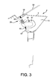
- the plate has a peripheral rim 65 which fits around an opening provided in a cross member 2 on which the plate is mounted ( Figure 3).
- This crossbar called crossbar under bay, is a structural element providing rigidity transverse to the vehicle, because of its fastenings to the lateral uprights.
- the crossbar under bay 2 also supports the windshield 32.
- a seal 50 is interposed between the plate 26 and the flange of the opening of the cross member 2 so as to ensure a tight connection.
- the crosspiece comprises reinforcing ribs, such as the ribs 10 provided with clearances 14 which provide a free space for receiving the mechanism 48 for supporting and driving the windscreen wiper blades.
- the plate 26 is mounted on the crossbar 2 by any suitable means for example by screws and bolts schematized by the dashed line 67 ( Figure 3). These screws pass through holes 69 provided in the wall of the plate (FIG. 2).
- the plate 26 thus makes it possible to seal the cross member and improves the vibratory and acoustic characteristics of this crossmember.
- the plate also reinforces the impact resistance of the crossbar 2.
- the fixing holes 69 by which the plate is placed in position against the cross member can also be used to hold it temporarily in position during a gluing step.
- the plate 26 has a slightly inclined shape from top to bottom towards the cross member 2 for architectural reasons, in particular the necessary space for the engine block.
- the plate 26 may be obtained by molding a plastic material preferably a composite material, or be formed of steel or aluminum by example.
- the selected material may or may not be identical to the material constituting the cross member 2.
- the plate 26 may be made of a thermosetting plastic material or a thermoplastic plastic material.
- a material envisaged for this part is AMC (heat-curable resin based on polyester reinforced with glass fibers).
- PA 66 GF30 thermoplastic resin based on polyamide based on 30% fiberglass.
- the plate can advantageously be produced by injection molding.
- the cross-member 2 rests on an upper deck cross member 17, which may be, for example, fixed on the deck 42.
- the deck 26 is disposed at one end of the deck.
- the cross member 2 which frees a space on the other side of the cross member for another element, for example an integrated water box 35 having a water discharge tube 22 connected to the deck 42 ( Figure 4).
- the water box can extend towards the side where the plate is located.
- the outer shape of the plate 26 can then be modified so that a correct arrangement is made between the water box and the plate.
Abstract
Description
La traverse inférieure de baie d'un véhicule automobile vise à assurer une tenue structurelle de la zone sous-baie, c'est-à-dire de la zone située sous l'extrémité avant du pare-brise. C'est également dans cette zone qu'est monté le mécanisme d'essuie-vitre, ainsi que les supports de bras d'essuie-vitre. Ces éléments prennent place, selon les architectures, dans la traverse inférieure de baie ou juste devant cette traverse.The lower berry beam of a motor vehicle aims to ensure a structural holding of the sub-bay area, that is to say, the area below the front end of the windshield. It is also in this area that the wiper mechanism is mounted, as well as the windscreen wiper arm supports. These elements take place, according to the architectures, in the lower cross of bay or just in front of this cross.
L'invention a pour objet une platine de support d'essuie-vitre de véhicule automobile qui permet de constituer avec la traverse un corps creux fermé de manière à en améliorer les caractéristiques vibratoires.The subject of the invention is a windscreen wiper support plate for a motor vehicle which makes it possible to form a closed hollow body with the crossmember so as to improve its vibration characteristics.
Ces buts sont atteints, conformément à l'invention, par le fait que la platine de support comporte une zone de fixation pour la fixation d'un mécanisme de support et d'entraînement des balais d'essuie-vitre et une zone d'assemblage pour fixer la platine sur un élément structurel du véhicule.These objects are achieved, in accordance with the invention, by the fact that the support plate includes a fixing zone for fixing a mechanism for supporting and driving the windscreen wiper blades and an assembly zone. to fix the plate on a structural element of the vehicle.
Avantageusement, la zone d'assemblage est une zone périphérique apte à obturer une ouverture prévue dans l'élément structurel du véhicule. La platine comporte au moins un trou de passage pour le passage d'au moins un axe de support et d'entraînement d'un balai d'essuie-vitre. L'élément structurel est avantageusement une traverse creuse, en particulier la traverse inférieure de baie.Advantageously, the assembly zone is a peripheral zone capable of closing off an opening provided in the structural element of the vehicle. The plate comprises at least one through hole for the passage of at least one support and drive axis of a windscreen wiper blade. The structural element is advantageously a hollow cross member, in particular the lower crossbeam.
L'invention concerne par ailleurs un procédé de montage d'un mécanisme de support et d'entraînement des balais d'essuie-vitre sur un élément structurel. Selon ce procédé :
- on pré-assemble le mécanisme de support et d'entraînement sur une platine conforme à l'invention de manière à constituer un sous-ensemble ;
- on monte ce sous-ensemble sur un élément structurel du véhicule.
- the support and drive mechanism is pre-assembled on a turntable according to the invention so as to form a subassembly;
- this subassembly is mounted on a structural element of the vehicle.
Grâce à ces étapes, la platine vient fermer l'ouverture de la traverse inférieure de baie qui est rendue nécessaire pour la mise en place du mécanisme d'essuie-vitre. Cette platine permet ainsi de rendre l'ensemble étanche et améliore les caractéristiques vibratoires et acoustiques de cet ensemble. De plus, l'ensemble fermé présente également une résistance accrue aux chocs.Thanks to these steps, the turntable closes the opening of the lower rack crossbar which is made necessary for the installation of the windscreen wiper mechanism. This plate thus makes the whole waterproof and improves the vibratory and acoustic characteristics of this set. In addition, the closed assembly also has increased impact resistance.
D'autres caractéristiques et avantages de l'invention apparaîtront encore à la lecture de la description qui suit d'un exemple de réalisation donné à titre illustratif en référence aux figures annexées. Sur ces figures :
- la figure 1 est une vue en perspective de l'intérieur d'une platine de support conforme à l'invention ;
- la figure 2 est une vue en perspective de la partie extérieure de la platine de la figure 1 ;
- la figure 3 est une vue partielle en coupe de la platine montée sur une structure de support ;
- la figure 4 est une vue en perspective de dessous d'une partie avant d'un châssis de véhicule automobile comportant la platine de l'invention.
- Figure 1 is a perspective view of the interior of a support plate according to the invention;
- Figure 2 is a perspective view of the outer portion of the plate of Figure 1;
- Figure 3 is a partial sectional view of the plate mounted on a support structure;
- Figure 4 is a perspective view from below of a front portion of a motor vehicle frame comprising the platen of the invention.
Sur la figure 1, on a représenté une vue en perspective d'une platine 26 à l'intérieur de laquelle est monté un mécanisme 48 de support et d'entraînement des balais d'essuie-vitre d'un véhicule automobile. Le mécanisme 48 est équipé d'un moteur électrique 50 qui entraîne une manivelle 52 par l'intermédiaire d'un réducteur 54. Par le jeu d'un mécanisme de type bielle et manivelle classique, la rotation de la manivelle 52 est transformée en une rotation angulaire alternative des axes de support 60 des balais d'essuie-glace. Dans l'exemple, les balais d'essuie-glace se déplacent parallèlement l'un à l'autre mais le concept de l'invention s'applique à toute autre forme de déplacement, par exemple antagoniste. De même, le mécanisme représenté comporte deux axes de supports, mais il va de soi que l'invention s'applique également à un mécanisme comportant un seul axe. Les axes 60 passent au travers d'ouvertures 62 prévues dans la platine 26. Ainsi, le mécanisme 48 peut être entièrement pré-assemblé sur la platine.In Figure 1, there is shown a perspective view of a
La platine comporte un rebord périphérique 65 qui s'adapte au pourtour d'une ouverture prévue dans une traverse 2 sur laquelle la platine est montée (figure 3). Cette traverse 2, appelée traverse sous baie, est un élément structurel assurant un rigidité transversale au véhicule, du fait de ses fixations aux montants latéraux. La traverse sous baie 2 permet également de supporter le pare-brise 32. Un joint d'étanchéité 50 est interposé entre la platine 26 et le rebord de l'ouverture de la traverse 2 de manière à assurer une jonction étanche. La traverse comporte des nervures de renfort, comme les nervures 10 pourvues de dégagements 14 qui ménagent un espace libre permettant de recevoir le mécanisme 48 de support et d'entraînement des balais d'essuie-glaces. La platine 26 est montée sur la traverse 2 par tout moyen approprié par exemple par des vis et des boulons schématisés par le trait tireté 67 (figure 3). Ces vis traversent des trous 69 prévus dans la paroi de la platine (figure 2) la platine 26 permet ainsi de rendre étanche la traverse et améliore les caractéristiques vibratoires et acoustiques de cette traverse. La platine renforce également la résistance au choc de la traverse 2.The plate has a
Les trous de fixation 69 par lesquels la platine est mise en position contre la traverse peuvent également être utilisés pour la maintenir provisoirement en position pendant une étape de collage.The
Avantageusement, la platine 26 présente une forme légèrement inclinée du haut vers le bas vers la traverse 2 pour des raisons d'architecture, en particulier la place nécessaire pour le bloc moteur.Advantageously, the
La platine 26 peut être obtenue par moulage d'un matériau plastique de préférence un matériau composite, ou être formé d'acier ou d'aluminium par exemple. Le matériau choisi peut être identique ou non au matériau constituant la traverse 2. A titre d'exemple non limitatif, la platine 26 peut être réalisée en un matériau plastique thermodurcissable ou en une matière plastique thermoplastique. A titre d'exemple particulier, un matériau envisagé pour cette pièce est l'AMC (résine thermo durcissable à base de polyester renforcée de fibres de verre). Un autre matériau particulier envisagé pour cette pièce est le PA 66 GF30 (résine thermoplastique à base polyamide renforcée de 30% de fibre de verre). La platine peut avantageusement être réalisée par moulage par injection.The
Comme on peut le constater sur les figures 3 et 4, la traverse 2 repose sur une traverse supérieure de tablier 17, qui peut être à titre d'exemple, fixée sur le tablier 42. Avantageusement, la platine 26 est disposée à une extrémité de la traverse 2, ce qui libère un espace de l'autre côté de la traverse pour un autre élément, par exemple une boîte à eau intégrée 35 comportant un tube d'évacuation d'eau 22 raccordé au tablier 42 (figure 4). A titre de variante non représentée, la boîte à eau peut s'étendre vers le côté où se situe la platine. La forme extérieure de la platine 26 peut être alors modifiée pour qu'un agencement correct soit réalisé entre la boîte à eau et la platine.As can be seen in FIGS. 3 and 4, the cross-member 2 rests on an upper
Claims (6)
Applications Claiming Priority (1)
| Application Number | Priority Date | Filing Date | Title |
|---|---|---|---|
| FR0451957A FR2874561B1 (en) | 2004-09-02 | 2004-09-02 | MOTOR VEHICLE WINDOW WIPER HOLDER PLATE AND METHOD FOR ASSEMBLING THE SAME |
Publications (1)
| Publication Number | Publication Date |
|---|---|
| EP1632412A1 true EP1632412A1 (en) | 2006-03-08 |
Family
ID=34948394
Family Applications (1)
| Application Number | Title | Priority Date | Filing Date |
|---|---|---|---|
| EP05300596A Ceased EP1632412A1 (en) | 2004-09-02 | 2005-07-18 | Support frame for a windscreen wiper of an automotive vehicle and associated mounting procedure |
Country Status (2)
| Country | Link |
|---|---|
| EP (1) | EP1632412A1 (en) |
| FR (1) | FR2874561B1 (en) |
Citations (5)
| Publication number | Priority date | Publication date | Assignee | Title |
|---|---|---|---|---|
| US4988144A (en) * | 1990-01-16 | 1991-01-29 | General Motors Corporation | Plenum and wiper module removable for engine service |
| EP0489630A1 (en) * | 1990-12-03 | 1992-06-10 | Valeo Systemes D'essuyage | Windscreen wiper support with integrated windscreen washer fluid container |
| US5203602A (en) * | 1991-01-17 | 1993-04-20 | Valeo Systemes D'essuyage | Base unit for a windshield wiper assembly |
| EP0574309A1 (en) * | 1992-06-12 | 1993-12-15 | Valeo Systemes D'essuyage | Wiper module, in particular for the windscreen of a motor vehicle |
| US20040084935A1 (en) * | 2002-10-31 | 2004-05-06 | Lyn Johnson | Plastic molded product for aligning and supporting a rotatable shaft and process for making same |
-
2004
- 2004-09-02 FR FR0451957A patent/FR2874561B1/en not_active Expired - Fee Related
-
2005
- 2005-07-18 EP EP05300596A patent/EP1632412A1/en not_active Ceased
Patent Citations (5)
| Publication number | Priority date | Publication date | Assignee | Title |
|---|---|---|---|---|
| US4988144A (en) * | 1990-01-16 | 1991-01-29 | General Motors Corporation | Plenum and wiper module removable for engine service |
| EP0489630A1 (en) * | 1990-12-03 | 1992-06-10 | Valeo Systemes D'essuyage | Windscreen wiper support with integrated windscreen washer fluid container |
| US5203602A (en) * | 1991-01-17 | 1993-04-20 | Valeo Systemes D'essuyage | Base unit for a windshield wiper assembly |
| EP0574309A1 (en) * | 1992-06-12 | 1993-12-15 | Valeo Systemes D'essuyage | Wiper module, in particular for the windscreen of a motor vehicle |
| US20040084935A1 (en) * | 2002-10-31 | 2004-05-06 | Lyn Johnson | Plastic molded product for aligning and supporting a rotatable shaft and process for making same |
Also Published As
| Publication number | Publication date |
|---|---|
| FR2874561A1 (en) | 2006-03-03 |
| FR2874561B1 (en) | 2008-03-14 |
Similar Documents
| Publication | Publication Date | Title |
|---|---|---|
| EP2512850B1 (en) | Motor vehicle trunk lid | |
| EP2300250B1 (en) | Opening, in particular tailgate for an automobile | |
| FR2619766A1 (en) | DOOR OF MOTOR VEHICLE | |
| FR2931783A1 (en) | ATTACHMENT AREA FOR COVER TRAINING IN A MOTOR VEHICLE | |
| EP2121362B8 (en) | Method for assembling a glazing on its holder by gluing, and means for realising said method | |
| WO2006027508A1 (en) | Cross member extending under the windshield aperture for a motor vehicle | |
| EP2900498A1 (en) | Inner structural finish for vehicle side door, and side door thus equipped | |
| EP1827881A1 (en) | Panoramic windscreen for a motor vehicle | |
| FR3060472A1 (en) | STRUCTURE OF A MOTOR VEHICLE WITH A SUNROOF, PAVILION FRAME AND CORNER PAVILION | |
| FR2855800A1 (en) | Optical unit receiving structure for use in motor vehicle, has journals for ensuring reference of window panel of optical unit and brackets fixing optical unit to structure in position resulting from reference of panel | |
| EP1632412A1 (en) | Support frame for a windscreen wiper of an automotive vehicle and associated mounting procedure | |
| FR3035035A1 (en) | DEVICE FOR REINFORCING A TAILGATE OF A MOTOR VEHICLE IN THERMOPLASTIC MATERIAL. | |
| EP1767438A1 (en) | A-pillar for the body of a motor vehicle | |
| FR2986768A1 (en) | Arrangement for arranging e.g. front feet lining, of body of car, has radiator tank comprising end elements designed to provide interior edge overlapping lower face of corresponding end of central element on overlapping zone at bottom | |
| FR2934538A1 (en) | Body shell for motor vehicle, has connection element fixed on wall of window post, and space with dimension permitting discharge of water present between wall of connection element and wall of window post | |
| EP1813512B1 (en) | Windscreen post and method of manufacturing said post | |
| FR2909352A1 (en) | Motor vehicle e.g. car, assembly, has cross beam of vehicle, which is structurally identical to cross beam of another vehicle, where latter vehicle has sheet roof panel with back ends that are supported on latter cross beam of vehicle | |
| EP1607292B1 (en) | Glazing and windscreen wiper assembly | |
| FR2970217A1 (en) | Device for sealing space between front wing of vehicle i.e. car and support structure of vehicle body, has deformable framework for allowing deformation of material block when block is in space between front wing and support structure | |
| FR2958216A1 (en) | Vehicle i.e. motor vehicle, has fixing unit co-operating with opening to integrate blade to structure, where opening extends in direction of thickness from blade, and blade is provided with insert and assembled inside opening | |
| EP3350003B1 (en) | Vehicle tailgate comprising a reinforced interface element | |
| WO2022129720A1 (en) | External opening control bracket of a vehicle | |
| EP1735207B1 (en) | Arrangement for fixing a mechanical reinforcing component for a motor vehicle to a side member | |
| FR3140579A1 (en) | Motor vehicle trunk flap hinge reinforcement | |
| FR3020600A1 (en) | ALLEGE DOOR HAVING A RIGIDIFICATION STRUCTURE |
Legal Events
| Date | Code | Title | Description |
|---|---|---|---|
| PUAI | Public reference made under article 153(3) epc to a published international application that has entered the european phase |
Free format text: ORIGINAL CODE: 0009012 |
|
| AK | Designated contracting states |
Kind code of ref document: A1 Designated state(s): AT BE BG CH CY CZ DE DK EE ES FI FR GB GR HU IE IS IT LI LT LU LV MC NL PL PT RO SE SI SK TR |
|
| AX | Request for extension of the european patent |
Extension state: AL BA HR MK YU |
|
| 17P | Request for examination filed |
Effective date: 20060901 |
|
| 17Q | First examination report despatched |
Effective date: 20061005 |
|
| AKX | Designation fees paid |
Designated state(s): AT BE BG CH CY CZ DE DK EE ES FI FR GB GR HU IE IS IT LI LT LU LV MC NL PL PT RO SE SI SK TR |
|
| STAA | Information on the status of an ep patent application or granted ep patent |
Free format text: STATUS: THE APPLICATION HAS BEEN REFUSED |
|
| 18R | Application refused |
Effective date: 20081027 |