EP1632124A1 - Schneidwerk für Erntemaschinen - Google Patents
Schneidwerk für Erntemaschinen Download PDFInfo
- Publication number
- EP1632124A1 EP1632124A1 EP05015950A EP05015950A EP1632124A1 EP 1632124 A1 EP1632124 A1 EP 1632124A1 EP 05015950 A EP05015950 A EP 05015950A EP 05015950 A EP05015950 A EP 05015950A EP 1632124 A1 EP1632124 A1 EP 1632124A1
- Authority
- EP
- European Patent Office
- Prior art keywords
- cutting
- side wall
- width
- cutter
- offset
- Prior art date
- Legal status (The legal status is an assumption and is not a legal conclusion. Google has not performed a legal analysis and makes no representation as to the accuracy of the status listed.)
- Granted
Links
Images

Classifications
-
- A—HUMAN NECESSITIES
- A01—AGRICULTURE; FORESTRY; ANIMAL HUSBANDRY; HUNTING; TRAPPING; FISHING
- A01D—HARVESTING; MOWING
- A01D41/00—Combines, i.e. harvesters or mowers combined with threshing devices
- A01D41/12—Details of combines
- A01D41/14—Mowing tables
Definitions
- the invention relates to a cutting unit for a self-propelled harvesting machine, preferably a combine harvester according to the preamble of claim 1.
- EP 0 789 990 discloses a combine harvester for a combine harvester in which the drive elements for the cutter bar sections, the reel and the auger are housed in a housing arranged externally on the side wall of the cutting table. In the front region of the side wall a Halmteiler is arranged on the cutting table.
- the housing has in a front region approximately the width of the Halmteilers, in the region of the Mähbalkenantriebs the width of the housing increases in a wedge shape and then extends in the rear region of the cutting table in the width reached parallel to the side wall.
- a disadvantage of this known cutting unit is that the arrangement of the cutter bar drives requires a wide design of the housing.
- the outside of the Halmteiler projecting part of the housing pushes the stock to the outside away, causing the plants are pressed to the ground or solve the unintentional moving of the stock Erntegutkörner of the plants and las lost so-called Rieselhold.
- the invention is therefore an object of the invention to provide a cutting unit, which avoids the disadvantages of the prior art and in which by a space-saving arrangement of the mower blade drive while maintaining the cutting width a narrow construction of the Halmteilers is possible, so that less crop by the Halmteiler in Towards the ground is pressed.
- the Halmteiler By the drive of the at least one cutting member is disposed above the cutting member and substantially within the working width of the cutting member, the Halmteiler can be made narrower.
- the Halmteiler can be made narrower while increasing the cutting width.
- the offset is designed as a Gutleitelement, so that the crop is deflected to the center of the cutting table and the sliding movement of Emteguts is supported in this direction.
- the side wall has a front side wall element and a rear side wall element, wherein the front side wall element, the cutting width and the rear side wall element limits a feed width and the offset constricting the side wall of the cutting width on the feed width, so that the Erntegutstrom through the Sidewall is merged.
- the cutting member is designed as a cutter bar and is arranged in the front region of the cutting table, wherein the offset is arranged in the region of the cutter bar, the mower blade drive can be accommodated in the immediate vicinity of the cutter bar and drive the mower bar section directly without further intermediate drive elements.
- the cutting table on a cutting trough and above the cutting trough an auger is arranged, wherein the offset is inclined in the direction of the auger, so that the cut from the cutterbar crop is gently merged and thereby falls in the direction of the cutting trough.
- the drive is arranged on the outside of the side wall in a casing and the casing has a first width in the region of the front side wall element and a second width in the region of the rear side wall element, wherein the second width is greater than the first Width is so that the enclosure is adapted to the size and arrangement of the drive on the one hand and builds on the other hand, at least in the area of the Halmteilers as narrow as possible.
- the envelope is closable with a cover which runs parallel to the direction of travel of the harvester and in the front region of the housing a Halmteilerspitze is arranged on the cutting table, which terminates approximately flush with the front side wall and the cover and thereby within the Extension lines of the front side wall element and the cover is located so that the casing together with the Halmteilerspitze results in a Halmteiler that deflects the crop only in the area of Halmteiler dictate.
- FIG. 1 partially shows the plan view of an agricultural harvester 2 designed as a self-propelled combine harvester 1, on whose inclined conveyor 3 a cutting unit 4 is arranged.
- the cutter 4 consists essentially of a cutting table 6 with a cutting trough 7, which is provided at both ends with a respective side wall 8. Above the cutting trough 7 is approximately flush between the side walls 8, a rotationally driven auger 10 is arranged. The crop is cut off by two arranged in the front region of the cutting unit 6, as oscillating driven cutterbar sections 12 cutting members 11 and then fed to the auger 10, which conveys the crop to the inclined conveyor 3. It is within the scope of the invention that the cutting unit 6 can be associated with only a single cutter bar section 12.
- a rotationally driven, height-adjustable reel 13 is arranged in front of the auger 10, with which the crop is deflected over the mower bar sections 12 in the direction of the cutting trough 7.
- the following description refers to one half of the symmetrically constructed cutting unit. 4
- the side wall 8 has an offset 14 designed as a material guide element, which connects a front side wall element 15 of the side wall 8 and a rear side wall element 16 of the side wall 8 offset laterally inwards. Both the front side wall element 15 and the rear side wall element 16 run parallel to the direction of travel of the combine harvester 1.
- the front side wall member 15 defines a working width 17 of the cutting unit 4, in which the crop is harvested from the field.
- the offset 14 runs from the front side wall member 15 obliquely inward to the rear side wall member 16, so that the working width 17 is constricted to a feed width 18, which is bounded by the rear side wall elements 16.
- the crop cut off from the cutter bar sections 12 is thus brought together by the offset 14 on the intake width 18.
- a casing 19 is arranged, which is closed with a cover 20, wherein the cover 20 is also parallel to the direction of travel of the combine 1.
- the drive 9 for the cutter bar section 12 is arranged.
- the casing 19 in the region of the front side wall 15 has a first width 21 and in the region of the rear side wall 15, a second width 22 which is greater than the first width 21, so that the drive 9 according to the invention substantially within the working width 17 of the cutting member 11 and as can be seen from Fig.2 above the cutting member 11 to save space in the immediate vicinity of the cutting member 11 can be arranged.
- a straw dividing tip 24 is arranged on the cutting table 6, which terminates approximately flush with the front side wall element 15 and the cover 20 and lies within the extension lines 25, 26 of the front side wall element 15 and the cover 20.
- the offset 14 is inclined in the direction of the auger 10 and extends over the entire side wall 8, wherein it has approximately a constant width 28.
- the front side wall element 15 is arranged predominantly in the area in front of the cutter bar section 12 and partially above the cutter bar section 12, while the rear side wall element 16 is arranged exclusively behind the cutter bar section 12.
Landscapes
- Life Sciences & Earth Sciences (AREA)
- Environmental Sciences (AREA)
- Outside Dividers And Delivering Mechanisms For Harvesters (AREA)
- Harvester Elements (AREA)
Abstract
Description
- Die Erfindungen betrifft ein Schneidwerk für eine selbstfahrende Erntemaschine, vorzugsweise einen Mähdrescher gemäß dem Oberbegriff des Anspruchs 1.
- In der EP 0 789 990 ist ein Schneidwerk für einen Mähdrescher offenbart, bei dem die Antriebselemente für die Mähbalkenabschnitte, die Haspel und die Einzugsschnecke in einem außen an der Seitenwand des Schneidtischs angeordneten Gehäuse untergebracht sind. Im vorderen Bereich der Seitenwand ist ein Halmteiler an dem Schneidtisch angeordnet. Das Gehäuse weist in einem vorderen Bereich annähernd die Breite des Halmteilers auf, im Bereich des Mähbalkenantriebs nimmt die Breite des Gehäuses keilförmig zu und verläuft anschließend im hinteren Bereich des Schneidtischs in der erreichten Breite parallel zur Seitenwand.
- Nachteilig bei diesem bekannten Schneidwerk ist, dass die Anordnung der Mähbalkenantriebe eine breite Gestaltung des Gehäuses erfordert. Der außen über den Halmteiler ragende Teil des Gehäuses drückt den Bestand nach außen weg, wodurch die Pflanzen zu boden gedrückt werden bzw. sich durch das unbeabsichtigte Bewegen des Bestandes Erntegutkörner von den Pflanzen lösen und las sogenannter Rieselverlust verloren gehen.
- Der Erfindung liegt daher die Aufgabe zugrunde, ein Schneidwerk zu schaffen, das die Nachteile des Standes der Technik vermeidet und bei dem durch eine bauraumsparende Anordnung des Mähmesserantriebs unter Beibehaltung der Schnittbreite eine schmale Bauweise des Halmteilers ermöglicht wird, so dass weniger Erntegut durch den Halmteiler in Richtung Boden gedrückt wird.
- Diese Aufgabe wird erfindungsgemäß durch die kennzeichnenden Merkmale des Anspruchs 1 gelöst. Weitere vorteilhafte Wirkungen des Erfindungsgegenstandes ergeben sich aus den Unteransprüchen.
- Indem die Arbeitsbreite des Schneidorgans im Wesentlichen der Breite des Schneidwerks entspricht, wird sichergestellt, dass das Schneidwerk nur geringe seitliche Ausladungen aufweist. Dies hat insbesondere den Vorteil, dass der das Schneidwerk umgebende Bestand weniger intensiv auf den Boden gedrückt wird, so dass sich die Rieselverluste erheblich reduzieren.
- Indem der Antrieb des wenigstens einen Schneidorgans oberhalb des Schneidorgans und im wesentlichen innerhalb der Arbeitsbreite des Schneidorgans angeordnet ist, kann der Halmteiler schmaler ausgeführt werden.
- Dadurch, dass das Schneidwerk einen Scheidtisch mit wenigstens zwei Seitenwänden aufweist, wobei zumindest die dem Schneidorgan zugeordnete Seitenwand einen Versatz aufweist, kann der Halmteiler bei gleichzeitiger Vergrößerung der Schnittbreite schmaler ausgeführt werden.
- Vorteilhafterweise ist der Versatz als Gutleitelement ausgebildet, so dass das Erntegut zur Mitte des Schneidtischs umgelenkt wird und die Gleitbewegung des Emteguts in diese Richtung unterstützt wird.
- In einer vorteilhaften Ausgestaltung der Erfindung weist die Seitenwand ein vorderes Seitenwandelement und ein hinteres Seitenwandelement auf, wobei das vordere Seitenwandelement die Schnittbreite und das hintere Seitenwandelement eine Einzugsbreite begrenzt und der Versatz die Seitenwand von der Schnittbreite auf die Einzugsbreite einschnürt, so dass der Erntegutstrom durch die Seitenwand zusammengeführt wird.
- Dadurch, dass das Schneidorgan als Mähbalkenabschnitt ausgeführt ist und im vorderen Bereich des Schneidtischs angeordnet ist, wobei der Versatz im Bereich des Mähbalkenabschnitts angeordnet ist, kann der Mähmesserantrieb in unmittelbarer Nähe des Mähbalkenabschnitts untergebracht werden und den Mähbalkenabschnitt direkt ohne weitere zwischengeschaltetete Antriebselemente antreiben.
- In einer vorteilhaften Ausgestaltung der Erfindung weist der Schneidtisch eine Schneidwerksmulde auf und oberhalb der Schneidwerksmulde ist eine Einzugsschnecke angeordnet, wobei der Versatz in Richtung der Einzugsschnecke geneigt ist, so dass das von Mähbalken abgeschnittene Erntegut schonend zusammengeführt wird und dabei in Richtung der Schneidwerksmulde fällt.
- In einer weiteren vorteilhaften Ausgestaltung der Erfindung ist der Antrieb an der Außenseite der Seitenwand in einer Umhäusung angeordnet und die Umhäusung weist im Bereich des vorderen Seitenwandelement eine erste Breite und im Bereich des hinteren Seitenwandelements eine zweite Breite auf, wobei die zweite Breite größer als die erste Breite ist, so dass die Umhäusung zum einen auf die Größe und Anordnung des Antriebs angepasst ist und zum anderen zumindest im Bereich des Halmteilers so schmal wie möglich baut.
- In einer vorteilhaften Weiterbildung der Erfindung ist die Umhäusung mit einer Abdeckung verschließbar, die parallel zur Fahrtrichtung der Erntemaschine verläuft und im frontseitigen Bereich der Umhäusung eine Halmteilerspitze an dem Schneidtisch angeordnet ist, die annähernd bündig mit dem vorderen Seitenwand und der Abdeckung abschließt und dabei innerhalb der Verlängerungslinien des vorderen Seitenwandelements und der Abdeckung liegt, so dass die Umhäusung zusammen mit der Halmteilerspitze einen Halmteiler ergibt, der das Erntegut nur im Bereich der Halmteilerspitze umlenkt.
- Es zeigen:
- Fig.1
- den vorderen Teil einer Draufsicht eines schematisch dargestellten Mähdreschers mit einem erfindungsgemäßen Schneidwerk,
- Fig.2
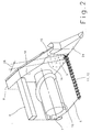
- eine perspektivische Ansicht eines erfindungsgemäßen Schneidwerks.
- In der Fig.1 ist teilweise die Draufsicht einer als selbstfahrender Mähdrescher 1 ausgeführten, landwirtschaftlichen Erntemaschine 2 dargestellt, an deren Schrägförderer 3 ein Schneidwerk 4 angeordnet ist. Das Schneidwerk 4 besteht im wesentlichen aus einem Schneidtisch 6 mit einer Schneidwerksmulde 7, der an beiden Enden jeweils mit einer Seitenwand 8 versehen ist. Oberhalb der Schneidwerksmulde 7 ist annähernd bündig zwischen den Seitenwänden 8 eine rotierend angetriebenen Einzugsschnecke 10 angeordnet. Das Erntegut wird von zwei im vorderen Bereich des Schneidwerks 6 angeordneten, als oszillierend angetriebene Mähbalkenabschnitte 12 ausgeführten Schneidorganen 11 abgeschnitten und anschließend der Einzugsschnecke 10 zugeführt, die das Erntegut zu dem Schrägförderer 3 befördert. Es liegt im Rahmen der Erfindung, dass dem Schneidwerk 6 auch nur ein einziger Mähbalkenabschnitt 12 zugeordnet sein kann. Oberhalb des Schneidtischs 6 ist vor der Einzugsschnecke 10 eine rotierend angetriebene, höhenverstellbare Haspel 13 angeordnet, mit der das Erntegut über die Mähbalkenabschnitte 12 in Richtung der Schneidwerksmulde 7 umgelenkt wird. Die nachfolgende Beschreibung bezieht sich auf eine Hälfte des symmetrisch aufgebauten Schneidwerks 4.
Die Seitenwand 8 weist im Bereich des Mähbalkenabschnitts 12 einen als Gutleitelement ausgebildeten Versatz 14 auf, der ein vorderes Seitenwandelement 15 der Seitenwand 8 und ein dazu seitlich nach innen versetztes hinteres Seitenwandelement 16 der Seitenwand 8 miteinander verbindet. Sowohl das vordere Seitenwandelement 15 als auch das hintere Seitenwandelement 16 verlaufen parallel zur Fahrtrichtung des Mähdreschers 1.
Das vordere Seitenwandelement 15 begrenzt eine Arbeitsbreite 17 des Schneidwerks 4, in der das Erntegut vom Feld geerntet wird. Der Versatz 14 verläuft von dem vorderen Seitenwandelement 15 schräg nach innen bis zu dem hinteren Seitenwandelement 16, so dass die Arbeitsbreite 17 auf eine Einzugbreite 18 eingeschnürt wird, welche von den hinteren Seitenwandelementen 16 begrenzt wird. Das von den Mähbalkenabschnitten 12 abgeschnittene Erntegut wird somit durch den Versatz 14 auf die Einzugsbreite 18 zusammengeführt.
An der Außenseite der Seitenwand 8 des Schneidtischs 6 ist eine Umhäusung 19 angeordnet, die mit einer Abdeckung 20 verschlossen ist auf, wobei die Abdeckung 20 ebenfalls parallel zu Fahrtrichtung des Mähdreschers 1 verläuft. Innerhalb der Umhäusung 19 ist unter anderem der Antrieb 9 für den Mähbalkenabschnitt 12 angeordnet. Durch den Versatz 14 weist die Umhäusung 19 im Bereich der vorderen Seitenwand 15 eine erste Breite 21 und im Bereich der hinteren Seitenwand 15 eine zweite Breite 22, die größer als die erste Breite 21 ist, so dass der Antrieb 9 erfindungsgemäß im wesentlichen innerhalb der Arbeitsbreite 17 des Schneidorgans 11 und wie aus Fig.2 ersichtlich oberhalb des Schneidorgans 11 platzsparend in unmittelbarer Nähe zum Schneidorgan 11 angeordnet werden kann. Im frontseitigen Bereich der Umhäusung 19 ist eine Halmteilerspitze 24 an dem Schneidtisch 6 angeordnet, die annähernd bündig mit dem vorderen Seitenwandelement 15 und der Abdeckung 20 abschließt und dabei innerhalb der Verlängerungslinien 25, 26 des vorderen Seitenwandelements 15 und der Abdeckung 20 liegt. - Fig.2 zeigt eine perspektivische Ansicht des erfindungsgemäßen Schneidwerks 4. Der Versatz 14 ist in Richtung der Einzugsschnecke 10 geneigt und erstreckt sich über die gesamte Seitenwand 8, wobei er annähernd eine konstante Breite 28 aufweist. Das vordere Seitenwandelement 15 ist überwiegend im Bereich vor dem Mähbalkenabschnitt 12 und teilweise oberhalb des Mähbalkenabschnitts 12 angeordnet, während das hintere Seitenwandelement 16 ausschließlich hinter dem Mähbalkenabschnitt 12 angeordnet ist.
- Es liegt im Rahmen des Könnens eines Fachmannes die beschriebenen Ausführungsbeispiele in nicht dargestellter Weise abzuwandeln oder in anderen Maschinensystemen einzusetzen, um die beschriebenen Effekte zu erzielen, ohne dabei den Rahmen der Erfindung zu verlassen.
-
- 1
- Mähdrescher
- 2
- Landwirtschaftliche Erntemaschine
- 3
- Schrägförderer
- 4
- Schneidwerk
- 6
- Schneidtisch
- 7
- Schneidwerksmulde
- 8
- Seitenwand
- 9
- Mähmesserantrieb
- 10
- Einzugsschnecke
- 11
- Schneidorgan
- 12
- Mähbalkenabschnitt
- 13
- Haspel
- 14
- Versatz
- 15
- vorderes Seitenwandelement
- 16
- hinteres Seitenwandelement
- 17
- Arbeitsbreite
- 18
- Einzugsbreite
- 19
- Umhäusung
- 20
- Abdeckung
- 21
- Erste Breite
- 22
- Zweite Breite
- 24
- Halmteiler
- 25
- Verlängerungslinie
- 26
- Verlängerungslinie
- 28
- Breite
Claims (9)
- Schneidwerk (4) für eine selbstfahrende Erntemaschine (2) mit wenigstens einem von einem Antrieb (9 ) angetriebenen Schneidorgan (11), wobei das Schneidorgan (12) das Erntegut in einer Arbeitsbreite (17) vom Feld schneidet,
dadurch gekennzeichnet,
dass die Arbeitsbreite (17) des Schneidorgans (11) im wesentlichen der Breite des Schneidwerks (4) entspricht. - Schneidwerk (4) nach Anspruch 1,
dass der Antrieb (9) des wenigstens einen Schneidorgans (11) oberhalb des Schneidorgans (11) und im wesentlichen innerhalb der Arbeitsbreite (17) des Schneidorgans (11) angeordnet ist. - Schneidwerk (4) nach wenigstens einem der vorhergehenden Ansprüche,
dadurch gekennzeichnet,
dass das Schneidwerk (4) einen Schneidtisch (6) mit wenigstens zwei Seitenwänden (8) aufweist und zumindest die dem Schneidorgan (6) zugeordnete Seitenwand (8) einen Versatz (14) aufweist. - Schneidwerk (4) nach wenigstens einem der vorhergehenden Ansprüche,
dadurch gekennzeichnet,
dass der Versatz (14) als Gutleitelement ausgebildet ist. - Schneidwerk (4) nach wenigstens einem der vorhergehenden Ansprüche,
dadurch gekennzeichnet,
dass die Seitenwand (8) ein vorderes Seitenwandelement (15) und ein hinteres Seitenwandelement (16) aufweist, wobei das vordere Seitenwandelement (15) die Arbeitsbreite (17) des Schneidorgans (12) und das hintere Seitenwandelement (16) eine Einzugsbreite (18) des Schneidtischs (6) begrenzt und der Versatz (14) die Seitenwand (8) von der Arbeitsbreite (17) auf die Einzugsbreite (18) einschnürt. - Schneidwerk (4) nach wenigstens einem der vorhergehenden Ansprüche,
dadurch gekennzeichnet,
dass das Schneidorgan (12) als Mähbalkenabschnitt (11) ausgeführt ist und im vorderen Bereich des Schneidtischs (6) angeordnet ist, wobei der Versatz (14) im Bereich des Mähbalkenabschnitts (11) angeordnet ist. - Schneidwerk (4) nach wenigstens einem der vorhergehenden Ansprüche,
dadurch gekennzeichnet,
dass der Schneidtisch (6) eine Schneidwerksmulde (7) aufweist und oberhalb der Schneidwerksmulde (7) eine Einzugsschnecke (10) angeordnet ist, wobei der Versatz (14) in Richtung der Einzugsschnecke (10) geneigt ist. - Schneidwerk (4) nach wenigstens einem der vorhergehenden Ansprüche,
dadurch gekennzeichnet,
dass der Antrieb (9) an der Außenseite der Seitenwand (8) in einer Umhäusung (19) angeordnet ist und die Umhäusung (19) durch den Versatz (14) im Bereich des vorderen Seitenwandelements (15) eine erste Breite (21) und zumindest im Bereich des hinteren Seitenwandelementes (16) eine zweite Breite (22) aufweist, wobei die zweite Breite (22) größer als die erste Breite (21) ist. - Schneidwerk (4) nach wenigstens einem der vorhergehenden Ansprüche,
dadurch gekennzeichnet,
dass die Umhäusung (19) mit einer Abdeckung (20) verschließbar ist, die parallel zur Fahrtrichtung der Erntemaschine verläuft und im frontseitigen Bereich der Umhäusung eine Halmteilerspitze (23) an dem Schneidtisch (6) angeordnet ist, die annähernd bündig mit dem vorderen. Seitenwandelement (15) und der Abdeckung (20) abschließt und innerhalb der Verlängerungslinien (25, 26) des vorderen Seitenwandelements (15) und der Abdeckung (20) liegt.
Applications Claiming Priority (1)
| Application Number | Priority Date | Filing Date | Title |
|---|---|---|---|
| DE102004043613A DE102004043613A1 (de) | 2004-09-07 | 2004-09-07 | Schneidwerk für Erntemaschine |
Publications (2)
| Publication Number | Publication Date |
|---|---|
| EP1632124A1 true EP1632124A1 (de) | 2006-03-08 |
| EP1632124B1 EP1632124B1 (de) | 2012-11-14 |
Family
ID=35427812
Family Applications (1)
| Application Number | Title | Priority Date | Filing Date |
|---|---|---|---|
| EP05015950A Expired - Lifetime EP1632124B1 (de) | 2004-09-07 | 2005-07-22 | Schneidwerk für Erntemaschinen |
Country Status (4)
| Country | Link |
|---|---|
| US (1) | US20060075734A1 (de) |
| EP (1) | EP1632124B1 (de) |
| BR (1) | BRPI0503788A (de) |
| DE (1) | DE102004043613A1 (de) |
Families Citing this family (1)
| Publication number | Priority date | Publication date | Assignee | Title |
|---|---|---|---|---|
| DE102019127509A1 (de) * | 2019-10-11 | 2021-04-15 | Carl Geringhoff Gmbh & Co. Kg | Schneidwerk mit beweglichen Seitenwänden |
Citations (6)
| Publication number | Priority date | Publication date | Assignee | Title |
|---|---|---|---|---|
| GB2103063A (en) * | 1981-07-31 | 1983-02-16 | Fortschritt Veb K | Harvester |
| DE3534763A1 (de) * | 1984-10-31 | 1986-05-07 | Veb Kombinat Fortschritt Landmaschinen Neustadt In Sachsen, Ddr 8355 Neustadt | Maehmesserantrieb fuer halmfuttererntemaschinen |
| DE3512619A1 (de) * | 1985-04-06 | 1986-10-09 | Claas Ohg, 4834 Harsewinkel | Schneidwerksmulde fuer einen selbstfahrenden maehdrescher |
| US4910946A (en) * | 1988-06-20 | 1990-03-27 | Probe Adventures, Inc. | Extensible combine header |
| EP0789990A1 (de) | 1996-02-16 | 1997-08-20 | Capello F.Lli Renato E Francesco S.N.C. | Mähbrett für Getreide-Mähdrescher |
| WO1998053660A1 (en) * | 1997-05-29 | 1998-12-03 | Case Corporation | Combine header for both corn and grain |
Family Cites Families (7)
| Publication number | Priority date | Publication date | Assignee | Title |
|---|---|---|---|---|
| US2679719A (en) * | 1951-02-01 | 1954-06-01 | New Holland Machine Division O | Divider for harvester pickups |
| US3885377A (en) * | 1974-03-08 | 1975-05-27 | Nor Lo Engineering Co | Crop divider for harvester |
| US4199927A (en) * | 1978-04-12 | 1980-04-29 | Craig John R | Combine reel weed shield |
| US4296593A (en) * | 1980-06-09 | 1981-10-27 | Sperry - New Holland | Universal crop divider mechanism |
| US4330983A (en) * | 1980-12-01 | 1982-05-25 | J. E. Love Company | Floating divider for a harvester |
| US4550555A (en) * | 1984-08-02 | 1985-11-05 | Rohlik John W | Crop guiding attachment for a combine divider |
| US4965991A (en) * | 1989-11-09 | 1990-10-30 | Sauder David E | Crop feeding system |
-
2004
- 2004-09-07 DE DE102004043613A patent/DE102004043613A1/de not_active Withdrawn
-
2005
- 2005-07-22 EP EP05015950A patent/EP1632124B1/de not_active Expired - Lifetime
- 2005-09-02 BR BRPI0503788-3A patent/BRPI0503788A/pt not_active Application Discontinuation
- 2005-09-06 US US11/220,103 patent/US20060075734A1/en not_active Abandoned
Patent Citations (6)
| Publication number | Priority date | Publication date | Assignee | Title |
|---|---|---|---|---|
| GB2103063A (en) * | 1981-07-31 | 1983-02-16 | Fortschritt Veb K | Harvester |
| DE3534763A1 (de) * | 1984-10-31 | 1986-05-07 | Veb Kombinat Fortschritt Landmaschinen Neustadt In Sachsen, Ddr 8355 Neustadt | Maehmesserantrieb fuer halmfuttererntemaschinen |
| DE3512619A1 (de) * | 1985-04-06 | 1986-10-09 | Claas Ohg, 4834 Harsewinkel | Schneidwerksmulde fuer einen selbstfahrenden maehdrescher |
| US4910946A (en) * | 1988-06-20 | 1990-03-27 | Probe Adventures, Inc. | Extensible combine header |
| EP0789990A1 (de) | 1996-02-16 | 1997-08-20 | Capello F.Lli Renato E Francesco S.N.C. | Mähbrett für Getreide-Mähdrescher |
| WO1998053660A1 (en) * | 1997-05-29 | 1998-12-03 | Case Corporation | Combine header for both corn and grain |
Also Published As
| Publication number | Publication date |
|---|---|
| US20060075734A1 (en) | 2006-04-13 |
| BRPI0503788A (pt) | 2006-04-18 |
| DE102004043613A1 (de) | 2006-03-23 |
| EP1632124B1 (de) | 2012-11-14 |
Similar Documents
| Publication | Publication Date | Title |
|---|---|---|
| DE2628414C2 (de) | ||
| DE1482896C3 (de) | Mähdreschermähwerk | |
| EP0824856B1 (de) | Maschine zum reihenunabhängigen Mähen und Häckseln von Mais und dgl. stengelartigem Erntegut | |
| EP3791709B1 (de) | Messerklinge für eine schneidvorrichtung | |
| EP0891693B1 (de) | Mähscheibe und Mähwerk | |
| EP1010363B1 (de) | Maschine zum Mähen und Häckseln von Mais und dgl. stengelartigem Erntegut | |
| DE3874305T2 (de) | Maehwerk mit versteiftem maehbalken. | |
| DE2700093A1 (de) | Maehdrescher der axialflussbauart | |
| DE1507195B2 (de) | Erntemaschine für stengeliges Halmgut, insbesondere Mais | |
| EP0503468B1 (de) | Schneidwerk für Mähdrescher | |
| EP1247440B1 (de) | Erntemaschine für stengelartiges Erntegut | |
| DE3726967C2 (de) | Erntegerät zum Ernten von Mais oder anderen Körnerfrüchten | |
| DE2735784A1 (de) | Reihen-schneidvorsatz fuer feldhaecksler | |
| DE10323829A1 (de) | Hochschnitteinrichtung für Mähdrescher | |
| DE1189777B (de) | Schlegelmaehhaecksler | |
| EP2923556B1 (de) | Vorsatzgerät für einen selbstfahrenden Mähdrescher zum Ernten von Mais | |
| EP2430900B1 (de) | Vorsatzgerät | |
| EP1632124B1 (de) | Schneidwerk für Erntemaschinen | |
| EP3797577B1 (de) | Mähdrescher mit restkornsensor | |
| DE2412461A1 (de) | Feldhaecksler | |
| DE3024663A1 (de) | Feldhaecksler | |
| DE1263386B (de) | Rundschlagmaeher | |
| DE2830164A1 (de) | Axial-, dresch- und trennvorrichtung fuer maehdrescher | |
| DE2610600A1 (de) | Maehdrescher der axialfluss-bauart | |
| DE19607350A1 (de) | Mäh- und/oder Vertikutiermaschine |
Legal Events
| Date | Code | Title | Description |
|---|---|---|---|
| PUAI | Public reference made under article 153(3) epc to a published international application that has entered the european phase |
Free format text: ORIGINAL CODE: 0009012 |
|
| AK | Designated contracting states |
Kind code of ref document: A1 Designated state(s): AT BE BG CH CY CZ DE DK EE ES FI FR GB GR HU IE IS IT LI LT LU LV MC NL PL PT RO SE SI SK TR |
|
| AX | Request for extension of the european patent |
Extension state: AL BA HR MK YU |
|
| 17P | Request for examination filed |
Effective date: 20060908 |
|
| AKX | Designation fees paid |
Designated state(s): AT BE BG CH CY CZ DE DK EE ES FI FR GB GR HU IE IS IT LI LT LU LV MC NL PL PT RO SE SI SK TR |
|
| 17Q | First examination report despatched |
Effective date: 20061102 |
|
| GRAP | Despatch of communication of intention to grant a patent |
Free format text: ORIGINAL CODE: EPIDOSNIGR1 |
|
| GRAS | Grant fee paid |
Free format text: ORIGINAL CODE: EPIDOSNIGR3 |
|
| GRAA | (expected) grant |
Free format text: ORIGINAL CODE: 0009210 |
|
| AK | Designated contracting states |
Kind code of ref document: B1 Designated state(s): AT BE BG CH CY CZ DE DK EE ES FI FR GB GR HU IE IS IT LI LT LU LV MC NL PL PT RO SE SI SK TR |
|
| REG | Reference to a national code |
Ref country code: GB Ref legal event code: FG4D Free format text: NOT ENGLISH |
|
| REG | Reference to a national code |
Ref country code: AT Ref legal event code: REF Ref document number: 583456 Country of ref document: AT Kind code of ref document: T Effective date: 20121115 Ref country code: CH Ref legal event code: EP |
|
| REG | Reference to a national code |
Ref country code: IE Ref legal event code: FG4D Free format text: LANGUAGE OF EP DOCUMENT: GERMAN |
|
| REG | Reference to a national code |
Ref country code: DE Ref legal event code: R096 Ref document number: 502005013247 Country of ref document: DE Effective date: 20130110 |
|
| REG | Reference to a national code |
Ref country code: NL Ref legal event code: VDEP Effective date: 20121114 |
|
| REG | Reference to a national code |
Ref country code: LT Ref legal event code: MG4D |
|
| PG25 | Lapsed in a contracting state [announced via postgrant information from national office to epo] |
Ref country code: FI Free format text: LAPSE BECAUSE OF FAILURE TO SUBMIT A TRANSLATION OF THE DESCRIPTION OR TO PAY THE FEE WITHIN THE PRESCRIBED TIME-LIMIT Effective date: 20121114 Ref country code: LT Free format text: LAPSE BECAUSE OF FAILURE TO SUBMIT A TRANSLATION OF THE DESCRIPTION OR TO PAY THE FEE WITHIN THE PRESCRIBED TIME-LIMIT Effective date: 20121114 Ref country code: ES Free format text: LAPSE BECAUSE OF FAILURE TO SUBMIT A TRANSLATION OF THE DESCRIPTION OR TO PAY THE FEE WITHIN THE PRESCRIBED TIME-LIMIT Effective date: 20130225 Ref country code: SE Free format text: LAPSE BECAUSE OF FAILURE TO SUBMIT A TRANSLATION OF THE DESCRIPTION OR TO PAY THE FEE WITHIN THE PRESCRIBED TIME-LIMIT Effective date: 20121114 |
|
| PG25 | Lapsed in a contracting state [announced via postgrant information from national office to epo] |
Ref country code: GR Free format text: LAPSE BECAUSE OF FAILURE TO SUBMIT A TRANSLATION OF THE DESCRIPTION OR TO PAY THE FEE WITHIN THE PRESCRIBED TIME-LIMIT Effective date: 20130215 Ref country code: PL Free format text: LAPSE BECAUSE OF FAILURE TO SUBMIT A TRANSLATION OF THE DESCRIPTION OR TO PAY THE FEE WITHIN THE PRESCRIBED TIME-LIMIT Effective date: 20121114 Ref country code: SI Free format text: LAPSE BECAUSE OF FAILURE TO SUBMIT A TRANSLATION OF THE DESCRIPTION OR TO PAY THE FEE WITHIN THE PRESCRIBED TIME-LIMIT Effective date: 20121114 Ref country code: PT Free format text: LAPSE BECAUSE OF FAILURE TO SUBMIT A TRANSLATION OF THE DESCRIPTION OR TO PAY THE FEE WITHIN THE PRESCRIBED TIME-LIMIT Effective date: 20130314 Ref country code: CY Free format text: LAPSE BECAUSE OF FAILURE TO SUBMIT A TRANSLATION OF THE DESCRIPTION OR TO PAY THE FEE WITHIN THE PRESCRIBED TIME-LIMIT Effective date: 20121114 Ref country code: LV Free format text: LAPSE BECAUSE OF FAILURE TO SUBMIT A TRANSLATION OF THE DESCRIPTION OR TO PAY THE FEE WITHIN THE PRESCRIBED TIME-LIMIT Effective date: 20121114 |
|
| PG25 | Lapsed in a contracting state [announced via postgrant information from national office to epo] |
Ref country code: EE Free format text: LAPSE BECAUSE OF FAILURE TO SUBMIT A TRANSLATION OF THE DESCRIPTION OR TO PAY THE FEE WITHIN THE PRESCRIBED TIME-LIMIT Effective date: 20121114 Ref country code: BG Free format text: LAPSE BECAUSE OF FAILURE TO SUBMIT A TRANSLATION OF THE DESCRIPTION OR TO PAY THE FEE WITHIN THE PRESCRIBED TIME-LIMIT Effective date: 20130214 Ref country code: SK Free format text: LAPSE BECAUSE OF FAILURE TO SUBMIT A TRANSLATION OF THE DESCRIPTION OR TO PAY THE FEE WITHIN THE PRESCRIBED TIME-LIMIT Effective date: 20121114 Ref country code: CZ Free format text: LAPSE BECAUSE OF FAILURE TO SUBMIT A TRANSLATION OF THE DESCRIPTION OR TO PAY THE FEE WITHIN THE PRESCRIBED TIME-LIMIT Effective date: 20121114 Ref country code: DK Free format text: LAPSE BECAUSE OF FAILURE TO SUBMIT A TRANSLATION OF THE DESCRIPTION OR TO PAY THE FEE WITHIN THE PRESCRIBED TIME-LIMIT Effective date: 20121114 |
|
| PG25 | Lapsed in a contracting state [announced via postgrant information from national office to epo] |
Ref country code: NL Free format text: LAPSE BECAUSE OF FAILURE TO SUBMIT A TRANSLATION OF THE DESCRIPTION OR TO PAY THE FEE WITHIN THE PRESCRIBED TIME-LIMIT Effective date: 20121114 Ref country code: IT Free format text: LAPSE BECAUSE OF FAILURE TO SUBMIT A TRANSLATION OF THE DESCRIPTION OR TO PAY THE FEE WITHIN THE PRESCRIBED TIME-LIMIT Effective date: 20121114 Ref country code: RO Free format text: LAPSE BECAUSE OF FAILURE TO SUBMIT A TRANSLATION OF THE DESCRIPTION OR TO PAY THE FEE WITHIN THE PRESCRIBED TIME-LIMIT Effective date: 20121114 |
|
| PLBE | No opposition filed within time limit |
Free format text: ORIGINAL CODE: 0009261 |
|
| STAA | Information on the status of an ep patent application or granted ep patent |
Free format text: STATUS: NO OPPOSITION FILED WITHIN TIME LIMIT |
|
| 26N | No opposition filed |
Effective date: 20130815 |
|
| REG | Reference to a national code |
Ref country code: DE Ref legal event code: R097 Ref document number: 502005013247 Country of ref document: DE Effective date: 20130815 |
|
| PG25 | Lapsed in a contracting state [announced via postgrant information from national office to epo] |
Ref country code: MC Free format text: LAPSE BECAUSE OF FAILURE TO SUBMIT A TRANSLATION OF THE DESCRIPTION OR TO PAY THE FEE WITHIN THE PRESCRIBED TIME-LIMIT Effective date: 20121114 |
|
| REG | Reference to a national code |
Ref country code: CH Ref legal event code: PL |
|
| GBPC | Gb: european patent ceased through non-payment of renewal fee |
Effective date: 20130722 |
|
| REG | Reference to a national code |
Ref country code: IE Ref legal event code: MM4A |
|
| PG25 | Lapsed in a contracting state [announced via postgrant information from national office to epo] |
Ref country code: LI Free format text: LAPSE BECAUSE OF NON-PAYMENT OF DUE FEES Effective date: 20130731 Ref country code: GB Free format text: LAPSE BECAUSE OF NON-PAYMENT OF DUE FEES Effective date: 20130722 Ref country code: CH Free format text: LAPSE BECAUSE OF NON-PAYMENT OF DUE FEES Effective date: 20130731 |
|
| PG25 | Lapsed in a contracting state [announced via postgrant information from national office to epo] |
Ref country code: IE Free format text: LAPSE BECAUSE OF NON-PAYMENT OF DUE FEES Effective date: 20130722 |
|
| REG | Reference to a national code |
Ref country code: AT Ref legal event code: MM01 Ref document number: 583456 Country of ref document: AT Kind code of ref document: T Effective date: 20130722 |
|
| PG25 | Lapsed in a contracting state [announced via postgrant information from national office to epo] |
Ref country code: AT Free format text: LAPSE BECAUSE OF NON-PAYMENT OF DUE FEES Effective date: 20130722 |
|
| PG25 | Lapsed in a contracting state [announced via postgrant information from national office to epo] |
Ref country code: TR Free format text: LAPSE BECAUSE OF FAILURE TO SUBMIT A TRANSLATION OF THE DESCRIPTION OR TO PAY THE FEE WITHIN THE PRESCRIBED TIME-LIMIT Effective date: 20121114 |
|
| PG25 | Lapsed in a contracting state [announced via postgrant information from national office to epo] |
Ref country code: LU Free format text: LAPSE BECAUSE OF NON-PAYMENT OF DUE FEES Effective date: 20130722 Ref country code: HU Free format text: LAPSE BECAUSE OF FAILURE TO SUBMIT A TRANSLATION OF THE DESCRIPTION OR TO PAY THE FEE WITHIN THE PRESCRIBED TIME-LIMIT; INVALID AB INITIO Effective date: 20050722 |
|
| PG25 | Lapsed in a contracting state [announced via postgrant information from national office to epo] |
Ref country code: IS Free format text: LAPSE BECAUSE OF FAILURE TO SUBMIT A TRANSLATION OF THE DESCRIPTION OR TO PAY THE FEE WITHIN THE PRESCRIBED TIME-LIMIT Effective date: 20121114 |
|
| REG | Reference to a national code |
Ref country code: FR Ref legal event code: PLFP Year of fee payment: 12 |
|
| REG | Reference to a national code |
Ref country code: FR Ref legal event code: PLFP Year of fee payment: 13 |
|
| REG | Reference to a national code |
Ref country code: FR Ref legal event code: PLFP Year of fee payment: 14 |
|
| PGFP | Annual fee paid to national office [announced via postgrant information from national office to epo] |
Ref country code: FR Payment date: 20180725 Year of fee payment: 14 |
|
| PG25 | Lapsed in a contracting state [announced via postgrant information from national office to epo] |
Ref country code: FR Free format text: LAPSE BECAUSE OF NON-PAYMENT OF DUE FEES Effective date: 20190731 |
|
| P01 | Opt-out of the competence of the unified patent court (upc) registered |
Effective date: 20230512 |
|
| PGFP | Annual fee paid to national office [announced via postgrant information from national office to epo] |
Ref country code: DE Payment date: 20230719 Year of fee payment: 19 Ref country code: BE Payment date: 20230719 Year of fee payment: 19 |
|
| REG | Reference to a national code |
Ref country code: DE Ref legal event code: R119 Ref document number: 502005013247 Country of ref document: DE |
|
| PG25 | Lapsed in a contracting state [announced via postgrant information from national office to epo] |
Ref country code: DE Free format text: LAPSE BECAUSE OF NON-PAYMENT OF DUE FEES Effective date: 20250201 |
|
| PG25 | Lapsed in a contracting state [announced via postgrant information from national office to epo] |
Ref country code: BE Free format text: LAPSE BECAUSE OF NON-PAYMENT OF DUE FEES Effective date: 20240731 |
|
| REG | Reference to a national code |
Ref country code: BE Ref legal event code: MM Effective date: 20240731 |