EP1631808B1 - Capteur acoustique - Google Patents
Capteur acoustique Download PDFInfo
- Publication number
- EP1631808B1 EP1631808B1 EP04735233A EP04735233A EP1631808B1 EP 1631808 B1 EP1631808 B1 EP 1631808B1 EP 04735233 A EP04735233 A EP 04735233A EP 04735233 A EP04735233 A EP 04735233A EP 1631808 B1 EP1631808 B1 EP 1631808B1
- Authority
- EP
- European Patent Office
- Prior art keywords
- signal
- measurement signal
- measuring element
- frequency range
- electrical measurement
- Prior art date
- Legal status (The legal status is an assumption and is not a legal conclusion. Google has not performed a legal analysis and makes no representation as to the accuracy of the status listed.)
- Expired - Lifetime
Links
- 238000005259 measurement Methods 0.000 claims description 17
- 230000005540 biological transmission Effects 0.000 claims description 8
- 238000003745 diagnosis Methods 0.000 claims description 7
- 230000001143 conditioned effect Effects 0.000 claims description 2
- 238000009499 grossing Methods 0.000 claims description 2
- 238000011156 evaluation Methods 0.000 description 14
- 230000003750 conditioning effect Effects 0.000 description 5
- 230000005236 sound signal Effects 0.000 description 5
- 230000003595 spectral effect Effects 0.000 description 4
- 230000008054 signal transmission Effects 0.000 description 3
- 239000011248 coating agent Substances 0.000 description 2
- 238000000576 coating method Methods 0.000 description 2
- 238000009795 derivation Methods 0.000 description 2
- 238000001514 detection method Methods 0.000 description 2
- 239000002184 metal Substances 0.000 description 2
- 238000000034 method Methods 0.000 description 2
- 230000008878 coupling Effects 0.000 description 1
- 238000010168 coupling process Methods 0.000 description 1
- 238000005859 coupling reaction Methods 0.000 description 1
- 230000002950 deficient Effects 0.000 description 1
- 238000010586 diagram Methods 0.000 description 1
- 238000005516 engineering process Methods 0.000 description 1
- 230000001788 irregular Effects 0.000 description 1
- 239000000463 material Substances 0.000 description 1
- 230000010355 oscillation Effects 0.000 description 1
Images
Classifications
-
- G—PHYSICS
- G01—MEASURING; TESTING
- G01M—TESTING STATIC OR DYNAMIC BALANCE OF MACHINES OR STRUCTURES; TESTING OF STRUCTURES OR APPARATUS, NOT OTHERWISE PROVIDED FOR
- G01M3/00—Investigating fluid-tightness of structures
- G01M3/02—Investigating fluid-tightness of structures by using fluid or vacuum
- G01M3/04—Investigating fluid-tightness of structures by using fluid or vacuum by detecting the presence of fluid at the leakage point
- G01M3/24—Investigating fluid-tightness of structures by using fluid or vacuum by detecting the presence of fluid at the leakage point using infrasonic, sonic, or ultrasonic vibrations
Definitions
- the invention relates to a sound pickup, in particular an ultrasonic pickup for the acoustic diagnosis of machines, according to the preamble of claim 1.
- valve or bearing damage should be detected as early as possible, that is, before a failure of the components can cause a shutdown of the system.
- defective valve seats lead to leakage currents that produce a broadband ultrasonic emission.
- a recording and evaluation of the ultrasonic emissions of a valve can thus serve for the early detection of valve damage.
- a suitable for recording the structure-borne sound signal ultrasonic transducer is known from DE 299 12 847 U1. It has a housing in which a piezoelectric measuring element and a circuit for signal processing are arranged.
- the conditioned measurement signal can be fed as output signal via a cable to a remotely located evaluation device.
- the auxiliary power required to operate the signal conditioning circuit is supplied by the evaluation device and also made available to the sound pickup via the cable. In the evaluation so an additional means for generating the auxiliary power and in the cable additional wires for auxiliary power transmission are required.
- a sensor with wireless signal transmission which has inside a housing a piezoelectric measuring element for generating an electrical measuring signal and an electronic circuit.
- the auxiliary energy required for operating the electronic circuit and for signal transmission is obtained from the electrical measurement signal.
- the invention has for its object to provide a sound pickup, in particular an ultrasonic transducer for the acoustic diagnosis of machines, which manages without an external auxiliary power supply and makes it possible to transmit a measurement signal in a frequency range to be evaluated.
- the invention has the advantage that the sound pickup removes the energy required for operating an electronic circuit for signal conditioning in its surroundings, so that it does not have to be supplied to it via separate wires of a cable. Since the sound pickup generates the auxiliary power from the sound signal to be recorded, there is always sufficient energy at the times for the operation of the circuit to which there is a sound signal exceeding a certain minimum intensity and a corresponding output signal is to be generated.
- the transmission of the output signal to the evaluation device can, for example, be asymmetric or symmetrical via cable or, alternatively, wirelessly via radio or infrared light.
- the auxiliary energy is generated from the electrical measurement signal of the piezoelectric measuring element. This has the advantage that in addition to the actual measuring element of the sound pickup no additional electroacoustic components are required.
- a spectral range of the measurement signal above a frequency of 50 kHz is evaluated, but does not have to start immediately at 50 kHz. Only signal components in this frequency range must be amplified and transmitted to the evaluation device wired or wireless.
- the signal delivered by the piezoelectric measuring element is particularly energy rich in the frequency range between 0 and 50 kHz, since the signal components here have a considerably greater amplitude.
- the signal components located in this region can be advantageously used to generate the energy required to operate the conditioning circuit.
- a crossover by which the electrical measurement signal of the piezoelectric element substantially in an evaluation signal in a first frequency range, which is processed in a suitable for transmission to an evaluation device arranged outside the housing, and a supply signal in one second frequency range is supplied, which provides the required auxiliary power for the operation of the conditioning circuit.
- Such a crossover also has the advantage that a slight distortion of the evaluation signal takes place despite the derivative of the supply signal from the same electrical measurement signal.
- a better quality of the auxiliary power for the circuit for signal processing and thus a better quality of the output signal is achieved when a Device for rectification and for smoothing the supply signal is provided.
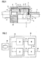
- FIG. 1 In the lower half of FIG. 1, that is to say below an axis 1, a side view of a substantially rotationally symmetrical sound pickup is shown, in the upper half a longitudinal section through the sound pickup.
- the acoustic pickup has according to Figure 1, a cup-shaped housing 2, which is provided on its outer side with engagement surfaces 3 for a wrench.
- a threaded pin 4 is provided, which can be screwed into a corresponding threaded hole on the cultivation site. With a wrench, the required torque can be applied to ensure a good coupling of the vibrations via a pressure surface 5 of the housing bottom at the cultivation site.
- the sleeve portion 8 together with a sleeve portion 9 and a plate spring 10, a sleeve which extends over the entire length of the measuring electronics of the sound pickup and essential part of the electromagnetic shielding is.
- Within the sleeve are further connecting leads 11 and 12 for electrically connecting a signal electrode 13 and a ground electrode 14 of the piezoelectric measuring element 7 with an electronic circuit 15, the electronic circuit 15 itself and electrical leads 16 to the electronic circuit shielded against electromagnetic interference.
- the electronic circuit 15 serves to convert the charge shifts caused by acoustic oscillations in the piezoelectric measuring element 7 into a signal which can be transmitted well via a cable or-alternatively to the exemplary embodiment shown-also wirelessly over greater distances.
- a base of the sleeve is closed by the electrically conductive metal coating of the insulating 6.
- the metal coating simultaneously serves as a ground electrode 14.
- the inner wall of the sleeve is provided with an internal thread into which a BNC socket 17 is screwed in until a circumferential collar 18 of the BNC socket 17 to lie on a seal 19 comes.
- other types of connector can be used instead of the BNC socket or the cable can be connected directly in the sleeve.
- a closure member 20 which at least partially overlaps the other base of the sleeve and is provided with an internal thread which is turned up to a stop 21 on a corresponding external thread of the housing 2.
- an insulating film 22 Between the end face of the sleeve and the inner wall of the housing 2 is an insulating film 22.
- a sound pickup picks up a sound signal through a piezoelectric measuring element 30, which converts structure-borne noise into an electrical measurement signal 31 over a large frequency range.
- This measurement signal 31 is fed to a crossover 32, which essentially consists of a first filter 33 and a second filter 34.
- the first filter 33 is continuous for the signal components of the electrical measurement signal 31, which are above a cutoff frequency of 50 kHz.
- An evaluation signal 36 thus contains only higher-frequency components, which are evaluated in the embodiment shown for leakage diagnosis.
- an amplifier 41 is used to prepare the evaluation signal 36 in a form suitable for transmission.
- an RF modulator and an antenna for generating a corresponding radio signal as an output signal in the conditioning circuit 35 could additionally be provided.
- the second filter 34 is permeable to the signal components of the electrical measurement signal 31, which are below a cutoff frequency of 50 kHz, although have a large amplitude, but are of minor importance for the derivation of a diagnostic statement.
- a supply signal 37 passing through the filter 34 is rectified and smoothed in a device 42.
- a smoothed supply signal 43 is available for the amplifier 41, so that a good quality of the output signal 40 can be ensured.
- the filters 33 and 34, the amplifier 41 and the device 42 are thus components of the electronic circuit which processes the electrical measurement signal 31 into a form which is suitable for transmission to an evaluation device arranged outside the sound sensor housing, and advantageously without external Power supply gets by.
Landscapes
- Physics & Mathematics (AREA)
- General Physics & Mathematics (AREA)
- Measurement Of Mechanical Vibrations Or Ultrasonic Waves (AREA)
- Investigating Or Analyzing Materials By The Use Of Ultrasonic Waves (AREA)
- Examining Or Testing Airtightness (AREA)
Claims (2)
- Capteur acoustique, en particulier capteur ultrasonore, pour réaliser un diagnostic acoustique sur des machines, comportant un boîtier (2) à l'intérieur duquel se trouvent un élément de mesure (7, 30) piézo-électrique pour produire un signal de mesure (31) électrique et un circuit électronique (15, 35) qui permet de préparer le signal de mesure dans une forme adaptée à la transmission à un dispositif d'exploitation situé à l'extérieur du boîtier, des moyens (30, 34, 42) étant prévus pour pouvoir, à partir du signal de mesure électrique (31) de l'élément de mesure piézo-électrique (30), produire l'énergie auxiliaire nécessaire pour faire fonctionner le circuit électronique (35),
caractérisé en ce qu'un diviseur de fréquence (32) est prévu pour répartir le signal de mesure électrique (31) de l'élément de mesure piézo-électrique (30) en un signal d'exploitation (36) dans au moins une première gamme de fréquences et en un signal d'alimentation (37) dans au moins une deuxième gamme de fréquences distincte de la première. - Capteur acoustique selon la revendication 1, caractérisé en ce qu'un dispositif (42) est prévu pour démoduler et lisser le signal d'alimentation (37).
Applications Claiming Priority (2)
| Application Number | Priority Date | Filing Date | Title |
|---|---|---|---|
| DE10325801A DE10325801A1 (de) | 2003-06-06 | 2003-06-06 | Schallaufnehmer |
| PCT/EP2004/005826 WO2004109249A2 (fr) | 2003-06-06 | 2004-05-28 | Capteur acoustique |
Publications (2)
| Publication Number | Publication Date |
|---|---|
| EP1631808A2 EP1631808A2 (fr) | 2006-03-08 |
| EP1631808B1 true EP1631808B1 (fr) | 2006-11-15 |
Family
ID=33494875
Family Applications (1)
| Application Number | Title | Priority Date | Filing Date |
|---|---|---|---|
| EP04735233A Expired - Lifetime EP1631808B1 (fr) | 2003-06-06 | 2004-05-28 | Capteur acoustique |
Country Status (6)
| Country | Link |
|---|---|
| US (1) | US7559239B2 (fr) |
| EP (1) | EP1631808B1 (fr) |
| CN (1) | CN100533092C (fr) |
| DE (2) | DE10325801A1 (fr) |
| ES (1) | ES2277258T3 (fr) |
| WO (1) | WO2004109249A2 (fr) |
Families Citing this family (3)
| Publication number | Priority date | Publication date | Assignee | Title |
|---|---|---|---|---|
| DE102010034749A1 (de) | 2010-08-19 | 2012-02-23 | Schaeffler Technologies Gmbh & Co. Kg | Vorrichtung zur Überwachung eines rotierenden Maschinenteils |
| DE102012220222A1 (de) * | 2012-11-07 | 2014-05-08 | Siemens Aktiengesellschaft | Vorrichtung und Verfahren zur Zustandsüberwachung eines Wälzlagers |
| CN106225911A (zh) * | 2016-08-29 | 2016-12-14 | 广东履安实业有限公司 | 一种用于机器声音诊断的拾音器 |
Family Cites Families (13)
| Publication number | Priority date | Publication date | Assignee | Title |
|---|---|---|---|---|
| US4091660A (en) * | 1977-03-16 | 1978-05-30 | Matsushita Electric Industrial Co., Ltd. | Apparatus for detecting the breaking of a glass plate |
| US4237454A (en) * | 1979-01-29 | 1980-12-02 | General Electric Company | System for monitoring bearings and other rotating equipment |
| JPH0274868A (ja) * | 1988-09-09 | 1990-03-14 | Nissan Motor Co Ltd | 圧電型力学量センサ |
| DE4119147A1 (de) * | 1991-06-11 | 1993-02-18 | Morgenstern Juergen | Nachweisgeraet fuer aktiv abstrahlende flaechen von ultraschall-schwingern |
| DE4312887A1 (de) * | 1992-04-30 | 1993-11-04 | Fraunhofer Ges Forschung | Sensor mit hoher empfindlichkeit |
| US5663504A (en) * | 1993-09-16 | 1997-09-02 | Kluft; Werner | Sensor system |
| EP0778942B1 (fr) * | 1994-08-31 | 2002-02-27 | Honeywell Inc. | Controleur de structure a distance a alimentation autonome |
| GB2299168A (en) * | 1995-03-22 | 1996-09-25 | British Gas Plc | Vibration monitor |
| US6205872B1 (en) * | 1998-12-29 | 2001-03-27 | Montronix, Inc. | Broadband vibration sensor apparatus |
| US6259372B1 (en) * | 1999-01-22 | 2001-07-10 | Eaton Corporation | Self-powered wireless transducer |
| DE29912847U1 (de) * | 1999-07-22 | 2000-08-31 | Siemens AG, 80333 München | Schallaufnehmer |
| DE19947129A1 (de) * | 1999-09-30 | 2001-04-05 | Siemens Ag | Diagnosesystem und -verfahren, insbesondere für ein Ventil |
| DE10044478C2 (de) * | 2000-09-08 | 2002-11-28 | Bosch Gmbh Robert | Schwingungsaufnehmer bzw. Isolierscheibe für einen Schwingungsaufnehmer |
-
2003
- 2003-06-06 DE DE10325801A patent/DE10325801A1/de not_active Ceased
-
2004
- 2004-05-28 WO PCT/EP2004/005826 patent/WO2004109249A2/fr not_active Ceased
- 2004-05-28 DE DE502004002024T patent/DE502004002024D1/de not_active Expired - Lifetime
- 2004-05-28 CN CNB2004800152899A patent/CN100533092C/zh not_active Expired - Fee Related
- 2004-05-28 US US10/559,369 patent/US7559239B2/en not_active Expired - Fee Related
- 2004-05-28 EP EP04735233A patent/EP1631808B1/fr not_active Expired - Lifetime
- 2004-05-28 ES ES04735233T patent/ES2277258T3/es not_active Expired - Lifetime
Also Published As
| Publication number | Publication date |
|---|---|
| WO2004109249A2 (fr) | 2004-12-16 |
| ES2277258T3 (es) | 2007-07-01 |
| EP1631808A2 (fr) | 2006-03-08 |
| WO2004109249A3 (fr) | 2005-06-09 |
| CN1798965A (zh) | 2006-07-05 |
| DE502004002024D1 (de) | 2006-12-28 |
| US7559239B2 (en) | 2009-07-14 |
| CN100533092C (zh) | 2009-08-26 |
| DE10325801A1 (de) | 2005-01-05 |
| US20060179948A1 (en) | 2006-08-17 |
Similar Documents
| Publication | Publication Date | Title |
|---|---|---|
| DE10236940B3 (de) | Platzsparende Antennenanordnung für Hörhilfegeräte | |
| DE102009044774B4 (de) | Anti-EMI-Ultraschallmesswertgeber | |
| DE19963608A1 (de) | Breitband-Vibrationssensor | |
| EP2369301B1 (fr) | Elément de détection et procédé de surveillance du fonctionnement de celui-ci | |
| WO2019016124A1 (fr) | Dispositif de détection | |
| DE102005011393A1 (de) | Gasdrucksensor | |
| DE10230568B4 (de) | Vorrichtung und Baureihe von Vorrichtungen | |
| DE10312824B4 (de) | Magnetisch-induktiver Durchflußmesser | |
| DE2618268B2 (de) | Verfahren zur Kompression eines Signals und zur Expansion des komprimierten Signals sowie Anordnung zur Durchführung des Verfahrens | |
| EP1631808B1 (fr) | Capteur acoustique | |
| DE102016215956A1 (de) | Schaltungsträger für eine Sensoreinheit, korrespondierende Sensoreinheit und Verfahren zur Montage einer solchen Sensoreinheit | |
| DE2425177B2 (de) | Druckmeßwertgeber | |
| DD297873A5 (de) | Umwandlungsvorrichtung zum nachweis dynamischer kraefte, mess- und/oder steuervorrichtung und verfahren, die solch einen umwandler einschliessen | |
| DE102017122244A1 (de) | Druckerfassungsvorrichtung, damit ausgestatteter Verbrennungsmotor und Verfahren zu deren Herstellung | |
| EP0981759B1 (fr) | Dispositif de mesure pour le controle electriquement decouple du fonctionnement de systemes en marche | |
| DE112014003706T5 (de) | Elektronisches Schlaginstrument sowie zugehöriger berührungsloser Sensor und zugehöriges Verfahren zur Signalerfassung | |
| DE69906382T2 (de) | Induktiver druckwandler | |
| DE102008013395A1 (de) | Kondensatormikrofon | |
| DE10219880A1 (de) | Rotationssensor | |
| WO2019072629A1 (fr) | Procédé de fixation | |
| DE102016125077A1 (de) | Elektrostatischer Kopfhörer | |
| WO2000019178A2 (fr) | Detecteur de pression | |
| DE102017201465A1 (de) | Mikrofoneinheit mit einem Gehäuse | |
| EP1093202B1 (fr) | Procédé pour détecter des conducteurs mises à la masse pour arrêter une perceuse | |
| DE102023107706B3 (de) | Vibrationssensor |
Legal Events
| Date | Code | Title | Description |
|---|---|---|---|
| PUAI | Public reference made under article 153(3) epc to a published international application that has entered the european phase |
Free format text: ORIGINAL CODE: 0009012 |
|
| 17P | Request for examination filed |
Effective date: 20051206 |
|
| AK | Designated contracting states |
Kind code of ref document: A2 Designated state(s): DE ES FR GB IT NL |
|
| GRAP | Despatch of communication of intention to grant a patent |
Free format text: ORIGINAL CODE: EPIDOSNIGR1 |
|
| DAX | Request for extension of the european patent (deleted) | ||
| RBV | Designated contracting states (corrected) |
Designated state(s): DE ES FR GB IT NL |
|
| GRAS | Grant fee paid |
Free format text: ORIGINAL CODE: EPIDOSNIGR3 |
|
| GRAA | (expected) grant |
Free format text: ORIGINAL CODE: 0009210 |
|
| AK | Designated contracting states |
Kind code of ref document: B1 Designated state(s): DE ES FR GB IT NL |
|
| REG | Reference to a national code |
Ref country code: GB Ref legal event code: FG4D Free format text: NOT ENGLISH |
|
| REF | Corresponds to: |
Ref document number: 502004002024 Country of ref document: DE Date of ref document: 20061228 Kind code of ref document: P |
|
| GBT | Gb: translation of ep patent filed (gb section 77(6)(a)/1977) |
Effective date: 20070212 |
|
| ET | Fr: translation filed | ||
| REG | Reference to a national code |
Ref country code: ES Ref legal event code: FG2A Ref document number: 2277258 Country of ref document: ES Kind code of ref document: T3 |
|
| PLBE | No opposition filed within time limit |
Free format text: ORIGINAL CODE: 0009261 |
|
| STAA | Information on the status of an ep patent application or granted ep patent |
Free format text: STATUS: NO OPPOSITION FILED WITHIN TIME LIMIT |
|
| 26N | No opposition filed |
Effective date: 20070817 |
|
| PGFP | Annual fee paid to national office [announced via postgrant information from national office to epo] |
Ref country code: NL Payment date: 20120514 Year of fee payment: 9 |
|
| PGFP | Annual fee paid to national office [announced via postgrant information from national office to epo] |
Ref country code: GB Payment date: 20120510 Year of fee payment: 9 Ref country code: FR Payment date: 20120604 Year of fee payment: 9 |
|
| PGFP | Annual fee paid to national office [announced via postgrant information from national office to epo] |
Ref country code: IT Payment date: 20120529 Year of fee payment: 9 |
|
| PGFP | Annual fee paid to national office [announced via postgrant information from national office to epo] |
Ref country code: ES Payment date: 20120606 Year of fee payment: 9 Ref country code: DE Payment date: 20120720 Year of fee payment: 9 |
|
| REG | Reference to a national code |
Ref country code: NL Ref legal event code: V1 Effective date: 20131201 |
|
| GBPC | Gb: european patent ceased through non-payment of renewal fee |
Effective date: 20130528 |
|
| PG25 | Lapsed in a contracting state [announced via postgrant information from national office to epo] |
Ref country code: DE Free format text: LAPSE BECAUSE OF NON-PAYMENT OF DUE FEES Effective date: 20131203 |
|
| PG25 | Lapsed in a contracting state [announced via postgrant information from national office to epo] |
Ref country code: IT Free format text: LAPSE BECAUSE OF NON-PAYMENT OF DUE FEES Effective date: 20130528 Ref country code: NL Free format text: LAPSE BECAUSE OF NON-PAYMENT OF DUE FEES Effective date: 20131201 |
|
| REG | Reference to a national code |
Ref country code: DE Ref legal event code: R119 Ref document number: 502004002024 Country of ref document: DE Effective date: 20131203 |
|
| REG | Reference to a national code |
Ref country code: FR Ref legal event code: ST Effective date: 20140131 |
|
| PG25 | Lapsed in a contracting state [announced via postgrant information from national office to epo] |
Ref country code: GB Free format text: LAPSE BECAUSE OF NON-PAYMENT OF DUE FEES Effective date: 20130528 |
|
| PG25 | Lapsed in a contracting state [announced via postgrant information from national office to epo] |
Ref country code: FR Free format text: LAPSE BECAUSE OF NON-PAYMENT OF DUE FEES Effective date: 20130531 |
|
| REG | Reference to a national code |
Ref country code: ES Ref legal event code: FD2A Effective date: 20140616 |
|
| PG25 | Lapsed in a contracting state [announced via postgrant information from national office to epo] |
Ref country code: ES Free format text: LAPSE BECAUSE OF NON-PAYMENT OF DUE FEES Effective date: 20130529 |