EP1631394B1 - Verfahren und einheit zur reinigung von mit organischem material verunreinigten teilen - Google Patents
Verfahren und einheit zur reinigung von mit organischem material verunreinigten teilen Download PDFInfo
- Publication number
- EP1631394B1 EP1631394B1 EP04742711A EP04742711A EP1631394B1 EP 1631394 B1 EP1631394 B1 EP 1631394B1 EP 04742711 A EP04742711 A EP 04742711A EP 04742711 A EP04742711 A EP 04742711A EP 1631394 B1 EP1631394 B1 EP 1631394B1
- Authority
- EP
- European Patent Office
- Prior art keywords
- fluid
- chamber
- unit
- treatment
- cleaning
- Prior art date
- Legal status (The legal status is an assumption and is not a legal conclusion. Google has not performed a legal analysis and makes no representation as to the accuracy of the status listed.)
- Expired - Lifetime
Links
Images



Classifications
-
- A—HUMAN NECESSITIES
- A61—MEDICAL OR VETERINARY SCIENCE; HYGIENE
- A61L—METHODS OR APPARATUS FOR STERILISING MATERIALS OR OBJECTS IN GENERAL; DISINFECTION, STERILISATION OR DEODORISATION OF AIR; CHEMICAL ASPECTS OF BANDAGES, DRESSINGS, ABSORBENT PADS OR SURGICAL ARTICLES; MATERIALS FOR BANDAGES, DRESSINGS, ABSORBENT PADS OR SURGICAL ARTICLES
- A61L2/00—Disinfection or sterilisation of materials or objects, in general; Accessories therefor
- A61L2/02—Disinfection or sterilisation of materials or objects, in general; Accessories therefor using physical processes
- A61L2/08—Radiation
- A61L2/10—Ultraviolet [UV] radiation
-
- A—HUMAN NECESSITIES
- A61—MEDICAL OR VETERINARY SCIENCE; HYGIENE
- A61L—METHODS OR APPARATUS FOR STERILISING MATERIALS OR OBJECTS IN GENERAL; DISINFECTION, STERILISATION OR DEODORISATION OF AIR; CHEMICAL ASPECTS OF BANDAGES, DRESSINGS, ABSORBENT PADS OR SURGICAL ARTICLES; MATERIALS FOR BANDAGES, DRESSINGS, ABSORBENT PADS OR SURGICAL ARTICLES
- A61L2/00—Disinfection or sterilisation of materials or objects, in general; Accessories therefor
- A61L2/02—Disinfection or sterilisation of materials or objects, in general; Accessories therefor using physical processes
- A61L2/04—Heat
-
- A—HUMAN NECESSITIES
- A61—MEDICAL OR VETERINARY SCIENCE; HYGIENE
- A61L—METHODS OR APPARATUS FOR STERILISING MATERIALS OR OBJECTS IN GENERAL; DISINFECTION, STERILISATION OR DEODORISATION OF AIR; CHEMICAL ASPECTS OF BANDAGES, DRESSINGS, ABSORBENT PADS OR SURGICAL ARTICLES; MATERIALS FOR BANDAGES, DRESSINGS, ABSORBENT PADS OR SURGICAL ARTICLES
- A61L2/00—Disinfection or sterilisation of materials or objects, in general; Accessories therefor
- A61L2/16—Disinfection or sterilisation of materials or objects, in general; Accessories therefor using chemical substances
-
- B—PERFORMING OPERATIONS; TRANSPORTING
- B08—CLEANING
- B08B—CLEANING IN GENERAL; PREVENTION OF FOULING IN GENERAL
- B08B3/00—Cleaning by methods involving the use or presence of liquid or steam
- B08B3/006—Cabinets or cupboards specially adapted for cleaning articles by hand
-
- B—PERFORMING OPERATIONS; TRANSPORTING
- B08—CLEANING
- B08B—CLEANING IN GENERAL; PREVENTION OF FOULING IN GENERAL
- B08B3/00—Cleaning by methods involving the use or presence of liquid or steam
- B08B3/04—Cleaning involving contact with liquid
- B08B3/10—Cleaning involving contact with liquid with additional treatment of the liquid or of the object being cleaned, e.g. by heat, by electricity or by vibration
- B08B3/14—Removing waste, e.g. labels, from cleaning liquid
-
- C—CHEMISTRY; METALLURGY
- C02—TREATMENT OF WATER, WASTE WATER, SEWAGE, OR SLUDGE
- C02F—TREATMENT OF WATER, WASTE WATER, SEWAGE, OR SLUDGE
- C02F1/00—Treatment of water, waste water, or sewage
- C02F1/02—Treatment of water, waste water, or sewage by heating
-
- C—CHEMISTRY; METALLURGY
- C02—TREATMENT OF WATER, WASTE WATER, SEWAGE, OR SLUDGE
- C02F—TREATMENT OF WATER, WASTE WATER, SEWAGE, OR SLUDGE
- C02F1/00—Treatment of water, waste water, or sewage
- C02F1/30—Treatment of water, waste water, or sewage by irradiation
- C02F1/32—Treatment of water, waste water, or sewage by irradiation with ultraviolet light
-
- C—CHEMISTRY; METALLURGY
- C02—TREATMENT OF WATER, WASTE WATER, SEWAGE, OR SLUDGE
- C02F—TREATMENT OF WATER, WASTE WATER, SEWAGE, OR SLUDGE
- C02F2103/00—Nature of the water, waste water, sewage or sludge to be treated
- C02F2103/16—Nature of the water, waste water, sewage or sludge to be treated from metallurgical processes, i.e. from the production, refining or treatment of metals, e.g. galvanic wastes
-
- C—CHEMISTRY; METALLURGY
- C02—TREATMENT OF WATER, WASTE WATER, SEWAGE, OR SLUDGE
- C02F—TREATMENT OF WATER, WASTE WATER, SEWAGE, OR SLUDGE
- C02F2103/00—Nature of the water, waste water, sewage or sludge to be treated
- C02F2103/32—Nature of the water, waste water, sewage or sludge to be treated from the food or foodstuff industry, e.g. brewery waste waters
Definitions
- the present invention relates to a method and an installation for the cleaning, in particular degreasing or de-oiling, of parts soiled with organic matter and bio-depollution.
- EP-A-0 748 518 discloses a method according to the preamble of claim 1 and an installation according to the preamble of claim 2.
- An object of the present invention is therefore to provide a method and an installation of the aforementioned type whose characteristics make it possible to eliminate or reduce, especially during the cleaning operation of the parts, the risks of contamination of a related operator. the placing in the presence of the operator with the micro-organisms intended to purify the cleaning fluid or with other micro-organisms brought by the parts or the dirt.
- the subject of the invention is a method for cleaning, in particular degreasing or deoiling, of parts soiled with organic material by means of a cleaning fluid, at least a part of which circulates in a loop between a piece washing unit in which the cleaning fluid is loaded with organic material in contact with the parts and a treatment unit in which living microorganisms biologically degrade the organic material contained in the fluid from the washing unit, characterized in that it consists in subjecting at least a portion of the cleaning fluid flowing in said installation to at least partial sterilization in order to limit, or even eliminate, the presence of living microorganisms in the cleaning fluid serving. in the washing unit.
- the invention also relates to an installation for cleaning, in particular the degreasing or de-oiling, of parts soiled with organic material by means of a cleaning fluid, at least a part of which circulates in a loop between a washing unit. parts in which the cleaning fluid is charged with organic matter in contact with the parts and a treatment unit in which living microorganisms degrade biologically the organic material contained in the fluid from the washing unit, characterized in that the installation further comprises, on the fluid circulation circuit, means for sterilization at least partial microorganisms contained in at least part of the cleaning fluid.
- the partial or total sterilization of the cleaning fluid circulating inside the installation it is possible to limit or even eliminate any contact of the hands of an operator with living microorganisms during the operation of cleaning the parts so as to eliminate any risk of infection or allergies due to contact with the micro-organisms present in the cleaning fluid.
- the installation, object of the invention is more particularly intended to allow the cleaning, in particular the degreasing or deoiling, of parts soiled with organic material and the bio-depollution of the fluid.
- Such an installation is particularly intended for the cleaning of mechanical or other parts.
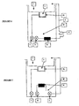
- This installation comprises, in a manner known per se, a unit 1 for washing the parts in which the cleaning fluid is loaded with organic materials in contact with the parts and a treatment unit 2 in which living microorganisms degrade the organic matter biologically. contained in the fluid from the washing unit 1. It is obvious that by piece, one hears all type of object.
- Loop circuit means a circuit that allows a flow of at least a portion of the fluid from the washing unit 1 to the treatment unit 2 on the one hand and from the unit 2 to the unit 1 on the other hand to allow to re-route at least a portion of the fluid from the unit 2 to the unit 1.
- the washing operation may take the form of a bath inside the washing unit 1 or by spraying cleaning fluid on the surface of the pieces. It is this second case which has been chosen in the embodiment shown in FIG.
- this installation further comprises, on the fluid circulation circuit, means 12 for at least partial sterilization of the microorganisms contained in at least a portion of the cleaning fluid.
- At least partial sterilization of the cleaning fluid makes it possible to limit or eliminate any contact between the microorganisms contained in the cleaning fluid and the hands of the operator. Thus, the risk of contamination, infection or allergy of the operator is reduced.
- These means 12 for sterilizing the cleaning fluid are preferably physical sterilization means capable of producing heat and / or radiation and / or ultraviolet, and / or chemically for a bactericidal action and or bacteriostatic on the microorganisms contained in the cleaning fluid.
- these sterilization means may be constituted by a UV lamp placed on the fluid circulation circuit, in particular on a pipe 4 for channeling the fluid which extends for example in the connection zone between the washing unit 1 and the treatment unit 2, this connection zone allowing a circulation of the cleaning fluid from the unit treatment to the washing unit 1.
- the sterilization means 12 extend, on the fluid circulation circuit, downstream of the treatment unit 2.
- these means 12 of sterilization can still be positioned in other locations of the installation as will be described below.
- These means 12 of sterilization can also be constituted by means of heating the fluid to cause destruction of microorganisms. In this case, the heating is preferably followed by a cooling of the fluid to dissipate the excess calories and maintain the fluid at the normal temperature of use between 20 and 40 ° C.
- these sterilization means may also be constituted by means for emitting radiation, in particular ultraviolet, causing the destruction of microorganisms. Sterilization can also be done chemically using chemical agents such as ozone. This sterilization can be total or partial. Partial or controlled sterilization will be referred to when the number of microorganisms, after treatment by sterilization of the fluid, is below a predetermined level but greater than zero.
- the number of microorganisms is kept below a defined threshold.
- Total or complete sterilization will be referred to when, after biological analysis, an absence of microorganisms is detected from a sample of cleaning fluid that has been subjected to this sterilization step.
- this sterilization can have a bacteriostatic action, that is to say simply prevent the growth of microorganisms present in the fluid, or a bactericidal action, that is to say, further destroy the microorganisms present in the fluid.
- the treatment unit 2 traversed by the cleaning fluid from the washing unit 1 comprises at least one treatment chamber, shown at 2A in the figures, filled with a material 3. filter on which the microorganisms are immobilized and through which the cleaning fluid generally circulates continuously to provide oxygenation of the necessary microorganisms to their development.
- the washing unit 1 has the shape of a sink inside which the parts 11 to be treated are placed on a grating 7 resting itself on a grid 8 extending over an outlet of the washing unit 1.
- This fluid discharge outlet positioned in the bottom of the tray or sink, is shaped so as to provide, inside the latter, on the one hand a siphon, on the other hand the chamber 2A of treatment of the treatment unit constituting a bioreactor.
- this discharge orifice delimits a chamber with generally perforated walls, integrating the filtering material 3 on which the microorganisms are immobilized.
- this filtering material may consist of woven or non-woven fabrics, geotextiles, fibers, ceramics, terra-cotta, clay, plastic or glass media, cellular foams, pozzolan, lithotam, metallurgical coke, siliceous pebbles.
- microorganisms immobilized on this support can in turn consist of the genera Achronobacter, Acinetobacter, Actinomyces, Alcaligenes, Bacillus, Flavobacterium, Klebsiella, Nocardia, Pseudomonas, Streptomyces, Vibrio, Xanthomyces, Aspergillus or other microorganisms that can participate in the biodegradation of hydrocarbons.
- This filter material 3 further contains nutrients for the microorganisms. These nutrients are preferably constituted by sources other than carbon sources and are preferably still insoluble or poorly soluble in the cleaning fluid. This constructive solution promotes the immobilization of the microorganisms on their support so that very few microorganisms are caused to detach from the support 3 and to circulate in the fluid. Nutrient sources may consist of phosphorus, nitrogen, oxygen, sulfur, magnesium, potassium, calcium, iron, manganese and other trace elements.
- the treatment chamber 2A of the treatment unit 2 inside which the aqueous cleaning fluid is treated by contact with microorganisms, communicates with a 2B chamber for recovery and storage of at least partially purified fluid from the processing chamber 2A.
- This chamber 2B or 2B2 treated fluid recovery can be compartmentalized, the compartments communicating with each other overflow.
- This treated fluid recovery chamber 2B, 2B2 is equipped on the one hand with a fluid recirculation circuit 5 to the treatment chamber 2A, on the other hand with means 4 for direct or indirect connection with the unit 1 of the fluid. washing in order to circulate the fluid towards the washing unit 1.
- These connecting means 4 or circulation loop 5 are for example constituted by a fluid circulation duct inside which the fluid is driven in displacement by means of a pump.
- the fluid circulation loop 5 between the treated fluid recovery chamber 2B or 2B2 and the treatment unit treatment chamber 2A is constituted by a pump 9 that sucks out the fluid. contained inside the chamber 2B or 2B2 to cause it to flow through a pipe until introduction into the chamber 2A where it can flow again through the support 3 and thus be again in contact with microorganisms capable of treating the fluid and decontaminating it.
- This fluid then returns to chamber 2B or 2B2.
- the connection means 4 between the treated fluid recovery chamber 2B of the treatment unit 2 and the cleaning unit 1 are constituted by a pipe shown at 4 in FIGS. .
- This pipe 4 is equipped with a fluid suction pump 6 contained in the chamber 2B in order to bring this fluid inside the cleaning unit 1. This fluid is thus projected via a brush 10 on the part 11 to be cleaned. The cleaning fluid thus loaded with organic material is then discharged from the washing unit 1 to the processing chamber 2A of the treatment unit and a new cycle can begin.
- the pumps 6 and 9 used are preferably submerged turbine pumps. This turbine is housed inside a stator capable of creating a magnetic field cooperating with the magnetic axis with hydrodynamic lubrication of rotation of the turbine.
- the sterilization means 12 are positioned on the circuit 5 for recirculating fluid between the first and the second chamber of the treatment unit 2.
- the sterilization means 12 may be positioned on the connection means 4 between the treatment unit 2 and the washing unit 1 and / or in one of the chambers of the treatment unit. treatment and / or on the connection between two chambers of the treatment unit.
- the fluid pumped into the chamber 2B via the pump 9 and re-circulating through the pipe 5 to be brought to the chamber 2A of the unit 2 of treatment circulates through an ultraviolet radiation lamp 12 which ensures at least partial sterilization of the fluid flowing inside said pipe.
- the fluid contained in the chamber 2B is a sterile or quasi-sterile fluid.
- the sterilization means 12 are positioned between the first and the second chamber of the treatment unit so that the fluid coming from the treatment chamber 2A reaches the second chamber. room 2B is sterile.
- a collector 13 adapted to channel the cleaning fluid from the processing chamber 2A, the channelized fluid passing through a pipe equipped with a lamp 12 ultraviolet radiation to sterilize the fluid for opening into the second chamber 2B.
- the sterilization means As illustrated in FIG. 5, it is also possible to position the sterilization means immediately downstream of the pump 6 or 9 used to suck up the fluid from the treated fluid recovery chamber 2B of the treatment unit in the direction of the processing chamber 2A of the processing unit. It is also provided, downstream of these sterilization means, a stitching for connecting the contents of the chamber 2B with the washing unit 1.
- the same pump shown at 6 and 9 in Figure 5, serves both the cleaning fluid supply of the chamber 2A and the washing unit 1.
- a circuit selector preferably consisting of a valve actuated either manually by the operator, or automatically according to a principle of hydraulic valve distributor with spring return tared to a given value, or a solenoid valve controlled by manual or automatic control instructions, optionally supplying the chamber 2A or the washing unit 1.
- the means 12 for sterilization can still be positioned in the connecting pipe between the treatment unit 2 and the washing unit 1, this connecting pipe 4 allowing the circulation of the cleaning fluid from the treatment unit 2 to the treatment unit 1. washing unit 1.
- This example corresponds to that shown in Figure 6 where the sterilization means are positioned on the pipe 4 extending between the pump 6 for sucking the fluid into the chamber 2B, and the washing unit 1.
- these means 12 for sterilization consist of heating means, cooling means 15 are preferably associated with them in order to maintain the fluid at the normal temperature of use between 20 and 40 ° C.
- the sterilization means are positioned in the fluid recovery chamber 2B. treated unit 2 treatment.
- the chamber 2B is kept sterile or quasi-sterile by the circulation of the fluid in the sterilization means 12 by means of a pump 10 introducing a loop circulation of the fluid inside said chamber.
- FIGS 8 and 9 illustrate two other embodiments of the invention in which the chamber number of the processing unit 2 has been increased.
- the treatment chamber 2A of the treatment unit 2 inside which the cleaning fluid is treated by contact with living microorganisms, communicates with a recovery chamber 2B2. and storing the fluid from the treatment chamber 2A.
- This chamber 2B2 is equipped with means for recirculating fluid to the treatment chamber 2A.
- This chamber 2B2 communicates with an additional chamber 2B1 constituting the interface of the chambers 2, 2A, 2B2 of the treatment unit 2 with the washing unit 1.
- the chamber 2B2 is itself supplied with fluid from the washing unit 1 from a chamber 2B1.
- This interface chamber 2B1 comprises means 4 for connection with the washing unit 1 for the circulation of the fluid towards the washing unit 1.
- This interface chamber 2B1 between the other chambers of the treatment unit 2 and the washing unit 1 feeds at least one of the other chambers of the processing unit via, for example, a device 14. deoiling.
- This device makes it possible to extract the light phase of the biphasic fluid coming from the washing unit 1.
- This device comprises means for extracting the light phase and control means in operation of said extraction means.
- control means in operation of the extraction means are constituted for example on the one hand by two floats able to float one on the surface of the light phase, the other on the surface of the heavy phase, on the other hand part of at least one sensor whose activation authorizing the start or stop of the extraction means is slaved to the relative positioning of said floats.
- These extraction means are not examples consisting of an evacuation duct provided at its end with a float maintaining the outlet of said duct end in the phase to be extracted, this duct being equipped with an organ shutter, such as a valve controlled opening and closing by said sensor. The shutter member is controlled in opening when the distance separating the two floats of the control means, detected by said sensor, is greater than a predetermined value.
- the cleaning fluid from the washing unit 1 and loaded with organic material flows into the interface chamber 2B1 which feeds, via the de-oiling device 14, the chamber 2B2 equipped with a fluid recirculation circuit with the treatment chamber 2A of the treatment unit 2.
- the fluid is pumped via a pump 16 and redirected into the interface chamber 2B1.
- means 12 for sterilization are provided on this link between the chambers 2B2 and 2B1.
- the sterilization means are positioned on the link between two chambers of the treatment unit 2.
- these chambers 2B2 and 2A have, moreover, been designed so as to be made in the form of an outer unit relative to the washing unit and to the chamber 2B1 so as to be well physically separate the elements able to contain micro-organisms and those normally free of micro-organisms or at least containing them in an insufficient quantity to generate a contamination.
- FIG. 9 illustrates another embodiment of the invention in which the fluid coming from the washing unit 1 feeds the interface chamber 2B1 which itself feeds, by a de-oiling device 14, the chamber 2B2.
- This communication chamber 2B2 is again equipped with a fluid recirculation circuit with the processing chamber 2A of the treatment unit 2. Once the fluid has been treated, this fluid is returned to the chamber 2B1. Again, means 12 for sterilization are positioned on the link between the chambers 2B2 and 2B1.
- a pump 6 allows, via a line 4, to extract the fluid from this interface chamber 2B1 in order to bring it to the washing unit 1.
Landscapes
- Health & Medical Sciences (AREA)
- Public Health (AREA)
- General Health & Medical Sciences (AREA)
- Veterinary Medicine (AREA)
- Epidemiology (AREA)
- Life Sciences & Earth Sciences (AREA)
- Animal Behavior & Ethology (AREA)
- Chemical & Material Sciences (AREA)
- General Chemical & Material Sciences (AREA)
- Chemical Kinetics & Catalysis (AREA)
- Apparatus For Disinfection Or Sterilisation (AREA)
- Cleaning Or Drying Semiconductors (AREA)
- Treatments Of Macromolecular Shaped Articles (AREA)
- Physical Water Treatments (AREA)
- Micro-Organisms Or Cultivation Processes Thereof (AREA)
- Detergent Compositions (AREA)
Claims (13)
- Verfahren zur Reinigung, insbesondere zur Entfettung oder Entölung von mit organischem Material verunreinigten Teilen mithilfe einer Reinigungsflüssigkeit, von der mindestens ein Teil im geschlossenen Kreislauf zwischen einer Teilewascheinheit (1), in der die Reinigungsflüssigkeit an den Teilen anliegendes organisches Material aufnimmt, und einer Behandlungseinheit (2) umläuft, in der lebende Mikroorganismen das organische Material, das in der Flüssigkeit aus der Wascheinheit (1) enthalten ist, biologisch abbauen, dadurch gekennzeichnet, dass mindestens ein Teil der Reinigungsflüssigkeit, die in der genannten Anlage umläuft, zumindest teilweise sterilisiert wird, um das Vorhandensein von lebenden Mikroorganismen in der Reinigungsflüssigkeit, die der Wascheinheit (1) zugeführt wird, zu begrenzen und sogar auszuschließen.
- Anlage für die Reinigung, insbesondere zur Entfettung oder Entölung von mit organischem Material verunreinigten Teilen mithilfe einer Reinigungsflüssigkeit, die eine Teilewascheinheit (1), in der die Reinigungsflüssigkeit an den Teilen anliegendes organisches Material aufnimmt, eine Behandlungseinheit (2), in der lebende Mikroorganismen das organische Material, das in der Flüssigkeit aus der Wascheinheit (1) enthalten ist, biologisch abbauen, und Mittel umfasst, die für den Umlauf der Reinigungsflüssigkeit im geschlossenen Kreislauf zwischen der Wascheinheit (1) und der Behandlungseinheit (2) sorgen und somit einen Flüssigkeitskreislauf bilden, dadurch gekennzeichnet, dass die Anlage im Flüssigkeitskreislauf zudem Sterilisationsmittel (12) umfasst, die die Mikroorganismen, die in mindestens einem Teil der Reinigungsflüssigkeit enthalten sind, zumindest teilweise abtöten.
- Anlage nach Anspruch 2, in der die Mittel (12) zur Sterilisation der Reinigungsflüssigkeit Mittel zur Sterilisation auf physikalischem Wege durch Erzeugung von Hitze und/oder Strahlung und/oder W-Strahlen und/oder auf chemischem Wege durch bakterizide und/oder bakteriostatische Wirkung auf die in der Reinigungsflüssigkeit enthaltenen Mikroorganismen sind.
- Anlage nach einem der Ansprüche 2 und 3, in der die Behandlungseinheit (2), durch die die Reinigungsflüssigkeit aus der Wascheinheit (1) fließt, mindestens eine Behandlungskammer (2A) umfasst, die mit einem Filtermaterial (3) gefüllt ist, an dem die lebenden Mikroorganismen aufgehalten werden und durch das die Reinigungsflüssigkeit umläuft.
- Anlage nach Anspruch 4, in der das Filtermaterial (3) zudem Nährstoffe für die Mikroorganismen enthält, wobei die Nährstoffe, die vorzugsweise nicht aus carbonierten Quellen stammen, in der Reinigungsflüssigkeit vorzugsweise nicht oder schlecht löslich sind.
- Anlage nach Anspruch 4, in der die Behandlungskammer (2A) der Behandlungseinheit (2), in der die Reinigungsflüssigkeit durch Kontakt mit lebenden Mikroorganismen behandelt wird, mit einer Kammer (2B) für die Rückgewinnung und Speicherung der Flüssigkeit aus der Behandlungskammer (2A) verbunden ist, wobei die Kammer (2B) einerseits mit einem Kreislauf (5) für den Rückumlauf der Flüssigkeit zur Behandlungskammer (2A) und andererseits mit Mitteln (4) zur Verbindung mit der Wascheinheit (1) ausgerüstet ist, damit die Flüssigkeit zur Wascheinheit (1) fließt.
- Anlage nach Anspruch 4, in der die Behandlungskammer (2A) der Behandlungseinheit (2), in der die Reinigungsflüssigkeit durch Kontakt mit lebenden Mikroorganismen behandelt wird, mit einer Kammer (2B2) für die Rückgewinnung und Speicherung der Flüssigkeit aus der ersten Behandlungskammer (2A) verbunden ist, wobei die Kammer (2B2) mit einem Kreislauf (5) für den Rückumlauf der Flüssigkeit zur Behandlungskammer (2A) verbunden ist, die selbst mit einer zusätzlichen Kammer (2B1) verbunden ist, die eine Verbindungskammer zwischen den anderen Kammern der Behandlungseinheit und der Wascheinheit bildet, wobei die Verbindungskammer (2B1) Mittel (4) zur Verbindung mit der Wascheinheit (1) umfasst, damit die Flüssigkeit zur Wascheinheit (1) fließt.
- Anlage nach Anspruch 7, in der die Verbindungskammer (2B1) zwischen den anderen Kammern der Behandlungseinheit (2) und der Wascheinheit (1) die anderen Kammern der Behandlungseinheit über eine Entölungsvorrichtung (14) mit Flüssigkeit versorgt.
- Anlage nach einem der Ansprüche 6 oder 7, in der die Sterilisationsmittel (12) in der Verbindung zwischen zwei Kammern der Behandlungseinheit, insbesondere im Kreislauf (5) für den Rückumlauf der Flüssigkeit zwischen der Behandlungskammer (2A) und der Kammer (2B, 2B2) für die Rückgewinnung und Speicherung der Flüssigkeit aus der Behandlungskammer (2A) und/oder in den Verbindungsmitteln (4) zwischen der Behandlungseinheit (2) und der Wascheinheit (1) und/oder in einer der Kammern der Behandlungseinheit (2) angebracht sind.
- Anlage nach Anspruch 9, in der die Sterilisationsmittel (12) zwischen der Behandlungskammer (2A) und der Kammer (2B, 2B2) für die Rückgewinnung und Speicherung der behandelten Flüssigkeit aus der Behandlungskammer (2) angebracht sind, sodass die Flüssigkeit aus der Behandlungskammer (2A), die in die andere Kammer (2B, 2B2) fließt, steril ist.
- Anlage nach einem der Ansprüche 6 bis 10, in der die Behandlungskammer (2A) der Behandlungseinheit (2) hängend über der Kammer (2B, 2B2) für die Speicherung der behandelten Flüssigkeit aus der Behandlungseinheit (2) angebracht ist.
- Anlage nach einem der Ansprüche 4 bis 11, in der die Wascheinheit (1) mit einem Auslauf für die Flüssigkeit ausgerüstet ist, in dem die Behandlungskammer (2A) der Behandlungseinheit (2) untergebracht ist.
- Anlage nach einem der Ansprüche 2 bis 7, in der die Behandlungseinheit (2) mit Mitteln (4) für die Verbindung mit der Wascheinheit (1) ausgerüstet ist, damit die Flüssigkeit zur Wascheinheit (1) fließt, wobei die Sterilisationsmittel (12) in der Verbindungsleitung zwischen den Einheiten (2, 1) angebracht sind.
Applications Claiming Priority (2)
| Application Number | Priority Date | Filing Date | Title |
|---|---|---|---|
| FR0305864A FR2854824B1 (fr) | 2003-05-16 | 2003-05-16 | Procede et installation pour le nettoyage de pieces souillees par de la matiere organique par bio-depollution |
| PCT/FR2004/001155 WO2004103584A2 (fr) | 2003-05-16 | 2004-05-12 | Procede et installation pour le nettoyage de pieces souillees par de la matiere organique |
Publications (2)
| Publication Number | Publication Date |
|---|---|
| EP1631394A2 EP1631394A2 (de) | 2006-03-08 |
| EP1631394B1 true EP1631394B1 (de) | 2007-03-21 |
Family
ID=33306389
Family Applications (1)
| Application Number | Title | Priority Date | Filing Date |
|---|---|---|---|
| EP04742711A Expired - Lifetime EP1631394B1 (de) | 2003-05-16 | 2004-05-12 | Verfahren und einheit zur reinigung von mit organischem material verunreinigten teilen |
Country Status (7)
| Country | Link |
|---|---|
| US (1) | US20060278255A1 (de) |
| EP (1) | EP1631394B1 (de) |
| AT (1) | ATE357298T1 (de) |
| CA (1) | CA2525288A1 (de) |
| DE (1) | DE602004005452T2 (de) |
| FR (1) | FR2854824B1 (de) |
| WO (1) | WO2004103584A2 (de) |
Families Citing this family (7)
| Publication number | Priority date | Publication date | Assignee | Title |
|---|---|---|---|---|
| EP1872875B1 (de) | 2006-06-30 | 2012-06-20 | Ulrich Berens | Vorrichtung zur Reinigung von mit Öl oder Fett verschmutzten Maschinenteilen, nach Art einer Waschmaschine |
| DE102007034464B4 (de) * | 2007-07-20 | 2011-07-14 | ph-cleantec GmbH, 70736 | Reinigungsgerät |
| JP2019510036A (ja) | 2016-03-31 | 2019-04-11 | ゴジョ・インダストリーズ・インコーポレイテッド | プロバイオティクス/プレバイオティクス有効成分を含む清浄剤組成物 |
| EP3435765A1 (de) | 2016-03-31 | 2019-02-06 | Gojo Industries, Inc. | Desinfektionszusammensetzung zur stimulation von antimikrobiellen peptiden |
| US10806769B2 (en) | 2016-03-31 | 2020-10-20 | Gojo Industries, Inc. | Antimicrobial peptide stimulating cleansing composition |
| US11564879B2 (en) | 2016-11-23 | 2023-01-31 | Gojo Industries, Inc. | Sanitizer composition with probiotic/prebiotic active ingredient |
| FR3107662A1 (fr) * | 2020-03-02 | 2021-09-03 | Pictura Innovation | Dispositif autonome de nettoyage d'outils |
Family Cites Families (4)
| Publication number | Priority date | Publication date | Assignee | Title |
|---|---|---|---|---|
| US5254246A (en) * | 1991-07-16 | 1993-10-19 | Sonia Rivelli | Water reclamation system |
| DE4209052A1 (de) * | 1991-08-16 | 1993-02-25 | Peter Prof Dr Kunz | Anlage und verfahren zur mikrobiellen entfettung/entoelung von oberflaechen |
| WO1996011071A2 (en) * | 1994-09-30 | 1996-04-18 | Chemfree Corporation | Parts washing system |
| US6571810B1 (en) * | 1994-09-30 | 2003-06-03 | Zymo International, Inc. | Parts washing system |
-
2003
- 2003-05-16 FR FR0305864A patent/FR2854824B1/fr not_active Expired - Fee Related
-
2004
- 2004-05-12 AT AT04742711T patent/ATE357298T1/de not_active IP Right Cessation
- 2004-05-12 US US10/556,824 patent/US20060278255A1/en not_active Abandoned
- 2004-05-12 DE DE602004005452T patent/DE602004005452T2/de not_active Expired - Fee Related
- 2004-05-12 WO PCT/FR2004/001155 patent/WO2004103584A2/fr not_active Ceased
- 2004-05-12 EP EP04742711A patent/EP1631394B1/de not_active Expired - Lifetime
- 2004-05-12 CA CA002525288A patent/CA2525288A1/fr not_active Abandoned
Also Published As
| Publication number | Publication date |
|---|---|
| WO2004103584A3 (fr) | 2005-01-27 |
| FR2854824A1 (fr) | 2004-11-19 |
| US20060278255A1 (en) | 2006-12-14 |
| CA2525288A1 (fr) | 2004-12-02 |
| WO2004103584A2 (fr) | 2004-12-02 |
| DE602004005452T2 (de) | 2007-11-29 |
| FR2854824B1 (fr) | 2005-07-08 |
| ATE357298T1 (de) | 2007-04-15 |
| DE602004005452D1 (de) | 2007-05-03 |
| EP1631394A2 (de) | 2006-03-08 |
Similar Documents
| Publication | Publication Date | Title |
|---|---|---|
| EP0784518B2 (de) | Vorrichtung zum mikrobiologischen waschen von teilen | |
| CN1649630A (zh) | 自动内窥镜再处理器 | |
| JP2005506076A (ja) | 水産養殖系で水を処理するための方法および手段 | |
| CN1886085A (zh) | 具有水处理系统的洗碗机 | |
| EP1631394A2 (de) | Verfahren und einheit zur reinigung von mit organischem material verunreinigten teilen | |
| FR2657277A1 (fr) | Procede et installation de nettoyage de lampes a rayons ultraviolets utilises pour la desinfection d'eaux usees. | |
| JP4555081B2 (ja) | 船舶用海水の処理方法及び装置 | |
| US20200339448A1 (en) | Fluid Treatment System and Method | |
| FR2799456A1 (fr) | Dispositif de traitement de l'eau destine a augmenter la solubilite de l'oxygene dans l'eau potable ultra pure | |
| Ramos et al. | Ultraviolet control of bacterial biofilms in microfluidic chips | |
| KR20140103609A (ko) | 선박 및 양식장용 오수처리장치 | |
| JP4290854B2 (ja) | 廃水処理装置及び廃水処理方法 | |
| US7972500B2 (en) | Waste water purification apparatus | |
| WO2012080673A1 (fr) | Procédé et appareillage pour la désinfection de l'eau | |
| CA2267677C (en) | Fluid treatment system | |
| FR3070975B1 (fr) | Reacteur et procede de traitement biologique des eaux residuaires | |
| KR100521805B1 (ko) | 순환기능이 부가된 단체급수용 음수공급장치 | |
| US6746646B2 (en) | Method and apparatus for the disinfecting biosolids | |
| WO2007144544A1 (fr) | Procede, dispositif et installation pour la decontamination d'un fluide caloriporteur | |
| CN221479738U (zh) | 矿山污水处理一体化设备 | |
| KR101849088B1 (ko) | 정수기 내부 유로의 살균방법 | |
| CN109020048A (zh) | 一种锂电池废水初期处理一体化装置 | |
| KR100949346B1 (ko) | 슬러지 처리장치 | |
| FR2864067A1 (fr) | Procede de traitement biologique d'un effluent et dispositif de preparation de micro-organismes servant au traitement biologique d'un effluent. | |
| KR101729317B1 (ko) | 해수 및 담수의 순환 여과 방법 |
Legal Events
| Date | Code | Title | Description |
|---|---|---|---|
| PUAI | Public reference made under article 153(3) epc to a published international application that has entered the european phase |
Free format text: ORIGINAL CODE: 0009012 |
|
| 17P | Request for examination filed |
Effective date: 20051116 |
|
| AK | Designated contracting states |
Kind code of ref document: A2 Designated state(s): AT BE BG CH CY CZ DE DK EE ES FI FR GB GR HU IE IT LI LU MC NL PL PT RO SE SI SK TR |
|
| DAX | Request for extension of the european patent (deleted) | ||
| GRAP | Despatch of communication of intention to grant a patent |
Free format text: ORIGINAL CODE: EPIDOSNIGR1 |
|
| GRAS | Grant fee paid |
Free format text: ORIGINAL CODE: EPIDOSNIGR3 |
|
| GRAA | (expected) grant |
Free format text: ORIGINAL CODE: 0009210 |
|
| AK | Designated contracting states |
Kind code of ref document: B1 Designated state(s): AT BE BG CH CY CZ DE DK EE ES FI FR GB GR HU IE IT LI LU MC NL PL PT RO SE SI SK TR |
|
| PG25 | Lapsed in a contracting state [announced via postgrant information from national office to epo] |
Ref country code: FI Free format text: LAPSE BECAUSE OF FAILURE TO SUBMIT A TRANSLATION OF THE DESCRIPTION OR TO PAY THE FEE WITHIN THE PRESCRIBED TIME-LIMIT Effective date: 20070321 Ref country code: IE Free format text: LAPSE BECAUSE OF FAILURE TO SUBMIT A TRANSLATION OF THE DESCRIPTION OR TO PAY THE FEE WITHIN THE PRESCRIBED TIME-LIMIT Effective date: 20070321 Ref country code: AT Free format text: LAPSE BECAUSE OF FAILURE TO SUBMIT A TRANSLATION OF THE DESCRIPTION OR TO PAY THE FEE WITHIN THE PRESCRIBED TIME-LIMIT Effective date: 20070321 Ref country code: PL Free format text: LAPSE BECAUSE OF FAILURE TO SUBMIT A TRANSLATION OF THE DESCRIPTION OR TO PAY THE FEE WITHIN THE PRESCRIBED TIME-LIMIT Effective date: 20070321 Ref country code: NL Free format text: LAPSE BECAUSE OF FAILURE TO SUBMIT A TRANSLATION OF THE DESCRIPTION OR TO PAY THE FEE WITHIN THE PRESCRIBED TIME-LIMIT Effective date: 20070321 Ref country code: SI Free format text: LAPSE BECAUSE OF FAILURE TO SUBMIT A TRANSLATION OF THE DESCRIPTION OR TO PAY THE FEE WITHIN THE PRESCRIBED TIME-LIMIT Effective date: 20070321 |
|
| REG | Reference to a national code |
Ref country code: GB Ref legal event code: FG4D Free format text: NOT ENGLISH |
|
| REG | Reference to a national code |
Ref country code: CH Ref legal event code: EP |
|
| REF | Corresponds to: |
Ref document number: 602004005452 Country of ref document: DE Date of ref document: 20070503 Kind code of ref document: P |
|
| REG | Reference to a national code |
Ref country code: IE Ref legal event code: FG4D Free format text: LANGUAGE OF EP DOCUMENT: FRENCH |
|
| PG25 | Lapsed in a contracting state [announced via postgrant information from national office to epo] |
Ref country code: SE Free format text: LAPSE BECAUSE OF FAILURE TO SUBMIT A TRANSLATION OF THE DESCRIPTION OR TO PAY THE FEE WITHIN THE PRESCRIBED TIME-LIMIT Effective date: 20070621 |
|
| PG25 | Lapsed in a contracting state [announced via postgrant information from national office to epo] |
Ref country code: ES Free format text: LAPSE BECAUSE OF FAILURE TO SUBMIT A TRANSLATION OF THE DESCRIPTION OR TO PAY THE FEE WITHIN THE PRESCRIBED TIME-LIMIT Effective date: 20070702 |
|
| GBT | Gb: translation of ep patent filed (gb section 77(6)(a)/1977) |
Effective date: 20070622 |
|
| PG25 | Lapsed in a contracting state [announced via postgrant information from national office to epo] |
Ref country code: PT Free format text: LAPSE BECAUSE OF FAILURE TO SUBMIT A TRANSLATION OF THE DESCRIPTION OR TO PAY THE FEE WITHIN THE PRESCRIBED TIME-LIMIT Effective date: 20070821 |
|
| REG | Reference to a national code |
Ref country code: GB Ref legal event code: 711B |
|
| NLV1 | Nl: lapsed or annulled due to failure to fulfill the requirements of art. 29p and 29m of the patents act | ||
| REG | Reference to a national code |
Ref country code: IE Ref legal event code: FD4D |
|
| PG25 | Lapsed in a contracting state [announced via postgrant information from national office to epo] |
Ref country code: SK Free format text: LAPSE BECAUSE OF FAILURE TO SUBMIT A TRANSLATION OF THE DESCRIPTION OR TO PAY THE FEE WITHIN THE PRESCRIBED TIME-LIMIT Effective date: 20070321 |
|
| BERE | Be: lapsed |
Owner name: CLEAN 3 BIO SYSTEM Effective date: 20070531 |
|
| PG25 | Lapsed in a contracting state [announced via postgrant information from national office to epo] |
Ref country code: CZ Free format text: LAPSE BECAUSE OF FAILURE TO SUBMIT A TRANSLATION OF THE DESCRIPTION OR TO PAY THE FEE WITHIN THE PRESCRIBED TIME-LIMIT Effective date: 20070321 Ref country code: RO Free format text: LAPSE BECAUSE OF FAILURE TO SUBMIT A TRANSLATION OF THE DESCRIPTION OR TO PAY THE FEE WITHIN THE PRESCRIBED TIME-LIMIT Effective date: 20070321 |
|
| PLBE | No opposition filed within time limit |
Free format text: ORIGINAL CODE: 0009261 |
|
| STAA | Information on the status of an ep patent application or granted ep patent |
Free format text: STATUS: NO OPPOSITION FILED WITHIN TIME LIMIT |
|
| PG25 | Lapsed in a contracting state [announced via postgrant information from national office to epo] |
Ref country code: MC Free format text: LAPSE BECAUSE OF NON-PAYMENT OF DUE FEES Effective date: 20070531 Ref country code: DK Free format text: LAPSE BECAUSE OF FAILURE TO SUBMIT A TRANSLATION OF THE DESCRIPTION OR TO PAY THE FEE WITHIN THE PRESCRIBED TIME-LIMIT Effective date: 20070321 |
|
| 26N | No opposition filed |
Effective date: 20071227 |
|
| PG25 | Lapsed in a contracting state [announced via postgrant information from national office to epo] |
Ref country code: BE Free format text: LAPSE BECAUSE OF NON-PAYMENT OF DUE FEES Effective date: 20070531 |
|
| PG25 | Lapsed in a contracting state [announced via postgrant information from national office to epo] |
Ref country code: IT Free format text: LAPSE BECAUSE OF FAILURE TO SUBMIT A TRANSLATION OF THE DESCRIPTION OR TO PAY THE FEE WITHIN THE PRESCRIBED TIME-LIMIT Effective date: 20070321 Ref country code: GR Free format text: LAPSE BECAUSE OF FAILURE TO SUBMIT A TRANSLATION OF THE DESCRIPTION OR TO PAY THE FEE WITHIN THE PRESCRIBED TIME-LIMIT Effective date: 20070622 |
|
| REG | Reference to a national code |
Ref country code: GB Ref legal event code: S117 |
|
| REG | Reference to a national code |
Ref country code: CH Ref legal event code: PL |
|
| PG25 | Lapsed in a contracting state [announced via postgrant information from national office to epo] |
Ref country code: LI Free format text: LAPSE BECAUSE OF NON-PAYMENT OF DUE FEES Effective date: 20080531 Ref country code: CH Free format text: LAPSE BECAUSE OF NON-PAYMENT OF DUE FEES Effective date: 20080531 Ref country code: EE Free format text: LAPSE BECAUSE OF FAILURE TO SUBMIT A TRANSLATION OF THE DESCRIPTION OR TO PAY THE FEE WITHIN THE PRESCRIBED TIME-LIMIT Effective date: 20070321 |
|
| PG25 | Lapsed in a contracting state [announced via postgrant information from national office to epo] |
Ref country code: CY Free format text: LAPSE BECAUSE OF FAILURE TO SUBMIT A TRANSLATION OF THE DESCRIPTION OR TO PAY THE FEE WITHIN THE PRESCRIBED TIME-LIMIT Effective date: 20070321 |
|
| PG25 | Lapsed in a contracting state [announced via postgrant information from national office to epo] |
Ref country code: LU Free format text: LAPSE BECAUSE OF NON-PAYMENT OF DUE FEES Effective date: 20070512 Ref country code: BG Free format text: LAPSE BECAUSE OF FAILURE TO SUBMIT A TRANSLATION OF THE DESCRIPTION OR TO PAY THE FEE WITHIN THE PRESCRIBED TIME-LIMIT Effective date: 20070621 |
|
| PGFP | Annual fee paid to national office [announced via postgrant information from national office to epo] |
Ref country code: DE Payment date: 20090531 Year of fee payment: 6 |
|
| PG25 | Lapsed in a contracting state [announced via postgrant information from national office to epo] |
Ref country code: TR Free format text: LAPSE BECAUSE OF FAILURE TO SUBMIT A TRANSLATION OF THE DESCRIPTION OR TO PAY THE FEE WITHIN THE PRESCRIBED TIME-LIMIT Effective date: 20070321 Ref country code: HU Free format text: LAPSE BECAUSE OF FAILURE TO SUBMIT A TRANSLATION OF THE DESCRIPTION OR TO PAY THE FEE WITHIN THE PRESCRIBED TIME-LIMIT Effective date: 20070922 |
|
| PGFP | Annual fee paid to national office [announced via postgrant information from national office to epo] |
Ref country code: GB Payment date: 20090521 Year of fee payment: 6 |
|
| GBPC | Gb: european patent ceased through non-payment of renewal fee |
Effective date: 20100512 |
|
| PG25 | Lapsed in a contracting state [announced via postgrant information from national office to epo] |
Ref country code: DE Free format text: LAPSE BECAUSE OF NON-PAYMENT OF DUE FEES Effective date: 20101201 |
|
| PG25 | Lapsed in a contracting state [announced via postgrant information from national office to epo] |
Ref country code: GB Free format text: LAPSE BECAUSE OF NON-PAYMENT OF DUE FEES Effective date: 20100512 |
|
| PGFP | Annual fee paid to national office [announced via postgrant information from national office to epo] |
Ref country code: FR Payment date: 20130603 Year of fee payment: 10 |
|
| REG | Reference to a national code |
Ref country code: FR Ref legal event code: ST Effective date: 20150130 |
|
| PG25 | Lapsed in a contracting state [announced via postgrant information from national office to epo] |
Ref country code: FR Free format text: LAPSE BECAUSE OF NON-PAYMENT OF DUE FEES Effective date: 20140602 |