EP1631068A2 - Vorrichtung und Verfahren zur Umwandlung von Zeilensprungbildern zu progressiven Bildern - Google Patents
Vorrichtung und Verfahren zur Umwandlung von Zeilensprungbildern zu progressiven Bildern Download PDFInfo
- Publication number
- EP1631068A2 EP1631068A2 EP04255997A EP04255997A EP1631068A2 EP 1631068 A2 EP1631068 A2 EP 1631068A2 EP 04255997 A EP04255997 A EP 04255997A EP 04255997 A EP04255997 A EP 04255997A EP 1631068 A2 EP1631068 A2 EP 1631068A2
- Authority
- EP
- European Patent Office
- Prior art keywords
- object pixel
- pixels
- values
- value
- image
- Prior art date
- Legal status (The legal status is an assumption and is not a legal conclusion. Google has not performed a legal analysis and makes no representation as to the accuracy of the status listed.)
- Withdrawn
Links
Images


Classifications
-
- H—ELECTRICITY
- H04—ELECTRIC COMMUNICATION TECHNIQUE
- H04N—PICTORIAL COMMUNICATION, e.g. TELEVISION
- H04N7/00—Television systems
- H04N7/01—Conversion of standards, e.g. involving analogue television standards or digital television standards processed at pixel level
- H04N7/0117—Conversion of standards, e.g. involving analogue television standards or digital television standards processed at pixel level involving conversion of the spatial resolution of the incoming video signal
- H04N7/012—Conversion between an interlaced and a progressive signal
-
- H—ELECTRICITY
- H04—ELECTRIC COMMUNICATION TECHNIQUE
- H04N—PICTORIAL COMMUNICATION, e.g. TELEVISION
- H04N5/00—Details of television systems
- H04N5/14—Picture signal circuitry for video frequency region
- H04N5/144—Movement detection
-
- H—ELECTRICITY
- H04—ELECTRIC COMMUNICATION TECHNIQUE
- H04N—PICTORIAL COMMUNICATION, e.g. TELEVISION
- H04N7/00—Television systems
- H04N7/01—Conversion of standards, e.g. involving analogue television standards or digital television standards processed at pixel level
- H04N7/0135—Conversion of standards, e.g. involving analogue television standards or digital television standards processed at pixel level involving interpolation processes
Definitions
- the present invention relates to an apparatus and method for converting an interlaced image into a progressive image, and more particularly, to an apparatus and method for converting an interlaced image into a progressive image by interpolating the interlaced image considering characteristics of a region and the orientation of an edge to which a pixel to be interpolated belongs.
- interpolation is performed on an object pixel, using the values of pixels on preceding and following interlaced scan line corresponding to the object pixel and the values of upper and lower pixels above and below the object pixel, and the result of interpolation is used as the value of the object pixel.
- the blend method is preferred since an edge of an image can be smoothly and naturally represented. However, when an interlaced image with much motion is converted into a progressive image using the blend method, a blur and an afterimage are likely to occur, and diagonal aliasing may occur at an edge of the image.
- the value of an object pixel is obtained using the values of pixels above and below the object pixel and the values of pixels to the left and right of the pixels above and below the object pixel.
- a value obtained by progressively scanning an object pixel X is computed using the value D lu of a pixel to the upper left of the object pixel, the value D rd of a pixel to the lower right of the object pixel, the value D ru of a pixel to the upper right of the object pixel, and the value D ld of a pixel to the lower left of the object pixel, and the values V u and V d of pixels above and below the object pixel.
- the value obtained by progressively scanning an object pixel X is obtained by computing the differences between the values V u and V d , between the values D lu and D rd , and between the values D ru and D ld , and then interpolating the object pixel X using pixels disposed in a direction having the smallest value among these differences.
- This method is advantageous in that slanted edges of an image can be naturally represented since image conversion is made in consideration of pixels disposed diagonally from the object pixel, thus preventing aliasing from occurring in the image.
- the edge dependent interpolation method is disadvantageous in that the edge orientation in an image is likely to be erroneously determined and use of only one field of an interlaced image during interpolation may cause a large difference between chromaticity values of the interlaced image and a progressive image. Also, color blurring may occur during conversion of an image having an object moving fast into a progressive image. Accordingly, the edge dependent interpolation method requires determining whether a pixel is to be interpolated in a diagonal direction or a vertical direction.
- the edge orientation in an image is determined by computing absolute values
- of the differences between values of pixels along an upper scan line and pixels of a lower scan line (k -N, ..., 0, ..., N), and determining that there is a diagonal line in the direction in which the smallest absolute value is obtained.
- Such a method is disclosed in U.S. Patent Nos. 5532751 and 6421090.
- this method requires complex computation to obtain the absolute values of the differences between the values of possible combinations of pixels disposed diagonally from an object pixel.
- motion estimation needed for precise image conversion requires a lot of computation and large memory bandwidth, thus making it difficult to convert an interlaced image into a progressive image in real time.
- an apparatus for converting an interlaced image into a progressive image comprising: a motion detector which detects motion at an object pixel of the interlaced field image, using proceeding and following field images; an interpolation direction determination unit which determines a direction in which the object pixel is to be interpolated, using values of pixels along scan lines where the object pixel is not located when motion at the object pixel is detected; a first interpolator which spatially interpolates the object pixel according to the determined direction; and a second interpolator which resets a value of the object pixel using corresponding values of pixels of the preceding and following field images and a value obtained by spatially interpolating the object pixel when the object pixel contains high-frequency components in the vertical direction.
- the present invention thus provides an apparatus for converting an interlaced image into a progressive image, in which image conversion is performed considering characteristics of a region and the orientation of an edge to which a pixel to be interpolated belongs and high frequency components in a vertical direction, thereby reducing the occurrence of jaggies in a diagonal direction in the progressive image and enhancing the sharpness of high frequency region in the vertical direction.
- the motion detector preferably detects the motion at the object pixel using the difference between values of pixels of the preceding and following field images adjacent to the object pixel.
- the motion detector preferably detects the motion of the object pixel using the difference between values of first pixels in the preceding and following field images corresponding to the object pixel, the differences between values of second pixels in the preceding and following field images corresponding to pixels adjacent to the object pixel, the difference between values of third pixels adjacent to the object pixel above and below the object pixel, and pixels of the preceding field image corresponding to the third pixels, and the difference between values of the third pixels and corresponding pixels of the following field image.
- the image conversion apparatus may further comprise a third interpolator interpolating the object pixel by setting a value of the object pixel to a value of the pixel of the preceding field image that corresponds to the object pixel when there is no motion at the object pixel.
- the interpolation direction determination unit may determine a direction in which the object pixel is to be interpolated as a vertical direction when the difference between values of pixels along scan lines above and below the object pixel, which correspond to the object pixel, is less than a predetermined threshold value.
- the interpolation direction determination unit may determine a direction in which the object pixel is to be interpolated as a diagonal direction when the difference between values of pixels along scan lines above and below the object pixel which are adjacent to the object pixel, is equal to or greater than a predetermined threshold value.
- the interpolation direction determination unit preferably comprises: a first differential value calculator calculating a first differential value between pixels of the input interlaced field image along scan lines above and below the object pixel in a first diagonal direction; a second differential value calculator calculating a second differential value between pixels of the input interlaced field image along scan lines above and below the object pixel in a second diagonal direction; and a direction determination unit calculating a third differential value between the first and second differential values, and determining a direction in which the object pixel is to be interpolated using the smaller of the first and second differential values when the third differential value is larger than a predetermined threshold value.
- the second interpolator preferably resets the value of the object pixel by multiplying the value obtained by spatially interpolating the object pixel by a first weight, multiplying values of the corresponding pixels of the preceding and following field images by a second weight, combining the results of multiplication, dividing the result of combining by a predetermined constant, and resetting the value of the object pixel to the result of division.
- a method of converting an interlaced image into a progressive image comprising: (a) detecting motion at an object pixel of the interlaced field image, using preceding and following field images; (b) determining a direction in which the object pixel is to be interpolated when motion at the object pixel is detected using values of pixels along scan lines where the object pixel is not located; (c) spatially interpolating the object pixel according to the determined direction; and (d) resetting a value of the object pixel using corresponding pixels of the preceding and following field images and a value obtained by spatially interpolating the object pixel when the object pixel contains high-frequency components in the vertical direction.
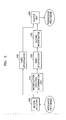
- FIG. 2 is a block diagram of an apparatus for converting an interlaced image into a progressive image according to an embodiment of the present invention.
- the apparatus includes motion detector 200, an interpolation direction determination unit 210, a first interpolator 220, a second interpolator 230, a third interpolator 240, and an output unit 250.
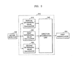
- FIG. 3 is a detailed block diagram of the interpolation direction determination unit 210 of FIG. 2.
- the interpolation direction determination unit 210 includes a vertical differential value calculator 310, a first differential value calculator 320, a second differential value calculator 330, and a direction determination unit 340.
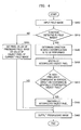
- FIG. 4 is a flowchart illustrating a method of converting an interlaced image into a progressive image according to an embodiment of the present invention.
- the motion detector 200 determines whether motion is detected in each pixel to be interpolated in the current field image (S41 0).
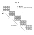
- FIG. 6 illustrates an arrangement of pixels explaining motion detection according to an embodiment of the present invention.
- FIG. 6 reveals that the difference between pixel values of preceding and following field images of the current field image is very small or zero. Thus, whether there is motion in the current field image can be determined using the pixel values of the preceding and following field images.
- the motion detector 200 computes a value M representing a change at an object pixel value using two preceding field images and two following field images, based on the following Equation (1). If the value M is less than a first threshold value T1 , the motion detector 200 determines that there is no motion at object pixel of the current field image.
- the motion detector 200 determines that there is motion at an object pixel of the current field image.
- M
- Equation (1) and FIG. 6 X denotes an object pixel of the current field image (n-th) that is to be interpolated, and a through x denote pixel values of the field images ((n-2)-th through (n+2)-th) as shown in FIG. 6.
- the third interpolator 240 interpolates the object pixel using a corresponding pixel of the preceding field image. That is, the third interpolator 240 sets the pixel value of the preceding field image as the value of the object pixel of the current field image (S415).
- the interpolation direction determination unit 210 determines a direction in which interpolation is to be performed (S420).
- FIG. 7 illustrates an arrangement of pixels explaining this method according to an embodiment of the present invention.
- the vertical differential value calculator 310 computes a vertical differential value vert using the following Equation (2) and outputs the vertical differential value vert to the direction determination unit 340, and the direction determination unit 340 compares the vertical differential value vert with a second threshold value T2 to determine whether interpolation is to be performed in a vertical direction (S521).
- vert
- the direction determination unit 340 determines as the vertical direction the direction in which interpolation is to be performed and outputs the result of determination to the first interpolator 220 (S523).
- the direction determination unit 340 receives a differential value in a first diagonal direction from the first differential value calculator 320, receives a differential value in a second diagonal direction from the second differential value calculator 330, and computes a bias value using the differential values and the following Equation (3) (S525).
- Bias
- denotes the differential value in the first diagonal direction, received from the first differential value calculator 320; and
- the direction determination unit 340 determines whether the bias value is larger than a third threshold value T3 (S527). When the bias value is less than or equal to the third threshold value T3 , the direction determination unit 340 determines that interpolation is to be performed in the vertical direction (S523). When the bias value is greater than the third threshold value T3 , the direction determination unit 340 determines that interpolation is to be performed in a diagonal direction (S529).
- the signs of weights given to the pixel values A, B , and C are opposite to those of weights given to the pixel values D , E , and F .
- the diagonal direction of the object pixel X is determined by multiplying these pixel values A, B, C, D, E, and F by given corresponding weights, respectively, summing the results of multiplication to generate a weighted sum, and determining the diagonal direction of the object pixel value X according to the weighted sum.
- the signs of the weights given to the values of the pixels along the scan line above the object pixel are opposite to the signs of the weights given to the values of the pixels along the scan line below the object pixel in order to minimize the weighted sum obtained when the value of a pixel in the scan line above the object pixel is similar to the value of a pixel in the scan line below the object pixel.
- the above method is for computing the differences between the pixel values. According to this method, although all possible cases where diagonal lines can appear in pixel groups are not considered, it is possible to precisely detect a diagonal line to which the object pixel belongs.
- the direction determination unit 340 uses the bias value computed using Equation (3) when determining a direction of a diagonal line to which the object pixel belongs, and determines a direction in which a differential value with a smallest absolute value is obtained as a diagonal direction when the bias value is larger than the third threshold value T3 . That is, when Bias > T3 and
- FIG. 7 is a diagram illustrating detecting of edges covering the values with the values A, B, E, and F in several directions at once. Accordingly, according to the present invention, it is possible to detect diagonal lines with less computational complexity while reducing artifacts caused by errors in the detection of diagonal lines, as compared to a conventional method.
- the first interpolator 220 receives from the interpolation direction determination unit 210 the result of determination regarding the direction in which interpolation is to be performed, and interpolates the value of the object pixel spatially in the determined direction using a predetermined spatial filter (S430).
- FIG. 8 illustrates an arrangement of pixels explaining spatial filtering performed in a determined direction in which interpolation is to be performed, using only information regarding a current field image, according to an embodiment of the present invention.
- the first interpolator 220 uses a 2-tap filter, which is a low-pass filter, when computing an interpolated value X ' of an object pixel X , which is to be interpolated, in a diagonal direction, and a 6-tap filter, which is a high-pass filter, when computing an interpolated value X ' of the object pixel X in a vertical direction.
- x >> y is understood to be a function that divides a value x by a value 2 y .
- the first interpolator 220 computes the interpolated value X ' using the Equation (4) with the 2-tap filter when the direction determined by the interpolation direction determination unit 210 is the first diagonal direction shown in FIG. 7, and computes the interpolated value X ' using Equation (5) with the 2-tap filter when the determined direction is the second diagonal direction shown in FIG. 7. If the determined direction is the vertical direction, the first interpolator 220 computes the interpolated value X ' using Equation (6) with the 6-tap filter.
- a high-pass filter is used to compute an interpolated value of an object pixel that is to be interpolated so as to preserve an edge of an image along a diagonal direction.
- the edge of an image in a diagonal direction is smoothed by canceling jaggies using the 2-tap filter which is a low-pass filter, and high-frequency components are preserved in the remaining portions of the image using the 6-tap filter which is a high-pass filter.
- the second interpolator 230 receives a value obtained by spatially interpolating the object pixel from the first interpolator 220, and compares the vertical differential value vert computed using Equation (2) with a fourth threshold value T4 so as to determine whether a high-frequency component in a vertical direction is present in the spatially interpolated object pixel (S440).
- the second interpolator 230 determines that the high-frequency component is present when the vertical differential value vert is equal to or greater than the fourth threshold value T4 , and determines the high-frequency component is not present otherwise.
- the high-frequency component in the vertical direction means that an edge of the image exists in a horizontal direction, and the difference of values of the corresponding pixels between the preceding field image and the current field image to be very large, thus causing flickering.
- the value X ' of the spatially interpolated object pixel must to be reset using time information.
- the second interpolator 230 resets the value X ' of the object pixel to a new value X " using the following Equation (7) (S450).
- X ′′ ( 10 ⁇ X ′ + 3 ⁇ h + 3 ⁇ k ) > > 4 wherein h and k denote pixel values of field images as shown in FIG. 6.
- Operations S410 through S450 are performed on all pixels of the current field image that must be interpolated so as to convert the current field image into a progressive image, and the output unit 250 outputs the progressive image (S460).
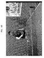
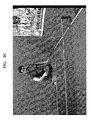
- FIGS. 9A through 9C Examples of a 720 ⁇ 240 interlaced image and a progressive image converted from the interlaced image are shown in FIGS. 9A through 9C, and FIGS. 10A through 10C.
- FIG. 9A illustrates an input interlaced image.
- FIG. 9B illustrates a progressive image converted from the interlaced image of FIG. 9A using an image conversion method according to an embodiment of the present invention.
- FIG. 9C illustrates a progressive image converted from the interlaced image using a conventional image conversion method.
- jaggies occur in the right arm and left shoulder of a person who is playing table tennis, but referring to FIG. 9B, the jaggies are lessened.
- a line of the edges of a ping-pong table looks unclear in FIG. 9C, but the line looks clearer in FIG. 9B.
- FIG. 10A illustrates another interlaced image.
- FIG. 10B illustrates a progressive image converted from the interlaced image of FIG. 10A using an image conversion method according to an embodiment of the present invention.
- FIG. 10C illustrates a progressive image converted from the interlaced image using a conventional image method. Referring to FIG. 10C, jaggies occur in characters included in the progressive image in a diagonal direction, but referring to FIG. 10B, the occurrence of the jaggies is lessened.
- the present invention can be embodied as computer readable code in a computer readable medium.
- the computer readable medium may be any recording apparatus capable of storing data that is read by a computer system, e.g., a read-only memory (ROM), a random access memory (RAM), a compact disc (CD)-ROM, a magnetic tape, a floppy disk, an optical data storage device, and so on.
- the computer readable medium may be a carrier wave that transmits data via the Internet, for example.
- the computer readable recording medium can be distributed among computer systems that are interconnected through a network, and the present invention may be stored and implemented as a computer readable code in the distributed system.
- an interlaced image is converted into a progressive image by interpolating pixels of the interlaced image with motion either in a vertical direction or in a diagonal direction and setting the values of the other pixels with no motion to the values of corresponding pixels of a previous field image. Accordingly, it is possible to convert an interlaced image into a progressive image adaptively to image motion while reducing damage to the original image.
- An image conversion apparatus and method according to the present invention are applicable to an image processing apparatus such as a digital television or a DVD player. If used in such an image processing apparatus, the occurrence of jaggies in a progressive image can be reduced and the definition of an image at a high frequency can be increased, thereby improving the quality of image.
Landscapes
- Engineering & Computer Science (AREA)
- Multimedia (AREA)
- Signal Processing (AREA)
- Computer Graphics (AREA)
- Television Systems (AREA)
Applications Claiming Priority (1)
| Application Number | Priority Date | Filing Date | Title |
|---|---|---|---|
| US60446304P | 2004-08-26 | 2004-08-26 |
Publications (2)
| Publication Number | Publication Date |
|---|---|
| EP1631068A2 true EP1631068A2 (de) | 2006-03-01 |
| EP1631068A3 EP1631068A3 (de) | 2008-09-03 |
Family
ID=35431323
Family Applications (1)
| Application Number | Title | Priority Date | Filing Date |
|---|---|---|---|
| EP04255997A Withdrawn EP1631068A3 (de) | 2004-08-26 | 2004-09-29 | Vorrichtung und Verfahren zur Umwandlung von Zeilensprungbildern zu progressiven Bildern |
Country Status (4)
| Country | Link |
|---|---|
| US (1) | US7808553B2 (de) |
| EP (1) | EP1631068A3 (de) |
| JP (1) | JP2006067541A (de) |
| CN (1) | CN1741604A (de) |
Cited By (1)
| Publication number | Priority date | Publication date | Assignee | Title |
|---|---|---|---|---|
| EP2114068A1 (de) * | 2008-04-30 | 2009-11-04 | Sony Corporation | Verfahren zum Umwandeln eines Bildes und Bildumwandlungseinheit |
Families Citing this family (12)
| Publication number | Priority date | Publication date | Assignee | Title |
|---|---|---|---|---|
| US7587091B2 (en) * | 2004-10-29 | 2009-09-08 | Intel Corporation | De-interlacing using decoder parameters |
| US8325273B2 (en) * | 2005-06-06 | 2012-12-04 | Broadcom Corporation | System and method for vertical gradient detection in video processing |
| DE102005063072B4 (de) * | 2005-12-30 | 2017-02-02 | Entropic Communications, Inc. | Verfahren und Vorrichtung zur Zwischenzeileninterpolation |
| JP4863767B2 (ja) * | 2006-05-22 | 2012-01-25 | ソニー株式会社 | 映像信号処理装置及び画像表示装置 |
| JP2008011389A (ja) * | 2006-06-30 | 2008-01-17 | Toshiba Corp | 映像信号スケーリング装置 |
| TWI347130B (en) * | 2006-08-29 | 2011-08-11 | Realtek Semiconductor Corp | Method and apparatus for de-interlacing video data through utilizing horizontal motion estimation and horizontal motion compensation |
| KR101354659B1 (ko) * | 2006-11-08 | 2014-01-28 | 삼성전자주식회사 | 멀티 코덱을 지원하는 움직임 보상 방법 및 장치 |
| US20090046202A1 (en) * | 2007-08-17 | 2009-02-19 | Himax Technologies Limited | De-interlace method and apparatus |
| US8593572B2 (en) * | 2008-01-30 | 2013-11-26 | Csr Technology Inc. | Video signal motion detection |
| US9129409B2 (en) * | 2009-07-29 | 2015-09-08 | Qualcomm Incorporated | System and method of compressing video content |
| GB2494065B (en) * | 2010-06-07 | 2016-06-08 | Zoran (France) | Image interpolation method with decision mixing |
| US8917354B2 (en) * | 2013-09-30 | 2014-12-23 | Amlogic Co., Ltd. | Motion detection in video fields |
Family Cites Families (33)
| Publication number | Priority date | Publication date | Assignee | Title |
|---|---|---|---|---|
| US5081532A (en) * | 1990-08-30 | 1992-01-14 | Zenith Electronics Corporation | Adaptive progressive scan converter |
| US6097847A (en) * | 1993-05-31 | 2000-08-01 | Nec Corporation | Method of and apparatus for calculating sharpness of image and apparatus for sharpening image |
| JPH07131761A (ja) * | 1993-10-29 | 1995-05-19 | Toshiba Corp | テレビジョン信号処理回路 |
| US5886745A (en) * | 1994-12-09 | 1999-03-23 | Matsushita Electric Industrial Co., Ltd. | Progressive scanning conversion apparatus |
| JPH08317336A (ja) * | 1995-03-15 | 1996-11-29 | Fuji Photo Film Co Ltd | 補間画像データ生成装置および方法 |
| US5661525A (en) * | 1995-03-27 | 1997-08-26 | Lucent Technologies Inc. | Method and apparatus for converting an interlaced video frame sequence into a progressively-scanned sequence |
| EP1307056B1 (de) * | 1995-06-30 | 2004-10-06 | Mitsubishi Denki Kabushiki Kaisha | Einrichtung zur Abtastumsetzung mit verbesserter vertikaler Auflösung und Vorrichtung zur Flimmerreduzierung |
| US5532751A (en) | 1995-07-31 | 1996-07-02 | Lui; Sam | Edge-based interlaced to progressive video conversion system |
| US5936676A (en) * | 1997-08-21 | 1999-08-10 | Miranda Technologies Inc. | Apparatus and method for line interpolating an interlaced video signal |
| FR2766946B1 (fr) * | 1997-08-04 | 2000-08-11 | Thomson Multimedia Sa | Procede et dispositif de pretraitement pour estimation de mouvement |
| US6122017A (en) * | 1998-01-22 | 2000-09-19 | Hewlett-Packard Company | Method for providing motion-compensated multi-field enhancement of still images from video |
| US6181382B1 (en) * | 1998-04-03 | 2001-01-30 | Miranda Technologies Inc. | HDTV up converter |
| KR100731523B1 (ko) * | 1999-05-25 | 2007-06-25 | 코닌클리케 필립스 일렉트로닉스 엔.브이. | 인터레이싱된 영상 신호의 프로그레시브 스캐닝된 영상 신호로의 변환 |
| US6630961B1 (en) * | 1999-06-30 | 2003-10-07 | Lg Electronics Inc. | Deinterlacing device and method |
| US6421090B1 (en) * | 1999-08-27 | 2002-07-16 | Trident Microsystems, Inc. | Motion and edge adaptive deinterlacing |
| WO2001080559A2 (en) * | 2000-04-18 | 2001-10-25 | Silicon Image | Method, system and apparatus for identifying the source type and quality level of a video sequence |
| JP4150947B2 (ja) * | 2000-08-23 | 2008-09-17 | ソニー株式会社 | 画像処理装置および方法、並びに記録媒体 |
| US7116372B2 (en) * | 2000-10-20 | 2006-10-03 | Matsushita Electric Industrial Co., Ltd. | Method and apparatus for deinterlacing |
| JP4553481B2 (ja) * | 2000-12-14 | 2010-09-29 | パナソニック株式会社 | 走査線補間装置 |
| US6940557B2 (en) * | 2001-02-08 | 2005-09-06 | Micronas Semiconductors, Inc. | Adaptive interlace-to-progressive scan conversion algorithm |
| US6931062B2 (en) * | 2001-04-11 | 2005-08-16 | Koninklijke Philips Electronics N.V. | Decoding system and method for proper interpolation for motion compensation |
| US6813359B2 (en) * | 2001-05-01 | 2004-11-02 | Bae Systems Information And Electronic Systems Integration Inc. | Apparatus and method for minimizing multipath interference |
| KR100393066B1 (ko) * | 2001-06-11 | 2003-07-31 | 삼성전자주식회사 | 적응 움직임 보상형 디-인터레이싱 장치 및 그 방법 |
| EP1442426A2 (de) * | 2001-11-01 | 2004-08-04 | Koninklijke Philips Electronics N.V. | Verbesserte räumliche auflösung von videobildern |
| US7269220B2 (en) * | 2002-07-16 | 2007-09-11 | Broadcom Corporation | Adaptive motion detection and control |
| KR20040009967A (ko) * | 2002-07-26 | 2004-01-31 | 삼성전자주식회사 | 디인터레이싱장치 및 방법 |
| KR20040050577A (ko) * | 2002-12-10 | 2004-06-16 | 삼성전자주식회사 | 디인터레이싱 장치 및 방법 |
| US7242819B2 (en) * | 2002-12-13 | 2007-07-10 | Trident Microsystems, Inc. | Method and system for advanced edge-adaptive interpolation for interlace-to-progressive conversion |
| JP4220284B2 (ja) * | 2003-03-28 | 2009-02-04 | 株式会社東芝 | フレーム補間方法、装置及びこれを用いた画像表示システム |
| JP3887346B2 (ja) * | 2003-04-28 | 2007-02-28 | 株式会社東芝 | 映像信号処理装置及び映像信号処理方法、映像表示装置 |
| KR100979811B1 (ko) * | 2003-08-12 | 2010-09-02 | 삼성전자주식회사 | 수평 방향 에지의 패턴을 고려한 순차주사화 장치 및 방법 |
| KR100568105B1 (ko) * | 2003-10-02 | 2006-04-05 | 삼성전자주식회사 | 에지 기반의 영상 적응형 디인터레이싱 방법 |
| US7170561B2 (en) * | 2003-12-04 | 2007-01-30 | Lsi Logic Corporation | Method and apparatus for video and image deinterlacing and format conversion |
-
2004
- 2004-09-29 EP EP04255997A patent/EP1631068A3/de not_active Withdrawn
- 2004-10-12 US US10/961,478 patent/US7808553B2/en not_active Expired - Fee Related
- 2004-11-04 JP JP2004320068A patent/JP2006067541A/ja not_active Withdrawn
- 2004-11-23 CN CN200410095053.2A patent/CN1741604A/zh active Pending
Cited By (3)
| Publication number | Priority date | Publication date | Assignee | Title |
|---|---|---|---|---|
| EP2114068A1 (de) * | 2008-04-30 | 2009-11-04 | Sony Corporation | Verfahren zum Umwandeln eines Bildes und Bildumwandlungseinheit |
| CN101577805B (zh) * | 2008-04-30 | 2011-05-25 | 索尼株式会社 | 用于转换图像的方法和图像转换单元 |
| US8174615B2 (en) | 2008-04-30 | 2012-05-08 | Sony Corporation | Method for converting an image and image conversion unit |
Also Published As
| Publication number | Publication date |
|---|---|
| CN1741604A (zh) | 2006-03-01 |
| US7808553B2 (en) | 2010-10-05 |
| EP1631068A3 (de) | 2008-09-03 |
| JP2006067541A (ja) | 2006-03-09 |
| US20070229534A1 (en) | 2007-10-04 |
Similar Documents
| Publication | Publication Date | Title |
|---|---|---|
| US7406208B2 (en) | Edge enhancement process and system | |
| JP5839631B2 (ja) | ブロックノイズの検出方法 | |
| JP4631966B2 (ja) | 画像処理装置、および画像処理方法、並びにプログラム | |
| US7265791B2 (en) | Method and apparatus for de-interlacing video signal | |
| US5111511A (en) | Image motion vector detecting apparatus | |
| US8189105B2 (en) | Systems and methods of motion and edge adaptive processing including motion compensation features | |
| EP2164040B1 (de) | System und Verfahren zur Vergrößerung von hochqualitativen Bildern und Video | |
| EP0739129A2 (de) | System und Verfahren zum Herstellen von Standbildern hoher Qualität mittels Videobildern nach dem Zeilensprungverfahren | |
| US8358878B2 (en) | Method and apparatus for interpolating an image | |
| EP1631068A2 (de) | Vorrichtung und Verfahren zur Umwandlung von Zeilensprungbildern zu progressiven Bildern | |
| JP2011199716A (ja) | 画像処理装置、および画像処理方法、並びにプログラム | |
| US8208748B2 (en) | Apparatus and method for image interpolation based on low pass filtering | |
| EP2107521A2 (de) | Erfassung eines Randbereichs in einem Bild | |
| US7697790B2 (en) | Apparatus and method for enhancing quality of reproduced image | |
| CN102918830B (zh) | 图像处理装置和方法、图像显示装置和方法 | |
| US8213736B2 (en) | Image processing device and image processing method | |
| US8345163B2 (en) | Image processing device and method and image display device | |
| KR100874380B1 (ko) | 변형된 소벨 연산자를 이용한 디인터레이싱 장치 및 방법, 그리고 기록매체 | |
| EP1836678B1 (de) | Bildverarbeitung | |
| KR100552685B1 (ko) | 비월주사 영상을 순차 영상으로 변환하는 방법 및 장치 | |
| JP4250807B2 (ja) | フィールド周波数変換装置および変換方法 | |
| JP3832924B2 (ja) | 画像信号処理方法、画像信号処理装置及びコンピュータ読み取り可能な記録媒体 | |
| JP2004221960A (ja) | 動き検出装置およびノイズ低減装置 |
Legal Events
| Date | Code | Title | Description |
|---|---|---|---|
| PUAI | Public reference made under article 153(3) epc to a published international application that has entered the european phase |
Free format text: ORIGINAL CODE: 0009012 |
|
| AK | Designated contracting states |
Kind code of ref document: A2 Designated state(s): AT BE BG CH CY CZ DE DK EE ES FI FR GB GR HU IE IT LI LU MC NL PL PT RO SE SI SK TR |
|
| AX | Request for extension of the european patent |
Extension state: AL HR LT LV MK |
|
| PUAL | Search report despatched |
Free format text: ORIGINAL CODE: 0009013 |
|
| AK | Designated contracting states |
Kind code of ref document: A3 Designated state(s): AT BE BG CH CY CZ DE DK EE ES FI FR GB GR HU IE IT LI LU MC NL PL PT RO SE SI SK TR |
|
| AX | Request for extension of the european patent |
Extension state: AL HR LT LV MK |
|
| AKX | Designation fees paid | ||
| REG | Reference to a national code |
Ref country code: DE Ref legal event code: 8566 |
|
| STAA | Information on the status of an ep patent application or granted ep patent |
Free format text: STATUS: THE APPLICATION IS DEEMED TO BE WITHDRAWN |
|
| 18D | Application deemed to be withdrawn |
Effective date: 20090304 |