EP1630934A2 - Bürstenhalteranordnung für einen Fahrzeuggenerator - Google Patents
Bürstenhalteranordnung für einen Fahrzeuggenerator Download PDFInfo
- Publication number
- EP1630934A2 EP1630934A2 EP04029337A EP04029337A EP1630934A2 EP 1630934 A2 EP1630934 A2 EP 1630934A2 EP 04029337 A EP04029337 A EP 04029337A EP 04029337 A EP04029337 A EP 04029337A EP 1630934 A2 EP1630934 A2 EP 1630934A2
- Authority
- EP
- European Patent Office
- Prior art keywords
- brush
- brush holder
- lead lines
- metallic plate
- alternator
- Prior art date
- Legal status (The legal status is an assumption and is not a legal conclusion. Google has not performed a legal analysis and makes no representation as to the accuracy of the status listed.)
- Granted
Links
Images



Classifications
-
- H—ELECTRICITY
- H01—ELECTRIC ELEMENTS
- H01R—ELECTRICALLY-CONDUCTIVE CONNECTIONS; STRUCTURAL ASSOCIATIONS OF A PLURALITY OF MUTUALLY-INSULATED ELECTRICAL CONNECTING ELEMENTS; COUPLING DEVICES; CURRENT COLLECTORS
- H01R13/00—Details of coupling devices of the kinds covered by groups H01R12/70 or H01R24/00 - H01R33/00
- H01R13/46—Bases; Cases
- H01R13/52—Dustproof, splashproof, drip-proof, waterproof, or flameproof cases
- H01R13/5216—Dustproof, splashproof, drip-proof, waterproof, or flameproof cases characterised by the sealing material, e.g. gels or resins
-
- G—PHYSICS
- G01—MEASURING; TESTING
- G01N—INVESTIGATING OR ANALYSING MATERIALS BY DETERMINING THEIR CHEMICAL OR PHYSICAL PROPERTIES
- G01N33/00—Investigating or analysing materials by specific methods not covered by groups G01N1/00 - G01N31/00
- G01N33/0078—Testing material properties on manufactured objects
- G01N33/0083—Vehicle parts
-
- H—ELECTRICITY
- H01—ELECTRIC ELEMENTS
- H01R—ELECTRICALLY-CONDUCTIVE CONNECTIONS; STRUCTURAL ASSOCIATIONS OF A PLURALITY OF MUTUALLY-INSULATED ELECTRICAL CONNECTING ELEMENTS; COUPLING DEVICES; CURRENT COLLECTORS
- H01R39/00—Rotary current collectors, distributors or interrupters
- H01R39/02—Details for dynamo electric machines
- H01R39/38—Brush holders
-
- H—ELECTRICITY
- H02—GENERATION; CONVERSION OR DISTRIBUTION OF ELECTRIC POWER
- H02K—DYNAMO-ELECTRIC MACHINES
- H02K5/00—Casings; Enclosures; Supports
- H02K5/04—Casings or enclosures characterised by the shape, form or construction thereof
- H02K5/14—Means for supporting or protecting brushes or brush holders
- H02K5/141—Means for supporting or protecting brushes or brush holders for cooperation with slip-rings
-
- H—ELECTRICITY
- H02—GENERATION; CONVERSION OR DISTRIBUTION OF ELECTRIC POWER
- H02K—DYNAMO-ELECTRIC MACHINES
- H02K5/00—Casings; Enclosures; Supports
- H02K5/04—Casings or enclosures characterised by the shape, form or construction thereof
- H02K5/22—Auxiliary parts of casings not covered by groups H02K5/06-H02K5/20, e.g. shaped to form connection boxes or terminal boxes
- H02K5/225—Terminal boxes or connection arrangements
Definitions
- the present invention relates to a brush holder assembly of an alternator for a vehicle, and in particular to, a brush holder assembly of an alternator for a vehicle, in which the structure of a brush connecting rod extended from an end of a brush is modified to be connected with a terminal piece and sealed, thereby improving the assembling workability and largely enhancing the sealing performance.
- an alternator for a vehicle includes a casing 30 formed of a rear bracket 10 and a front bracket 20 respectively having shaft support parts 11 and 21, a shaft 60 installed in the interior of the casing and fixed with a pulley 40 at one end, a rotor 70 fixed at the shaft, a fan 71 fixed at both sides of the rotor, a stator 50 fixed at an inner wall of the casing, a slip ring 72 fixed at the other end of the shaft to be electrically connected with the rotor 70, a pair of brushes 81 operatively contacting with the slip ring, a brush holder assembly 80 that receives the brushes therein, a rectifier assembly 90 electrically connected with the stator, a heat sink 91 mounted on the brush holder assembly, and a regulator 92 adapted to adjust the magnitude of an AC voltage generated in the stator in a state that it contacts the heat sink.
- the brush holder assembly is formed of the brush holder 82.
- the brush holder 82 includes a brush box 83 into which the brushes 81 are inserted, a slip ring insertion part 84 into which the slip ring 72 is inserted, and a connecting part 85 connected with a cable.
- the brushes 81 are inserted in the brush box 83, wherein lower ends of the brushes contact the surface of the slip ring 72 in the slip ring insertion part 84, and upper ends of the brushes respectively include a lead line 81 a fitted with a spring 81 b thereon.
- the lead lines 81 a are extended upwardly and are connected with electrode pieces 86 insert injection-molded at the holder 82.
- the metal connection pieces 87 respectively include a lead line hole 87a through which a corresponding one of the lead lines 81 a passes, a soldering connection part 87b bent from the hole, and an electrode piece hole 87a into which a corresponding one of the electrode pieces 86 is inserted.
- the conventional brush holder assembly has disadvantages that the two metal connection pieces 87 should be used for each of the brushes individually, and the electrode pieces 86 should be precisely inserted into the electrode pieces 87c, which are very small-sized. Therefore, the assembling process becomes much complicated and, accordingly, the workability becomes significantly decreased.
- the conventional brush holder assembly still has a disadvantage that the rubber lid 88 should be separately designed depending on the size of the brush box 83. Therefore, the sealing property decreases.
- a brush holder assembly of an alternator for a vehicle that comprises a brush holder that includes a circular slip ring insertion part, a brush box connected on the slip ring insertion part and having a pair of brush insertion holes and electrode pieces inside, and a connection part connected at one side of the brush box; a pair of brushes that are inserted into the brush box of the brush holder, and provided with lead lines at rear ends, wherein the lead lines are provided with compression rings; a non-metallic plate having lead line holes and grommets provided to the lead line holes, wherein the non-metallic plate induces the lead lines of the brushes into the insulation state with respect to the electrode pieces provided at a side of the brush box; a silicon member adapted to sealingly cover an upper side of the non-metallic plate for blocking the brush insertion holes of the brush box; and a cover for covering an upper side of the non-metallic plate to be fixed at the brush box.
- the grommets are formed in the horn shape of which a lower side is wide, and an upper side is narrow, so that the lead lines can be easily inserted and lifted.
- Figure 4 is a perspective view illustrating the construction of a brush holder according to the present invention
- Figure 5 is a front cross sectional view illustrating the construction of a brush holder according to the present invention
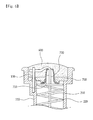
- Figure 6 is an enlarged cross sectional view illustrating principal parts of the brush holder according to the present invention
- Figure 7 is a disassembled perspective view illustrating principal parts of the brush holder according to the present invention.
- a brush holder 100 includes a circular slip ring insertion part 140, a brush box 110 connected on the circular slip ring insertion part 140 and having a pair of brush insertion holes 150 and electrode pieces 130 inside, and a connection part 120 connected with one side of the brush box 110.
- a pair of brushes 200 is inserted into the brush box 110 of the brush holder 100, and lead lines 210 at rear ends of the brushes are provided with compression springs in the same manner as the conventional art.
- a non-metallic plate 700 is provided on the brush insertion holes 150, and the lead lines 210 of the brushes are arranged in an insulation state with respect to the electrode pieces 130 provided at one side of the brush box 110.
- the non-metallic plate 700 includes lead line holes 710 for passing the lead lines 210, and grommets 720 provided at the lead line holes.
- the grommets 720 are formed in the horn shape of which an upper side is narrow, and a lower side is wide, so that the lead lines 210 are easily inserted and lifted but not to be escaped from the lead line holes downwardly.
- ends of the lead lines 210 are welded to the electrode pieces 130 after being inserted and lifted via the grommets upwardly.
- silicon 600 is covered on top of the non-metallic plate 700 and is cured after the lead lines 210 are soldered.
- a cover 500 covers the top part of the non-metallic plate 700 and is fixed at the brush box 110, thereby finishing the assembling process.
- the brush holder assembly comprises a brush holder 100, a pair of brushes 200 having a spring 220 respectively, a non-metallic plate 700, a silicon member 600 supplied by spraying silicon, and a cover 500, wherein the assembling process of the non-metallic plate 700 and the spraying method of the silicon are newly provided in the present invention.
- both the brush insertion holes can be commonly blocked by using a single non-metallic plate instead of using two metallic connection pieces separately, so that the assembling work and lead line soldering process are simplified.
- the silicon is supplied and cured on the non-metallic plate, so that it is possible to achieve very tight sealing and to perfectly prevent the penetration of moisture and foreign substances.
Landscapes
- Chemical & Material Sciences (AREA)
- Engineering & Computer Science (AREA)
- Power Engineering (AREA)
- Health & Medical Sciences (AREA)
- Life Sciences & Earth Sciences (AREA)
- Dispersion Chemistry (AREA)
- Biochemistry (AREA)
- Analytical Chemistry (AREA)
- Physics & Mathematics (AREA)
- General Health & Medical Sciences (AREA)
- General Physics & Mathematics (AREA)
- Immunology (AREA)
- Pathology (AREA)
- Medicinal Chemistry (AREA)
- Food Science & Technology (AREA)
- Motor Or Generator Current Collectors (AREA)
- Motor Or Generator Frames (AREA)
- Synchronous Machinery (AREA)
Applications Claiming Priority (1)
| Application Number | Priority Date | Filing Date | Title |
|---|---|---|---|
| KR1020040069043A KR100605380B1 (ko) | 2004-08-31 | 2004-08-31 | 자동차용 발전기의 브러시 홀더 어셈블리 |
Publications (3)
| Publication Number | Publication Date |
|---|---|
| EP1630934A2 true EP1630934A2 (de) | 2006-03-01 |
| EP1630934A3 EP1630934A3 (de) | 2006-08-16 |
| EP1630934B1 EP1630934B1 (de) | 2010-04-28 |
Family
ID=36139670
Family Applications (1)
| Application Number | Title | Priority Date | Filing Date |
|---|---|---|---|
| EP04029337A Ceased EP1630934B1 (de) | 2004-08-31 | 2004-12-10 | Bürstenhalteranordnung für einen Fahrzeuggenerator |
Country Status (5)
| Country | Link |
|---|---|
| EP (1) | EP1630934B1 (de) |
| JP (1) | JP2006074982A (de) |
| KR (1) | KR100605380B1 (de) |
| CN (1) | CN1744408A (de) |
| DE (1) | DE602004026861D1 (de) |
Cited By (2)
| Publication number | Priority date | Publication date | Assignee | Title |
|---|---|---|---|---|
| WO2010093617A3 (en) * | 2009-02-13 | 2010-12-02 | Remy Technologies, L.L.C. | Brush holder assembly for a dynamo-electric machine |
| EP3799268A1 (de) * | 2019-09-26 | 2021-03-31 | Mahle International GmbH | Anordnung für eine rotierende elektrische maschine |
Families Citing this family (4)
| Publication number | Priority date | Publication date | Assignee | Title |
|---|---|---|---|---|
| KR101144906B1 (ko) | 2010-11-05 | 2012-05-14 | 발레오전장시스템스코리아 주식회사 | 스타트 모터의 그로밋 조립체 |
| CN103659129B (zh) * | 2012-09-18 | 2016-08-24 | 株式会社大亨 | 转动换位器 |
| KR200486478Y1 (ko) | 2017-03-16 | 2018-05-24 | 발레오전장시스템스코리아 주식회사 | 차량용 발전기의 브러시 홀더 및 이를 포함하는 레귤레이터 |
| CN108023430A (zh) * | 2017-12-28 | 2018-05-11 | 索恩格汽车部件(中国)有限公司 | 用于汽车交流发电机碳刷系统的保护盖、交流发电机和汽车 |
Family Cites Families (6)
| Publication number | Priority date | Publication date | Assignee | Title |
|---|---|---|---|---|
| US2798176A (en) * | 1954-12-07 | 1957-07-02 | Scovill Manufacturing Co | Brush holder for electric motors |
| DE8409001U1 (de) * | 1984-03-23 | 1985-06-20 | Robert Bosch Gmbh, 7000 Stuttgart | Wechsel-, insbesondere Drehstrom-Generator für Fahrzeuge |
| KR950022277U (ko) * | 1993-12-29 | 1995-07-28 | 배선정리구를 고정시킬 수 있는 고정홀을 갖는 패널구조 | |
| JP2002238225A (ja) * | 2001-02-06 | 2002-08-23 | Mitsubishi Electric Corp | 交流発電機 |
| JP3519706B2 (ja) * | 2001-07-18 | 2004-04-19 | 東京パーツ工業株式会社 | ブラシ制振装置とこのブラシ制振装置の製造方法及びこのブラシ制振装置を備えた扁平型振動モータ |
| KR100426238B1 (ko) * | 2002-05-29 | 2004-04-08 | 발레오만도전장시스템스코리아 주식회사 | 발전기의 브러시홀더 밀폐구조 |
-
2004
- 2004-08-31 KR KR1020040069043A patent/KR100605380B1/ko not_active Expired - Fee Related
- 2004-12-10 JP JP2004358635A patent/JP2006074982A/ja active Pending
- 2004-12-10 EP EP04029337A patent/EP1630934B1/de not_active Ceased
- 2004-12-10 DE DE602004026861T patent/DE602004026861D1/de not_active Expired - Lifetime
-
2005
- 2005-01-19 CN CNA2005100055787A patent/CN1744408A/zh active Pending
Cited By (2)
| Publication number | Priority date | Publication date | Assignee | Title |
|---|---|---|---|---|
| WO2010093617A3 (en) * | 2009-02-13 | 2010-12-02 | Remy Technologies, L.L.C. | Brush holder assembly for a dynamo-electric machine |
| EP3799268A1 (de) * | 2019-09-26 | 2021-03-31 | Mahle International GmbH | Anordnung für eine rotierende elektrische maschine |
Also Published As
| Publication number | Publication date |
|---|---|
| JP2006074982A (ja) | 2006-03-16 |
| CN1744408A (zh) | 2006-03-08 |
| EP1630934A3 (de) | 2006-08-16 |
| KR100605380B1 (ko) | 2006-08-02 |
| KR20060020241A (ko) | 2006-03-06 |
| EP1630934B1 (de) | 2010-04-28 |
| DE602004026861D1 (de) | 2010-06-10 |
Similar Documents
| Publication | Publication Date | Title |
|---|---|---|
| US8378538B2 (en) | DC motor with a leadthrough capacitor | |
| US20110095630A1 (en) | End cap assembly | |
| US8861225B2 (en) | Capacitor mounting construction | |
| EP1814211A2 (de) | Rauschunterdrückungsstruktur eines Gebläsemotors | |
| US5245241A (en) | Brush holder in ac generator for vehicles | |
| JPH05122881A (ja) | 小型モータ | |
| CN108781019A (zh) | 电机和用于制造电机的方法 | |
| CN1386074A (zh) | 电磁诱导型传动装置及其安装构造以及便携式情报机器 | |
| EP1630934A2 (de) | Bürstenhalteranordnung für einen Fahrzeuggenerator | |
| CN207117348U (zh) | 具有防电腐蚀结构的塑封电机 | |
| CN101317315A (zh) | 带有接地接触板的刷架组件 | |
| CN104104192B (zh) | 用于机动车的电驱动器 | |
| US6961437B2 (en) | Capacitor microphone | |
| US10868458B2 (en) | Brush-holder regulator for motor vehicle alternator | |
| CN108028499B (zh) | 屏蔽连接器 | |
| EP1496599B1 (de) | Wechselstromgenerator für ein fahrzeug | |
| GB2173648A (en) | Electric motors and their assembly | |
| KR101222674B1 (ko) | 팬 모터용 브러시 홀더 장치 | |
| JP2003097436A (ja) | 電動コンプレッサ | |
| US20030007297A1 (en) | Train relief component having an intergrated capacitor | |
| GB2172754A (en) | Electric motor | |
| CN204669140U (zh) | 接线盒以及具有该接线盒的电机 | |
| KR100574331B1 (ko) | 스테이터 인출선용 절연부재를 갖는 알터네이터 | |
| CN211656139U (zh) | Sim卡安装结构及车载显示屏组件 | |
| WO2005077017A2 (en) | Improved brush card apparatus and method |
Legal Events
| Date | Code | Title | Description |
|---|---|---|---|
| PUAI | Public reference made under article 153(3) epc to a published international application that has entered the european phase |
Free format text: ORIGINAL CODE: 0009012 |
|
| AK | Designated contracting states |
Kind code of ref document: A2 Designated state(s): AT BE BG CH CY CZ DE DK EE ES FI FR GB GR HU IE IS IT LI LT LU MC NL PL PT RO SE SI SK TR |
|
| AX | Request for extension of the european patent |
Extension state: AL BA HR LV MK YU |
|
| PUAL | Search report despatched |
Free format text: ORIGINAL CODE: 0009013 |
|
| RIC1 | Information provided on ipc code assigned before grant |
Ipc: H02K 13/00 20060101AFI20051107BHEP Ipc: H01R 39/41 20060101ALI20060630BHEP Ipc: H02K 5/14 20060101ALI20060630BHEP |
|
| AK | Designated contracting states |
Kind code of ref document: A3 Designated state(s): AT BE BG CH CY CZ DE DK EE ES FI FR GB GR HU IE IS IT LI LT LU MC NL PL PT RO SE SI SK TR |
|
| AX | Request for extension of the european patent |
Extension state: AL BA HR LV MK YU |
|
| 17P | Request for examination filed |
Effective date: 20060905 |
|
| AKX | Designation fees paid |
Designated state(s): DE FR GB IT TR |
|
| 17Q | First examination report despatched |
Effective date: 20070903 |
|
| GRAP | Despatch of communication of intention to grant a patent |
Free format text: ORIGINAL CODE: EPIDOSNIGR1 |
|
| GRAS | Grant fee paid |
Free format text: ORIGINAL CODE: EPIDOSNIGR3 |
|
| GRAA | (expected) grant |
Free format text: ORIGINAL CODE: 0009210 |
|
| AK | Designated contracting states |
Kind code of ref document: B1 Designated state(s): DE FR GB IT TR |
|
| REG | Reference to a national code |
Ref country code: GB Ref legal event code: FG4D |
|
| REF | Corresponds to: |
Ref document number: 602004026861 Country of ref document: DE Date of ref document: 20100610 Kind code of ref document: P |
|
| PLBE | No opposition filed within time limit |
Free format text: ORIGINAL CODE: 0009261 |
|
| STAA | Information on the status of an ep patent application or granted ep patent |
Free format text: STATUS: NO OPPOSITION FILED WITHIN TIME LIMIT |
|
| PG25 | Lapsed in a contracting state [announced via postgrant information from national office to epo] |
Ref country code: IT Free format text: LAPSE BECAUSE OF FAILURE TO SUBMIT A TRANSLATION OF THE DESCRIPTION OR TO PAY THE FEE WITHIN THE PRESCRIBED TIME-LIMIT Effective date: 20100428 |
|
| 26N | No opposition filed |
Effective date: 20110131 |
|
| REG | Reference to a national code |
Ref country code: FR Ref legal event code: PLFP Year of fee payment: 12 |
|
| REG | Reference to a national code |
Ref country code: FR Ref legal event code: PLFP Year of fee payment: 13 |
|
| REG | Reference to a national code |
Ref country code: FR Ref legal event code: PLFP Year of fee payment: 14 |
|
| PGFP | Annual fee paid to national office [announced via postgrant information from national office to epo] |
Ref country code: TR Payment date: 20201130 Year of fee payment: 17 |
|
| PGFP | Annual fee paid to national office [announced via postgrant information from national office to epo] |
Ref country code: FR Payment date: 20201209 Year of fee payment: 17 Ref country code: DE Payment date: 20201207 Year of fee payment: 17 Ref country code: GB Payment date: 20201209 Year of fee payment: 17 |
|
| REG | Reference to a national code |
Ref country code: DE Ref legal event code: R119 Ref document number: 602004026861 Country of ref document: DE |
|
| GBPC | Gb: european patent ceased through non-payment of renewal fee |
Effective date: 20211210 |
|
| PG25 | Lapsed in a contracting state [announced via postgrant information from national office to epo] |
Ref country code: GB Free format text: LAPSE BECAUSE OF NON-PAYMENT OF DUE FEES Effective date: 20211210 Ref country code: DE Free format text: LAPSE BECAUSE OF NON-PAYMENT OF DUE FEES Effective date: 20220701 |
|
| PG25 | Lapsed in a contracting state [announced via postgrant information from national office to epo] |
Ref country code: FR Free format text: LAPSE BECAUSE OF NON-PAYMENT OF DUE FEES Effective date: 20211231 |
|
| PG25 | Lapsed in a contracting state [announced via postgrant information from national office to epo] |
Ref country code: TR Free format text: LAPSE BECAUSE OF NON-PAYMENT OF DUE FEES Effective date: 20211210 |