EP1630451A2 - Courroie de transmission avec revètement extérieur en matériau textile stabilisé à mailles ouvertes pour une pénétration améliorée du caoutchouc - Google Patents
Courroie de transmission avec revètement extérieur en matériau textile stabilisé à mailles ouvertes pour une pénétration améliorée du caoutchouc Download PDFInfo
- Publication number
- EP1630451A2 EP1630451A2 EP05077626A EP05077626A EP1630451A2 EP 1630451 A2 EP1630451 A2 EP 1630451A2 EP 05077626 A EP05077626 A EP 05077626A EP 05077626 A EP05077626 A EP 05077626A EP 1630451 A2 EP1630451 A2 EP 1630451A2
- Authority
- EP
- European Patent Office
- Prior art keywords
- belt
- textile material
- power transmission
- rubber
- transmission belt
- Prior art date
- Legal status (The legal status is an assumption and is not a legal conclusion. Google has not performed a legal analysis and makes no representation as to the accuracy of the status listed.)
- Withdrawn
Links
Images

Classifications
-
- B—PERFORMING OPERATIONS; TRANSPORTING
- B29—WORKING OF PLASTICS; WORKING OF SUBSTANCES IN A PLASTIC STATE IN GENERAL
- B29D—PRODUCING PARTICULAR ARTICLES FROM PLASTICS OR FROM SUBSTANCES IN A PLASTIC STATE
- B29D29/00—Producing belts or bands
- B29D29/08—Toothed driving belts
-
- F—MECHANICAL ENGINEERING; LIGHTING; HEATING; WEAPONS; BLASTING
- F16—ENGINEERING ELEMENTS AND UNITS; GENERAL MEASURES FOR PRODUCING AND MAINTAINING EFFECTIVE FUNCTIONING OF MACHINES OR INSTALLATIONS; THERMAL INSULATION IN GENERAL
- F16G—BELTS, CABLES, OR ROPES, PREDOMINANTLY USED FOR DRIVING PURPOSES; CHAINS; FITTINGS PREDOMINANTLY USED THEREFOR
- F16G1/00—Driving-belts
- F16G1/28—Driving-belts with a contact surface of special shape, e.g. toothed
-
- F—MECHANICAL ENGINEERING; LIGHTING; HEATING; WEAPONS; BLASTING
- F16—ENGINEERING ELEMENTS AND UNITS; GENERAL MEASURES FOR PRODUCING AND MAINTAINING EFFECTIVE FUNCTIONING OF MACHINES OR INSTALLATIONS; THERMAL INSULATION IN GENERAL
- F16G—BELTS, CABLES, OR ROPES, PREDOMINANTLY USED FOR DRIVING PURPOSES; CHAINS; FITTINGS PREDOMINANTLY USED THEREFOR
- F16G5/00—V-belts, i.e. belts of tapered cross-section
- F16G5/20—V-belts, i.e. belts of tapered cross-section with a contact surface of special shape, e.g. toothed
Definitions
- This invention relates to power transmission belts of the rubber type, particularly a belt whose back surface possesses favorable frictional characteristics to allow it to make contact with and drive mechanical devices such as idler pulleys, tensioners, engine components such as a water pump, and the like.
- Modern front end accessory drive systems for automobiles use serpentine multi-V-ribbed belts to link the engine crankshaft with various accessory driven pulleys.
- the backside of the belt typically impinges against backside idler pulleys and/or tensioning devices.
- camshaft belt drive systems for automotive application systems use synchronous power transmission belts, the backsides of which are also trained about idler pulleys and/or tensioners.
- the drives include idlers or other devices against which the back of a multi-V-ribbed belt, synchronous belt, flat belt, V-belt or the like engages.
- the belt in order for the backside of the belt to drive the device against which it impinges, the belt must have a minimum dynamic coefficient of friction, otherwise undesirable slippage between the belt and device occurs.
- the minimum dynamic coefficient of friction has been set by the manufacturers at about 0.35.
- Positioning or adhering a textile fabric at the backside surface of the belt due to the relatively low inherent coefficient of friction of the textile yarns making up the textile material, is inadequate to drive the mechanical devices off the backside of the belt, and does not meet the automotive manufacturers' specification.
- the coefficient of friction on the backside of the belt can be increased, on the other hand, by calendaring the overcord textile material, such as tire cord, or a bias-laid fabric of the square woven kind, or in which the warp and weft yarns are oriented diagonally in respect to the longitudinal running direction of the belt, at an included angle between the yarns of about 90-120 degrees (so-called "Flex-Weave®” fabric-trademark).
- the gum rubber that is applied during the calendaring operation fills the interstices of the fabric as well as presenting an outer layer of rubber on the fabric.
- This frictioned fabric/gum assembly is normally cut and respliced (using a Banner TableTM) to provide the correct fabric cord orientation.
- This fabric cord orientation provides maximum or optimal lateral strength while allowing high flexibility in the longitudinal direction of the belt.
- Noise and vibration can also be caused as the backside idler, tensioner or other device makes contact with depressions left in the relatively thick rubber layer on the backside of the belt left as a negative impression from a polymeric film transfer label after the film, typically formed of a Mylar (trademark) polyester backing, is stripped from the belt sleeve following vulcanization.
- a polymeric film transfer label typically formed of a Mylar (trademark) polyester backing
- a power transmission belt which includes a rubber body, a strain-resisting tensile member embedded in the body, an overcord section terminating in a generally flat exterior belt back surface, and an undercord section.
- the belt uses an open mesh textile material formed of interlacing yarns defining interstices between the adjacent yarns as the overcord fabric.
- the yarns are at least partially coated with a stabilizer material.
- the coated textile material is positioned at the exterior belt back surface and a rubber layer is adhered to the coated textile material on its under-surface, interposed between the coated textile material and the strain-resisting tensile member.
- the rubber layer is also positioned between the interstices within the open mesh fabric and is positioned at the belt back surface.
- the power transmission belt of the invention may be manufactured by a method including the steps of forming a vulcanizable belt sleeve by: treating the textile material by at least partially coating the yarns with a stabilizer material; applying the treated textile material about the exterior surface of a belt building drum; wrapping a rubber layer serving as an adhesion gum layer over the treated textile material; helically winding strain-resisting tensile cord members about the rubber layer; and applying a further rubber layer over the exterior of the helically would tensile cord.
- the thus formed vulcanizable belt sleeve is then subjected to heat and pressure to vulcanize the sleeve so that a portion of the adhesion gum layer penetrates the interstices of the textile material and becomes positioned against the building drum to form a portion of the back surface of the belt.
- the belt sleeve may then be severed in individual belts and profiled to the desired shape.
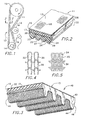
- an engine accessory drive system is shown generally at 10, consisting of an engine crankshaft pulley 14, and a driven pulley 12 linked in driving relationship by a four-ribbed serpentine belt 11.
- the top or exterior back surface of 13 of belt 11 makes contact with idler pulley 16.
- the drive system 10 of Fig. 1 may be used as a simple automotive accessory drive system, an industrial drive, or a test apparatus for measuring noise generated at the interface between belt 11 and backside idler pulley 16 through sensor/transducer 18 (measuring dB's and noise characteristics).
- sensor/transducer 18 measuring dB's and noise characteristics
- the principles of the invention may be applied to V-belts, flat belts, multi-V-ribbed belts and synchronous belts.
- An example of a common automotive front end accessory drive system in which the belt of the invention may be used is illustrated and disclosed in U.S. patent no. 4,551,120, which consists of a main driving pulley operatively connected to an air conditioning motor pulley, an alternator pulley, an engine air pump pulley, and a water pump pulley.
- the multi-V-ribbed belt trained about these pulleys is kept in appropriate tension through a tensioner having a surface engaging the backside of the belt.
- the belt of Fig. 2 is formed of a rubber body.
- rubber is meant a cross-linkable natural or synthetic rubber which is processable in solid form, e.g. on a mixing mill.
- Such rubber is typically mixed in a green or unvulcanized form with appropriate additives, extenders, reinforcements, accelerators, fillers, vulcanizing agents, e.g. sulfur and peroxides, and the like in a Banbury® mixer, or continuous mixer, well known in the rubber processing industry. Layers or calendared sheets of stock are then ready to be built up in layered form with textile reinforcement and the like.
- the green reinforced rubber in sleeve or other form is vulcanized or cured under heat and pressure.
- Typical synthetic rubbers useful in the invention include polychloroprene, copolymers of ethylene and propylene, terpolymers of ethylene, propylene and diene monomers, e.g. EPDM, styrene butadiene rubber, HNBR, CSM, silicone rubber, fluoroelastomers, mixtures of the foregoing, and alloys or mixtures of the foregoing or other known solid-processable rubbers mixed with suitable thermoplastic or thermosetting polymers or "plastomers", polyethylene, polyester (Hytrel trademark) or materials such as Santoprene (Monsanto trademark). Liquid processable elastomeric materials such as those formed by liquid casting, applicable to many forms of polyurethane, are not within this definition and are not contemplated by the invention.
- the belt of Fig. 2 is a four-ribbed serpentine belt employing a strain-resisting tensile member 20 which is embedded in the rubber body of the belt. It is positioned by helically winding it as will be discussed further in respect to the building process described with reference to Figs. 7 and 8.
- the tensile cord members may be any typical strain-resisting cord or members formed of nylon, polyester, carbon, aramid e.g. Kevlar®, or Twaron® fibers (both trademarks) and the like, and are typically formed of twisted yarns.
- the yarns are usually composed of many fibers.
- the cords may be sized or treated e.g.
- the undercord or compression section 22 of the belt may be formed of an unloaded rubber stock, however typically it is formed of a suitable rubber in which has been mixed loading of discrete reinforcement fibers 24 of desired material such as cotton, polyester or aramid.
- the multiple ribs of the undercord section shown at 23, 25, 27, 29 may be formed by grinding away the fiber loaded rubber between adjacent ribs, up to the apex 26 between adjacent ribs, or by molding, fly cutting or other technique.
- the shape and configuration of the ribs is normally substantially matched to the corresponding shape of the pulleys 12 and 14 about which the belt is linked in driving relationship.
- the overcord section of the belt shown at 28 includes a generally flat exterior belt back surface 13, an open mesh textile overcord material 15 positioned at the exterior belt back surface, and an interposed rubber layer such as adhesion gum layer 17 which is selected to adhere to the tubular knit textile material 15 as well as the adjoining cords 20.
- the adhesion gum layer 17 may be formed of the same or similar (compatible) rubber material as utilized in the undercord section 22 to ensure proper adhesion and integration into the composite belt structure.
- open mesh textile material as used in this invention is meant a textile material formed of interlacing yarns defined interstices (openings) between adjacent yarns, and which has an openness factor defined by formula (1) above.
- the openness factor is between about 0.20 and about 0.98 as provided above, more preferably from about 0.40 to about 0.92, and most preferably from about 0.70 to about 0.90.
- the individual yarns may be formed of multiple, continuous filaments, generally with a suitable degree of twist, however typically the yarns are formed of bundles of twisted staple fibers of any suitable material such as cotton, polyester, nylon, aramid, carbon or blends thereof or other spun yarns.
- the yarns may be comprised of individual elastic core filaments covered with a staple or texturized textile sheath. Yarns formed of monofilaments are not contemplated by this invention, since such monofilaments will generally retain their geometric shape and do not benefit from applying a stabilizing coating thereon, to ensure flow-through of rubber during the process of producing the belt.
- the yarns are typically interlaced to form a particular type of fabric, such as a square woven fabric, tire cord fabric, or bias-laid fabric in which the warp and weft yarns are oriented diagonally in respect to the longitudinal running direction of the belt, or the aforementioned Flex-Weave® fabric.
- a particular type of fabric such as a square woven fabric, tire cord fabric, or bias-laid fabric in which the warp and weft yarns are oriented diagonally in respect to the longitudinal running direction of the belt, or the aforementioned Flex-Weave® fabric.
- the open mesh textile material takes the form of a radially stretchable, preferably knit material.
- the open mesh textile material of the invention is in the form of a woven or knit fabric, or other form, it is important that the textile material is not pre-impregnated with a rubber material, such as by calendaring the textile material in a rubber calendar which fills the interstices of the textile material with rubber and applies a friction layer of rubber on either or both sides of the web of textile material being calendared.
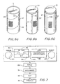
- the most preferred form of open mesh textile material is a radially stretchable, preferably knit material 15. It may be in the form of a seamless tube, such as shown at 30 in Fig. 9 of a rest diameter of D 1 which, because of inherent stretchability of up to 500% or more typically, may be expanded (at 30') to an increased diameter D 2 as shown.
- the normal diameter D 1 should be chosen to be equal to or preferably somewhat less than the diameter of the building drum or mandrel, with the rest diameter D 1 of the tubular knit textile material being preferably from about 20 to 100 and more preferably from about 30 to about 80 percent of the final diameter of the knit tube as applied in stretched condition on the building drum.
- the degree of expansion, and the corresponding opening size of interstices 33, 34 (Figs.
- tubular knit material 4 and 5
- its construction e.g. denier, fiber type and twist, and density of courses and wales
- Knit tube 30 (Fig. 9) is produced in a seamless tube form, i.e. the circular knitting process inherently produces a tube of a particular diameter D 1 depending on the preselected equipment components utilized in the knitting machine. It is contemplated that tubes 30 of a given diameter may be useful for more than one belt size given the significant stretchability of the knit tube itself. Different knit patterns may be employed, such as the rib-knit configuration shown in Fig. 4 in which the wales or vertical rows 35 of stitches of yarns 39 intermesh alternately on the face and the back of the knit. Rib-knit fabrics of this type have good elasticity, especially in the width direction. A jersey knit as shown in Fig.
- a circular knit fabric made with a plain stitch is currently the most preferred knit fabric for use with the invention.
- the technical face, as shown in Fig. 5, faces inwardly (toward the adhesion gum layer 17).
- the wales or rows extend vertically in the figures, as well as vertically in the tube of Fig. 9.
- Such orientation when applied to the belts of Fig. 2 and Fig. 3, for instance, will cause the wales or vertical rows of stitches to be oriented transversely to the longitudinal (running) direction of the completed belt.
- Other knit or radially stretchable configurations which can be formed into a seamless or seamed (e.g. sewn or spliced) tubular configuration with openings (interstices) allowing rubber flow through are also contemplated.
- Knit strip 37 which may be let off from a roll, can be formed from slitting a knit tube made on a circular knitting machine, or may be a flat knit or weft knit fabric made on a flat knitting machine. As shown in Fig. 6 (b), a strip or web of knit material 37 is applied to the surface of the drum (for production of a belt of the type shown in Fig.
- the knit material may be formed by spirally cutting a continuous long knit tube (only a segment of which is shown) as shown at 43, 45 at an acute angle, preferably from about 25 to about 65 degrees to the longitudinal axis L of the knit tube.
- a continuous strip 47 of knit material cut on a bias relative to the direction of the wales 35 of the knit is produced and this offers benefits by orienting the knit at a bias along the flat exterior belt back surface 13, enhancing the lateral flex properties of the top surface 13 of the belt 11.
- the strip 47 Once the strip 47 is produced from the continuous tube 49, the strip 47 would be collected on a roll and then payed off, as needed, for treating with the stabilizer material, followed by wrapping onto building drum 31 with an overlap as shown in Fig. 6 (b) as previously discussed.
- a square woven fabric 51 or a woven fabric with the warp and weft oriented with respect to one another at an included angle between the yarns of about 90-120 degrees (“Flex-Weave®”), may be applied to drum 31 with a seam 39 and overlap 41, similarly in respect to the embodiment shown in Fig. 6 (b).
- the open mesh textile material of the invention may also be applied to the building drum with the ends of the fabric butt spliced together in known fashion, including by ultrasonic welding, sewing or the like.
- an open mesh textile material as defined above, comprising interlaced yarns 53, 55, themselves formed of a bundle of staple or continuous filament fibers 57, usually twisted together as a spun yarn or multiple filament yarn. These yarns are treated by coating or otherwise to be at least partially covered, and impregnated within their own interstices of the yarn bundle, with the aforementioned stabilizer material 59.
- the most preferred stabilizer material currently envisioned is an RFL (resorcinol formaldehyde latex), which offers the benefits of rigidifying the yarn bundle to maintain its substantially round geometric shape during processing, as well as serving as an adhesive to promote bonding with adhesion gum rubber layer 17, and may have sufficient tack to hold together the overlap splice 41 (Figs 6(b) and 6(c)) during build, if an overlapped textile material is used.
- RFL resorcinol formaldehyde latex
- isocyanates such as MDI (methylene diisocyanate), and TDI (toluene diisocyanate) are similarly effective.
- Two component polyurethanes and rubber cements are additional materials which are usable in accordance with the invention as stabilizer materials to maintain the geometry of the yarn, while leaving the interstices 34 of the open mesh textile material open to allow unimpeded flow-through of rubber during vulcanization.
- the open mesh textile material with individual yarns being at least partially coated with stabilizer material 59 are first applied to the surface of mandrel 31, and then successive layers of adhesion gum rubber 17, spirally wound tensile cord 20 and undercord 22 are built up on the drum.
- the vulcanization process involves the application of heat and pressure to cause the belt component materials to be compressed toward the mandrel, consolidated and the rubber cross-linked through vulcanization under heat and pressure to form a consolidated cured belt sleeve.
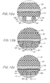
- an outer airbag formed of rubber 61 is pressurized radially inwardly toward mold 31 to press the belt elastomer components, which have become softened under the application of heat to move toward mandrel 31 which causes adhesion gum layer 17 to flow into the interstices 34 between adjacent yarns 53, 55, and to be pressed against the surface of the mold 31.
- stabilizing material coating 59 substantially maintains the geometric shape of the yarn bundles 53, 55 to maintain the maximum interstitial opening between the yarns 53, 55 and thereby allow maximum flow-through of adhesion gum rubber 17 to surface 63 of mold 31.
- the yarn tips at 65, 67 which are located at the outermost exterior surface at the top of the belt will be preferably free from full encapsulation by the rubber of the rubber body of the belt. That is, such yarn tips 65, 67 and associated staple fibers or filaments will be unencapsulated (but carry the stabilizer coating) to present at the back surface of the belt a desirable wear-resistant fabric surface.
- belt 40 is formed of a rubber body 42 in which is embedded a strain-resistant tensile cord 20.
- a series of cogs or teeth 44 are disposed on the underside of the belt adapted to mesh with corresponding teeth of a sprocket in gear-like fashion to transmit power in synchronization.
- Belt 40 similarly to multi-V-ribbed belt 11 discussed in respect to Fig. 2, employs an open mesh textile material 15 at the exterior back surface 13 of the belt.
- a layer 17 of rubber of adhesion gum type is interposed between cord 20 and the exterior belt surface 13, and during processing a portion of the rubber extrudes through the interstices e.g.
- the open mesh textile material may alternatively be formed of lapped or spliced knit, tire cord, square or bias-applied woven fabric, or Flex-Weave® fabric. In all cases the textile material is pretreated with the stabilizer material.
- the belt teeth 44 may, in customary fashion, carry an outer abrasion resistant tooth fabric layer 46 adhered to the rubber of the teeth.
- Typical suitable materials include a stretch nylon square woven fabric material or knit material.
- the teeth 44 may also include transverse stiffening elements or other reinforcements not shown.
- the method of producing a power transmission belt in accordance with the invention follows the sequential processing steps of Fig. 7 in which a vulcanizable belt sleeve is formed, then vulcanized, and then subject to optional additional cutting or profiling.
- the open mesh textile material 80 is played out from roll 81 and passed through dip tank 83 containing stabilizer material 59 e.g. solution of RFL having 10 to about 30 weight percent solids.
- a set of two rolls may be used to remove excess solution by pressing against each other with controlled pressure at the exit of the dip tank 83.
- Linear speed of the web, residence time within tank 83, solution weight percent solids, and pressure of the two rolls will determine the amount of pickup of stabilizer material on web 80, adjustable as desired.
- Other methods for applying the stabilizer coating may be used, such as spraying, brushing or electrostatic coating.
- the thus treated textile web 82 is then dried in oven 85 or in other suitable fashion and taken up on windup roll 87 and thereafter transferred to the build station 89.
- elongated transfer label 71 upon which is imprinted any desired indicia, e.g. product numbers, trademarks, country of origin, to be imparted to back surface 13 of the belt.
- This transfer label typically is a relatively thin film of Mylar or other plastic material bearing heat or pressure sensitive ink printing which during vulcanization is transferred from the Mylar backing to the outer surface 13 of the belt.
- the next layer applied on the drum is the open mesh textile material 15 of the invention including the seamed, spliced and lapped constructions described in relation to Fig. 6.
- the textile material is formed of seamless tube 30 of knit textile material of Fig. 9, which is expanded and elastically stretched sock-like over the mandrel 31 and grips, without wrinkles, against the outer surface of drum 31 with interposed transfer label 71.
- the wales 35 run longitudinally of the drum, i.e. parallel to its axis.
- elastomer such as adhesion gum rubber 17.
- the ends of the layer(s) are butt spliced to avoid a lap which might otherwise be reflected as a protrusion or bump in the exterior surface 13 of the belt.
- This gum layer 17 may alternatively be fiber loaded with any suitable reinforcement fiber such as cotton, polyester or aramid, or may itself include one or more textile reinforcing layers embedded therein.
- On to gum layer 17 is applied, by helically winding, strain-resisting tensile cord 20 in typical fashion. The tensile cord may be closely or widely spaced, as needed, and an appropriate amount of winding tension is used, with the ends 20a secured, as shown.
- layer 22 which will serve as the undercord of the belt, is wrapped over the helically wound cord 20.
- This material may be gum stock, or include discrete fiber loading 24 to enhance the modulus of the ribs 23, 25, 27, 29.
- the assembly may be placed inside a vulcanizing bag and kettle with steam pressure introduced to press the bag radially inwardly against the outer surface of the sleeve (against layer 22), consolidating and vulcanizing (91) the sleeve in customary manner.
- the mold may then be disassembled and the sleeve demolded.
- the sleeve may then be cut (93) into individual V-ribbed belts which are then placed on a grinding drum and the profile (95) of ribs 23, 25, 27, 29 formed with complimentary shaped grinding wheels or flycutters, removing undercord material between the ribs, and up to apices 26.
- the ribbed profile may be formed by molding by using a matrix airbag during vulcanization on drum 31, where the shape of the airbag is impressed into the overcord section 24.
- an airbag can be placed over the plied up build 24 and the sleeve pressed outwardly during vulcanization against a rigid outer shell member having the conjugate shape of ribs 23, 25, 27, 29 formed in the shell.
- the synchronous belt of Fig. 3 can also be formed on an appropriate apparatus similar to Fig. 8.
- the mandrel or drum 31 will typically have longitudinally extending teeth on its surface which form belt teeth 44.
- the radially outermost layer to be applied will be the open mesh textile material 15 in the form of tube 30 or any other desired form and then applied over the partially formed belt sleeve.
- an outer airbag will be used to press the rubber/composite materials radially inwardly against the toothed mold mandrel 31.
- the belt of Fig. 2 could also be built upright, rather than inverted.
- the outermost layer is preferably the open mesh textile material.
- the standard transfer label 71 may be employed without producing any, or any significant, discontinuities on the outer surface 13 of the belt which would otherwise serve as noise generators when impacting backside idlers or tensioners or other devices. That is, when the open mesh textile material is positioned at the exterior belt surface 13 as shown in Fig. 10 (b), with the outermost yarn fibers 65, 67 being free from full encapsulation by the rubber matrix, when the transfer label 71 is pressed against the outer surface 13 during vulcanization, the printed material is transferred to the back of the belt without substantially affecting its flat, generally planer outer surface (the step formed is generally less than about 0.03 mm).
- Two sets of belt sleeves A and B were constructed as follows.
- a tubular cotton jersey knit having a weight of 3.5 oz./yard 2 (118.7gm/m 2 ) was used having a nominal thickness of 0.38 mm, a yarn count of one (1) end/mm, a nominal yarn diameter of 0.2 mm, and each yarn formed of spun staple cotton fibers, having a dtex of 266.
- the knit material had an openness factor (formula (1)) of 0.8.
- the knit tube was supplied from a roll and passed through a dip tank by immersion in an RFL adhesive bath, with a solids content of 20 weight percent, excess adhesive removed by squeezing with rubber covered rolls, and dried in an oven at 175° C for one minute, and wound up on a spool.
- the RFL was based on a vinyl pyridine SBR latex, with a resorcinol-formaldehyde to latex ratio of 18.
- the dry amount of RFL deposited on the knit fabric was about 10 percent of the total weight of treated fabric.
- the belt sleeve was built inverted on a steel mandrel having a diameter of 39.0 cm by plying up the following layers: Ply Material Thickness layer 1 RFL coated knit 0.381 mm layer 2 EPDM gum stock 2 x 0.305 mm layer 3 polyester tensile cord 0.940 mm layer 4 undercord stock 5 x 0.762 mm
- the gum stock was Nordel 1145 EPDM (see U.S. patent no. 5,610,217).
- the jersey cotton tube was stretched to a diameter approximately 300 percent of the rest diameter of the coated tube.
- the tensile cord was RFL treated S and Z twist polyester, and the undercord stock was five plies of fiber load stock (25 parts cotton plus aramid fibers per 100 parts Nordel 1145 EPDM).
- the total build length (mold outside circumference) was 122.504 cm.
- the belt sleeve was cured using an outside (kettle) pressure of 200 psig (1.379 MPa) at 389° F (198° C) for 3 minutes, an inside (bag) pressure of 50 psig (.345 MPa) for 3.5 minutes increased to 150 psig (1.034 MPa) for 9.5 minutes. The cure was complete in 19.75 minutes.
- Belt sleeve B was constructed for comparison using the same materials and processing conditions as sleeve A except that the yarn of the knit tube was not treated with RFL or any other material.
- Belt sleeves A and B were cut into 20.0 mm wide belt strips which were then profiled by using a diamond grinding wheel to form four ribbed belts resembling that depicted in Fig. 2. Belts from sleeves A and B were tested to determine the coefficient of friction of their top surface 13.
- the test apparatus consisted primarily of a driven pulley of about 15 cm diameter with a flat outer surface against which the backside of the test belts were wrapped through an angle of 35 degrees.
- the test belts were trained about a driver pulley of about 15 cm diameter with about 180 degree wrap, a tensioner positioned between the drive and driven pulleys, and a hanging deadweight supplying constant tension on a third pulley over which the test belts are wrapped for about 180 degrees.
- belts from sleeve A had a calculated (formula (2)) dynamic coefficient of friction of 0.52, whereas belts from sleeve B had a calculated (formula (2)) dynamic coefficient of friction of 0.30.
- belts from sleeve B had a calculated (formula (2)) dynamic coefficient of friction of 0.30.
Landscapes
- Engineering & Computer Science (AREA)
- General Engineering & Computer Science (AREA)
- Mechanical Engineering (AREA)
- Devices For Conveying Motion By Means Of Endless Flexible Members (AREA)
- Belt Conveyors (AREA)
Priority Applications (1)
| Application Number | Priority Date | Filing Date | Title |
|---|---|---|---|
| EP08075662.0A EP1992837B1 (fr) | 1999-11-12 | 2000-11-09 | Méthode de production d'une courroie de transmission de puissance d'une façon verticale |
Applications Claiming Priority (4)
| Application Number | Priority Date | Filing Date | Title |
|---|---|---|---|
| US16538199P | 1999-11-12 | 1999-11-12 | |
| US20610200P | 2000-05-20 | 2000-05-20 | |
| US24058700P | 2000-10-13 | 2000-10-13 | |
| EP00978477A EP1228325B2 (fr) | 1999-11-12 | 2000-11-09 | Courroie de transmission d'energie a textile en treillis dans le tissu corde externe ameliorant la penetration du caoutchouc |
Related Parent Applications (1)
| Application Number | Title | Priority Date | Filing Date |
|---|---|---|---|
| EP00978477A Division EP1228325B2 (fr) | 1999-11-12 | 2000-11-09 | Courroie de transmission d'energie a textile en treillis dans le tissu corde externe ameliorant la penetration du caoutchouc |
Related Child Applications (1)
| Application Number | Title | Priority Date | Filing Date |
|---|---|---|---|
| EP08075662.0A Division EP1992837B1 (fr) | 1999-11-12 | 2000-11-09 | Méthode de production d'une courroie de transmission de puissance d'une façon verticale |
Publications (2)
| Publication Number | Publication Date |
|---|---|
| EP1630451A2 true EP1630451A2 (fr) | 2006-03-01 |
| EP1630451A3 EP1630451A3 (fr) | 2008-06-25 |
Family
ID=35721020
Family Applications (1)
| Application Number | Title | Priority Date | Filing Date |
|---|---|---|---|
| EP05077626A Withdrawn EP1630451A3 (fr) | 1999-11-12 | 2000-11-09 | Courroie de transmission avec revètement extérieur en matériau textile stabilisé à mailles ouvertes pour une pénétration améliorée du caoutchouc |
Country Status (1)
| Country | Link |
|---|---|
| EP (1) | EP1630451A3 (fr) |
Cited By (2)
| Publication number | Priority date | Publication date | Assignee | Title |
|---|---|---|---|---|
| WO2019118078A1 (fr) * | 2017-12-13 | 2019-06-20 | Gates Corporation | Courroie de transmission d'énergie crantée avec tissu de soutien |
| CN111335039A (zh) * | 2020-04-21 | 2020-06-26 | 济南天齐特种平带有限公司 | 一种脂肪族聚氨酯分散液的应用 |
Citations (2)
| Publication number | Priority date | Publication date | Assignee | Title |
|---|---|---|---|---|
| US3981206A (en) | 1975-08-20 | 1976-09-21 | Dayco Corporation | Endless power transmission belt |
| US5610217A (en) | 1994-10-31 | 1997-03-11 | The Gates Corporation | Ethylene-alpha-olefin belting |
Family Cites Families (4)
| Publication number | Priority date | Publication date | Assignee | Title |
|---|---|---|---|---|
| US4551120B2 (en) * | 1984-04-10 | 1990-05-08 | Belt tensioner | |
| JPH07167221A (ja) * | 1993-12-17 | 1995-07-04 | Bando Chem Ind Ltd | 動力伝動ベルト |
| JPH07243483A (ja) * | 1994-03-07 | 1995-09-19 | Bridgestone Corp | 伝動ベルト |
| JP3054046B2 (ja) * | 1994-11-28 | 2000-06-19 | 三ツ星ベルト株式会社 | マーク材を用いた伝動ベルトおよびベルトスリーブの製造方法 |
-
2000
- 2000-11-09 EP EP05077626A patent/EP1630451A3/fr not_active Withdrawn
Patent Citations (2)
| Publication number | Priority date | Publication date | Assignee | Title |
|---|---|---|---|---|
| US3981206A (en) | 1975-08-20 | 1976-09-21 | Dayco Corporation | Endless power transmission belt |
| US5610217A (en) | 1994-10-31 | 1997-03-11 | The Gates Corporation | Ethylene-alpha-olefin belting |
Cited By (2)
| Publication number | Priority date | Publication date | Assignee | Title |
|---|---|---|---|---|
| WO2019118078A1 (fr) * | 2017-12-13 | 2019-06-20 | Gates Corporation | Courroie de transmission d'énergie crantée avec tissu de soutien |
| CN111335039A (zh) * | 2020-04-21 | 2020-06-26 | 济南天齐特种平带有限公司 | 一种脂肪族聚氨酯分散液的应用 |
Also Published As
| Publication number | Publication date |
|---|---|
| EP1630451A3 (fr) | 2008-06-25 |
Similar Documents
| Publication | Publication Date | Title |
|---|---|---|
| EP1228325B1 (fr) | Courroie de transmission d'energie a textile en treillis dans le tissu corde externe ameliorant la penetration du caoutchouc | |
| EP1235996B1 (fr) | Courroie de transmission de puissance comportant une gaine tubulaire tricotee | |
| KR910001826B1 (ko) | 로에지 톱니형 v-벨트 및 그 제조방법 | |
| EP1630451A2 (fr) | Courroie de transmission avec revètement extérieur en matériau textile stabilisé à mailles ouvertes pour une pénétration améliorée du caoutchouc | |
| KR100382748B1 (ko) | 고무의 침투를 강화하기 위해 오버코드에 안정화된 망포재료를 사용한 동력 전달 벨트 | |
| JPS6228340B2 (fr) | ||
| KR100388712B1 (ko) | 관형 편물 오버코드를 구비한 동력 전달 벨트 | |
| JPS6323413B2 (fr) | ||
| JPS5849745B2 (ja) | 多リブベルト及びその製造方法 | |
| JP2001090784A (ja) | 低騒音歯付ベルト | |
| JPS5852100B2 (ja) | Vベルト及びその製造方法 | |
| JP2001041292A (ja) | 動力伝動用ベルト |
Legal Events
| Date | Code | Title | Description |
|---|---|---|---|
| PUAI | Public reference made under article 153(3) epc to a published international application that has entered the european phase |
Free format text: ORIGINAL CODE: 0009012 |
|
| AC | Divisional application: reference to earlier application |
Ref document number: 1228325 Country of ref document: EP Kind code of ref document: P |
|
| AK | Designated contracting states |
Kind code of ref document: A2 Designated state(s): AT BE CH CY DE DK ES FI FR GB GR IE IT LI LU MC NL PT SE TR |
|
| AX | Request for extension of the european patent |
Extension state: AL LT LV MK RO SI |
|
| RIN1 | Information on inventor provided before grant (corrected) |
Inventor name: KNUTSON, PAUL S. |
|
| PUAL | Search report despatched |
Free format text: ORIGINAL CODE: 0009013 |
|
| AK | Designated contracting states |
Kind code of ref document: A3 Designated state(s): AT BE CH CY DE DK ES FI FR GB GR IE IT LI LU MC NL PT SE TR |
|
| AX | Request for extension of the european patent |
Extension state: AL LT LV MK RO SI |
|
| RIC1 | Information provided on ipc code assigned before grant |
Ipc: B29D 29/00 20060101ALI20080522BHEP Ipc: F16G 5/20 20060101ALI20080522BHEP Ipc: F16G 1/28 20060101AFI20060106BHEP |
|
| 17P | Request for examination filed |
Effective date: 20081224 |
|
| STAA | Information on the status of an ep patent application or granted ep patent |
Free format text: STATUS: THE APPLICATION HAS BEEN WITHDRAWN |
|
| AKX | Designation fees paid |
Designated state(s): AT BE CH CY DE DK ES FI FR GB GR IE IT LI LU MC NL PT SE TR |
|
| 18W | Application withdrawn |
Effective date: 20090210 |