EP1630378B1 - Kühlsytem und Brennkraftmaschine mit dem Kühlsystem - Google Patents
Kühlsytem und Brennkraftmaschine mit dem Kühlsystem Download PDFInfo
- Publication number
- EP1630378B1 EP1630378B1 EP05255089A EP05255089A EP1630378B1 EP 1630378 B1 EP1630378 B1 EP 1630378B1 EP 05255089 A EP05255089 A EP 05255089A EP 05255089 A EP05255089 A EP 05255089A EP 1630378 B1 EP1630378 B1 EP 1630378B1
- Authority
- EP
- European Patent Office
- Prior art keywords
- coolant
- path
- cooling system
- bubbles
- internal combustion
- Prior art date
- Legal status (The legal status is an assumption and is not a legal conclusion. Google has not performed a legal analysis and makes no representation as to the accuracy of the status listed.)
- Expired - Lifetime
Links
Images



Classifications
-
- F—MECHANICAL ENGINEERING; LIGHTING; HEATING; WEAPONS; BLASTING
- F01—MACHINES OR ENGINES IN GENERAL; ENGINE PLANTS IN GENERAL; STEAM ENGINES
- F01P—COOLING OF MACHINES OR ENGINES IN GENERAL; COOLING OF INTERNAL-COMBUSTION ENGINES
- F01P11/00—Component parts, details, or accessories not provided for in, or of interest apart from, groups F01P1/00 - F01P9/00
- F01P11/02—Liquid-coolant filling, overflow, venting, or draining devices
- F01P11/0285—Venting devices
-
- F—MECHANICAL ENGINEERING; LIGHTING; HEATING; WEAPONS; BLASTING
- F01—MACHINES OR ENGINES IN GENERAL; ENGINE PLANTS IN GENERAL; STEAM ENGINES
- F01P—COOLING OF MACHINES OR ENGINES IN GENERAL; COOLING OF INTERNAL-COMBUSTION ENGINES
- F01P11/00—Component parts, details, or accessories not provided for in, or of interest apart from, groups F01P1/00 - F01P9/00
- F01P11/02—Liquid-coolant filling, overflow, venting, or draining devices
- F01P11/028—Deaeration devices
-
- F—MECHANICAL ENGINEERING; LIGHTING; HEATING; WEAPONS; BLASTING
- F01—MACHINES OR ENGINES IN GENERAL; ENGINE PLANTS IN GENERAL; STEAM ENGINES
- F01P—COOLING OF MACHINES OR ENGINES IN GENERAL; COOLING OF INTERNAL-COMBUSTION ENGINES
- F01P2060/00—Cooling circuits using auxiliaries
- F01P2060/08—Cabin heater
Definitions
- the present invention relates to a cooling system and an internal combustion engine provided with this cooling system.
- One known arrangement of the cooling system of this type is to perform cooling by circulating the cooling water through the cylinder head and cylinder block by means of a water pump driven by the internal combustion engine, as disclosed in the following non-patent document 1, for example.
- the cooling water after cooling the cylinder head and cylinder block is returned to the water pump through a radiator and a heater, etc.
- the returned cooling water is supplied again to the cylinder head and cylinder block through the water pump.
- Non-patent document 1 Service Manual HONDA ACCORD
- the present invention is worked out in view of the above-described problems in the prior art. It is an aim of the present invention to provide a cooling system that is capable of removing the bubbles contained in the cooling water or coolant and returning the coolant without the bubbles into a coolant pumping means.
- the foregoing aim is addressed by the cooling system of claim 1. Accordingly, in this cooling system, the bubbles are prevented from entering the coolant pumping means, the efficiency of which is prevented from lowering, so that the cooling performance of the cooling system may be improved.
- Another aim of the present invention is to provide an internal combustion engine having a cooling system that is capable of removing bubbles contained in the coolant and returning the coolant without the bubbles into a coolant pumping means. Accordingly, in this internal combustion engine, the cooling performance of the engine may be improved.
- the coolant returning means is a means for removing bubbles contained in the coolant after cooling the internal combustion engine and for returning the coolant to the coolant pumping means. Accordingly, it is possible to remove the bubbles generated due to vaporization of a part of the coolant while cooling the internal combustion engine.
- the coolant returning means has a first path for returning the coolant to the coolant pumping means through a bubble removing portion capable of removing the bubbles, and a second path for returning the coolant to the coolant pumping means not through the bubble removing portion.
- a bubble introducing portion capable of introducing the bubbles into the bubble removing portion through the first path. Accordingly, since the bubbles contained in the coolant flowing in the second path may be introduced through the bubble introducing portion into the bubble removing portion in the first path, the coolant containing bubbles may be well prevented from being returned into the coolant pumping means.
- the coolant returning means has a coolant distributing means comprising a feeding chamber for feeding the coolant after cooling the internal combustion engine into the first path and/or the second path; and a receiving chamber provided as a part of the second path under the feeding chamber for receiving the coolant fed into the second path from the feeding chamber and for returning the coolant into the coolant pumping means.
- the foregoing bubble introducing portion is a means for making the upper portion of the receiving chamber communicate with the feeding chamber. Accordingly, the bubbles within the coolant fed into the second path may be well removed by means of such a simple construction as making the upper portion of the receiving chamber communicate with the feeding chamber.
- the coolant distributing means has a mating surface with the internal combustion engine; the feeding and the receiving chamber are divided by a partition formed as a part of the mating surface; and the bubble introducing portion is a notch formed in the partition. Accordingly, the bubble introducing portion may be realized in a simple construction such as a notch preventing from increasing the numbers of parts.
- the first path is provided with a heat radiating means for radiating the heat of the coolant and the bubble removing portion is formed in the heat radiating means.
- the bubble removing portion is formed as a cap in the existing radiator, so that it is possible to prevent from increasing the numbers of parts.
- an outlet 1a for coolant used to cool the interior of the internal combustion engine in the side surface of a cylinder head 1 constructing an internal combustion engine is provided an outlet 1a for coolant used to cool the interior of the internal combustion engine. Also, in the inside of the cylinder head 1 is formed a suction passage 1b to return the coolant into a water pump (coolant pumping means, not shown).
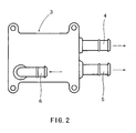
- a water outlet 3 (coolant distributing means) through a gasket 2 by means of bolts.
- This water outlet (coolant distributing means) 3 has a mating surface 3a mating with the side surface of the cylinder head 1 through the gasket 2.
- a feeding chamber 3c and a receiving chamber 3d are provided and respectively positioned above and below a partition 3b interposed therebetween.
- the upper portion of this receiving chamber 3d communicates with lower portion of the feeding chamber 3c through a notch 3e (bubble introducing means) formed vertically in a groove shape in the mating surface 3a.
- radiator connector 4 communicating with the inside of the feeding chamber 3c and forming the first path A.
- the radiator connector 4 in this embodiment is illustrated in the right side of the water outlet 3 for the sake of convenience to clarify the interior structure of the water outlet 3, the connector 4 may be provided either on the left side or on the top of the water outlet 3.
- a heater connector 5 communicating with the inside feeding chamber 3c
- a heater return connector 6 communicating with the inside receiving chamber 3d.
- the radiator connector 4 is to be connected to a hose communicating with a radiator (not shown).
- the coolant is supplied from the radiator connector 4 through this hose to the radiator (heat radiating means), in which the coolant is cooled and returned to a water pump (not shown).
- the radiator is provided with a cap, which constructs a bubble removing portion to discharge bubbles within the coolant outside.
- the heater connector 5 is to be connected to a hose connected to a heater core (not shown).
- the coolant is supplied from the heater connector 5 through this hose to the heater core, from which the coolant is returned through a hose (not shown) to the heater return connector 6.
- the coolant is supplied from the water pump into the cylinder head 1 and cylinder block to cool the inside thereof.
- the coolant is introduced from the coolant outlet 1a of the cylinder head 1 into the feeding chamber 3c of the water outlet 3.
- the radiator connector 4 constructing the first path A into the radiator (heat radiating means).
- the coolant is cooled in the radiator and simultaneously the bubbles contained in the coolant are drawn out of the cap (bubble removing portion) of the radiator. After that, the coolant is returned into the water pump (coolant pumping means).
- the coolant is fed from the feeding chamber 3c through the heater connector 5 into the heater core (not shown).
- the coolant is returned from the heater core through the heater return connector 6 into the receiving chamber 3d of the water outlet 3. Further, the coolant is returned from the receiving chamber 3d through the suction passage 1b formed inside the cylinder head 1 to the water pump (not shown).
- the coolant that is fed from the radiator connector through the first path A into the radiator (heat radiating means) the bubbles in the coolant are removed at the cap (bubble removing portion) of the radiator, and then the coolant is returned to the water pump.
- the coolant that is fed from the heater connector 5 into the heater core (not shown) and returned through the second path B (the return connector 6, receiving chamber 3d and suction passage 1b) into the water pump (not shown) if a part of the coolant is vaporized and bubbles are generated within the coolant, the coolant in case of the prior art may be returned into the water pump as containing the bubbles.
- the bubbles within the coolant entered the receiving chamber 3d of the second path B float up through the notch (bubble introducing portion) 3e formed in the water outlet 3 into the feeding chamber 3c. Further, the bubbles are carried from the feeding chamber 3c through the first path A and removed out of the radiator cap. Accordingly, the bubbles are prevented from entering the water pump (coolant pumping means) without lowering its efficiency, so that the cooling performance of the cooling system may be improved.
- the water outlet (coolant distributing means) 3 and the radiator with a cap (bubble removing portion, not shown) compose a coolant returning means.
- the interior of a water outlet 3 is divided into a feeding chamber 3c composing the first path A and a receiving chamber 3d composing the second path B and the receiving chamber 3d communicates with the feeding chamber 3c through a notch (bubble introducing portion) 3e
- the bubbles contained in the coolant flowing through the second path B is well introduced through the notch 3e into the feeding chamber 3c of the first path A. Then, the bubbles may be removed from the coolant and discharged out of the radiator cap in the first path A.
- FIG.4 showing a schematic perspective view of another embodiment, a water outlet 3 is fixedly mounted through a gasket on one side of a cylinder head 1 composing an internal combustion engine.
- a radiator connector 4 On the top of the water outlet 3 is provided a radiator connector 4, to which is connected a radiator passage 7 composing the first path A.
- a radiator passage 7 Through the radiator passage 7 into a radiator (not shown) is fed a coolant, so that the bubbles in the coolant are drawn out at a cap (bubble removing portion, not shown) provided on the radiator. Then, the coolant is returned through a radiator return passage 8 composing the first path A into a water pump (coolant pumping means) 9.
- a heater connector 5 connected to a heater passage 10 having one end connected to a heater core 11.
- a heater return passage 12 which is connected to a suction passage 13, which is further connected to the water pump 9.
- the coolant from the heater core 11 is returned through the heater return passage 12 and suction passage 13, both of which compose the second path B, into the water pump 9.
- a bypass passage 14 (bubble introducing portion) that makes this suction passage 13 communicate with the inside of the water outlet 3.
- the bubbles contained in the coolant are carried through the heater return passage 12 into the suction passage 13, from which the bubbles are introduced through the bypass passage 14 into the water outlet 3. Then, the bubbles are carried through the radiator connector 4 into the radiator and removed at the radiator cap (bubble removing portion).
- the bubbles in the coolant may be well removed by utilizing the cap (bubble removing portion) of the existing radiator (heat radiating means). Since no bubbles are transferred into the water pump 9, the efficiency of the water pump 9 is prevented from lowering and the cooling performance of the cooling system may be improved.
Landscapes
- Engineering & Computer Science (AREA)
- Chemical & Material Sciences (AREA)
- Combustion & Propulsion (AREA)
- Mechanical Engineering (AREA)
- General Engineering & Computer Science (AREA)
- Cylinder Crankcases Of Internal Combustion Engines (AREA)
- Details Of Reciprocating Pumps (AREA)
Claims (5)
- Kühlsystem zum Durchführen der Kühlung eines Verbrennungsmotors mittels eines umlaufenden Kühlmittels, welches umfasst:- Kühlmittel-Pumpmittel zum Pumpen des Kühlmittels; und- Kühlmittel-Rückleitmittel (3) zum Entfernen von in dem Kühlmittel eingeschlossenen Blasen und zum Rückleiten des Kühlmittels ohne Blasen zu dem Kühlmittel-Pumpmittel;wobei das Kühlmittel-Rückleitmittel einen ersten Weg (A) zum Rückleiten des Kühlmittels zu dem Kühlmittel-Pumpmittel durch einen Blasenentfernungsteil, der Blasen entfernen kann, und einen zweiten Weg (B) zum Rückleiten des Kühlmittels zu dem Kühlmittel-Pumpmittel nicht durch den Blasenentfernungsteil umfasst; und wobei der zweite Weg (B) einen darin ausgebildeten Blaseneinbringungsteil (3e) aufweist, der die Blasen durch den ersten Weg in den Blasenentfernungsteil einbringen kann; und dadurch gekennzeichnet, dass:- das Kühlmittel-Rückleitmittel ein Kühlmittel-Verteilungsmittel (3) aufweist, welches umfasst: eine Einspeisungskammer zum Einspeisen des Kühlmittels nach Kühlen des Verbrennungsmotors in den ersten Weg (A) und/oder den zweiten Weg (B); und eine als Teil des zweiten Wegs (B) unter der Einspeisungskammer vorgesehene Aufnahmekammer zum Aufnehmen des von der Einspeisungskammer in den zweiten Weg (B) eingespeisten Kühlmittels; und dass der Blaseneinbringungsteil (3e) ein Mittel zum in Verbindung setzen des oberen Teils der Aufnahmekammer mit der Einspeisungskammer ist.
- Kühlsystem nach Anspruch 1, dadurch gekennzeichnet, dass das Kühlmittel-Rückleitmittel (3) ein Mittel zum Entfernen von nach Kühlen des Verbrennungsmotors in dem Kühlmittel enthaltenen Blasen und zum Rückleiten des Kühlmittels zu dem Kühlmittel-Pumpmittel ist.
- Kühlsystem nach Anspruch 1, dadurch gekennzeichnet, dass das Kühlmittel-Verteilungsmittel (3) ein Passfläche (3a) mit dem Verbrennungsmotor aufweist; die Einspeisung- (3c) und die Aufnahmekammer (3d) durch eine Abtrennung (3b), die als ein Teil der Passfläche (3a) ausgebildet ist, getrennt sind; und der Blaseneinbringungsteil eine in der Abtrennung (3b) ausgebildete Kerbe (3e) ist.
- Kühlsystem nach einem der Ansprüche 1 bis 3, dadurch gekennzeichnet, dass der erst Weg mit einem Wärmeabstrahlmittel zum Abstrahlen der Wärme des Kühlmittels versehen ist; und der Blasenentfernungsteil in dem Wärmeabstrahlmittel ausgebildet ist.
- Verbrennungsmotor, der mit dem Kühlsystem nach einem der Ansprüche 1 bis 4 versehen ist.
Applications Claiming Priority (1)
| Application Number | Priority Date | Filing Date | Title |
|---|---|---|---|
| JP2004253639A JP4286197B2 (ja) | 2004-08-31 | 2004-08-31 | 冷却装置およびこれを備える内燃機関 |
Publications (2)
| Publication Number | Publication Date |
|---|---|
| EP1630378A1 EP1630378A1 (de) | 2006-03-01 |
| EP1630378B1 true EP1630378B1 (de) | 2008-06-11 |
Family
ID=35456888
Family Applications (1)
| Application Number | Title | Priority Date | Filing Date |
|---|---|---|---|
| EP05255089A Expired - Lifetime EP1630378B1 (de) | 2004-08-31 | 2005-08-17 | Kühlsytem und Brennkraftmaschine mit dem Kühlsystem |
Country Status (5)
| Country | Link |
|---|---|
| US (1) | US7308870B2 (de) |
| EP (1) | EP1630378B1 (de) |
| JP (1) | JP4286197B2 (de) |
| CN (1) | CN100520005C (de) |
| DE (1) | DE602005007436D1 (de) |
Families Citing this family (4)
| Publication number | Priority date | Publication date | Assignee | Title |
|---|---|---|---|---|
| KR101596700B1 (ko) * | 2014-05-27 | 2016-02-23 | 현대자동차주식회사 | 배기열 회수장치의 기포 배출구조 |
| JP6512290B2 (ja) | 2015-06-25 | 2019-05-15 | 日産自動車株式会社 | 鋳造装置及び鋳造方法 |
| CN106658770A (zh) * | 2016-12-27 | 2017-05-10 | 芜湖艾尔达科技有限责任公司 | 加热组件 |
| US12650265B2 (en) * | 2022-02-23 | 2026-06-09 | Sanhua Holding Group Co., Ltd. | Collector assembly and heat exchanger with simplified structure |
Family Cites Families (10)
| Publication number | Priority date | Publication date | Assignee | Title |
|---|---|---|---|---|
| US3384304A (en) * | 1967-04-03 | 1968-05-21 | Barlow Vapor Cooling Company | Ebullient cooling system for automotive gasoline engines with constant temperature passenger space heater |
| FR2317489A1 (fr) * | 1975-07-11 | 1977-02-04 | Citroen Sa | Perfectionnements apportes aux circuits de refroidissement pour moteurs a combustion |
| FR2514479B1 (fr) * | 1981-10-13 | 1987-05-07 | Valeo | Echangeur de chaleur a circulation de liquide, en particulier pour un vehicule automobile |
| JP2950553B2 (ja) * | 1989-09-26 | 1999-09-20 | 株式会社日本自動車部品総合研究所 | 内燃機関の冷却装置 |
| US5092282A (en) * | 1990-06-21 | 1992-03-03 | Volkswagen Ag | Evaporation cooling system for an internal combustion engine |
| US5139082A (en) * | 1990-08-31 | 1992-08-18 | Teledyne Industries, Inc. | Cooling system for a liquid cooled engine |
| US5255635A (en) * | 1990-12-17 | 1993-10-26 | Volkswagen Ag | Evaporative cooling system for an internal combustion engine having a coolant equalizing tank |
| US5385123A (en) * | 1993-10-08 | 1995-01-31 | Evans; John W. | Segregated cooling chambers for aqueous reverse-flow engine cooling systems |
| DE19538239C1 (de) * | 1995-10-13 | 1997-04-24 | Daimler Benz Ag | Kühlmittelführung in einem Kühlkreislauf einer flüssigkeitsgekühlten Brennkraftmaschine |
| SE521618C2 (sv) * | 1998-07-31 | 2003-11-18 | Volvo Lastvagnar Ab | Förfarande och anordning för avluftning av ett kylvätskesystem till en förbränningsmotor |
-
2004
- 2004-08-31 JP JP2004253639A patent/JP4286197B2/ja not_active Expired - Lifetime
-
2005
- 2005-08-15 US US11/203,102 patent/US7308870B2/en not_active Expired - Lifetime
- 2005-08-17 DE DE602005007436T patent/DE602005007436D1/de not_active Expired - Lifetime
- 2005-08-17 EP EP05255089A patent/EP1630378B1/de not_active Expired - Lifetime
- 2005-08-25 CN CNB2005100969035A patent/CN100520005C/zh not_active Expired - Lifetime
Also Published As
| Publication number | Publication date |
|---|---|
| US20060042568A1 (en) | 2006-03-02 |
| JP2006070759A (ja) | 2006-03-16 |
| JP4286197B2 (ja) | 2009-06-24 |
| US7308870B2 (en) | 2007-12-18 |
| CN100520005C (zh) | 2009-07-29 |
| CN1743648A (zh) | 2006-03-08 |
| EP1630378A1 (de) | 2006-03-01 |
| DE602005007436D1 (de) | 2008-07-24 |
Similar Documents
| Publication | Publication Date | Title |
|---|---|---|
| US6216646B1 (en) | Deaeration bottle for liquid cooling systems for automotive vehicle engines | |
| US6247442B1 (en) | Combined air box, coolant reservoir and oil tank for snowmobiles | |
| US6332505B1 (en) | Radiator structure for motorcycle | |
| CN208861238U (zh) | 具水冷散热功能的电子装置及其水冷散热模组与水冷排 | |
| US20200386145A1 (en) | Reservoir tank with integrated ejector | |
| US12066020B2 (en) | Heat exchanger assembly with heat shielding duct | |
| CN100398804C (zh) | 纵式多气缸发动机的水冷装置 | |
| GB2561599A (en) | Cooling system | |
| KR101416419B1 (ko) | 차량용 라디에이터 | |
| US7308870B2 (en) | Coolant distributing means for an internal combustion engine | |
| CN110886645B (zh) | 内燃机主体 | |
| US20090235878A1 (en) | Cooling apparatus of v-type internal combustion engine | |
| US20170254252A1 (en) | Engine having water jacket | |
| EP3769992B1 (de) | Nutzfahrzeug | |
| EP1765613A2 (de) | Kühlsystem für ein amphibienfahrzeug | |
| CN216111027U (zh) | 发动机缸体、砂芯、发动机和车辆 | |
| CA1091112A (en) | Radiator top tank with plural sump lines | |
| KR100534895B1 (ko) | 자동차용 라디에이터 구조 | |
| EP1775433A2 (de) | Ölfiltereinheit und Motorrad mit der Ölfiltereinheit | |
| KR101588791B1 (ko) | 차량용 라디에이터 | |
| KR100692760B1 (ko) | 브이형 엔진의 냉각 시스템 | |
| EP3300937A1 (de) | Kühlmittelausgleichsbehälter | |
| CN214008023U (zh) | 一种汽车电机减速机 | |
| KR20220070874A (ko) | 냉각수 리저버 탱크 | |
| JP2003222022A (ja) | エンジン冷却構造 |
Legal Events
| Date | Code | Title | Description |
|---|---|---|---|
| PUAI | Public reference made under article 153(3) epc to a published international application that has entered the european phase |
Free format text: ORIGINAL CODE: 0009012 |
|
| AK | Designated contracting states |
Kind code of ref document: A1 Designated state(s): AT BE BG CH CY CZ DE DK EE ES FI FR GB GR HU IE IS IT LI LT LU LV MC NL PL PT RO SE SI SK TR |
|
| AX | Request for extension of the european patent |
Extension state: AL BA HR MK YU |
|
| 17P | Request for examination filed |
Effective date: 20060404 |
|
| AKX | Designation fees paid |
Designated state(s): DE FR GB |
|
| GRAP | Despatch of communication of intention to grant a patent |
Free format text: ORIGINAL CODE: EPIDOSNIGR1 |
|
| GRAS | Grant fee paid |
Free format text: ORIGINAL CODE: EPIDOSNIGR3 |
|
| GRAA | (expected) grant |
Free format text: ORIGINAL CODE: 0009210 |
|
| AK | Designated contracting states |
Kind code of ref document: B1 Designated state(s): DE FR GB |
|
| REG | Reference to a national code |
Ref country code: GB Ref legal event code: FG4D |
|
| REF | Corresponds to: |
Ref document number: 602005007436 Country of ref document: DE Date of ref document: 20080724 Kind code of ref document: P |
|
| PLBE | No opposition filed within time limit |
Free format text: ORIGINAL CODE: 0009261 |
|
| STAA | Information on the status of an ep patent application or granted ep patent |
Free format text: STATUS: NO OPPOSITION FILED WITHIN TIME LIMIT |
|
| 26N | No opposition filed |
Effective date: 20090312 |
|
| REG | Reference to a national code |
Ref country code: FR Ref legal event code: PLFP Year of fee payment: 12 |
|
| REG | Reference to a national code |
Ref country code: FR Ref legal event code: PLFP Year of fee payment: 13 |
|
| REG | Reference to a national code |
Ref country code: FR Ref legal event code: PLFP Year of fee payment: 14 |
|
| REG | Reference to a national code |
Ref country code: DE Ref legal event code: R081 Ref document number: 602005007436 Country of ref document: DE Owner name: NISSAN MOTOR CO., LTD., YOKOHAMA-SHI, JP Free format text: FORMER OWNERS: NISSAN MOTOR CO., LTD., YOKOHAMA-SHI, KANAGAWA-KEN, JP; AICHI MACHINE INDUSTRY CO., LTD., NAGOYA-SHI, AICHI, JP Ref country code: DE Ref legal event code: R082 Ref document number: 602005007436 Country of ref document: DE Representative=s name: GRUENECKER PATENT- UND RECHTSANWAELTE PARTG MB, DE |
|
| REG | Reference to a national code |
Ref country code: GB Ref legal event code: 732E Free format text: REGISTERED BETWEEN 20220630 AND 20220706 |
|
| PGFP | Annual fee paid to national office [announced via postgrant information from national office to epo] |
Ref country code: DE Payment date: 20240723 Year of fee payment: 20 |
|
| PGFP | Annual fee paid to national office [announced via postgrant information from national office to epo] |
Ref country code: GB Payment date: 20240723 Year of fee payment: 20 |
|
| PGFP | Annual fee paid to national office [announced via postgrant information from national office to epo] |
Ref country code: FR Payment date: 20240723 Year of fee payment: 20 |
|
| REG | Reference to a national code |
Ref country code: DE Ref legal event code: R071 Ref document number: 602005007436 Country of ref document: DE |
|
| REG | Reference to a national code |
Ref country code: GB Ref legal event code: PE20 Expiry date: 20250816 |