EP1630378A1 - Cooling system and internal combustion engine with the cooling system - Google Patents
Cooling system and internal combustion engine with the cooling system Download PDFInfo
- Publication number
- EP1630378A1 EP1630378A1 EP05255089A EP05255089A EP1630378A1 EP 1630378 A1 EP1630378 A1 EP 1630378A1 EP 05255089 A EP05255089 A EP 05255089A EP 05255089 A EP05255089 A EP 05255089A EP 1630378 A1 EP1630378 A1 EP 1630378A1
- Authority
- EP
- European Patent Office
- Prior art keywords
- coolant
- path
- cooling system
- internal combustion
- combustion engine
- Prior art date
- Legal status (The legal status is an assumption and is not a legal conclusion. Google has not performed a legal analysis and makes no representation as to the accuracy of the status listed.)
- Granted
Links
Images



Classifications
-
- F—MECHANICAL ENGINEERING; LIGHTING; HEATING; WEAPONS; BLASTING
- F01—MACHINES OR ENGINES IN GENERAL; ENGINE PLANTS IN GENERAL; STEAM ENGINES
- F01P—COOLING OF MACHINES OR ENGINES IN GENERAL; COOLING OF INTERNAL-COMBUSTION ENGINES
- F01P11/00—Component parts, details, or accessories not provided for in, or of interest apart from, groups F01P1/00 - F01P9/00
- F01P11/02—Liquid-coolant filling, overflow, venting, or draining devices
- F01P11/0285—Venting devices
-
- F—MECHANICAL ENGINEERING; LIGHTING; HEATING; WEAPONS; BLASTING
- F01—MACHINES OR ENGINES IN GENERAL; ENGINE PLANTS IN GENERAL; STEAM ENGINES
- F01P—COOLING OF MACHINES OR ENGINES IN GENERAL; COOLING OF INTERNAL-COMBUSTION ENGINES
- F01P11/00—Component parts, details, or accessories not provided for in, or of interest apart from, groups F01P1/00 - F01P9/00
- F01P11/02—Liquid-coolant filling, overflow, venting, or draining devices
- F01P11/028—Deaeration devices
-
- F—MECHANICAL ENGINEERING; LIGHTING; HEATING; WEAPONS; BLASTING
- F01—MACHINES OR ENGINES IN GENERAL; ENGINE PLANTS IN GENERAL; STEAM ENGINES
- F01P—COOLING OF MACHINES OR ENGINES IN GENERAL; COOLING OF INTERNAL-COMBUSTION ENGINES
- F01P2060/00—Cooling circuits using auxiliaries
- F01P2060/08—Cabin heater
Definitions
- the present invention relates to a cooling system and an internal combustion engine provided with this cooling system.
- One known arrangement of the cooling system of this type is to perform cooling by circulating the cooling water through the cylinder head and cylinder block by means of a water pump driven by the internal combustion engine, as disclosed in the following non-patent document 1, for example.
- the cooling water after cooling the cylinder head and cylinder block is returned to the water pump through a radiator and a heater, etc.
- the returned cooling water is supplied again to the cylinder head and cylinder block through the water pump.
- Non-patent document 1 Service Manual HONDA ACCORD
- the present invention is worked out in view of the above-described problems in the prior art. It is an object of the present invention to provide a cooling system that is capable of removing the bubbles contained in the cooling water or coolant and returning the coolant without the bubbles into a coolant pumping means.
- the foregoing object is accomplished by a cooling system for performing the cooling of an internal combustion engine by means of circulating coolant.
- the cooling system includes a coolant pumping means for pumping the coolant; and a coolant returning means for removing bubbles included in the coolant and for returning the coolant without bubbles to the coolant pumping means. Accordingly, in this cooling system, the bubbles are prevented from entering the coolant pumping means, the efficiency of which is prevented from lowering, so that the cooling performance of the cooling system may be improved.
- Another object of the present invention is to provide an internal combustion engine having a cooling system that is capable of removing bubbles contained in the coolant and returning the coolant without the bubbles into a coolant pumping means. Accordingly, in this internal combustion engine, the cooling performance of the engine may be improved.
- the coolant returning means is a means for removing bubbles contained in the coolant after cooling the internal combustion engine and for returning the coolant to the coolant pumping means. Accordingly, it is possible to remove the bubbles generated due to vaporization of a part of the coolant while cooling the internal combustion engine.
- the coolant returning means has a first path for returning the coolant to the coolant pumping means through a bubble removing portion capable of removing the bubbles, and a second path for returning the coolant to the coolant pumping means not through the bubble removing portion.
- a bubble introducing portion capable of introducing the bubbles into the bubble removing portion through the first path. Accordingly, since the bubbles contained in the coolant flowing in the second path may be introduced through the bubble introducing portion into the bubble removing portion in the first path, the coolant containing bubbles may be well prevented from being returned into the coolant pumping means.
- the coolant returning means has a coolant distributing means comprising a feeding chamber for feeding the coolant after cooling the internal combustion engine into the first path and/or the second path; and a receiving chamber provided as a part of the second path under the feeding chamber for receiving the coolant fed into the second path from the feeding chamber and for returning the coolant into the coolant pumping means.
- the foregoing bubble introducing portion is a means for making the upper portion of the receiving chamber communicate with the feeding chamber. Accordingly, the bubbles within the coolant fed into the second path may be well removed by means of such a simple construction as making the upper portion of the receiving chamber communicate with the feeding chamber.
- the coolant distributing means has a mating surface with the internal combustion engine; the feeding and the receiving chamber are divided by a partition formed as a part of the mating surface; and the bubble introducing portion is a notch formed in the partition. Accordingly, the bubble introducing portion may be realized in a simple construction such as a notch preventing from increasing the numbers of parts.
- the first path is provided with a heat radiating means for radiating the heat of the coolant and the bubble removing portion is formed in the heat radiating means.
- the bubble removing portion is formed as a cap in the existing radiator, so that it is possible to prevent from increasing the numbers of parts.
- a cylinder head 1 constructing an internal combustion engine in the side surface of a cylinder head 1 constructing an internal combustion engine is provided an outlet 1a for coolant used to cool the interior of the internal combustion engine. Also, in the inside of the cylinder head 1 is formed a suction passage 1b to return the coolant into a water pump (coolant pumping means, not shown).
- a water outlet 3 (coolant distributing means) through a gasket 2 by means of bolts.
- This water outlet (coolant distributing means) 3 has a mating surface 3a mating with the side surface of the cylinder head 1 through the gasket 2.
- a feeding chamber 3c and a receiving chamber 3d are provided and respectively positioned above and below a partition 3b interposed therebetween.
- the upper portion of this receiving chamber 3d communicates with lower portion of the feeding chamber 3c through a notch 3e (bubble introducing means) formed vertically in a groove shape in the mating surface 3a.
- radiator connector 4 communicating with the inside of the feeding chamber 3c and forming the first path A.
- the radiator connector 4 in this embodiment is illustrated in the right side of the water outlet 3 for the sake of convenience to clarify the interior structure of the water outlet 3, the connector 4 may be provided either on the left side or on the top of the water outlet 3.
- a heater connector 5 communicating with the inside feeding chamber 3c
- a heater return connector 6 communicating with the inside receiving chamber 3d.
- the radiator connector 4 is to be connected to a hose communicating with a radiator (not shown).
- the coolant is supplied from the radiator connector 4 through this hose to the radiator (heat radiating means), in which the coolant is cooled and returned to a water pump (not shown).
- the radiator is provided with a cap, which constructs a bubble removing portion to discharge bubbles within the coolant outside.
- the heater connector 5 is to be connected to a hose connected to a heater core (not shown).
- the coolant is supplied from the heater connector 5 through this hose to the heater core, from which the coolant is returned through a hose (not shown) to the heater return connector 6.
- the coolant is supplied from the water pump into the cylinder head 1 and cylinder block to cool the inside thereof.
- the coolant is introduced from the coolant outlet 1a of the cylinder head 1 into the feeding chamber 3c of the water outlet 3.
- the radiator connector 4 constructing the first path A into the radiator (heat radiating means).
- the coolant is cooled in the radiator and simultaneously the bubbles contained in the coolant are drawn out of the cap (bubble removing portion) of the radiator. After that, the coolant is returned into the water pump (coolant pumping means).
- the coolant is fed from the feeding chamber 3c through the heater connector 5 into the heater core (not shown).
- the coolant is returned from the heater core through the heater return connector 6 into the receiving chamber 3d of the water outlet 3. Further, the coolant is returned from the receiving chamber 3d through the suction passage 1b formed inside the cylinder head 1 to the water pump (not shown).
- the coolant that is fed from the radiator connector through the first path A into the radiator (heat radiating means) the bubbles in the coolant are removed at the cap (bubble removing portion) of the radiator, and then the coolant is returned to the water pump.
- the coolant that is fed from the heater connector 5 into the heater core (not shown) and returned through the second path B (the return connector 6, receiving chamber 3d and suction passage 1b) into the water pump (not shown) if a part of the coolant is vaporized and bubbles are generated within the coolant, the coolant in case of the prior art may be returned into the water pump as containing the bubbles.
- the bubbles within the coolant entered the receiving chamber 3d of the second path B float up through the notch (bubble introducing portion) 3e formed in the water outlet 3 into the feeding chamber 3c. Further, the bubbles are carried from the feeding chamber 3c through the first path A and removed out of the radiator cap. Accordingly, the bubbles are prevented from entering the water pump (coolant pumping means) without lowering its efficiency, so that the cooling performance of the cooling system may be improved.
- the water outlet (coolant distributing means) 3 and the radiator with a cap (bubble removing portion, not shown) compose a coolant returning means.
- the interior of a water outlet 3 is divided into a feeding chamber 3c composing the first path A and a receiving chamber 3d composing the second path B and the receiving chamber 3d communicates with the feeding chamber 3c through a notch (bubble introducing portion) 3e
- the bubbles contained in the coolant flowing through the second path B is well introduced through the notch 3e into the feeding chamber 3c of the first path A. Then, the bubbles may be removed from the coolant and discharged out of the radiator cap in the first path A.
- FIG.4 showing a schematic perspective view of another embodiment, a water outlet 3 is fixedly mounted through a gasket on one side of a cylinder head 1 composing an internal combustion engine.
- a radiator connector 4 On the top of the water outlet 3 is provided a radiator connector 4, to which is connected a radiator passage 7 composing the first path A.
- a radiator passage 7 Through the radiator passage 7 into a radiator (not shown) is fed a coolant, so that the bubbles in the coolant are drawn out at a cap (bubble removing portion, not shown) provided on the radiator. Then, the coolant is returned through a radiator return passage 8 composing the first path A into a water pump (coolant pumping means) 9.
- a heater connector 5 connected to a heater passage 10 having one end connected to a heater core 11.
- a heater return passage 12 which is connected to a suction passage 13, which is further connected to the water pump 9.
- the coolant from the heater core 11 is returned through the heater return passage 12 and suction passage 13, both of which compose the second path B, into the water pump 9.
- a bypass passage 14 (bubble introducing portion) that makes this suction passage 13 communicate with the inside of the water outlet 3.
- the bubbles contained in the coolant are carried through the heater return passage 12 into the suction passage 13, from which the bubbles are introduced through the bypass passage 14 into the water outlet 3. Then, the bubbles are carried through the radiator connector 4 into the radiator and removed at the radiator cap (bubble removing portion).
- the bubbles in the coolant may be well removed by utilizing the cap (bubble removing portion) of the existing radiator (heat radiating means). Since no bubbles are transferred into the water pump 9, the efficiency of the water pump 9 is prevented from lowering and the cooling performance of the cooling system may be improved.
Landscapes
- Engineering & Computer Science (AREA)
- Chemical & Material Sciences (AREA)
- Combustion & Propulsion (AREA)
- Mechanical Engineering (AREA)
- General Engineering & Computer Science (AREA)
- Cylinder Crankcases Of Internal Combustion Engines (AREA)
- Details Of Reciprocating Pumps (AREA)
Abstract
Description
- The present invention relates to a cooling system and an internal combustion engine provided with this cooling system.
- One known arrangement of the cooling system of this type is to perform cooling by circulating the cooling water through the cylinder head and cylinder block by means of a water pump driven by the internal combustion engine, as disclosed in the following
non-patent document 1, for example. In this cooling system, the cooling water after cooling the cylinder head and cylinder block is returned to the water pump through a radiator and a heater, etc. The returned cooling water is supplied again to the cylinder head and cylinder block through the water pump. - Non-patent document 1: Service Manual HONDA ACCORD
- Section: Chassis Maintenance (2002, 10) Page 5-147, 5-156
- In such a cooling system, however, when the cylinder head and cylinder block are cooled, part of the cooling water is vaporized and the produced bubbles are transferred to the water pump. As a result, air drawing occurs in the water pump and thereby the cooling system is liable to lower the cooling performance.
- The present invention is worked out in view of the above-described problems in the prior art. It is an object of the present invention to provide a cooling system that is capable of removing the bubbles contained in the cooling water or coolant and returning the coolant without the bubbles into a coolant pumping means. The foregoing object is accomplished by a cooling system for performing the cooling of an internal combustion engine by means of circulating coolant. The cooling system includes a coolant pumping means for pumping the coolant; and a coolant returning means for removing bubbles included in the coolant and for returning the coolant without bubbles to the coolant pumping means. Accordingly, in this cooling system, the bubbles are prevented from entering the coolant pumping means, the efficiency of which is prevented from lowering, so that the cooling performance of the cooling system may be improved.
- Another object of the present invention is to provide an internal combustion engine having a cooling system that is capable of removing bubbles contained in the coolant and returning the coolant without the bubbles into a coolant pumping means. Accordingly, in this internal combustion engine, the cooling performance of the engine may be improved.
- In carrying out the invention in one preferred mode, the coolant returning means is a means for removing bubbles contained in the coolant after cooling the internal combustion engine and for returning the coolant to the coolant pumping means. Accordingly, it is possible to remove the bubbles generated due to vaporization of a part of the coolant while cooling the internal combustion engine.
- In another embodied mode of the invention, the coolant returning means has a first path for returning the coolant to the coolant pumping means through a bubble removing portion capable of removing the bubbles, and a second path for returning the coolant to the coolant pumping means not through the bubble removing portion. In the second path is formed a bubble introducing portion capable of introducing the bubbles into the bubble removing portion through the first path. Accordingly, since the bubbles contained in the coolant flowing in the second path may be introduced through the bubble introducing portion into the bubble removing portion in the first path, the coolant containing bubbles may be well prevented from being returned into the coolant pumping means.
- In a further embodied mode of the invention, the coolant returning means has a coolant distributing means comprising a feeding chamber for feeding the coolant after cooling the internal combustion engine into the first path and/or the second path; and a receiving chamber provided as a part of the second path under the feeding chamber for receiving the coolant fed into the second path from the feeding chamber and for returning the coolant into the coolant pumping means. The foregoing bubble introducing portion is a means for making the upper portion of the receiving chamber communicate with the feeding chamber. Accordingly, the bubbles within the coolant fed into the second path may be well removed by means of such a simple construction as making the upper portion of the receiving chamber communicate with the feeding chamber.
- In a still further embodied mode of the invention, the coolant distributing means has a mating surface with the internal combustion engine; the feeding and the receiving chamber are divided by a partition formed as a part of the mating surface; and the bubble introducing portion is a notch formed in the partition. Accordingly, the bubble introducing portion may be realized in a simple construction such as a notch preventing from increasing the numbers of parts.
- In a still further embodied mode of the invention, the first path is provided with a heat radiating means for radiating the heat of the coolant and the bubble removing portion is formed in the heat radiating means. The bubble removing portion is formed as a cap in the existing radiator, so that it is possible to prevent from increasing the numbers of parts.
- Other advantageous features of the invention will be obvious after a reading of the following detailed description of the preferred embodiment shown in the drawings as follows.
- In the drawings:
- FIG.1 is an exploded perspective view of a water outlet to be mounted on a cylinder head through a gasket between them, as a first embodiment according to the present invention;
- FIG.2 is a rear view of the water outlet;
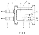
- FIG.3 is a front view of the water outlet from the cylinder head; and
- FIG.4 is an outline perspective view of a cooling system mounted on an internal combustion engine, as another embodiment according to the present invention.
- Hereinafter, an embodiment of the present invention will be described with reference to the drawings.
- Referring to FIG.1, Fig.2 and FIG.3, in the side surface of a
cylinder head 1 constructing an internal combustion engine is provided anoutlet 1a for coolant used to cool the interior of the internal combustion engine. Also, in the inside of thecylinder head 1 is formed asuction passage 1b to return the coolant into a water pump (coolant pumping means, not shown). - On the side surface of the
cylinder head 1 is mounted a water outlet 3 (coolant distributing means) through agasket 2 by means of bolts. - This water outlet (coolant distributing means) 3 has a
mating surface 3a mating with the side surface of thecylinder head 1 through thegasket 2. In the interior of thewater outlet 3 afeeding chamber 3c and a receivingchamber 3d are provided and respectively positioned above and below apartition 3b interposed therebetween. The upper portion of thisreceiving chamber 3d communicates with lower portion of thefeeding chamber 3c through anotch 3e (bubble introducing means) formed vertically in a groove shape in themating surface 3a. - Further, on the exterior wall of the
water outlet 3 is provided aradiator connector 4 communicating with the inside of thefeeding chamber 3c and forming the first path A. Although theradiator connector 4 in this embodiment is illustrated in the right side of thewater outlet 3 for the sake of convenience to clarify the interior structure of thewater outlet 3, theconnector 4 may be provided either on the left side or on the top of thewater outlet 3. - Also, on the exterior wall of the
water outlet 3 is provided aheater connector 5 communicating with theinside feeding chamber 3c, and further on the rear side of thewater outlet 3 is provided aheater return connector 6 communicating with the inside receivingchamber 3d. - The
radiator connector 4 is to be connected to a hose communicating with a radiator (not shown). The coolant is supplied from theradiator connector 4 through this hose to the radiator (heat radiating means), in which the coolant is cooled and returned to a water pump (not shown). The radiator is provided with a cap, which constructs a bubble removing portion to discharge bubbles within the coolant outside. - The
heater connector 5 is to be connected to a hose connected to a heater core (not shown). The coolant is supplied from theheater connector 5 through this hose to the heater core, from which the coolant is returned through a hose (not shown) to theheater return connector 6. - Namely, when a water pump (coolant pumping means, not shown) is operated on the condition that the
water outlet 3 is fixedly mounted on the side of thecylinder head 1 with the intervention of thegasket 2, the coolant is supplied from the water pump into thecylinder head 1 and cylinder block to cool the inside thereof. After cooling the internal combustion engine, the coolant is introduced from thecoolant outlet 1a of thecylinder head 1 into thefeeding chamber 3c of thewater outlet 3. Through the interior of thefeeding chamber 3c, a part of the coolant is fed from theradiator connector 4 constructing the first path A into the radiator (heat radiating means). The coolant is cooled in the radiator and simultaneously the bubbles contained in the coolant are drawn out of the cap (bubble removing portion) of the radiator. After that, the coolant is returned into the water pump (coolant pumping means). - Also, another part of the coolant is fed from the
feeding chamber 3c through theheater connector 5 into the heater core (not shown). The coolant is returned from the heater core through theheater return connector 6 into thereceiving chamber 3d of thewater outlet 3. Further, the coolant is returned from thereceiving chamber 3d through thesuction passage 1b formed inside thecylinder head 1 to the water pump (not shown). - As stated above, with regard to the coolant that is fed from the radiator connector through the first path A into the radiator (heat radiating means), the bubbles in the coolant are removed at the cap (bubble removing portion) of the radiator, and then the coolant is returned to the water pump. On the other hand, with regard to the coolant that is fed from the
heater connector 5 into the heater core (not shown) and returned through the second path B (thereturn connector 6, receivingchamber 3d andsuction passage 1b) into the water pump (not shown), if a part of the coolant is vaporized and bubbles are generated within the coolant, the coolant in case of the prior art may be returned into the water pump as containing the bubbles. However, in this embodiment, the bubbles within the coolant entered thereceiving chamber 3d of the second path B float up through the notch (bubble introducing portion) 3e formed in thewater outlet 3 into thefeeding chamber 3c. Further, the bubbles are carried from thefeeding chamber 3c through the first path A and removed out of the radiator cap. Accordingly, the bubbles are prevented from entering the water pump (coolant pumping means) without lowering its efficiency, so that the cooling performance of the cooling system may be improved. - Incidentally, in this embodiment the water outlet (coolant distributing means) 3 and the radiator with a cap (bubble removing portion, not shown) compose a coolant returning means.
- As described above, due to a simple structure in which the interior of a
water outlet 3 is divided into afeeding chamber 3c composing the first path A and a receivingchamber 3d composing the second path B and the receivingchamber 3d communicates with thefeeding chamber 3c through a notch (bubble introducing portion) 3e, the bubbles contained in the coolant flowing through the second path B is well introduced through thenotch 3e into thefeeding chamber 3c of the first path A. Then, the bubbles may be removed from the coolant and discharged out of the radiator cap in the first path A. - Now, referring to FIG.4 showing a schematic perspective view of another embodiment, a
water outlet 3 is fixedly mounted through a gasket on one side of acylinder head 1 composing an internal combustion engine. - On the top of the
water outlet 3 is provided aradiator connector 4, to which is connected a radiator passage 7 composing the first path A. Through the radiator passage 7 into a radiator (not shown) is fed a coolant, so that the bubbles in the coolant are drawn out at a cap (bubble removing portion, not shown) provided on the radiator. Then, the coolant is returned through aradiator return passage 8 composing the first path A into a water pump (coolant pumping means) 9. - Also, on one side of the
water outlet 3 is provided aheater connector 5 connected to aheater passage 10 having one end connected to aheater core 11. From theheater core 11 is extended aheater return passage 12, which is connected to asuction passage 13, which is further connected to thewater pump 9. The coolant from theheater core 11 is returned through theheater return passage 12 andsuction passage 13, both of which compose the second path B, into thewater pump 9. - In this embodiment, there is provided a bypass passage 14 (bubble introducing portion) that makes this
suction passage 13 communicate with the inside of thewater outlet 3. In the second path B, the bubbles contained in the coolant are carried through theheater return passage 12 into thesuction passage 13, from which the bubbles are introduced through thebypass passage 14 into thewater outlet 3. Then, the bubbles are carried through theradiator connector 4 into the radiator and removed at the radiator cap (bubble removing portion). - Accordingly, also in such a construction as the second embodiment, the bubbles in the coolant may be well removed by utilizing the cap (bubble removing portion) of the existing radiator (heat radiating means). Since no bubbles are transferred into the
water pump 9, the efficiency of thewater pump 9 is prevented from lowering and the cooling performance of the cooling system may be improved. - Having described the invention in detail and by reference to the preferred embodiment thereof, it will be apparent that other modifications and variations are possible without departing from the scope of the invention defined in the appended claims.
Claims (7)
- A cooling system for performing the cooling of an internal combustion engine by means of circulating coolant, comprising:a coolant pumping means for pumping said coolant; anda coolant returning means for removing bubbles included in said coolant and for returning the coolant without bubbles to said coolant pumping means.
- A cooling system as defined in claim 1, wherein said coolant returning means is a means for removing bubbles contained in the coolant after cooling said internal combustion engine and for returning the coolant to said coolant pumping means.
- A cooling system as defined in claim 1 or 2, wherein said coolant returning means comprises a first path for returning said coolant to said coolant pumping means through a bubble removing portion capable of removing the bubbles, and a second path for returning said coolant to said coolant pumping means not through said bubble removing portion; and in said second path is formed a bubble introducing portion capable of introducing said bubbles into said bubble removing portion through said first path.
- A cooling system as defined in claim 3, wherein said coolant returning means has a coolant distributing means comprising a feeding chamber for feeding the coolant after cooling said internal combustion engine into said first path and/or said second path; and a receiving chamber provided as a part of said second path under said feeding chamber for receiving the coolant fed into said second path from said feeding chamber; and said bubble introducing portion is a means for making the upper portion of said receiving chamber communicate with said feeding chamber.
- A cooling system as defined in claim 4, wherein said coolant distributing means has a mating surface with said internal combustion engine; said feeding and said receiving chamber are divided by a partition formed as a part of said mating surface; and said bubble introducing portion is a notch formed in said partition.
- A cooling system as defined in any one of claims 3 to 5, wherein said first path is provided with a heat radiating means for radiating the heat of said coolant; and said bubble removing portion is formed in said heat-radiating means.
- An internal combustion engine provided with said cooing system as defined in any one of claims 1 to 6.
Applications Claiming Priority (1)
| Application Number | Priority Date | Filing Date | Title |
|---|---|---|---|
| JP2004253639A JP4286197B2 (en) | 2004-08-31 | 2004-08-31 | Cooling device and internal combustion engine provided with the same |
Publications (2)
| Publication Number | Publication Date |
|---|---|
| EP1630378A1 true EP1630378A1 (en) | 2006-03-01 |
| EP1630378B1 EP1630378B1 (en) | 2008-06-11 |
Family
ID=35456888
Family Applications (1)
| Application Number | Title | Priority Date | Filing Date |
|---|---|---|---|
| EP05255089A Expired - Lifetime EP1630378B1 (en) | 2004-08-31 | 2005-08-17 | Cooling system and internal combustion engine with the cooling system |
Country Status (5)
| Country | Link |
|---|---|
| US (1) | US7308870B2 (en) |
| EP (1) | EP1630378B1 (en) |
| JP (1) | JP4286197B2 (en) |
| CN (1) | CN100520005C (en) |
| DE (1) | DE602005007436D1 (en) |
Families Citing this family (3)
| Publication number | Priority date | Publication date | Assignee | Title |
|---|---|---|---|---|
| KR101596700B1 (en) * | 2014-05-27 | 2016-02-23 | 현대자동차주식회사 | Sturucture for discharging air bubble of exhaust heat recovery device |
| JP6512290B2 (en) * | 2015-06-25 | 2019-05-15 | 日産自動車株式会社 | Casting apparatus and casting method |
| CN106658770A (en) * | 2016-12-27 | 2017-05-10 | 芜湖艾尔达科技有限责任公司 | Heating assembly |
Citations (3)
| Publication number | Priority date | Publication date | Assignee | Title |
|---|---|---|---|---|
| FR2317489A1 (en) * | 1975-07-11 | 1977-02-04 | Citroen Sa | Degasification of water of car engine cooling system - using swirl chamber with tangential inlet and outlet in secondary circuit to extract gas bubbles |
| US5666911A (en) * | 1995-10-13 | 1997-09-16 | Mercedes-Benz Ag | Cooling system for a liquid-cooled internal combustion engine |
| US6550431B1 (en) * | 1998-07-31 | 2003-04-22 | Volvo Lastvagnar Ab | Method and a device for degassing a cooling system for an internal combustion engine |
Family Cites Families (7)
| Publication number | Priority date | Publication date | Assignee | Title |
|---|---|---|---|---|
| US3384304A (en) * | 1967-04-03 | 1968-05-21 | Barlow Vapor Cooling Company | Ebullient cooling system for automotive gasoline engines with constant temperature passenger space heater |
| FR2514479B1 (en) * | 1981-10-13 | 1987-05-07 | Valeo | LIQUID CIRCULATION HEAT EXCHANGER, PARTICULARLY FOR A MOTOR VEHICLE |
| JP2950553B2 (en) * | 1989-09-26 | 1999-09-20 | 株式会社日本自動車部品総合研究所 | Internal combustion engine cooling system |
| US5092282A (en) * | 1990-06-21 | 1992-03-03 | Volkswagen Ag | Evaporation cooling system for an internal combustion engine |
| US5139082A (en) * | 1990-08-31 | 1992-08-18 | Teledyne Industries, Inc. | Cooling system for a liquid cooled engine |
| US5255635A (en) * | 1990-12-17 | 1993-10-26 | Volkswagen Ag | Evaporative cooling system for an internal combustion engine having a coolant equalizing tank |
| US5385123A (en) * | 1993-10-08 | 1995-01-31 | Evans; John W. | Segregated cooling chambers for aqueous reverse-flow engine cooling systems |
-
2004
- 2004-08-31 JP JP2004253639A patent/JP4286197B2/en not_active Expired - Lifetime
-
2005
- 2005-08-15 US US11/203,102 patent/US7308870B2/en not_active Expired - Lifetime
- 2005-08-17 EP EP05255089A patent/EP1630378B1/en not_active Expired - Lifetime
- 2005-08-17 DE DE602005007436T patent/DE602005007436D1/en not_active Expired - Lifetime
- 2005-08-25 CN CNB2005100969035A patent/CN100520005C/en not_active Expired - Lifetime
Patent Citations (3)
| Publication number | Priority date | Publication date | Assignee | Title |
|---|---|---|---|---|
| FR2317489A1 (en) * | 1975-07-11 | 1977-02-04 | Citroen Sa | Degasification of water of car engine cooling system - using swirl chamber with tangential inlet and outlet in secondary circuit to extract gas bubbles |
| US5666911A (en) * | 1995-10-13 | 1997-09-16 | Mercedes-Benz Ag | Cooling system for a liquid-cooled internal combustion engine |
| US6550431B1 (en) * | 1998-07-31 | 2003-04-22 | Volvo Lastvagnar Ab | Method and a device for degassing a cooling system for an internal combustion engine |
Also Published As
| Publication number | Publication date |
|---|---|
| US20060042568A1 (en) | 2006-03-02 |
| JP4286197B2 (en) | 2009-06-24 |
| CN1743648A (en) | 2006-03-08 |
| DE602005007436D1 (en) | 2008-07-24 |
| CN100520005C (en) | 2009-07-29 |
| US7308870B2 (en) | 2007-12-18 |
| EP1630378B1 (en) | 2008-06-11 |
| JP2006070759A (en) | 2006-03-16 |
Similar Documents
| Publication | Publication Date | Title |
|---|---|---|
| US6216646B1 (en) | Deaeration bottle for liquid cooling systems for automotive vehicle engines | |
| US9618282B2 (en) | Radiator for vehicle | |
| US11230962B2 (en) | Reservoir tank with integrated ejector | |
| CN100398804C (en) | Water cooling device for longitudenal multiple cylinder engine | |
| GB2561599A (en) | Cooling system | |
| KR101416419B1 (en) | Radiator for vehicle | |
| US7308870B2 (en) | Coolant distributing means for an internal combustion engine | |
| CN110886645B (en) | Internal combustion engine body | |
| US20090235878A1 (en) | Cooling apparatus of v-type internal combustion engine | |
| US8016206B2 (en) | Vehicle air conditioning system and automobile having the vehicle air conditioning system | |
| US6179043B1 (en) | Heavy vehicle radiator with center-mounted hydraulic cooling fan motor and hydraulic motor oil cooler | |
| EP3769992B1 (en) | Work vehicle | |
| JP2000345838A (en) | Water-cooled internal combustion engine cooling system | |
| US20170254252A1 (en) | Engine having water jacket | |
| EP1765613A2 (en) | A cooling system of an amphibious vehicle | |
| US7886710B2 (en) | Oil filter unit and motorcycle including the oil filter unit | |
| CA1091112A (en) | Radiator top tank with plural sump lines | |
| JP6040658B2 (en) | Cooling device for internal combustion engine | |
| KR100534895B1 (en) | Structure of radiator for automobile | |
| US11149679B2 (en) | Internal combustion engine with top-down cooling | |
| KR100692760B1 (en) | V engine cooling system | |
| JP2003222022A (en) | Engine cooling structure | |
| CN214008023U (en) | Automobile motor speed reducer | |
| JP2006160212A (en) | Fuel cell vehicle cooling structure | |
| KR101588791B1 (en) | Radiator for vehicle |
Legal Events
| Date | Code | Title | Description |
|---|---|---|---|
| PUAI | Public reference made under article 153(3) epc to a published international application that has entered the european phase |
Free format text: ORIGINAL CODE: 0009012 |
|
| AK | Designated contracting states |
Kind code of ref document: A1 Designated state(s): AT BE BG CH CY CZ DE DK EE ES FI FR GB GR HU IE IS IT LI LT LU LV MC NL PL PT RO SE SI SK TR |
|
| AX | Request for extension of the european patent |
Extension state: AL BA HR MK YU |
|
| 17P | Request for examination filed |
Effective date: 20060404 |
|
| AKX | Designation fees paid |
Designated state(s): DE FR GB |
|
| GRAP | Despatch of communication of intention to grant a patent |
Free format text: ORIGINAL CODE: EPIDOSNIGR1 |
|
| GRAS | Grant fee paid |
Free format text: ORIGINAL CODE: EPIDOSNIGR3 |
|
| GRAA | (expected) grant |
Free format text: ORIGINAL CODE: 0009210 |
|
| AK | Designated contracting states |
Kind code of ref document: B1 Designated state(s): DE FR GB |
|
| REG | Reference to a national code |
Ref country code: GB Ref legal event code: FG4D |
|
| REF | Corresponds to: |
Ref document number: 602005007436 Country of ref document: DE Date of ref document: 20080724 Kind code of ref document: P |
|
| PLBE | No opposition filed within time limit |
Free format text: ORIGINAL CODE: 0009261 |
|
| STAA | Information on the status of an ep patent application or granted ep patent |
Free format text: STATUS: NO OPPOSITION FILED WITHIN TIME LIMIT |
|
| 26N | No opposition filed |
Effective date: 20090312 |
|
| REG | Reference to a national code |
Ref country code: FR Ref legal event code: PLFP Year of fee payment: 12 |
|
| REG | Reference to a national code |
Ref country code: FR Ref legal event code: PLFP Year of fee payment: 13 |
|
| REG | Reference to a national code |
Ref country code: FR Ref legal event code: PLFP Year of fee payment: 14 |
|
| REG | Reference to a national code |
Ref country code: DE Ref legal event code: R081 Ref document number: 602005007436 Country of ref document: DE Owner name: NISSAN MOTOR CO., LTD., YOKOHAMA-SHI, JP Free format text: FORMER OWNERS: NISSAN MOTOR CO., LTD., YOKOHAMA-SHI, KANAGAWA-KEN, JP; AICHI MACHINE INDUSTRY CO., LTD., NAGOYA-SHI, AICHI, JP Ref country code: DE Ref legal event code: R082 Ref document number: 602005007436 Country of ref document: DE Representative=s name: GRUENECKER PATENT- UND RECHTSANWAELTE PARTG MB, DE |
|
| REG | Reference to a national code |
Ref country code: GB Ref legal event code: 732E Free format text: REGISTERED BETWEEN 20220630 AND 20220706 |
|
| PGFP | Annual fee paid to national office [announced via postgrant information from national office to epo] |
Ref country code: DE Payment date: 20240723 Year of fee payment: 20 |
|
| PGFP | Annual fee paid to national office [announced via postgrant information from national office to epo] |
Ref country code: GB Payment date: 20240723 Year of fee payment: 20 |
|
| PGFP | Annual fee paid to national office [announced via postgrant information from national office to epo] |
Ref country code: FR Payment date: 20240723 Year of fee payment: 20 |
|
| REG | Reference to a national code |
Ref country code: DE Ref legal event code: R071 Ref document number: 602005007436 Country of ref document: DE |
|
| REG | Reference to a national code |
Ref country code: GB Ref legal event code: PE20 Expiry date: 20250816 |