EP1630331B1 - Biaxiales Scharnier für tragbaren Geräte und Montagevorrichtung - Google Patents
Biaxiales Scharnier für tragbaren Geräte und Montagevorrichtung Download PDFInfo
- Publication number
- EP1630331B1 EP1630331B1 EP05018601A EP05018601A EP1630331B1 EP 1630331 B1 EP1630331 B1 EP 1630331B1 EP 05018601 A EP05018601 A EP 05018601A EP 05018601 A EP05018601 A EP 05018601A EP 1630331 B1 EP1630331 B1 EP 1630331B1
- Authority
- EP
- European Patent Office
- Prior art keywords
- hinge
- center shaft
- biaxial
- fastening
- module
- Prior art date
- Legal status (The legal status is an assumption and is not a legal conclusion. Google has not performed a legal analysis and makes no representation as to the accuracy of the status listed.)
- Expired - Lifetime
Links
Images


Classifications
-
- H—ELECTRICITY
- H04—ELECTRIC COMMUNICATION TECHNIQUE
- H04B—TRANSMISSION
- H04B1/00—Details of transmission systems, not covered by a single one of groups H04B3/00 - H04B13/00; Details of transmission systems not characterised by the medium used for transmission
- H04B1/38—Transceivers, i.e. devices in which transmitter and receiver form a structural unit and in which at least one part is used for functions of transmitting and receiving
-
- H—ELECTRICITY
- H04—ELECTRIC COMMUNICATION TECHNIQUE
- H04M—TELEPHONIC COMMUNICATION
- H04M1/00—Substation equipment, e.g. for use by subscribers
- H04M1/02—Constructional features of telephone sets
- H04M1/0202—Portable telephone sets, e.g. cordless phones, mobile phones or bar type handsets
- H04M1/0206—Portable telephones comprising a plurality of mechanically joined movable body parts, e.g. hinged housings
- H04M1/0208—Portable telephones comprising a plurality of mechanically joined movable body parts, e.g. hinged housings characterized by the relative motions of the body parts
- H04M1/0214—Foldable telephones, i.e. with body parts pivoting to an open position around an axis parallel to the plane they define in closed position
- H04M1/0222—Foldable in two directions, i.e. using a two degree of freedom hinge
-
- E—FIXED CONSTRUCTIONS
- E05—LOCKS; KEYS; WINDOW OR DOOR FITTINGS; SAFES
- E05D—HINGES OR SUSPENSION DEVICES FOR DOORS, WINDOWS OR WINGS
- E05D3/00—Hinges with pins
- E05D3/06—Hinges with pins with two or more pins
- E05D3/10—Hinges with pins with two or more pins with non-parallel pins
-
- E—FIXED CONSTRUCTIONS
- E05—LOCKS; KEYS; WINDOW OR DOOR FITTINGS; SAFES
- E05Y—INDEXING SCHEME ASSOCIATED WITH SUBCLASSES E05D AND E05F, RELATING TO CONSTRUCTION ELEMENTS, ELECTRIC CONTROL, POWER SUPPLY, POWER SIGNAL OR TRANSMISSION, USER INTERFACES, MOUNTING OR COUPLING, DETAILS, ACCESSORIES, AUXILIARY OPERATIONS NOT OTHERWISE PROVIDED FOR, APPLICATION THEREOF
- E05Y2999/00—Subject-matter not otherwise provided for in this subclass
-
- H—ELECTRICITY
- H04—ELECTRIC COMMUNICATION TECHNIQUE
- H04M—TELEPHONIC COMMUNICATION
- H04M2250/00—Details of telephonic subscriber devices
- H04M2250/52—Details of telephonic subscriber devices including functional features of a camera
Definitions
- the present invention relates to digital communication apparatuses, such as cellular phones, PDAs (personal digital assistants), HHPs (hand held phones), camera phones, game phones, Internet phones, and the like. More particularly, the present invention relates to a biaxial hinge device for a mobile terminal and a mounting mechanism thereof.
- mobile terminals are electronic devices capable of being carried by a user for wireless communication.
- a mobile terminal tends to be more compact, thin, and lightweight, to facilitate terminal portability.
- the terminal incorporates multimedia technologies providing a large variety of functions.
- a future mobile terminal may be compact, lightweight, multifunctional, and multipurpose, and be developed to adapt itself to various multimedia or internet environments.
- the mobile terminal is an electronic device commonly used by consumers all over the world, and has become an essential part of everyday life.
- mobile terminals There are several types of appearances for mobile terminals, such as a bar-type mobile terminal, a flip-type mobile terminal, and a folder-type mobile terminal. There also are two types of mobile terminals according to a carrying position or carrying fashion, including a necklace-type mobile terminal, and a wrist-type mobile terminal. In addition, there are three types of mobile terminals according to an operation manner of a folder, including a swing-type mobile terminal, a sliding-type mobile terminal, and a swivel-type mobile terminal. The above described mobile terminals are known by those skilled in the art.
- a conventional mobile terminal has been adapted to carry out high-speed data communications, as well as voice communications.
- various services capable of using wireless communication technology for transmitting and receiving data at a high speed are provided.
- a conventional mobile terminal has been developed to transmit an image signal using a camera lens mounted to the portable terminal.
- the portable terminal is provided with an embedded or external camera lens module, so that a user can communicate an image to another terminal or to photograph a desired object.
- the conventional flip-type mobile terminal or folder-type mobile terminal adopts a construction of two housings rotatably connected to each other by one hinge device, it is inconvenient for a user to see information displayed on a display device of the mobile terminal.
- an object of the present invention is to provide a biaxial hinge device for a mobile terminal and a mounting mechanism thereof.
- Another object of the present invention is to provide a biaxial hinge device for a mobile terminal and a mounting mechanism thereof, in which a folder may be folded and unfolded in two different directions by means of first and second hinge axes to improve convenient use by a user.
- Still another object of the present invention is to provide a biaxial hinge device for a mobile terminal and a mounting mechanism thereof, in which a user may conveniently see information displayed on a display device and conveniently manipulate input keys.
- a biaxial hinge device for a mobile terminal includes a body and a folder folded on or unfolded from the body.
- the biaxial hinge device includes a first hinge module for rotatably connecting the folder to the body around a first hinge axis, and a second hinge module for rotatably connecting the folder to the body around a second hinge axis that is spaced apart form the first hinge axis and disposed in a direction substantially perpendicular to the first hinge axis.
- a portion of the second hinge module is inserted in the first hinge module, thereby allowing the second hinge module to move both independently of and in cooperation with the first hinge module.
- a biaxial hinge device for a mobile terminal includes a body and a folder folded on or unfolded from the body.
- the biaxial hinge device includes an auxiliary center shaft for rotatably connecting the folder to the body around a first hinge axis.
- An outer periphery of the auxiliary center shaft is formed with a first receiving groove.
- a second main center shaft rotatably connects the folder to the body around a second hinge axis that is spaced apart form the first hinge axis and disposed in a direction substantially perpendicular to the first hinge axis.
- An outer periphery of the second main center shaft is formed with a second receiving groove, and the second main center shaft receives a portion of the auxiliary center shaft in cooperation with each other.
- a mounting mechanism of a biaxial hinge device for a mobile terminal includes a side arm provided to a body, and a biaxial hinge module having a first hinge axis and a second hinge axis spaced apart form the first hinge axis and disposed in a direction substantially perpendicular to the first hinge axis.
- a side hinge housing accommodating the biaxial hinge module and restricting movement of the side arm rotates around the first hinge axis.
- First fastening means restricts the biaxial hinge module to the side arm.
- Second fastening means restricts the biaxial hinge module to the side hinge housing.
- a mobile tenninal employing a biaxial hinge device according to an exemplary embodiment of the present invention will be described, prior to description of the biaxial hinge device and a mounting mechanism according to an exemplary embodiment of the present invention.
- the mobile terminal includes a body and a folder foldable around a first hinge shaft in a transverse direction or a second hinge shaft in a vertical direction, so that a user may selectively use a folding position of the folder to input data or view the data displayed on a screen.
- the mobile terminal employing the biaxial hinge device includes a body 100, a first hinge axis A1 transversely disposed in the body 100, a second hinge axis A2 vertically disposed in the body 100, and a folder 200 selectively rotating around the first and second hinge axes A1 and A2.
- the folder 200 is connected to the body 100 to rotate around the first hinge axis A1 so that the folder moves close to or far apart from the body, with the folder being opposite to the body.
- the folder 200 is connected to the body 100 to rotate around the second hinge axis A2 so that the folder moves close to or far apart from the body, with the folder being opposite to the body.
- the body 100 has a plate box shape with a rectangular upper surface 101 and a rectangular lower surface (not shown), and a shape of the folder 200 preferably corresponds to the shape of the body 100.
- the body 100 shown in FIG. 1 preferably extends in a vertical direction rather than a transverse direction.
- the first hinge axis A1 extends along an upper end of the body 100
- the second hinge axis A2 extends along one side of the body 100.
- the first and second hinge axes A1 and A2 are vertically spaced apart from each other.
- the body 100 includes a pair of side arms 510 and 520 integrally formed on the upper surface 101 towards the upper end of the body.
- a rotatable lens housing 400 is disposed between the pair of the side arms 510 and 520, with a camera lens 410 thereof being exposed.
- a biaxial hinge device (housed within the side hinge housing 300 shown) is rotatably mounted adjacent to the side arm 510.
- a keypad 110 having a plurality of input keys is disposed on the upper surface 101 of the body.
- a slot 114 is linearly elongated along an edge 103 of the upper surface 101. The slot 114 prevents interference by the rotation of the folder 200.
- the side hinge housing 300 is provided with a biaxial hinge device as described hereinafter.
- the folder 200 has a flat upper surface 201 and a lower surface 202.
- a loudspeaker 210 and a display 212 adjacent to the loudspeaker 210 are disposed on the lower surface 202.
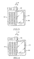
- the mobile terminal may be utilized in the state shown in FIG. 1 or the state shown in FIG. 4 , depending upon selection of the user.
- FIG 1 shows a calling mode
- FIG. 4 shows a seeing and hearing mode for PDA, TV or video.
- a rotating angle of the folder 200 around the first hinge axis A1 is preferably within a range from about 130° to about 160°, and FIG. 2 shows a fully opened state of the folder 200.
- a rotating angle of the folder 200 around the second hinge axis A2 is preferably about 180°, and FIG. 4 shows a fully opened state of the folder 200.
- the mounting mechanism includes the side arm 510 disposed at a desired position of the body for mounting the biaxial hinge device M, which provides the first and second hinge axes and rotates around the first hinge axis A1, to the side arm 510 of the body, the side hinge housing 300 accommodating the biaxial hinge device M and restricting movement of the side arm 510 rotating around the first hinge axis, and fastening means for fixing the side hinge housing 300 to the side arm 510.
- the fastening means includes first fastening means provided at one side of the side ann 510, and second fastening means provided to the other side of the side hinge housing 300.
- the first fastening means has a first fastening member 514 inserted and fixed to a first recess 511 formed on an outer surface of the side arm 510 by means of a screw (not shown), a first fastening boss 516 formed on an inner surface of the side arm 510, a first fastening groove 312 formed on an outer surface of the main hinge housing 310 of the biaxial hinge device for accommodating the first fastening boss 516, and first fastening holes 314, 512 and 515 for restraining the first fastening member 514, the side arm 510, and the main hinge housing 310 by fastening fastener, such as a screw (not shown), thereto in the axial direction of the first hinge axis.
- the first fastening holes 314, 512 and 515 are coaxially formed on the surface of the main hinge housing 310, respectively.
- the first fastening member 514 is preferably a plate element, and is formed with a first engaging groove 514a of a desired shape on the outer surface of the first fastening member.
- the first recess 511 is formed with a first engaging boss 513 corresponding to the first engaging groove 514a on an inner wall of the first recess 511.
- the first engaging groove 514a is recessed in a center direction of the first fastening member 514, and the first engaging boss 513 protrudes in a center direction of the first recess 511.
- the first fastening member 514 is fixed in the axial direction of the first hinge axis by fastening a screw (not shown) to the fastening hole 515 and coupling the first engaging boss 513 with the first engaging groove 514a.
- the first fastening boss 516 protrudes from the inner surface of the side arm 510, and is formed in a shape of three-leafed clover.
- the first fastening groove 312 has a shape corresponding to the first fastening boss 516.
- the second fastening means fixes the biaxial hinge device M to the side hinge housing 300 in the axial direction of the first hinge axis.
- the second fastening means includes second fixing bosses 323 formed at the other end of the main hinge shaft 320 of the biaxial hinge device, fixing holes 306 formed on the other end surface of the side hinge housing 300 for receiving the fixing bosses 323, and a second fastening member 308 fastened with the main hinge shaft 320 at the other side of the side hinge arm by means of a screw (now shown).
- the second fastening member 308 is preferably a plate.
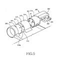
- the side hinge housing 300 is formed with an assembling opening 304 of a desired shape for accommodating a second hinge module (360 and 370 in FIG. 7 ) of the biaxial hinge device M.
- FIGs. 5 and 6 show an exposed state of a fastening piece 370 of the biaxial hinge device assembled to the side hinge housing 300.
- a structural reinforcing portion 302 is provided around the assembling opening 304 of the side hinge housing to prevent the side hinge housing from being cracked by rotation of the second hinge module of the biaxial hinge device.
- the biaxial hinge device M according to the present invention is accommodated in the side hinge housing 300, and includes a first hinge module providing the first hinge axis and a second hinge module providing the second hinge axis.
- the first and second hinge modules are vertically disposed to operate in cooperation with each other, the description of which will be given hereinafter.
- the first hinge module includes a main hinge housing 310 fastened to the side arm 510, a first main center shaft 320 fastened to the side hinge housing 300 in which rotation of the first main center shaft is restricted by the main hinge housing 310, an auxiliary center shaft 330 accommodated in the first main center shaft 320, and hinge members sequentially inserted into the auxiliary center shaft 330 for providing opening and closing forces in cooperation with these hinge members (that is, hinge spring 335, a hinge shaft 340 and a hinge cam 350).
- the first main center shaft 320 has a large diameter portion 321, and a small diameter portion 322 extending from the large diameter portion 321.
- the large diameter portion 321 is provided with a plurality of fastening bosses 323 so that it is restricted by the side hinge housing 300, and also with a cutaway portion 324 of a desired shape for accommodating the second main center shaft 360 of the second hinge module.
- the first main center shaft 320 is formed with a first opening 325 perforating a center portion thereof for accommodating the auxiliary center shaft 330.
- the large diameter portion 321 is formed with a second opening 326 for accommodating the second main center shaft 360 of the second hinge module.
- the first opening 325 is continuously elongated in the axial direction of the first hinge axis
- the second opening 326 is continuously elongated in the axial direction of the second hinge axis.
- the first opening 325 perforates a rotational center axis of the first main center shaft 320
- the second opening 326 is spaced apart from the first opening in a direction substantially perpendicular to the elongated direction of the first opening 325.
- the first and second openings 325 and 326 are in communication with each other.
- the auxiliary center shaft 330 has a large diameter portion 331, and a small diameter portion 332 extending from a center of the large diameter portion 331.
- the hinge spring 335, the hinge shaft 340, and the hinge cam 350 are sequentially inserted in the small diameter portion 332.
- the construction and operation of the hinge spring 335, hinge shaft 340 and hinge cam 350 are widely known in the art, the detailed description of which is omitted herein.
- the second hinge module has a second main center shaft 360, and a fastening piece 370 fastened to a stepped portion of the second main center shaft 360.
- the second main center shaft 360 has a cam portion 361 inserted in the second opening 326 for camming the large diameter portion 331 of the auxiliary center shaft, and a fastening shaft 362 extending from the cam portion 361 and fastened to the fastening piece by means of a fastener, such as a screw.
- the fastening shaft 362 is provided at an end portion thereof with a D-shaped cut portion 363 to engage the fastening piece 370.
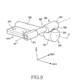
- the auxiliary center shaft 330 has the large diameter portion 331 perforating the first hinge shaft, and the small diameter portion 332 extending from one side of the large diameter portion 331, as shown in FIG. 9 . Since the large diameter portion 331 and the small diameter portion 332 have a circular cross section, a stepped portion is provided therebetween.
- the small diameter portion 332 linearly extends and has the D-shaped cut portion 333 at the one end portion thereof ( FIG. 8 ).
- the large diameter portion 331 is formed with a first receiving groove 334 at an outer periphery thereof.
- the first receiving groove 334 receives a portion of the outer periphery of the cam portion 361 of the second main center shaft 360 according to the rotation of the second main center shaft.
- the first receiving groove 334 has a convex round surface corresponding to the outer periphery of the cam portion 361.
- the second main center shaft 360 has the cam portion 361 disposed along the second hinge axis, and the fastening piece 370 formed at the stepped portion of the second main center shaft 360 and secured to the folder by means of a fastener, such as a screw.
- the second main center shaft 360 and the fastening piece 370 are vertically opposite to each other.
- the fastening piece 370 is a plate.
- the fastening piece 370 extends from the second main center shaft 360 substantially parallel to the small diameter portion 332 of the auxiliary center shaft 330 along the first hinge axis.
- the second main center shaft 360 has a cam portion 361 slidingly contacting the auxiliary center shaft 330, and a fastening shaft 362 linearly extending from one side of the cam portion 361.
- the cam portion 361 is formed with a second receiving groove 363 of a desired shape at the outer periphery thereof.
- the second receiving groove 363 receives a portion of the outer periphery of the large diameter portion 331.
- the second receiving groove 363 has a round bottom corresponding to the outer periphery of large diameter portion 331.
- the fastening shaft 362 is coupled to the stepped portion 371 of the fastening piece 370.
- the fastening piece 370 is formed with a plurality of fastening holes 372, and is fastened to the folder by means of a fastener, such as a screw (not shown).
- the cam portion 361 and the fastening shaft 362 are linearly and cylindrically extending.
- a diametric center of the cam portion is preferably offset from a diametric center of the fastening shaft.
- the diametric center of the cam portion 361 does not coincide with that of the fastening shaft 362.
- the auxiliary center shaft 330 and the second main center shaft 360 shown in FIG. 9 correspond to the state shown in FIG. 1 .
- the auxiliary center shaft 330 and the second main center shaft 360 shown in FIG. 10 correspond to the state shown in FIG. 3 .
- the auxiliary center shaft 330 and the second main center shaft 360 shown in FIG. 11 correspond to the state shown in FIG. 2 .
- the exemplary embodiment of the present invention opens the folder in two directions so that the user may conveniently see the information or input the data in relation to the conventional device.
Landscapes
- Engineering & Computer Science (AREA)
- Signal Processing (AREA)
- Computer Networks & Wireless Communication (AREA)
- Telephone Set Structure (AREA)
- Pivots And Pivotal Connections (AREA)
Claims (17)
- Biaxiale Scharniervorrichtung für ein mobiles Endgerät, das einen Körper (100) und eine Klappe (200), die auf den Körper geklappt wird oder von dem Körper (100) weggeklappt wird, umfasst, die biaxiale Scharniervorrichtung aufweisend:ein erstes Scharniermodul, das mit dem Körper (100) mit Hilfe einer Montagevorrichtung verbunden ist, zum drehbaren Verbinden des Körpers (100) mit der Klappe (200) um eine erste Scharnierachse (A1); undein zweites Scharniermodul, das mit der Klappe (200) verbunden ist, zum drehbaren Verbinden der Klappe (200) mit dem Körper (100) um eine zweite Scharnierachse (A2), wobei ein Abschnitt des zweiten Scharniermoduls in das erste Scharniermodul eingeführt ist und der zweite Scharniermodul gleitet in dem ersten Scharniermodul um miteinander zusammenzuarbeiten;dadurch gekennzeichnet, dass
das erste Scharniermodul aus einem ersten Hauptmittelschaft (320) und einem Hilfsmittelschaft (330) aufgebaut ist, wobei der Hilfsmittelschaft (330) einen Abschnitt (331) mit einem großen Durchmesser umfasst, der mit einer ersten aufnehmenden Nut (334) auf einem äußeren Umfang darauf ausgebildet ist; und
das zweite Scharniermodul aus einem zweiten Hauptmittelschaft (360) aufgebaut ist, der in dem ersten Scharniermodul untergebracht ist, wobei der zweite Hauptmittelschaft (360) einen Nockenabschnitt (361) aufweist, der mit einer zweiten empfangenden Nut (363) auf einem äußeren Umfang darauf ausgebildet ist, wobei die zweite Scharnierachse (A2), die von der ersten Scharnierachse (A1) beabstandet ist und in einer im Wesentlichen senkrechten Richtung zu der ersten Scharnierachse (A1) angeordnet ist. - Biaxiale Scharniervorrichtung nach Anspruch 1, wobei das erste Scharniermodul umfasst
ein Hauptscharniergehäuse (310), das an dem Körper (100) befestigt ist,
wobei der erste Hauptmittelschaft (320) in das Hauptscharniergehäuse (300) in einer axialen Richtung der ersten Scharnierachse (A1) eingeführt ist;
ein Hilfsmittelschaft (330), der in dem ersten Hauptmittelschaft (320) eingeführt ist; und
Scharnierbauteile (335, 340, 350) sind nacheinander um die erste Scharnierachse (A1) auf dem Hilfsmittelschaft (330) eingeführt zum Bereitstellen von Öffnungs- und Schließkräften. - Biaxiale Scharniervorrichtung nach Anspruch 2, wobei der erste Hauptmittelschaft (320) umfasst
einen Abschnitt (321) mit großem Durchmesser, der einen ausgenommenen Abschnitt (324) aufweist, der kreisförmig auf einem äußeren Umfang des ersten Hauptmittelschafts (320) in einem gewünschten Winkel ausgebildet ist, wobei eine erste Öffnung (325) entlang der ersten Scharnierachse (A1) langgestreckt ist, und wobei eine zweite Öffnung (326) vertikal von der ersten Öffnung (325) des ausgenommenen Abschnitts (324) langgestreckt ist; und
einen Abschnitt (322) mit kleinem Durchmesser, der sich koaxial von dem Abschnitt (321) mit großem Durchmesser erstreckt. - Biaxiale Scharniervorrichtung nach Anspruch 3, wobei
die erste und die zweite Öffnung (325, 326) miteinander kommunizieren. - Biaxiale Scharniervorrichtung nach Anspruch 2, wobei der Hilfsmittelschaft (330) aufweist
einen Abschnitt (332) mit kleinem Durchmesser, der sich gerade und koaxial von dem Abschnitt (331) mit großem Durchmesser erstreckt, zum Empfangen der Scharnierbauteile (335, 340, 350) und der einen im Wesentlichen D-förmigen ausgenommenen Ausschnitt (333) in der Nähe des einen Endes davon aufweist. - Biaxiale Scharnienvorrichtung nach Anspruch 2, wobei die Scharnierbauteile aufweisen
eine Scharniernocke (350), die in dem Hauptscharniergehäuse (310) aufgenommen ist;
einen Scharnierschaft (340), der gegenüber der Scharniernocke (350) angeordnet ist und Nockenoperationen durchführt; und
eine Scharnierfeder (335), die die Scharniernocke (350) und den Scharnierschaft (340) eng kontaktiert. - Biaxiale Scharniervorrichtung nach Anspruch 1, wobei das zweite Scharniermodul weiterhin umfasst
ein Befestigungsteil (370), das an einem Endabschnitt des zweiten Hauptmittelschafts (360) befestigt ist. - Biaxiale Scharniervorrichtung nach Anspruch 7, wobei der zweite Hauptmittelschaft (360) weiterhin umfasst
einen Befestigungschaft (362), der gerade und aus einem Teil geformt sich von einer Seite des Nockenabschnitts (361) erstreckt; und
der Nockenabschnitt (361) gleitend das erste Scharniermodul kontaktiert. - Biaxiale Scharniervorrichtung nach Anspruch 8, wobei
eine diametrale Mitte des Nockenabschnitts (361) so von einer diametralen Mitte des Befestigungsschafts (362) versetzt ist, dass die diametralen Mitten des Nockenabschnitts (361) und des Befestigungsschafts (362) nicht axial ausgerichtet sind. - Biaxiale Scharniervorrichtung nach Anspruch 7, wobei
das Befestigungsteil (370) mit der Klappe (200) verbunden ist. - Biaxiale Scharniervorrichtung nach Anspruch 1, wobei
die erste aufnehmende Nut (334) einen gewünschten Bereich des äußeren Umfangs des zweiten Hauptmittelschafts (360) beherbergt, und die zweite aufnehmende Nut (363) einen gewünschten Bereich des äußeren Umfangs des Hilfsmittelschafts (330) beherbergt gemäß einer Drehung des Hilfsmittelschafts (330) und des zweiten Hauptmittelschafts (360). - Biaxiale Scharniervorrichtung nach Anspruch 1, wobei
die erste und die zweite aufnehmende Nut (334, 363) mit einer runden Bodenoberfläche ausgebildet sind. - Biaxiale Scharniervorrichtung nach Anspruch 1, wobei die Montagevorrichtung aufweist:einen Seitenarm (510), der mit dem Körper (100) verbunden ist;ein biaxiales Scharniermodul (M), das durch die erste Scharnierachse (A1) und die zweite Scharnierachse (A2), die von der ersten Scharnierachse (A1) beabstandet ist, ausgebildet ist, und auch die zweite Scharnierachse (A2) ist in einer Richtung im Wesentlichen senkrecht zu der ersten Scharnierachse (A1) angeordnet;ein Seitenscharniergehäuse (300), das das biaxiale Scharniermodul (M) beherbergt und eine Bewegung des Seitenarms (510), der um die erste Scharnierachse (A1) rotiert, begrenzt;erste Befestigungsmittel zum Sichern des biaxialen Scharniermoduls (M) an dem Seitenarm (510); undzweite Befestigungsmittel zum Sichern des biaxialen Scharniermoduls (M) an dem Seitenscharniergehäuse (300).
- Montagevorrichtung nach Anspruch 13, wobei
das Seitenscharniergehäuse (300) mit einer Zusammenbauöffnung (304) ausgebildet ist. - Montagevorrichtung nach Anspruch 14, wobei
ein struktureller Verstärkungsabschnitt (302) um die Zusammenbauöffnung (304) bereitgestellt ist. - Montagevorrichtung nach Anspruch 13, wobei die ersten Befestigungsmittel umfassen
eine erste Aussparung (511), die auf einer äußeren Oberfläche des Seitenarms (510) ausgebildet ist;
ein erstes Befestigungsbauteil (514), das an der ersten Aussparung (511) in einer axialen Richtung der ersten Scharnierachse (A1) durch einen Befestiger befestigt ist;
ein erster Befestigungsvorsprung (516), der an einer inneren Oberfläche des Seitenarms 510 ausgebildet ist; und
eine erste Befestigungsnut (312), die an einer äußeren Oberfläche der biaxialen Scharniervorrichtung ausgebildet ist, zum Verbinden mit dem ersten Befestigungsvorsprung (516). - Montagevorrichtung nach Anspruch 16, wobei das erste Befestigungsbauteil (514) eine Platte ist.
Applications Claiming Priority (1)
| Application Number | Priority Date | Filing Date | Title |
|---|---|---|---|
| KR1020040068217A KR100640395B1 (ko) | 2004-08-28 | 2004-08-28 | 휴대 단말기의 이축 힌지 장치 및 그의 장착 메카니즘 |
Publications (3)
| Publication Number | Publication Date |
|---|---|
| EP1630331A2 EP1630331A2 (de) | 2006-03-01 |
| EP1630331A3 EP1630331A3 (de) | 2006-06-14 |
| EP1630331B1 true EP1630331B1 (de) | 2010-03-31 |
Family
ID=36093896
Family Applications (1)
| Application Number | Title | Priority Date | Filing Date |
|---|---|---|---|
| EP05018601A Expired - Lifetime EP1630331B1 (de) | 2004-08-28 | 2005-08-26 | Biaxiales Scharnier für tragbaren Geräte und Montagevorrichtung |
Country Status (5)
| Country | Link |
|---|---|
| US (1) | US7844050B2 (de) |
| EP (1) | EP1630331B1 (de) |
| KR (1) | KR100640395B1 (de) |
| CN (1) | CN100479638C (de) |
| DE (1) | DE602005020223D1 (de) |
Families Citing this family (18)
| Publication number | Priority date | Publication date | Assignee | Title |
|---|---|---|---|---|
| US7484268B2 (en) * | 2004-09-17 | 2009-02-03 | Samsung Electronics Co., Ltd. | Hinge device and portable terminal having the same |
| US7832055B2 (en) * | 2004-12-30 | 2010-11-16 | Sony Ericsson Mobile Communications Ab | Hinge |
| US9152238B2 (en) * | 2005-08-01 | 2015-10-06 | Wai-Lin Maw | Asymmetric shuffle keyboard |
| US7958602B2 (en) * | 2006-11-06 | 2011-06-14 | Mitsubishi Steel Mfg. Co., Ltd. | Hinge mechanism |
| KR100842529B1 (ko) | 2007-02-22 | 2008-07-01 | 삼성전자주식회사 | 힌지 장치를 구비하는 휴대용 단말기 |
| KR100769035B1 (ko) * | 2007-04-27 | 2007-10-22 | (주)쉘-라인 | 힌지장치 |
| US20100184490A1 (en) * | 2007-06-15 | 2010-07-22 | Panasonic Corporation | Portable terminal |
| US8073506B2 (en) * | 2007-07-06 | 2011-12-06 | Panasonic Corporation | Mobile terminal |
| US20090070963A1 (en) * | 2007-09-18 | 2009-03-19 | Han Sang Lee | Dual direction opening/closing hinge module and apparatus utilizing the same |
| WO2009057720A1 (ja) * | 2007-10-30 | 2009-05-07 | Kyocera Corporation | 携帯電子機器 |
| JP2009236315A (ja) * | 2008-03-07 | 2009-10-15 | Sony Ericsson Mobilecommunications Japan Inc | 二軸ヒンジ装置、及び携帯端末装置 |
| JP5148389B2 (ja) * | 2008-07-01 | 2013-02-20 | 加藤電機株式会社 | 2軸ヒンジ装置並びにこの2軸ヒンジ装置を用いた携帯機器 |
| JP5015871B2 (ja) * | 2008-07-14 | 2012-08-29 | ソニーモバイルコミュニケーションズ株式会社 | 二軸ヒンジ装置、及び携帯端末装置 |
| CN101431548B (zh) * | 2008-11-12 | 2011-06-15 | 上海德门电子科技有限公司 | 一种手机用双翻转轴装置 |
| US20110279949A1 (en) * | 2010-05-14 | 2011-11-17 | Sony Ericsson Mobile Communications Japan, Inc. | Method of securing hinge, and electronic apparatus |
| CN102348352A (zh) * | 2010-07-29 | 2012-02-08 | 富泰华工业(深圳)有限公司 | 翻盖式电子设备 |
| JP5342035B1 (ja) * | 2012-04-27 | 2013-11-13 | 株式会社東芝 | 電子機器 |
| CN109302513B (zh) | 2018-11-28 | 2021-03-23 | 维沃移动通信有限公司 | 折叠式移动终端 |
Family Cites Families (10)
| Publication number | Priority date | Publication date | Assignee | Title |
|---|---|---|---|---|
| US7006853B2 (en) | 2001-08-24 | 2006-02-28 | Samsung Electronics Co., Ltd. | Rotary type hinge module for portable wireless terminal |
| JP2003110673A (ja) | 2001-09-28 | 2003-04-11 | Sanyo Electric Co Ltd | 折畳式携帯電話装置 |
| WO2004036069A1 (ja) | 2002-10-15 | 2004-04-29 | Matsushita Electric Industrial Co., Ltd. | 携帯型電子機器 |
| US6839576B2 (en) * | 2002-12-30 | 2005-01-04 | Motorola, Inc. | Multiple axis hinge assembly |
| KR100490356B1 (ko) | 2003-01-20 | 2005-05-17 | 삼성전자주식회사 | 휴대용 무선 단말기의 로터리형 힌지 장치 |
| KR100513015B1 (ko) * | 2003-04-08 | 2005-09-05 | 삼성전자주식회사 | 휴대용 무선 단말기의 로터리형 힌지 장치 |
| JP4187608B2 (ja) * | 2003-08-14 | 2008-11-26 | 富士通株式会社 | 移動式無線通信装置 |
| KR200345396Y1 (ko) | 2003-12-16 | 2004-03-18 | 주식회사 코디알텍 | 폴더가 수직ㆍ수평방향으로 개ㆍ폐되는 휴대폰 |
| KR100594106B1 (ko) * | 2004-01-27 | 2006-06-30 | 삼성전자주식회사 | 휴대용 단말기의 로터리형 힌지 장치 |
| KR100630139B1 (ko) * | 2005-11-28 | 2006-10-02 | 삼성전자주식회사 | 이축 힌지 장치를 구비하는 휴대용 단말기 |
-
2004
- 2004-08-28 KR KR1020040068217A patent/KR100640395B1/ko not_active Expired - Fee Related
-
2005
- 2005-08-12 US US11/202,109 patent/US7844050B2/en active Active
- 2005-08-26 EP EP05018601A patent/EP1630331B1/de not_active Expired - Lifetime
- 2005-08-26 CN CNB2005100935791A patent/CN100479638C/zh not_active Expired - Fee Related
- 2005-08-26 DE DE602005020223T patent/DE602005020223D1/de not_active Expired - Lifetime
Also Published As
| Publication number | Publication date |
|---|---|
| US20060042044A1 (en) | 2006-03-02 |
| KR20060019648A (ko) | 2006-03-06 |
| KR100640395B1 (ko) | 2006-10-30 |
| CN1741723A (zh) | 2006-03-01 |
| CN100479638C (zh) | 2009-04-15 |
| EP1630331A3 (de) | 2006-06-14 |
| DE602005020223D1 (de) | 2010-05-12 |
| US7844050B2 (en) | 2010-11-30 |
| EP1630331A2 (de) | 2006-03-01 |
Similar Documents
| Publication | Publication Date | Title |
|---|---|---|
| EP1630331B1 (de) | Biaxiales Scharnier für tragbaren Geräte und Montagevorrichtung | |
| US7526325B2 (en) | Triple-axis rotation folder-type portable apparatus | |
| US7522946B2 (en) | Hinge apparatus for mobile communication terminals | |
| US7184805B2 (en) | Hinge device of swing-type portable terminal | |
| KR100490356B1 (ko) | 휴대용 무선 단말기의 로터리형 힌지 장치 | |
| EP1559859B1 (de) | Rotierendes Scharniermodul für ein tragbares Endgerät | |
| KR100842529B1 (ko) | 힌지 장치를 구비하는 휴대용 단말기 | |
| KR100630139B1 (ko) | 이축 힌지 장치를 구비하는 휴대용 단말기 | |
| KR100735266B1 (ko) | 멀티미디어용 휴대용 통신 단말기 | |
| EP1871079B1 (de) | Tragbares Endgerät mit Scharnierstopper | |
| EP1773029A1 (de) | Schiebe-Typ, tragbares Kommunikationsgerät und Schiebegerät davon, oberer Teil des Geräts sich bewegend entlang einer Kurve | |
| US20050020327A1 (en) | Speaker-up type portable terminal | |
| US7869840B2 (en) | Semi-automatic swing device for swing-type portable terminal | |
| US7610067B2 (en) | Swing hinge module for portable communication device | |
| EP1528757A1 (de) | Scharniergelenk für ein tragbares Endgerät | |
| EP1758343A2 (de) | Scharniervorrichtung und tragbares Endgerät mit dieser Scharniervorrichtung | |
| EP1594290B1 (de) | Doppelklappbares Endgerät | |
| EP1887763B1 (de) | Mobiles Kommunikationsendgerät mit zweiachsiger Rotation und Scharniervorrichtung dafür | |
| US20070054522A1 (en) | Portable terminal | |
| US8996079B2 (en) | Portable terminal with multiple-hinges | |
| US20050192066A1 (en) | Portable communication apparatus having triple-axis hinge folder and rotation locking device thereof | |
| EP1650934B1 (de) | Klappbares Telefon mit einem 3d Gelenk und einer Kamera im Gelenk | |
| EP1773030A2 (de) | Klappbares tragbares Gerät mit einem Scharnier, das mehrere Winkelpositionen der zwei Gehäuse ermöglicht | |
| EP1755318A1 (de) | Scharnier für mobiles Gerät | |
| US7859585B2 (en) | Portable terminal having camera lens assembly |
Legal Events
| Date | Code | Title | Description |
|---|---|---|---|
| PUAI | Public reference made under article 153(3) epc to a published international application that has entered the european phase |
Free format text: ORIGINAL CODE: 0009012 |
|
| 17P | Request for examination filed |
Effective date: 20050826 |
|
| AK | Designated contracting states |
Kind code of ref document: A2 Designated state(s): AT BE BG CH CY CZ DE DK EE ES FI FR GB GR HU IE IS IT LI LT LU LV MC NL PL PT RO SE SI SK TR |
|
| AX | Request for extension of the european patent |
Extension state: AL BA HR MK YU |
|
| PUAL | Search report despatched |
Free format text: ORIGINAL CODE: 0009013 |
|
| AK | Designated contracting states |
Kind code of ref document: A3 Designated state(s): AT BE BG CH CY CZ DE DK EE ES FI FR GB GR HU IE IS IT LI LT LU LV MC NL PL PT RO SE SI SK TR |
|
| AX | Request for extension of the european patent |
Extension state: AL BA HR MK YU |
|
| 17Q | First examination report despatched |
Effective date: 20070116 |
|
| AKX | Designation fees paid |
Designated state(s): DE FR GB |
|
| GRAP | Despatch of communication of intention to grant a patent |
Free format text: ORIGINAL CODE: EPIDOSNIGR1 |
|
| GRAS | Grant fee paid |
Free format text: ORIGINAL CODE: EPIDOSNIGR3 |
|
| GRAA | (expected) grant |
Free format text: ORIGINAL CODE: 0009210 |
|
| AK | Designated contracting states |
Kind code of ref document: B1 Designated state(s): DE FR GB |
|
| REG | Reference to a national code |
Ref country code: GB Ref legal event code: FG4D |
|
| REF | Corresponds to: |
Ref document number: 602005020223 Country of ref document: DE Date of ref document: 20100512 Kind code of ref document: P |
|
| PLBE | No opposition filed within time limit |
Free format text: ORIGINAL CODE: 0009261 |
|
| STAA | Information on the status of an ep patent application or granted ep patent |
Free format text: STATUS: NO OPPOSITION FILED WITHIN TIME LIMIT |
|
| 26N | No opposition filed |
Effective date: 20110104 |
|
| REG | Reference to a national code |
Ref country code: DE Ref legal event code: R082 Ref document number: 602005020223 Country of ref document: DE Representative=s name: GRUENECKER, KINKELDEY, STOCKMAIR & SCHWANHAEUS, DE Ref country code: DE Ref legal event code: R082 Ref document number: 602005020223 Country of ref document: DE Representative=s name: GRUENECKER PATENT- UND RECHTSANWAELTE PARTG MB, DE |
|
| REG | Reference to a national code |
Ref country code: FR Ref legal event code: PLFP Year of fee payment: 12 |
|
| REG | Reference to a national code |
Ref country code: FR Ref legal event code: PLFP Year of fee payment: 13 |
|
| REG | Reference to a national code |
Ref country code: FR Ref legal event code: PLFP Year of fee payment: 14 |
|
| PGFP | Annual fee paid to national office [announced via postgrant information from national office to epo] |
Ref country code: DE Payment date: 20190722 Year of fee payment: 15 Ref country code: FR Payment date: 20190723 Year of fee payment: 15 |
|
| PGFP | Annual fee paid to national office [announced via postgrant information from national office to epo] |
Ref country code: GB Payment date: 20190723 Year of fee payment: 15 |
|
| REG | Reference to a national code |
Ref country code: DE Ref legal event code: R119 Ref document number: 602005020223 Country of ref document: DE |
|
| GBPC | Gb: european patent ceased through non-payment of renewal fee |
Effective date: 20200826 |
|
| PG25 | Lapsed in a contracting state [announced via postgrant information from national office to epo] |
Ref country code: DE Free format text: LAPSE BECAUSE OF NON-PAYMENT OF DUE FEES Effective date: 20210302 Ref country code: FR Free format text: LAPSE BECAUSE OF NON-PAYMENT OF DUE FEES Effective date: 20200831 |
|
| PG25 | Lapsed in a contracting state [announced via postgrant information from national office to epo] |
Ref country code: GB Free format text: LAPSE BECAUSE OF NON-PAYMENT OF DUE FEES Effective date: 20200826 |