EP1630302A1 - Rotation mechanism for construction machine and method of measuring backlash in the mechanism - Google Patents
Rotation mechanism for construction machine and method of measuring backlash in the mechanism Download PDFInfo
- Publication number
- EP1630302A1 EP1630302A1 EP04725795A EP04725795A EP1630302A1 EP 1630302 A1 EP1630302 A1 EP 1630302A1 EP 04725795 A EP04725795 A EP 04725795A EP 04725795 A EP04725795 A EP 04725795A EP 1630302 A1 EP1630302 A1 EP 1630302A1
- Authority
- EP
- European Patent Office
- Prior art keywords
- pinion
- center
- hole
- pin
- swing
- Prior art date
- Legal status (The legal status is an assumption and is not a legal conclusion. Google has not performed a legal analysis and makes no representation as to the accuracy of the status listed.)
- Granted
Links
Images


Classifications
-
- E—FIXED CONSTRUCTIONS
- E02—HYDRAULIC ENGINEERING; FOUNDATIONS; SOIL SHIFTING
- E02F—DREDGING; SOIL-SHIFTING
- E02F9/00—Component parts of dredgers or soil-shifting machines, not restricted to one of the kinds covered by groups E02F3/00 - E02F7/00
- E02F9/08—Superstructures; Supports for superstructures
- E02F9/10—Supports for movable superstructures mounted on travelling or walking gears or on other superstructures
- E02F9/12—Slewing or traversing gears
-
- E—FIXED CONSTRUCTIONS
- E02—HYDRAULIC ENGINEERING; FOUNDATIONS; SOIL SHIFTING
- E02F—DREDGING; SOIL-SHIFTING
- E02F9/00—Component parts of dredgers or soil-shifting machines, not restricted to one of the kinds covered by groups E02F3/00 - E02F7/00
- E02F9/26—Indicating devices
- E02F9/267—Diagnosing or detecting failure of vehicles
-
- E—FIXED CONSTRUCTIONS
- E02—HYDRAULIC ENGINEERING; FOUNDATIONS; SOIL SHIFTING
- E02F—DREDGING; SOIL-SHIFTING
- E02F9/00—Component parts of dredgers or soil-shifting machines, not restricted to one of the kinds covered by groups E02F3/00 - E02F7/00
- E02F9/08—Superstructures; Supports for superstructures
- E02F9/0808—Improving mounting or assembling, e.g. frame elements, disposition of all the components on the superstructures
-
- E—FIXED CONSTRUCTIONS
- E02—HYDRAULIC ENGINEERING; FOUNDATIONS; SOIL SHIFTING
- E02F—DREDGING; SOIL-SHIFTING
- E02F9/00—Component parts of dredgers or soil-shifting machines, not restricted to one of the kinds covered by groups E02F3/00 - E02F7/00
- E02F9/08—Superstructures; Supports for superstructures
- E02F9/10—Supports for movable superstructures mounted on travelling or walking gears or on other superstructures
- E02F9/12—Slewing or traversing gears
- E02F9/121—Turntables, i.e. structure rotatable about 360°
- E02F9/123—Drives or control devices specially adapted therefor
-
- Y—GENERAL TAGGING OF NEW TECHNOLOGICAL DEVELOPMENTS; GENERAL TAGGING OF CROSS-SECTIONAL TECHNOLOGIES SPANNING OVER SEVERAL SECTIONS OF THE IPC; TECHNICAL SUBJECTS COVERED BY FORMER USPC CROSS-REFERENCE ART COLLECTIONS [XRACs] AND DIGESTS
- Y10—TECHNICAL SUBJECTS COVERED BY FORMER USPC
- Y10T—TECHNICAL SUBJECTS COVERED BY FORMER US CLASSIFICATION
- Y10T74/00—Machine element or mechanism
- Y10T74/19—Gearing
- Y10T74/19623—Backlash take-up
-
- Y—GENERAL TAGGING OF NEW TECHNOLOGICAL DEVELOPMENTS; GENERAL TAGGING OF CROSS-SECTIONAL TECHNOLOGIES SPANNING OVER SEVERAL SECTIONS OF THE IPC; TECHNICAL SUBJECTS COVERED BY FORMER USPC CROSS-REFERENCE ART COLLECTIONS [XRACs] AND DIGESTS
- Y10—TECHNICAL SUBJECTS COVERED BY FORMER USPC
- Y10T—TECHNICAL SUBJECTS COVERED BY FORMER US CLASSIFICATION
- Y10T74/00—Machine element or mechanism
- Y10T74/19—Gearing
- Y10T74/19851—Gear and rotary bodies
-
- Y—GENERAL TAGGING OF NEW TECHNOLOGICAL DEVELOPMENTS; GENERAL TAGGING OF CROSS-SECTIONAL TECHNOLOGIES SPANNING OVER SEVERAL SECTIONS OF THE IPC; TECHNICAL SUBJECTS COVERED BY FORMER USPC CROSS-REFERENCE ART COLLECTIONS [XRACs] AND DIGESTS
- Y10—TECHNICAL SUBJECTS COVERED BY FORMER USPC
- Y10T—TECHNICAL SUBJECTS COVERED BY FORMER US CLASSIFICATION
- Y10T74/00—Machine element or mechanism
- Y10T74/19—Gearing
- Y10T74/1987—Rotary bodies
- Y10T74/19893—Sectional
- Y10T74/19898—Backlash take-up
Definitions
- This invention relates to a swing mechanism for a construction machine such as a hydraulic excavator or crane, which is provided with a swing frame, an inner race having an internal gear and mounted on a side of a base such as an undercarriage, an outer race rotatably arranged surrounding the inner race and provided with the swing frame secured thereon by bolts, a pinion maintained in meshing engagement with the internal gear of the inner race, and a pinion drive device for rotationally driving the pinion, and also to a method for measuring its backlash.
- Construction machines such as hydraulic excavators include those constructed such that a swing frame and an upperstructure, which is arranged on the swing frame and is composed of various devices, can be caused to swing relative to a base such as an undercarriage.
- the term "swing mechanism for a construction machine” means a mechanism constructed by arranging a swing frame, an inner annular ring having an internal gear on an inner circumferential portion thereof and mounted on a side of a base, an outer annular ring rotatably arranged surrounding the inner race and provided with the swing frame secured thereon by bolts, a pinion maintained in meshing engagement with the internal gear of the inner race, and a pinion drive device for rotationally driving the pinion such that such an upperstructure is allowed to achieve a swing motion.
- This pinion drive device serves as a drive source for causing the upperstructure to swing relative to the base, and in general, is equipped with a motor such as a hydraulic motor and a reduction gear box for transmitting rotation of the motor at a reduced speed to a pinion and is arranged on the side of the swing frame.
- a swing mechanism for a construction machine is designed such that a pinion on the side of a swing frame is brought into meshing engagement with an internal gear of an inner race on the side of an undercarriage to permit swinging of the swing frame, which forms an upperstructure, relative to a base. It is, therefore, necessary to maintain the pinion and the inner gear in adequate meshing engagement so that the upperstructure does not shake upon swinging.
- a backlash formed at a place of meshing engagement between a rotating pinion and a ring gear on an inner race of a swing circle in each swing mechanism substantially varies from one swing mechanism to another, resulting in a problem that the hydraulic excavators tend to be reduced in quality.
- Patent Publication 1 Inamounting structure for a swing unit that the mounting structure is arranged on a construction machine equipped with a traveling unit and the swing unit arranged on the traveling unit via a swing circle having an inner race and outer race, the swing unit having a rotational pinion is secured by bolts on a main frame of the swing unit, the outer race of the swing circle is secured by bolts on the main frame of the swing unit, the inner race of the swing circle is secured by bolts on the traveling unit, and the swing unit is arranged to maintain the inner race of the swing circle in meshing engagement with a ring gear of the inner race of the swing circle, the invention is characterized in that at least one of a single pin for the swing unit, said single pin connecting the swing unit to the main frame, and a single pin for the swing circle, said pin connecting the outer race of the swing circle to the main frame, is arranged and at least one of a pin for the swing unit and a pin for the swing circle is
- Patent Publication 1 JP-A-2000-336696 (pages 3-5, Figs. 1-2).
- a pinion drive device is designed to be positioned on a center frame at two locations by two knock pins 7, the pinion drive device can be always fixed at an appropriate location.
- the center frame 3 is in turn designed to be positioned on an outer race by only one knock pin 6. Whenever the center frame 3 is positioned, the center frame 3 is displaced by a difference in diameter between bolt insertion holes of the outer race 1b and bolts 8a such that the center frame 3 rocks about the knock pin 6.
- This knock pin 6 is secured at a location substantially far from a center connection line S.
- a center O 1 of a swing circle 1 may, therefore, be shifted to an unnegligible extent from the optimal location in a direction of arrow Y along the center connection line S.
- the present invention has been completed to resolve such problems, and has as an obj ect the provision of a swing mechanism for a construction machine, which can smoothly perform the assembly of a pinion drive device while enabling optimal arrangement of a swing frame-positioning knock pin.
- Another object of the present invention is to provide a method for measuring a backlash in a swing mechanism for a construction machine, which can surely determine the amount of a backlash and also to determine whether or not the amount of the backlash is adequate.
- the present invention is characterized in that in a swing mechanism for a construction machine, said swing mechanism being provided with a swing frame, an inner race having an internal gear on an inner circumferential portion thereof and mounted on a side of a base, an outer race rotatably arranged surrounding the inner race and provided with the swing frame mounted thereon, a pinion inserted through a pinion insertion hole formed in the swing frame and maintained in meshing engagement with the internal gear, a pinion drive device for rotationally driving the pinion, and a pin fit-in hole arranged in the swing frame such that a knock pin fixed on the outer race is fitted in the pin fit-in hole to position the swing frame, a pin fit-in hole portion through which the pin fit-in hole is formed is arranged on the swing frame at a location in a vicinity of a place of meshing engagement between the pinion and the internal gear such that the pin fit-in hole portion extends toward the pinion insertion hole, and the pin fit-in hole is located on or in a vicinity
- the knock pin for positioning the pinion drive device between the swing frame and the pinion drive device and to locate a center of the knock pin for positioning each of the swing frame, said knock pin being fitted in the pin fit-in hole, and a center of a knock pin for positioning the pinion drive on or in a vicinity of a line that extends through the center of rotation of the outer race and the center of rotation of the pinion.
- the pin fit-in hole can be arranged in a center frame of the swing frame, and the fit-in hole in which the knock pin for positioning the pinion drive device is fitted can be arranged through a flange portion of the pinion drive device and a bracket for mounting the pinion drive device.
- a second aspect is characterized in that in a method for measuring a backlash of a swing mechanism for a construction machine, said swing mechanism being provided with a swing frame, an inner race having an internal gear on an inner circumferential portion thereof and mounted on a side of a base, an outer race rotatably arranged surrounding the inner race and provided with the swing frame mounted thereon, a pinion inserted through a pinion insertion hole formed in the swing frame and maintained in meshing engagement with the internal gear, a pinion drive device for rotationally driving the pinion, and a pin fit-in hole arranged in the swing frame such that a knock pin fixed on the outer race is fitted in the pin fit-in hole to position the swing frame, a distance between a center of the knock pin for positioning the swing frame, said knock pin being fitted in the pin fit-in hole, and a center of a knock pin arranged between the swing frame and the pinion drive device to position the pinion drive device is measured, a distance between a center of rotation of the outer race and a center of rotation of
- the swing mechanism according to the present invention for the construction machine has made it possible to optimally arrange the swing frame-positioning knock pin, because a pin fit-in hole portion is arranged on the swing frame at a location in the vicinity of the place of meshing engagement between the pinion and the internal gear such that the pin fit-in hole portion extends toward the pinion insertion hole and the pin fit-in hole is located around the line that extends through the center of rotation of the outer race and the center of rotation of the pinion.
- the backlash between the internal gear of the inner race and the swing circle-driving pinion can be reduced to a minimum need.
- the pinion insertion hole is not substantially reduced because the pin fit-in hole portion is arranged only locally although it extends toward the pinion insertion hole. Owing to this feature, the labor required for the insertion of the pinion and its peripheral elements upon assembling the pinion drive device is not practically different from the past although it is necessary to insert them without any interference with the pin fit-in hole portion.
- the swing mechanism according to the present invention for the construction machine it is possible not only to make feasible the optimal arrangement of the swing frame-positioning knock frame but also to smoothly conduct the assembly of the pinion drive device as before.
- the distance between the center of swinging and that of rotation can be precisely calculated through conversion by measuring the distance between both the knock pins. As a result, it is possible to efficiently inspect with good accuracy whether or not the backlash after the assembly of the swing mechanism falls within a tolerance range.
- the swing mechanism according to the present invention for the construction machine makes it possible smoothly perform the assembly of the pinion drive device while permitting the optimal arrangement of the swing frame-positioning knock pin.
- the swing mechanism according to the present invention for the construction machine can achieve the optimal arrangement of the swing frame-positioning knock pin so that the backlash between the internal gear of the inner race and the swing circle-driving pinion can be reduced to a minimum need. This makes it possible to improve the working accuracy of the construction machine and also to improve the comfort of use of the construction machine. Furthermore, it is also possible to efficiently determine with good accuracy whether or not the backlash after the assembly of the swing mechanism falls within a tolerance range.
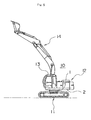
- a mobile hydraulic excavator 10 that travels at a work site to perform various work such as digging work and loading work of excavated earth or sand, an undercarriage 11 of the mobile hydraulic excavator 10, said undercarriage serving as a base for mounting thereon an upperstructure 12 and being capable of travelling by crawlers, theupperstructure 12 composed of a swing frame 2 and various devices arranged thereon and supported swingably relative to the undercarriage 11 via a swing circle 1, an operator's cab 13 in which an operator performs operations of a front 14 and the like, and the front 14 serving as a working section of the hydraulic excavator 10.
- a pinion drive device 5 Arranged on the swing frame 2 are a pinion drive device 5 to be described subsequently herein and a variety of devices or elements such as the operator' s cab 13, an engine compartment, a counterweight, and the like.
- the upperstructure 12 is a generic term for the assembly of these various devices or elements and the swing frame 2.
- the front 14 of the hydraulic excavator 10 is composed of a boom, an arm, a bucket and the like, and is arranged on a right front pat of the upperstructure 12 in a selectively raisable or lowerable fashion.
- the swing circle 1 and swing frame 2 will be described in detail subsequently herein.
- the swing frame 1 is composed by arranging an inner race 1a, an outer race 1b and rolling elements 1c, and supports the upperstructure 12 swingably relative to the undercarriage 11.
- the inner race 1a is provided on an inner circumferential portion thereof with an internal gear (ringgear) and is mounted on the side of the undercarriage 11.
- the outer race 1b is formed in an annular shape, and is rotatably arranged such that it concentrically surrounds the inner race 1a.
- the swing frame 2 is secured on the inner race 1a by bolts 8a.
- the rolling elements 1c are accommodated within an annular space between an outer circumferential wall of the inner race 1a and an inner circumferential wall of the outer race 1b, and have the function of a bearing.
- the swing frame 2 serves as a base for the upperstructure 12, and is swingably mounted on the undercarriage 11.
- a center frame 3 makes up a central part of the swing frame 2, and is swingably mounted on the undercarriage 11 via the swing circle 1.
- a bracket 3a is welded on the center frame 3, and is an annular bracket on which the pinion drive device 5 is secured by bolts 8b.
- the swing circle 1 is integrally united via the rolling elements 1c such that the swing circle 1 is prevented from falling apart.
- the inner race 1a is fastened by unillustrated bolts and nuts on the undercarriage 11 so that the swing circle 1 constructed as described above is fixed at a specified position on the undercarriage 11.
- the bolts 8a are inserted through the outer race 1b of the thus-fixed swing circle 1 and are then tightened to fix the center frame 3 at a specified position on the outer race 1b. Therefore, the outer race 1b is provided with many bolt insertion holes of a somewhat greater diameter than the bolts 8a (not illustrated) on a preset pitch circle.
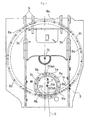
- the center frame 3 is provided with many bolt holes (their sign is omitted as they are holes located at the same locations as the bolts 8a), in which the bolts 8a are threaded, on a preset pitch circle R 1 as shown in FIG. 1.
- the swing frame 2 is composed of the center frame 3 and left and right side frames (not shown) on opposite sides of the center frame 3.
- a pair of vertical plates 3b are arranged upright such that they extend in a front-to-rear direction at a predetermined interval therebetween.
- the vertical plates 3b reinforce the center frame 3 to withstand forces applied from the front 14.
- a pinion insertion hole 3c is also formed to permit the insertion of the pinion 4, which serves to drive the swing circle and is to be described subsequently herein, such that the pinion is brought into meshing engagement with the internal gear of the ring 1a.
- the pinion insertion hole 3c is formed with a slightly larger diameter (as much as ⁇ ) than the circumferential portion of the pinion to permit smooth assembly work of the pinion 4.
- the bracket 3a for mounting the pinion drive device has been formed by bending a single bar-like plate into a circular form.
- the swing circle-driving pinion 4 is maintained in meshing engagement with the internal gear of the inner race 1a, and is rotationally driven by the pinion drive device 5.
- a knock pin 6 for positioning the pinion drive device serves to position the pinion drive device 5 relative to the center frame 3.
- the bolts 8a serve to threadedly fasten the center frame 3 on the outer race 1b
- the bolts 8b serve to threadedly fasten the pinion drive device 5 on the bracket 3a of the center frame 3
- the bracket 9 serves to secure the boom of the front 14 tiltably up and down.
- the pinion drive device 5 is provided with a hydraulic motor and a reduction gear box or the like arranged below the hydraulic motor to reduce its rotation, and is accommodated within a housing. A power output shaft of the reduction gear box is connected to the pinion 4.
- the pinion drive device 5 is fixed at a specified location on the center frame 3 by threadedly fastening it with the bolts 8b to the bracket 3a on the center frame 3 positioned and fixed on the outer race 1b.
- the flange portion 5a of the pinion drive device 5 is provided with many bolt insertion holes (not illustrated), which permit the insertion of the bolts 8b therethrough and are of a somewhat larger diameter than the bolt 8b, on a preset pitch circle.
- the bracket 3a for mounting the pinion drive device is provided with many bolt holes (their sign is omitted as they are holes located at the same locations as the bolts 8b), in which the bolts 8b are threaded, on a preset pitch circle R 2 as shown in FIG. 1.
- the teeth are underdimensioned beforehand to provide a predetermined amount of backlash (an inter-tooth play produced when the internal gear of the inner race 1a and the pinion 4 are brought into meshing engagement) at a place of meshing engagement between them for the purpose of preventing that the internal gear and the pinion 4 fit excessively tight with each other and the pinion 4 becomes no longer rotatable or for the purpose of absorbing dimensional errors of the internal gear and pinion 4 that unavoidably arise upon their fabrication.
- backlash an inter-tooth play produced when the internal gear of the inner race 1a and the pinion 4 are brought into meshing engagement
- the center frame 3 is fixed on the outer race 1b by inserting the bolts 8a through the bolt insertion holes, which are larger in diameter than the bolts 8a and are formed through the outer race 1b.
- the bolts 8a As there is a difference in diameter between these holes and the bolts 8a, a variation arises as much as the diametrical difference in the backlash at the place of meshing engagement between the internal gear of the inner race 1a and the pinion 4 depending on the state of mounting of the center frame 3.
- the flange portion 5a of the pinion drive device 5 is also provided with the bolt insertion holes of a somewhat greater diameter than the bolt 8b, so that there is a difference in diameter between these holes and the bolts 8b.
- a variation therefore, arises as much as the diametrical difference in the backlash at the place of meshing engagement between the internal gear and the pinion 4 depending on the state of mounting of the pinion drive device 5.
- the center-frame-positioning knock pin 6 and pinion-drive-device-positioning knock pin 7 are arranged to position the center frame 3 and pinion drive device 5 at locations as appropriate as possible relative to the outer race 1b and center frame 3, respectively, so that the pinion drive device 5 is positioned at a location as appropriate as possible relative to the swing circle 1 to reduce the variation in the backlash at the place of meshing engagement between the internal gear of the inner race 1a and the pinion 4.
- the internal gear of the inner race 1a and the pinion 4 are brought into meshing engagement on a center connection line S, which extend through a center O 1 of the swing circle 1 (the center of rotation of the outer race 1b) and a center O 2 of the pinion drive device 5 (the center of rotation of the pinion 4).
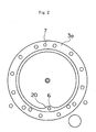
- a pin fit-in hole portion 20, through which the pin fit-in hole 3d is formed, is formed extending toward the pinion insertion hole 3c in the swing mechanism for the construction machine.
- the pin fit-in hole portion 20 is arranged locally on the center frame 3 at a location in the vicinity of the place of meshing engagement between the internal gear of the inner race 1a and the pinion 4, and the pin fit-in hole 3 is arranged through the extended portion.
- the center of the pin fit-in hole 3d is designed to be positioned on the center connection line S, which extends through the center O 1 rotation of the outer race 1b and the center O 2 of rotation of the pinion 4.
- the pin fit-in hole portion 20 is formed integrally with the center frame 3 upon forming the pinion insertion hole 3c.
- the knock pin 7 is arranged at one location on the pitch circle R 2 to position the pinion drive device 5 relative to the center frame 3.
- a pin fit-in hole (not illustrated) in which the knock pin 7 is fitted is arranged in the flange portion 5a of the pinion drive device 5, and further, a pin fit-in hole 3e is arranged in the pinion-drive-device-mounting bracket 3a such that the knock pin 7 is fitted in these pin fit-in hole to position the pinion drive device 5.
- This pin fit-in hole 3e is arranged such that its center is positioned on the center connection line S.
- the inner race 1a of the swing circle 1 is firstly fastened by bolts and nuts to a member on the side of the undercarriage 11 to fix the swing circle 1 at the specified location on the undercarriage 11 and also to fix the center-frame-positioning knock pin 6 on the outer race 1b of the swing circle 1.
- the center frame 3 is suspended and lowered such that the knock pin 6 is fitted in the pin fit-in hole 3d of the center frame 3 to position the center frame 3, the center frame 3 is secured on the outer race 1b by the bolts 8a.
- the pinion fit-in hole arranged in the flange portion 5a of the pinion drive device 5 is then brought into registration with the pin fit-in hole 3e of the pinion-drive-device-mounting bracket 3a. Thereafter, the knock pin 7 is fitted in the pin fit-in hole of the flange portion 5a and the pin fit-in hole 3e of the bracket 3a to position the pinion drive device 5, and the flange portion 5a of the pinion drive device 5 is secured on the center frame 3 by the bolts 8b.
- the pin fit-in hole portion 20 is arranged on the center frame 3 at the location in the vicinity of the place of meshing engagement between the internal gear of the inner race 1a and the pinion 4 such that the pin fit-in hole portion 20 extends toward the pinion insertion hole 3c, and the pin fit-in hole 3d is designed to be positioned on the center connection line S which extends through the center O 1 rotation of the outer race 3b and the center O 2 of rotation of the pinion 4. It is, therefore, possible to optimally arrange the center-frame-positioning knock pin 6. As a result, the backlash between the internal gear of the inner race 1a and the swing circle-driving pinion 4 can be reduced to a minimum need.
- the size of the pinion insertion hole 3c is not substantially reduced.
- the labor required for its insertion is, therefore, not substantially different from the conventional swing mechanism although it is necessary to insert the pinion 4 and its peripheral elements without any interference with the pin fit-in hole portion 20.
- the swing mechanism for the construction machine it is, therefore, possible not only to optimally arrange the center-frame-positioning knock pin 6 but also to perform the assembly of the pinion drive mechanism 5 smoothly as before.
- the swing mechanism for the construction machine enables the optimal arrangement of the center-frame-positioning knock pin 6 so that the backlash between the internal gear of the inner race 1a and the swing circle-driving pinion 4 can be reduced to a minimum need. It is, therefore, possible to improve the working accuracy of the construction machine and also to improve the comfort of use of the construction machine.
- the pin fit-in hole portion 20 is formed integrally with the center frame 3 especially upon formation of the pinion insertion hole 3c to arrange it on the center frame 3. Owing to the arrangement of the pin fit-in hole portion 20, the machining steps for the swing mechanism for the construction machine are not complicated.
- the backlash between the internal gear of the inner race 1a and the pinion 4 fluctuates to develop a variation depending on the machining accuracy and assembling accuracy of the swing mechanism of the construction machine. It is, therefore, desired to inspect with good accuracy whether or not the backlash after the assembly of the swing mechanism falls within a preset tolerance range.
- This backlash can be calculated based on the distance between the center O 1 of swinging of the swing circle 1 and the center O 2 of the pinion 4.
- the distance between the center O 1 of swinging and the center O 2 of rotation can be precisely calculated through conversion by measuring the distance between the knock pins 6 and 7 because the pinion-drive-device-positioning knock pin 7 is also arranged at one location like the center-frame-positioning knock pin 6 to have the centers of both the knock pins 6,7 positioned on the center connection line S which lies on a line that extends through the center O 1 of swinging and the center O 2 of rotation. It is, therefore, possible to efficiently inspect with good accuracy whether or not the backlash after the assembly of the swing mechanism falls within the tolerance range.
- the center of the pin fit-in hole 3e is positioned on the center connection line S.
- the pin fit-in hole 3e may, however, be arranged at a location adjacent to the center connection line S, and in essence, the desired objects can be achieved if the pin fit-in hole 3e is designed to be positioned in the vicinity of the center connection line S.
Landscapes
- Engineering & Computer Science (AREA)
- Mining & Mineral Resources (AREA)
- Civil Engineering (AREA)
- General Engineering & Computer Science (AREA)
- Structural Engineering (AREA)
- Gears, Cams (AREA)
- Jib Cranes (AREA)
- Component Parts Of Construction Machinery (AREA)
- Mounting Of Bearings Or Others (AREA)
Abstract
Description
- This invention relates to a swing mechanism for a construction machine such as a hydraulic excavator or crane, which is provided with a swing frame, an inner race having an internal gear and mounted on a side of a base such as an undercarriage, an outer race rotatably arranged surrounding the inner race and provided with the swing frame secured thereon by bolts, a pinion maintained in meshing engagement with the internal gear of the inner race, and a pinion drive device for rotationally driving the pinion, and also to a method for measuring its backlash.
- Construction machines such as hydraulic excavators include those constructed such that a swing frame and an upperstructure, which is arranged on the swing frame and is composed of various devices, can be caused to swing relative to a base such as an undercarriage. The term "swing mechanism for a construction machine" means a mechanism constructed by arranging a swing frame, an inner annular ring having an internal gear on an inner circumferential portion thereof and mounted on a side of a base, an outer annular ring rotatably arranged surrounding the inner race and provided with the swing frame secured thereon by bolts, a pinion maintained in meshing engagement with the internal gear of the inner race, and a pinion drive device for rotationally driving the pinion such that such an upperstructure is allowed to achieve a swing motion. This pinion drive device serves as a drive source for causing the upperstructure to swing relative to the base, and in general, is equipped with a motor such as a hydraulic motor and a reduction gear box for transmitting rotation of the motor at a reduced speed to a pinion and is arranged on the side of the swing frame.
- A swing mechanism for a construction machine is designed such that a pinion on the side of a swing frame is brought into meshing engagement with an internal gear of an inner race on the side of an undercarriage to permit swinging of the swing frame, which forms an upperstructure, relative to a base. It is, therefore, necessary to maintain the pinion and the inner gear in adequate meshing engagement so that the upperstructure does not shake upon swinging. When plural hydraulic excavators are assembled, however, a backlash formed at a place of meshing engagement between a rotating pinion and a ring gear on an inner race of a swing circle in each swing mechanism substantially varies from one swing mechanism to another, resulting in a problem that the hydraulic excavators tend to be reduced in quality.
- To cope with such a problem, an invention disclosed, for example, in Patent Publication 1 has been proposed. Inamounting structure for a swing unit that the mounting structure is arranged on a construction machine equipped with a traveling unit and the swing unit arranged on the traveling unit via a swing circle having an inner race and outer race, the swing unit having a rotational pinion is secured by bolts on a main frame of the swing unit, the outer race of the swing circle is secured by bolts on the main frame of the swing unit, the inner race of the swing circle is secured by bolts on the traveling unit, and the swing unit is arranged to maintain the inner race of the swing circle in meshing engagement with a ring gear of the inner race of the swing circle, the invention is characterized in that at least one of a single pin for the swing unit, said single pin connecting the swing unit to the main frame, and a single pin for the swing circle, said pin connecting the outer race of the swing circle to the main frame, is arranged and at least one of a pin for the swing unit and a pin for the swing circle is arranged on a center connecting line, which connects a center of the above-described swing circle and a center of the swing unit with each other, or in the vicinity of the center connecting line.
- Patent Publication 1: JP-A-2000-336696 (pages 3-5, Figs. 1-2).
- The existence of a backlash between an inner gear of an inner race and a pinion causes a front on a swing frame to shake, and hence, leads to a reduction in the working accuracy. When a swing frame, for example, in a hydraulic shovel rattles during digging operation by a bucket, vibrations are transmitted to the bucket via a boom and arm. To the bucket located far apart from the center of its swinging motion, the vibrations are transmitted in a magnified state, thereby causing the bucket to shake to unexpected large extent and reducing the accuracy of the digging work. It is, therefore, desired to fix a center frame and a pinion drive device at appropriate locations such that the backlash between the inner gear and the pinion is minimized as much as possible. Especially in recent years, it is demanded to reduce such a backlash to a minimum need such that a construction machine is improved in the working accuracy or in the comfort of use.
- In this respect, a description will be made about a conventional swing mechanism for a construction. A pinion drive device is designed to be positioned on a center frame at two locations by two
knock pins 7, the pinion drive device can be always fixed at an appropriate location. Thecenter frame 3 is in turn designed to be positioned on an outer race by only oneknock pin 6. Whenever thecenter frame 3 is positioned, thecenter frame 3 is displaced by a difference in diameter between bolt insertion holes of the outer race 1b andbolts 8a such that thecenter frame 3 rocks about theknock pin 6. Thisknock pin 6 is secured at a location substantially far from a center connection line S. When thecenter frame 3 rocks about theknock pin 6, a center O1 of a swing circle 1 may, therefore, be shifted to an unnegligible extent from the optimal location in a direction of arrow Y along the center connection line S. - To resolve such a problem, it is only necessary to secure the center-frame-
positioning knock pin 6 around the center connection line S. This positioning, however, involves a difficulty from the practical viewpoint, because in relation to the modules, tooth numbers and the like of the internal gear and apinion 4, a bracket for mounting the pinion drive device is generally arranged astride the outer race so that the center frame does not have any sufficient space for the arrangement of the knock pin. If the diameter of the pinion insertion hole is reduced to increase this space, a great deal of labor is required to insert the pinion and its peripheral elements into the pinion insertion hole without any interference with the circumferential edge portion of the hole upon assembling the pinion drive device, thereby making it impossible to smoothly perform the assembly of the pinion drive device. - When an attempt is made to reduce a backlash, it is impossible to determine how much the backlash has been reduced unless the amount of the backlash is known. Accordingly, there is also a desire for the development of a technique that makes it possible to determine the amount of a backlash and then, to determine whether or not it is an appropriate amount.
- The present invention has been completed to resolve such problems, and has as an obj ect the provision of a swing mechanism for a construction machine, which can smoothly perform the assembly of a pinion drive device while enabling optimal arrangement of a swing frame-positioning knock pin.
- Another object of the present invention is to provide a method for measuring a backlash in a swing mechanism for a construction machine, which can surely determine the amount of a backlash and also to determine whether or not the amount of the backlash is adequate.
- To achieve the above-described objects, the present invention is characterized in that in a swing mechanism for a construction machine, said swing mechanism being provided with a swing frame, an inner race having an internal gear on an inner circumferential portion thereof and mounted on a side of a base, an outer race rotatably arranged surrounding the inner race and provided with the swing frame mounted thereon, a pinion inserted through a pinion insertion hole formed in the swing frame and maintained in meshing engagement with the internal gear, a pinion drive device for rotationally driving the pinion, and a pin fit-in hole arranged in the swing frame such that a knock pin fixed on the outer race is fitted in the pin fit-in hole to position the swing frame, a pin fit-in hole portion through which the pin fit-in hole is formed is arranged on the swing frame at a location in a vicinity of a place of meshing engagement between the pinion and the internal gear such that the pin fit-in hole portion extends toward the pinion insertion hole, and the pin fit-in hole is located on or in a vicinity of a line that extends through a center of rotation of the outer race and a center of rotation of the pinion.
- In the above-described swing mechanism, it is preferred to arrange the knock pin for positioning the pinion drive device between the swing frame and the pinion drive device and to locate a center of the knock pin for positioning each of the swing frame, said knock pin being fitted in the pin fit-in hole, and a center of a knock pin for positioning the pinion drive on or in a vicinity of a line that extends through the center of rotation of the outer race and the center of rotation of the pinion. The pin fit-in hole can be arranged in a center frame of the swing frame, and the fit-in hole in which the knock pin for positioning the pinion drive device is fitted can be arranged through a flange portion of the pinion drive device and a bracket for mounting the pinion drive device.
- A second aspect is characterized in that in a method for measuring a backlash of a swing mechanism for a construction machine, said swing mechanism being provided with a swing frame, an inner race having an internal gear on an inner circumferential portion thereof and mounted on a side of a base, an outer race rotatably arranged surrounding the inner race and provided with the swing frame mounted thereon, a pinion inserted through a pinion insertion hole formed in the swing frame and maintained in meshing engagement with the internal gear, a pinion drive device for rotationally driving the pinion, and a pin fit-in hole arranged in the swing frame such that a knock pin fixed on the outer race is fitted in the pin fit-in hole to position the swing frame, a distance between a center of the knock pin for positioning the swing frame, said knock pin being fitted in the pin fit-in hole, and a center of a knock pin arranged between the swing frame and the pinion drive device to position the pinion drive device is measured, a distance between a center of rotation of the outer race and a center of rotation of the pinion is calculated from the distance so measured, and the backlash to be formed after assembly of the swing mechanism is determined from the distance so calculated.
- In the above-describedmethod, it is possible to determine, from the backlash so determined, whether or not the backlash after the assembly of the swingmechanism falls within a tolerance range.
- The swing mechanism according to the present invention for the construction machine has made it possible to optimally arrange the swing frame-positioning knock pin, because a pin fit-in hole portion is arranged on the swing frame at a location in the vicinity of the place of meshing engagement between the pinion and the internal gear such that the pin fit-in hole portion extends toward the pinion insertion hole and the pin fit-in hole is located around the line that extends through the center of rotation of the outer race and the center of rotation of the pinion. As a result, the backlash between the internal gear of the inner race and the swing circle-driving pinion can be reduced to a minimum need.
- Nonetheless, the pinion insertion hole is not substantially reduced because the pin fit-in hole portion is arranged only locally although it extends toward the pinion insertion hole. Owing to this feature, the labor required for the insertion of the pinion and its peripheral elements upon assembling the pinion drive device is not practically different from the past although it is necessary to insert them without any interference with the pin fit-in hole portion. With the swing mechanism according to the present invention for the construction machine, it is possible not only to make feasible the optimal arrangement of the swing frame-positioning knock frame but also to smoothly conduct the assembly of the pinion drive device as before.
- Moreover, the distance between the center of swinging and that of rotation can be precisely calculated through conversion by measuring the distance between both the knock pins. As a result, it is possible to efficiently inspect with good accuracy whether or not the backlash after the assembly of the swing mechanism falls within a tolerance range.
- As has been described above, the swing mechanism according to the present invention for the construction machine makes it possible smoothly perform the assembly of the pinion drive device while permitting the optimal arrangement of the swing frame-positioning knock pin. In addition, the swing mechanism according to the present invention for the construction machine can achieve the optimal arrangement of the swing frame-positioning knock pin so that the backlash between the internal gear of the inner race and the swing circle-driving pinion can be reduced to a minimum need. This makes it possible to improve the working accuracy of the construction machine and also to improve the comfort of use of the construction machine. Furthermore, it is also possible to efficiently determine with good accuracy whether or not the backlash after the assembly of the swing mechanism falls within a tolerance range.
-
- FIG. 1 is a fragmentary plan view of a swing mechanism according an embodiment of the present invention for a construction machine.
- FIG. 2 is a plan view showing on an enlarged scale a bracket for mounting a pinion drive device and its adjacent elements in FIG. 1.
- FIG. 3 is a fragmentary perspective view of a swing mechanism according the embodiment of the present invention for the construction machine.
- FIG. 4 is a side view of the pinion drive device and its peripheral elements of FIG. 3 in the swing mechanism for the construction machine, and illustrates a swing circle and its adjacent elements in cross-section.
- FIG. 5 is a side view of a hydraulic excavator as one example of the construction machine.
- With reference to the drawings, a description will hereinafter be made about a best mode for carrying out the present invention.
- Firstly, the overall construction of the hydraulic excavator mentioned as an illustrative construction machine will be outlined based on FIG. 5.
- Depicted are a mobile
hydraulic excavator 10 that travels at a work site to perform various work such as digging work and loading work of excavated earth or sand, an undercarriage 11 of the mobilehydraulic excavator 10, said undercarriage serving as a base for mounting thereon anupperstructure 12 and being capable of travelling by crawlers,theupperstructure 12 composed of aswing frame 2 and various devices arranged thereon and supported swingably relative to the undercarriage 11 via a swing circle 1, an operator'scab 13 in which an operator performs operations of afront 14 and the like, and thefront 14 serving as a working section of thehydraulic excavator 10. - Arranged on the
swing frame 2 are apinion drive device 5 to be described subsequently herein and a variety of devices or elements such as the operator' scab 13, an engine compartment, a counterweight, and the like. Theupperstructure 12 is a generic term for the assembly of these various devices or elements and theswing frame 2. Thefront 14 of thehydraulic excavator 10 is composed of a boom, an arm, a bucket and the like, and is arranged on a right front pat of theupperstructure 12 in a selectively raisable or lowerable fashion. The swing circle 1 andswing frame 2 will be described in detail subsequently herein. - Referring to FIGS. 1 through 5, a description will next be made about the details of the swing mechanism for the construction machine and a method of its assembly.
- In these drawings, the swing frame 1 is composed by arranging an inner race 1a, an outer race 1b and rolling elements 1c, and supports the
upperstructure 12 swingably relative to the undercarriage 11. The inner race 1a is provided on an inner circumferential portion thereof with an internal gear (ringgear) and is mounted on the side of the undercarriage 11. The outer race 1b is formed in an annular shape, and is rotatably arranged such that it concentrically surrounds the inner race 1a. Theswing frame 2 is secured on the inner race 1a bybolts 8a. The rolling elements 1c are accommodated within an annular space between an outer circumferential wall of the inner race 1a and an inner circumferential wall of the outer race 1b, and have the function of a bearing. Theswing frame 2 serves as a base for theupperstructure 12, and is swingably mounted on the undercarriage 11. Acenter frame 3 makes up a central part of theswing frame 2, and is swingably mounted on the undercarriage 11 via the swing circle 1. Abracket 3a is welded on thecenter frame 3, and is an annular bracket on which thepinion drive device 5 is secured bybolts 8b. - By accommodating the rolling elements 1c within the annular space between the inner race 1a and the outer race 1b, the swing circle 1 is integrally united via the rolling elements 1c such that the swing circle 1 is prevented from falling apart. As illustrated in FIG. 4, the inner race 1a is fastened by unillustrated bolts and nuts on the undercarriage 11 so that the swing circle 1 constructed as described above is fixed at a specified position on the undercarriage 11. The
bolts 8a are inserted through the outer race 1b of the thus-fixed swing circle 1 and are then tightened to fix thecenter frame 3 at a specified position on the outer race 1b. Therefore, the outer race 1b is provided with many bolt insertion holes of a somewhat greater diameter than thebolts 8a (not illustrated) on a preset pitch circle. Corresponding to these holes, thecenter frame 3 is provided with many bolt holes (their sign is omitted as they are holes located at the same locations as thebolts 8a), in which thebolts 8a are threaded, on a preset pitch circle R1 as shown in FIG. 1. - In the illustrated embodiment, the
swing frame 2 is composed of thecenter frame 3 and left and right side frames (not shown) on opposite sides of thecenter frame 3. On thecenter frame 3, a pair ofvertical plates 3b are arranged upright such that they extend in a front-to-rear direction at a predetermined interval therebetween. Thevertical plates 3b reinforce thecenter frame 3 to withstand forces applied from the front 14. In thecenter frame 3, apinion insertion hole 3c is also formed to permit the insertion of thepinion 4, which serves to drive the swing circle and is to be described subsequently herein, such that the pinion is brought into meshing engagement with the internal gear of the ring 1a. As depicted in FIG. 4, thepinion insertion hole 3c is formed with a slightly larger diameter (as much as δ) than the circumferential portion of the pinion to permit smooth assembly work of thepinion 4. Thebracket 3a for mounting the pinion drive device has been formed by bending a single bar-like plate into a circular form. - The swing circle-driving
pinion 4 is maintained in meshing engagement with the internal gear of the inner race 1a, and is rotationally driven by thepinion drive device 5. Aknock pin 6 for positioning the pinion drive device serves to position thepinion drive device 5 relative to thecenter frame 3. Thebolts 8a serve to threadedly fasten thecenter frame 3 on the outer race 1b, thebolts 8b serve to threadedly fasten thepinion drive device 5 on thebracket 3a of thecenter frame 3, and the bracket 9 serves to secure the boom of the front 14 tiltably up and down. - The
pinion drive device 5 is provided with a hydraulic motor and a reduction gear box or the like arranged below the hydraulic motor to reduce its rotation, and is accommodated within a housing. A power output shaft of the reduction gear box is connected to thepinion 4. Thepinion drive device 5 is fixed at a specified location on thecenter frame 3 by threadedly fastening it with thebolts 8b to thebracket 3a on thecenter frame 3 positioned and fixed on the outer race 1b. For this purpose, theflange portion 5a of thepinion drive device 5 is provided with many bolt insertion holes (not illustrated), which permit the insertion of thebolts 8b therethrough and are of a somewhat larger diameter than thebolt 8b, on a preset pitch circle. Corresponding to these holes, thebracket 3a for mounting the pinion drive device is provided with many bolt holes (their sign is omitted as they are holes located at the same locations as thebolts 8b), in which thebolts 8b are threaded, on a preset pitch circle R2 as shown in FIG. 1. - It is to be noted that upon designing the internal gear of the inner race 1a and the teeth of the
pinion 4, the teeth are underdimensioned beforehand to provide a predetermined amount of backlash (an inter-tooth play produced when the internal gear of the inner race 1a and thepinion 4 are brought into meshing engagement) at a place of meshing engagement between them for the purpose of preventing that the internal gear and thepinion 4 fit excessively tight with each other and thepinion 4 becomes no longer rotatable or for the purpose of absorbing dimensional errors of the internal gear andpinion 4 that unavoidably arise upon their fabrication. Unless the swing circle 1 andpinion 4 are accurately positioned and fixed at appropriate locations upon assembling them, an unnecessarily large backlash is produced so that theupperstructure 12 shakes upon swinging. - On the other hand, the
center frame 3 is fixed on the outer race 1b by inserting thebolts 8a through the bolt insertion holes, which are larger in diameter than thebolts 8a and are formed through the outer race 1b. As there is a difference in diameter between these holes and thebolts 8a, a variation arises as much as the diametrical difference in the backlash at the place of meshing engagement between the internal gear of the inner race 1a and thepinion 4 depending on the state of mounting of thecenter frame 3. Further, theflange portion 5a of thepinion drive device 5, saidflange portion 5a being fixed on thecenter frame 3 by thebolts 8a, is also provided with the bolt insertion holes of a somewhat greater diameter than thebolt 8b, so that there is a difference in diameter between these holes and thebolts 8b. A variation, therefore, arises as much as the diametrical difference in the backlash at the place of meshing engagement between the internal gear and thepinion 4 depending on the state of mounting of thepinion drive device 5. - The center-frame-
positioning knock pin 6 and pinion-drive-device-positioning knock pin 7 are arranged to position thecenter frame 3 andpinion drive device 5 at locations as appropriate as possible relative to the outer race 1b andcenter frame 3, respectively, so that thepinion drive device 5 is positioned at a location as appropriate as possible relative to the swing circle 1 to reduce the variation in the backlash at the place of meshing engagement between the internal gear of the inner race 1a and thepinion 4. The internal gear of the inner race 1a and thepinion 4 are brought into meshing engagement on a center connection line S, which extend through a center O1 of the swing circle 1 (the center of rotation of the outer race 1b) and a center O2 of the pinion drive device 5 (the center of rotation of the pinion 4). To make the backlash at the place of meshing engagement between both the gears closer to an optimal value set from the designing standpoint, it is necessary to prevent the positions of the centers O1,O2 from the optimal positions in a direction of arrow Y along the center connection line S. - For the purpose of providing a pin fit-in
hole 3d with thecenter frame 3 to position thecenter frame 3 by fitting the center-frame-positioning knock pin 6, a pin fit-inhole portion 20, through which the pin fit-inhole 3d is formed, is formed extending toward thepinion insertion hole 3c in the swing mechanism for the construction machine. The pin fit-inhole portion 20 is arranged locally on thecenter frame 3 at a location in the vicinity of the place of meshing engagement between the internal gear of the inner race 1a and thepinion 4, and the pin fit-inhole 3 is arranged through the extended portion. In the illustrated embodiment, the center of the pin fit-inhole 3d is designed to be positioned on the center connection line S, which extends through the center O1 rotation of the outer race 1b and the center O2 of rotation of thepinion 4. To arrange the pin fit-inhole portion 20 on thecenter frame 3, the pin fit-inhole portion 20 is formed integrally with thecenter frame 3 upon forming thepinion insertion hole 3c. - On the other hand, the
knock pin 7 is arranged at one location on the pitch circle R2 to position thepinion drive device 5 relative to thecenter frame 3. For this purpose, a pin fit-in hole (not illustrated) in which theknock pin 7 is fitted is arranged in theflange portion 5a of thepinion drive device 5, and further, a pin fit-inhole 3e is arranged in the pinion-drive-device-mountingbracket 3a such that theknock pin 7 is fitted in these pin fit-in hole to position thepinion drive device 5. This pin fit-inhole 3e is arranged such that its center is positioned on the center connection line S. - Upon assembling the above-described swing mechanism for the construction machine, the inner race 1a of the swing circle 1 is firstly fastened by bolts and nuts to a member on the side of the undercarriage 11 to fix the swing circle 1 at the specified location on the undercarriage 11 and also to fix the center-frame-
positioning knock pin 6 on the outer race 1b of the swing circle 1. After thecenter frame 3 is suspended and lowered such that theknock pin 6 is fitted in the pin fit-inhole 3d of thecenter frame 3 to position thecenter frame 3, thecenter frame 3 is secured on the outer race 1b by thebolts 8a. The pinion fit-in hole arranged in theflange portion 5a of thepinion drive device 5 is then brought into registration with the pin fit-inhole 3e of the pinion-drive-device-mountingbracket 3a. Thereafter, theknock pin 7 is fitted in the pin fit-in hole of theflange portion 5a and the pin fit-inhole 3e of thebracket 3a to position thepinion drive device 5, and theflange portion 5a of thepinion drive device 5 is secured on thecenter frame 3 by thebolts 8b. - In the swing mechanism for the construction machine, the pin fit-in
hole portion 20 is arranged on thecenter frame 3 at the location in the vicinity of the place of meshing engagement between the internal gear of the inner race 1a and thepinion 4 such that the pin fit-inhole portion 20 extends toward thepinion insertion hole 3c, and the pin fit-inhole 3d is designed to be positioned on the center connection line S which extends through the center O1 rotation of theouter race 3b and the center O2 of rotation of thepinion 4. It is, therefore, possible to optimally arrange the center-frame-positioning knock pin 6. As a result, the backlash between the internal gear of the inner race 1a and the swing circle-drivingpinion 4 can be reduced to a minimum need. - As the pin fit-in
hole portion 20 is arranged only locally although it extends toward thepinion insertion hole 3c, the size of thepinion insertion hole 3c is not substantially reduced. Upon assembling thepinion drive device 5, the labor required for its insertion is, therefore, not substantially different from the conventional swing mechanism although it is necessary to insert thepinion 4 and its peripheral elements without any interference with the pin fit-inhole portion 20. With the swing mechanism for the construction machine, it is, therefore, possible not only to optimally arrange the center-frame-positioning knock pin 6 but also to perform the assembly of thepinion drive mechanism 5 smoothly as before. - The swing mechanism for the construction machine enables the optimal arrangement of the center-frame-
positioning knock pin 6 so that the backlash between the internal gear of the inner race 1a and the swing circle-drivingpinion 4 can be reduced to a minimum need. It is, therefore, possible to improve the working accuracy of the construction machine and also to improve the comfort of use of the construction machine. In the illustrated embodiment, for the purpose of arranging the pin fit-inhole portion 20 on thecenter frame 3, the pin fit-inhole portion 20 is formed integrally with thecenter frame 3 especially upon formation of thepinion insertion hole 3c to arrange it on thecenter frame 3. Owing to the arrangement of the pin fit-inhole portion 20, the machining steps for the swing mechanism for the construction machine are not complicated. - The backlash between the internal gear of the inner race 1a and the
pinion 4 fluctuates to develop a variation depending on the machining accuracy and assembling accuracy of the swing mechanism of the construction machine. It is, therefore, desired to inspect with good accuracy whether or not the backlash after the assembly of the swing mechanism falls within a preset tolerance range. This backlash can be calculated based on the distance between the center O1 of swinging of the swing circle 1 and the center O2 of thepinion 4. However, it has heretofore been difficult to measure with good accuracy the backlash after the assembly of the swing mechanism because the actual locations of the center O1 of swinging and the center O2 of rotation cannot be determined. In the illustrated embodiment, however, the distance between the center O1 of swinging and the center O2 of rotation can be precisely calculated through conversion by measuring the distance between the knock pins 6 and 7 because the pinion-drive-device-positioning knock pin 7 is also arranged at one location like the center-frame-positioning knock pin 6 to have the centers of both the knock pins 6,7 positioned on the center connection line S which lies on a line that extends through the center O1 of swinging and the center O2 of rotation. It is, therefore, possible to efficiently inspect with good accuracy whether or not the backlash after the assembly of the swing mechanism falls within the tolerance range. - In the illustrated embodiment, it is designed especially that the center of the pin fit-in
hole 3e is positioned on the center connection line S. The pin fit-inhole 3e may, however, be arranged at a location adjacent to the center connection line S, and in essence, the desired objects can be achieved if the pin fit-inhole 3e is designed to be positioned in the vicinity of the center connection line S.
Claims (6)
- A swing mechanism for a construction machine, said swing mechanism being provided with:a swing frame,an inner race having an internal gear on an inner circumferential portion thereof and mounted on a side of a base,an outer race rotatably arranged surrounding said inner race and provided with said swing frame mounted thereon,a pinion inserted through a pinion insertion hole formed in said swing frame and maintained in meshing engagement with said internal gear,a pinion drive device for rotationally driving said pinion, anda pin fit-in hole arranged in said swing frame such that a knock pin fixed on said outer race is fitted in said pin fit-in hole to position said swing frame, characterized in that:a pin fit-in hole portion through which said pin fit-in hole is formed is arranged on said swing frame at a location in a vicinity of a place of meshing engagement between said pinion and said internal gear such that said pin fit-in hole portion extends toward said pinion insertion hole, and said pin fit-in hole is located on or in a vicinity of a line that extends through a center of rotation of said outer race and a center of rotation of said pinion.
- A swing mechanism according to claim 1, wherein:said knock pin for positioning said pinion drive device is arrangedbetween said swing frame and saidpinion drive device, anda center of said knockpin for positioning said swing frame, said knock pin being fitted in said pin fit-in hole, and a center of a knock pin for positioning said pinion drive device are each located on or in a vicinity of a line that extends through said center of rotation of said outer race and said center of rotation of said pinion.
- A swing mechanism according to claim 2, wherein :said pin fit-in hole is arranged in a center frame of said swing frame.
- A swing mechanism according to claim 2, wherein said fit-in hole in which said knock pin for positioning said pinion drive device is fitted is arranged through a flange portion of said pinion drive device and a bracket for mounting said pinion drive device.
- A method for measuring a backlash of a swing mechanism for a construction machine, said swing mechanism being provided with a swing frame, an inner race having an internal gear on an inner circumferential portion thereof and mounted on a side of a base, an outer race rotatably arranged surrounding said inner race and provided with said swing frame mounted thereon, a pinion inserted through a pinion insertion hole formed in said swing frame and maintained in meshing engagement with said internal gear, a pinion drive device for rotationally driving said pinion, and a pin fit-in hole arranged in said swing frame such that a knock pin fixed on said outer race is fitted in said pin fit-in hole to position said swing frame, which comprises:measuring a distance between a center of said knock pin for positioning said swing frame, said knock pin being fitted in said pin fit-in hole, and a center of a knock pin arranged between said swing frame and said pinion drive device to position said pinion drive device,calculating, from the distance so measured, a distance between a center of rotation of said outer race and a center of rotation of said pinion, anddetermining, from the distance so calculated, said backlash to be formed after assembly of said swing mechanism.
- A method according to claim 5, further comprising determining, from the backlash so determined, whether or not the backlash after the assembly of said swing mechanism falls within a tolerance range.
Applications Claiming Priority (2)
| Application Number | Priority Date | Filing Date | Title |
|---|---|---|---|
| JP2003101799A JP3981339B2 (en) | 2003-04-04 | 2003-04-04 | Construction machinery swivel mechanism |
| PCT/JP2004/004888 WO2004090242A1 (en) | 2003-04-04 | 2004-04-05 | Rotation mechanism for construction machine and method of measuring backlash in the mechanism |
Publications (3)
| Publication Number | Publication Date |
|---|---|
| EP1630302A1 true EP1630302A1 (en) | 2006-03-01 |
| EP1630302A4 EP1630302A4 (en) | 2011-04-13 |
| EP1630302B1 EP1630302B1 (en) | 2016-12-14 |
Family
ID=33156779
Family Applications (1)
| Application Number | Title | Priority Date | Filing Date |
|---|---|---|---|
| EP04725795.1A Expired - Lifetime EP1630302B1 (en) | 2003-04-04 | 2004-04-05 | Rotation mechanism for construction machine and method of measuring backlash in the mechanism |
Country Status (6)
| Country | Link |
|---|---|
| US (1) | US7832301B2 (en) |
| EP (1) | EP1630302B1 (en) |
| JP (1) | JP3981339B2 (en) |
| KR (1) | KR101075054B1 (en) |
| CN (1) | CN100577929C (en) |
| WO (1) | WO2004090242A1 (en) |
Cited By (1)
| Publication number | Priority date | Publication date | Assignee | Title |
|---|---|---|---|---|
| CN112555388A (en) * | 2020-12-03 | 2021-03-26 | 伯朗特机器人股份有限公司 | Apparatus for determining optimal gear center distance and method thereof |
Families Citing this family (9)
| Publication number | Priority date | Publication date | Assignee | Title |
|---|---|---|---|---|
| KR100979704B1 (en) * | 2008-07-21 | 2010-09-02 | 하나로테크 주식회사 | Swinging Plate Structure for Construction Heavy Equipment |
| CN101811644B (en) * | 2009-02-25 | 2014-05-14 | 马尼托瓦克起重机有限公司 | Swing drive system for cranes |
| JP5015988B2 (en) * | 2009-03-25 | 2012-09-05 | 日立建機株式会社 | Swivel construction machine |
| JP5547662B2 (en) * | 2011-01-14 | 2014-07-16 | 日立建機株式会社 | Construction machinery |
| DE102011078080A1 (en) * | 2011-06-27 | 2012-12-27 | Schaeffler Technologies AG & Co. KG | rotary joint |
| US10161504B2 (en) * | 2016-10-28 | 2018-12-25 | Deere & Company | Backlash adjustment system and method |
| CN106516979B (en) * | 2016-12-05 | 2017-12-15 | 上海振华重工(集团)股份有限公司 | A kind of row of slew gear fills method |
| CN108643273B (en) * | 2018-07-09 | 2023-11-28 | 三一重机有限公司 | Positioning pin, counterweight positioning structure and assembly method, excavator |
| EP3786491A1 (en) * | 2019-08-27 | 2021-03-03 | Güdel Group AG c/o Güdel AG | Process for the adjustment of backlash between a pinon and a rack in a rack-pinion drive |
Family Cites Families (13)
| Publication number | Priority date | Publication date | Assignee | Title |
|---|---|---|---|---|
| US3972378A (en) * | 1975-01-23 | 1976-08-03 | Caterpillar Tractor Co. | Swing lock means for an hydraulic excavator |
| DE3522600A1 (en) * | 1985-06-25 | 1987-01-08 | Bayerische Motoren Werke Ag | Method for setting the backlash of the bevel gear set of a final drive unit |
| JPH057322Y2 (en) * | 1987-04-17 | 1993-02-24 | ||
| FR2633602B3 (en) * | 1988-06-29 | 1991-05-31 | Roux Ind Sa | TELESCOPIC CRANE DEVICE, PARTICULARLY FOR LIFTING AND PLACING TELEGRAPHIC OR THE LIKE POSTS |
| US5176267A (en) * | 1990-07-23 | 1993-01-05 | The Manitowoc Company, Inc. | Quick disconnect system for construction equipment with rotatable upper works |
| JP2551895Y2 (en) * | 1993-10-14 | 1997-10-27 | 住友建機株式会社 | Mounting structure of upper revolving superstructure for construction machinery |
| JP3078747B2 (en) * | 1996-03-29 | 2000-08-21 | 新キャタピラー三菱株式会社 | Gear backlash adjustment method and adjustment structure for construction machinery |
| KR100298021B1 (en) * | 1996-10-08 | 2002-04-06 | 세구치 류이치 | Manufacturing method of swash plate hydraulic rotor and casing for two rotor |
| US6035736A (en) * | 1997-11-07 | 2000-03-14 | Caterpillar Inc. | Adjustable pinion gear mounting arrangement |
| JP3430203B2 (en) | 1999-05-25 | 2003-07-28 | 日立建機株式会社 | Revolving structure mounting structure |
| CN2417205Y (en) * | 2000-04-25 | 2001-01-31 | 张玉生 | Hydraulic rotating means |
| JP3565775B2 (en) * | 2000-09-27 | 2004-09-15 | 株式会社小松製作所 | Swivel for construction machinery |
| JP4424844B2 (en) * | 2000-12-13 | 2010-03-03 | 株式会社小松製作所 | Work machine swivel reducer |
-
2003
- 2003-04-04 JP JP2003101799A patent/JP3981339B2/en not_active Expired - Fee Related
-
2004
- 2004-04-05 WO PCT/JP2004/004888 patent/WO2004090242A1/en not_active Ceased
- 2004-04-05 EP EP04725795.1A patent/EP1630302B1/en not_active Expired - Lifetime
- 2004-04-05 CN CN200480008755A patent/CN100577929C/en not_active Expired - Fee Related
- 2004-04-05 KR KR1020057018078A patent/KR101075054B1/en not_active Expired - Fee Related
- 2004-04-05 US US10/551,839 patent/US7832301B2/en not_active Expired - Lifetime
Cited By (1)
| Publication number | Priority date | Publication date | Assignee | Title |
|---|---|---|---|---|
| CN112555388A (en) * | 2020-12-03 | 2021-03-26 | 伯朗特机器人股份有限公司 | Apparatus for determining optimal gear center distance and method thereof |
Also Published As
| Publication number | Publication date |
|---|---|
| KR20050115934A (en) | 2005-12-08 |
| US20070034033A1 (en) | 2007-02-15 |
| EP1630302B1 (en) | 2016-12-14 |
| EP1630302A4 (en) | 2011-04-13 |
| KR101075054B1 (en) | 2011-10-21 |
| JP2004346484A (en) | 2004-12-09 |
| JP3981339B2 (en) | 2007-09-26 |
| WO2004090242A1 (en) | 2004-10-21 |
| CN100577929C (en) | 2010-01-06 |
| CN1768184A (en) | 2006-05-03 |
| US7832301B2 (en) | 2010-11-16 |
Similar Documents
| Publication | Publication Date | Title |
|---|---|---|
| EP1630302B1 (en) | Rotation mechanism for construction machine and method of measuring backlash in the mechanism | |
| EP2700752A1 (en) | Boom for construction machine | |
| JP5181017B2 (en) | Work vehicle | |
| JP5349182B2 (en) | Swivel drive device for construction machinery | |
| CN101784434B (en) | Final reduction gear, construction machine equipped with the same, and method of winding crawler belt | |
| EP1479832B1 (en) | Crawler frame for a construction machine | |
| EP1479833B1 (en) | Crawler frame for a construction machine | |
| KR20220038018A (en) | Construction Machinery, Antenna Mounting Method, and Antenna Mounting Structure | |
| JP2002180500A (en) | Work machine turning reducer | |
| JP2003268803A (en) | Swivel for construction machinery | |
| JP3695301B2 (en) | Small swing excavator at the rear end | |
| US7857083B2 (en) | Excavation machine | |
| JP2021031856A (en) | Multi shaft drilling machine | |
| JP7624326B2 (en) | Construction Machinery | |
| JP2000345586A (en) | Swivel for construction machinery | |
| JP5015988B2 (en) | Swivel construction machine | |
| JP2000204592A (en) | Construction equipment step mounting structure | |
| JP5152267B2 (en) | Boom rotary work machine | |
| JP2009203683A (en) | Working vehicle | |
| JP4477484B2 (en) | Undercover mounting structure for construction machinery | |
| JP4972531B2 (en) | Travel reducer and construction machinery | |
| JP5415385B2 (en) | Swivel construction machine | |
| JP4236609B2 (en) | Mounting structure of rotary joint on turning work machine | |
| JP4364605B2 (en) | Truck frame manufacturing method for construction machinery | |
| JP4999591B2 (en) | Piping arrangement structure in the truck frame |
Legal Events
| Date | Code | Title | Description |
|---|---|---|---|
| PUAI | Public reference made under article 153(3) epc to a published international application that has entered the european phase |
Free format text: ORIGINAL CODE: 0009012 |
|
| 17P | Request for examination filed |
Effective date: 20051103 |
|
| AK | Designated contracting states |
Kind code of ref document: A1 Designated state(s): AT BE BG CH CY CZ DE DK EE ES FI FR GB GR HU IE IT LI LU MC NL PL PT RO SE SI SK TR |
|
| DAX | Request for extension of the european patent (deleted) | ||
| RIN1 | Information on inventor provided before grant (corrected) |
Inventor name: NOZUE, AKIYASU Inventor name: ISOBE, HIROYUKI;C/O HITACHI CON. MACHINERY CO.LTD Inventor name: TANAKA, NOZOMU |
|
| A4 | Supplementary search report drawn up and despatched |
Effective date: 20110310 |
|
| 17Q | First examination report despatched |
Effective date: 20110629 |
|
| REG | Reference to a national code |
Ref country code: DE Ref legal event code: R079 Ref document number: 602004050483 Country of ref document: DE Free format text: PREVIOUS MAIN CLASS: E02F0009120000 Ipc: E02F0009080000 |
|
| GRAP | Despatch of communication of intention to grant a patent |
Free format text: ORIGINAL CODE: EPIDOSNIGR1 |
|
| RIC1 | Information provided on ipc code assigned before grant |
Ipc: E02F 9/12 20060101ALI20160414BHEP Ipc: E02F 9/08 20060101AFI20160414BHEP Ipc: E02F 9/26 20060101ALI20160414BHEP |
|
| INTG | Intention to grant announced |
Effective date: 20160506 |
|
| RIN1 | Information on inventor provided before grant (corrected) |
Inventor name: ISOBE, HIROYUKI C/O HITACHI CON. MACHINERY CO.LTD Inventor name: NOZUE, AKIYASU Inventor name: TANAKA, NOZOMU |
|
| GRAS | Grant fee paid |
Free format text: ORIGINAL CODE: EPIDOSNIGR3 |
|
| GRAA | (expected) grant |
Free format text: ORIGINAL CODE: 0009210 |
|
| STAA | Information on the status of an ep patent application or granted ep patent |
Free format text: STATUS: THE PATENT HAS BEEN GRANTED |
|
| AK | Designated contracting states |
Kind code of ref document: B1 Designated state(s): AT BE BG CH CY CZ DE DK EE ES FI FR GB GR HU IE IT LI LU MC NL PL PT RO SE SI SK TR |
|
| RAP1 | Party data changed (applicant data changed or rights of an application transferred) |
Owner name: HITACHI CONSTRUCTION MACHINERY CO., LTD. |
|
| REG | Reference to a national code |
Ref country code: GB Ref legal event code: FG4D |
|
| REG | Reference to a national code |
Ref country code: CH Ref legal event code: EP |
|
| REG | Reference to a national code |
Ref country code: IE Ref legal event code: FG4D |
|
| REG | Reference to a national code |
Ref country code: AT Ref legal event code: REF Ref document number: 853717 Country of ref document: AT Kind code of ref document: T Effective date: 20170115 |
|
| REG | Reference to a national code |
Ref country code: DE Ref legal event code: R096 Ref document number: 602004050483 Country of ref document: DE |
|
| REG | Reference to a national code |
Ref country code: NL Ref legal event code: FP |
|
| PG25 | Lapsed in a contracting state [announced via postgrant information from national office to epo] |
Ref country code: GR Free format text: LAPSE BECAUSE OF FAILURE TO SUBMIT A TRANSLATION OF THE DESCRIPTION OR TO PAY THE FEE WITHIN THE PRESCRIBED TIME-LIMIT Effective date: 20170315 Ref country code: SE Free format text: LAPSE BECAUSE OF FAILURE TO SUBMIT A TRANSLATION OF THE DESCRIPTION OR TO PAY THE FEE WITHIN THE PRESCRIBED TIME-LIMIT Effective date: 20161214 |
|
| REG | Reference to a national code |
Ref country code: FR Ref legal event code: PLFP Year of fee payment: 14 |
|
| REG | Reference to a national code |
Ref country code: AT Ref legal event code: MK05 Ref document number: 853717 Country of ref document: AT Kind code of ref document: T Effective date: 20161214 |
|
| PG25 | Lapsed in a contracting state [announced via postgrant information from national office to epo] |
Ref country code: FI Free format text: LAPSE BECAUSE OF FAILURE TO SUBMIT A TRANSLATION OF THE DESCRIPTION OR TO PAY THE FEE WITHIN THE PRESCRIBED TIME-LIMIT Effective date: 20161214 |
|
| PG25 | Lapsed in a contracting state [announced via postgrant information from national office to epo] |
Ref country code: CZ Free format text: LAPSE BECAUSE OF FAILURE TO SUBMIT A TRANSLATION OF THE DESCRIPTION OR TO PAY THE FEE WITHIN THE PRESCRIBED TIME-LIMIT Effective date: 20161214 Ref country code: EE Free format text: LAPSE BECAUSE OF FAILURE TO SUBMIT A TRANSLATION OF THE DESCRIPTION OR TO PAY THE FEE WITHIN THE PRESCRIBED TIME-LIMIT Effective date: 20161214 Ref country code: SK Free format text: LAPSE BECAUSE OF FAILURE TO SUBMIT A TRANSLATION OF THE DESCRIPTION OR TO PAY THE FEE WITHIN THE PRESCRIBED TIME-LIMIT Effective date: 20161214 Ref country code: RO Free format text: LAPSE BECAUSE OF FAILURE TO SUBMIT A TRANSLATION OF THE DESCRIPTION OR TO PAY THE FEE WITHIN THE PRESCRIBED TIME-LIMIT Effective date: 20161214 |
|
| PG25 | Lapsed in a contracting state [announced via postgrant information from national office to epo] |
Ref country code: BG Free format text: LAPSE BECAUSE OF FAILURE TO SUBMIT A TRANSLATION OF THE DESCRIPTION OR TO PAY THE FEE WITHIN THE PRESCRIBED TIME-LIMIT Effective date: 20170314 Ref country code: ES Free format text: LAPSE BECAUSE OF FAILURE TO SUBMIT A TRANSLATION OF THE DESCRIPTION OR TO PAY THE FEE WITHIN THE PRESCRIBED TIME-LIMIT Effective date: 20161214 Ref country code: AT Free format text: LAPSE BECAUSE OF FAILURE TO SUBMIT A TRANSLATION OF THE DESCRIPTION OR TO PAY THE FEE WITHIN THE PRESCRIBED TIME-LIMIT Effective date: 20161214 Ref country code: PT Free format text: LAPSE BECAUSE OF FAILURE TO SUBMIT A TRANSLATION OF THE DESCRIPTION OR TO PAY THE FEE WITHIN THE PRESCRIBED TIME-LIMIT Effective date: 20170414 Ref country code: PL Free format text: LAPSE BECAUSE OF FAILURE TO SUBMIT A TRANSLATION OF THE DESCRIPTION OR TO PAY THE FEE WITHIN THE PRESCRIBED TIME-LIMIT Effective date: 20161214 |
|
| REG | Reference to a national code |
Ref country code: DE Ref legal event code: R097 Ref document number: 602004050483 Country of ref document: DE |
|
| PLBE | No opposition filed within time limit |
Free format text: ORIGINAL CODE: 0009261 |
|
| STAA | Information on the status of an ep patent application or granted ep patent |
Free format text: STATUS: NO OPPOSITION FILED WITHIN TIME LIMIT |
|
| 26N | No opposition filed |
Effective date: 20170915 |
|
| PG25 | Lapsed in a contracting state [announced via postgrant information from national office to epo] |
Ref country code: DK Free format text: LAPSE BECAUSE OF FAILURE TO SUBMIT A TRANSLATION OF THE DESCRIPTION OR TO PAY THE FEE WITHIN THE PRESCRIBED TIME-LIMIT Effective date: 20161214 |
|
| REG | Reference to a national code |
Ref country code: CH Ref legal event code: PL |
|
| REG | Reference to a national code |
Ref country code: IE Ref legal event code: MM4A |
|
| PG25 | Lapsed in a contracting state [announced via postgrant information from national office to epo] |
Ref country code: MC Free format text: LAPSE BECAUSE OF FAILURE TO SUBMIT A TRANSLATION OF THE DESCRIPTION OR TO PAY THE FEE WITHIN THE PRESCRIBED TIME-LIMIT Effective date: 20161214 |
|
| PG25 | Lapsed in a contracting state [announced via postgrant information from national office to epo] |
Ref country code: LI Free format text: LAPSE BECAUSE OF NON-PAYMENT OF DUE FEES Effective date: 20170430 Ref country code: CH Free format text: LAPSE BECAUSE OF NON-PAYMENT OF DUE FEES Effective date: 20170430 Ref country code: SI Free format text: LAPSE BECAUSE OF FAILURE TO SUBMIT A TRANSLATION OF THE DESCRIPTION OR TO PAY THE FEE WITHIN THE PRESCRIBED TIME-LIMIT Effective date: 20161214 Ref country code: LU Free format text: LAPSE BECAUSE OF NON-PAYMENT OF DUE FEES Effective date: 20170405 |
|
| REG | Reference to a national code |
Ref country code: FR Ref legal event code: PLFP Year of fee payment: 15 |
|
| PG25 | Lapsed in a contracting state [announced via postgrant information from national office to epo] |
Ref country code: IE Free format text: LAPSE BECAUSE OF NON-PAYMENT OF DUE FEES Effective date: 20170405 |
|
| PG25 | Lapsed in a contracting state [announced via postgrant information from national office to epo] |
Ref country code: HU Free format text: LAPSE BECAUSE OF FAILURE TO SUBMIT A TRANSLATION OF THE DESCRIPTION OR TO PAY THE FEE WITHIN THE PRESCRIBED TIME-LIMIT; INVALID AB INITIO Effective date: 20040405 |
|
| PG25 | Lapsed in a contracting state [announced via postgrant information from national office to epo] |
Ref country code: CY Free format text: LAPSE BECAUSE OF NON-PAYMENT OF DUE FEES Effective date: 20161214 |
|
| PG25 | Lapsed in a contracting state [announced via postgrant information from national office to epo] |
Ref country code: TR Free format text: LAPSE BECAUSE OF FAILURE TO SUBMIT A TRANSLATION OF THE DESCRIPTION OR TO PAY THE FEE WITHIN THE PRESCRIBED TIME-LIMIT Effective date: 20161214 |
|
| PGFP | Annual fee paid to national office [announced via postgrant information from national office to epo] |
Ref country code: GB Payment date: 20220303 Year of fee payment: 19 |
|
| PGFP | Annual fee paid to national office [announced via postgrant information from national office to epo] |
Ref country code: NL Payment date: 20220314 Year of fee payment: 19 Ref country code: IT Payment date: 20220310 Year of fee payment: 19 Ref country code: FR Payment date: 20220308 Year of fee payment: 19 Ref country code: BE Payment date: 20220321 Year of fee payment: 19 |
|
| PGFP | Annual fee paid to national office [announced via postgrant information from national office to epo] |
Ref country code: DE Payment date: 20220302 Year of fee payment: 19 |
|
| REG | Reference to a national code |
Ref country code: DE Ref legal event code: R119 Ref document number: 602004050483 Country of ref document: DE |
|
| REG | Reference to a national code |
Ref country code: NL Ref legal event code: MM Effective date: 20230501 |
|
| GBPC | Gb: european patent ceased through non-payment of renewal fee |
Effective date: 20230405 |
|
| REG | Reference to a national code |
Ref country code: BE Ref legal event code: MM Effective date: 20230430 |
|
| PG25 | Lapsed in a contracting state [announced via postgrant information from national office to epo] |
Ref country code: GB Free format text: LAPSE BECAUSE OF NON-PAYMENT OF DUE FEES Effective date: 20230405 |
|
| PG25 | Lapsed in a contracting state [announced via postgrant information from national office to epo] |
Ref country code: NL Free format text: LAPSE BECAUSE OF NON-PAYMENT OF DUE FEES Effective date: 20230501 Ref country code: GB Free format text: LAPSE BECAUSE OF NON-PAYMENT OF DUE FEES Effective date: 20230405 Ref country code: FR Free format text: LAPSE BECAUSE OF NON-PAYMENT OF DUE FEES Effective date: 20230430 Ref country code: DE Free format text: LAPSE BECAUSE OF NON-PAYMENT OF DUE FEES Effective date: 20231103 |
|
| PG25 | Lapsed in a contracting state [announced via postgrant information from national office to epo] |
Ref country code: BE Free format text: LAPSE BECAUSE OF NON-PAYMENT OF DUE FEES Effective date: 20230430 |
|
| PG25 | Lapsed in a contracting state [announced via postgrant information from national office to epo] |
Ref country code: IT Free format text: LAPSE BECAUSE OF NON-PAYMENT OF DUE FEES Effective date: 20230405 |