EP1630259A2 - Apparatur zum Elektroplattieren und Methode zur Herstellung einer Anodeneinheit - Google Patents
Apparatur zum Elektroplattieren und Methode zur Herstellung einer Anodeneinheit Download PDFInfo
- Publication number
- EP1630259A2 EP1630259A2 EP05255229A EP05255229A EP1630259A2 EP 1630259 A2 EP1630259 A2 EP 1630259A2 EP 05255229 A EP05255229 A EP 05255229A EP 05255229 A EP05255229 A EP 05255229A EP 1630259 A2 EP1630259 A2 EP 1630259A2
- Authority
- EP
- European Patent Office
- Prior art keywords
- anode
- positioning
- electroplating
- structural
- assembly
- Prior art date
- Legal status (The legal status is an assumption and is not a legal conclusion. Google has not performed a legal analysis and makes no representation as to the accuracy of the status listed.)
- Granted
Links
- 238000009713 electroplating Methods 0.000 title claims abstract description 58
- 238000000034 method Methods 0.000 title claims abstract description 24
- 238000003466 welding Methods 0.000 claims abstract description 10
- FGUUSXIOTUKUDN-IBGZPJMESA-N C1(=CC=CC=C1)N1C2=C(NC([C@H](C1)NC=1OC(=NN=1)C1=CC=CC=C1)=O)C=CC=C2 Chemical compound C1(=CC=CC=C1)N1C2=C(NC([C@H](C1)NC=1OC(=NN=1)C1=CC=CC=C1)=O)C=CC=C2 FGUUSXIOTUKUDN-IBGZPJMESA-N 0.000 claims description 3
- BASFCYQUMIYNBI-UHFFFAOYSA-N platinum Chemical compound [Pt] BASFCYQUMIYNBI-UHFFFAOYSA-N 0.000 description 17
- 230000014509 gene expression Effects 0.000 description 13
- 238000010276 construction Methods 0.000 description 7
- 229910052697 platinum Inorganic materials 0.000 description 7
- 238000000429 assembly Methods 0.000 description 5
- 230000000712 assembly Effects 0.000 description 5
- 238000000576 coating method Methods 0.000 description 4
- RTAQQCXQSZGOHL-UHFFFAOYSA-N Titanium Chemical compound [Ti] RTAQQCXQSZGOHL-UHFFFAOYSA-N 0.000 description 3
- 239000011248 coating agent Substances 0.000 description 3
- 239000003792 electrolyte Substances 0.000 description 3
- 229910052751 metal Inorganic materials 0.000 description 3
- 239000002184 metal Substances 0.000 description 3
- 239000010936 titanium Substances 0.000 description 3
- 229910052719 titanium Inorganic materials 0.000 description 3
- 229910000951 Aluminide Inorganic materials 0.000 description 2
- PXHVJJICTQNCMI-UHFFFAOYSA-N Nickel Chemical compound [Ni] PXHVJJICTQNCMI-UHFFFAOYSA-N 0.000 description 2
- 229910001069 Ti alloy Inorganic materials 0.000 description 2
- 238000010586 diagram Methods 0.000 description 2
- 238000004519 manufacturing process Methods 0.000 description 2
- 229910052758 niobium Inorganic materials 0.000 description 2
- 239000010955 niobium Substances 0.000 description 2
- GUCVJGMIXFAOAE-UHFFFAOYSA-N niobium atom Chemical compound [Nb] GUCVJGMIXFAOAE-UHFFFAOYSA-N 0.000 description 2
- 241000220010 Rhode Species 0.000 description 1
- 230000007797 corrosion Effects 0.000 description 1
- 238000005260 corrosion Methods 0.000 description 1
- 238000009792 diffusion process Methods 0.000 description 1
- 238000002474 experimental method Methods 0.000 description 1
- 239000011261 inert gas Substances 0.000 description 1
- 239000000463 material Substances 0.000 description 1
- 150000002739 metals Chemical class 0.000 description 1
- 238000012986 modification Methods 0.000 description 1
- 230000004048 modification Effects 0.000 description 1
- 229910052759 nickel Inorganic materials 0.000 description 1
- 230000003647 oxidation Effects 0.000 description 1
- 238000007254 oxidation reaction Methods 0.000 description 1
- 239000010935 stainless steel Substances 0.000 description 1
- 229910001220 stainless steel Inorganic materials 0.000 description 1
- 229910000601 superalloy Inorganic materials 0.000 description 1
Images

Classifications
-
- F—MECHANICAL ENGINEERING; LIGHTING; HEATING; WEAPONS; BLASTING
- F01—MACHINES OR ENGINES IN GENERAL; ENGINE PLANTS IN GENERAL; STEAM ENGINES
- F01D—NON-POSITIVE DISPLACEMENT MACHINES OR ENGINES, e.g. STEAM TURBINES
- F01D5/00—Blades; Blade-carrying members; Heating, heat-insulating, cooling or antivibration means on the blades or the members
- F01D5/12—Blades
- F01D5/28—Selecting particular materials; Particular measures relating thereto; Measures against erosion or corrosion
- F01D5/288—Protective coatings for blades
-
- C—CHEMISTRY; METALLURGY
- C25—ELECTROLYTIC OR ELECTROPHORETIC PROCESSES; APPARATUS THEREFOR
- C25D—PROCESSES FOR THE ELECTROLYTIC OR ELECTROPHORETIC PRODUCTION OF COATINGS; ELECTROFORMING; APPARATUS THEREFOR
- C25D17/00—Constructional parts, or assemblies thereof, of cells for electrolytic coating
- C25D17/10—Electrodes, e.g. composition, counter electrode
-
- C—CHEMISTRY; METALLURGY
- C25—ELECTROLYTIC OR ELECTROPHORETIC PROCESSES; APPARATUS THEREFOR
- C25D—PROCESSES FOR THE ELECTROLYTIC OR ELECTROPHORETIC PRODUCTION OF COATINGS; ELECTROFORMING; APPARATUS THEREFOR
- C25D17/00—Constructional parts, or assemblies thereof, of cells for electrolytic coating
- C25D17/10—Electrodes, e.g. composition, counter electrode
- C25D17/12—Shape or form
-
- F—MECHANICAL ENGINEERING; LIGHTING; HEATING; WEAPONS; BLASTING
- F05—INDEXING SCHEMES RELATING TO ENGINES OR PUMPS IN VARIOUS SUBCLASSES OF CLASSES F01-F04
- F05D—INDEXING SCHEME FOR ASPECTS RELATING TO NON-POSITIVE-DISPLACEMENT MACHINES OR ENGINES, GAS-TURBINES OR JET-PROPULSION PLANTS
- F05D2230/00—Manufacture
- F05D2230/30—Manufacture with deposition of material
- F05D2230/31—Layer deposition
-
- F—MECHANICAL ENGINEERING; LIGHTING; HEATING; WEAPONS; BLASTING
- F05—INDEXING SCHEMES RELATING TO ENGINES OR PUMPS IN VARIOUS SUBCLASSES OF CLASSES F01-F04
- F05D—INDEXING SCHEME FOR ASPECTS RELATING TO NON-POSITIVE-DISPLACEMENT MACHINES OR ENGINES, GAS-TURBINES OR JET-PROPULSION PLANTS
- F05D2300/00—Materials; Properties thereof
- F05D2300/10—Metals, alloys or intermetallic compounds
- F05D2300/14—Noble metals, i.e. Ag, Au, platinum group metals
- F05D2300/143—Platinum group metals, i.e. Os, Ir, Pt, Ru, Rh, Pd
Definitions
- the present invention relates generally to applying a coating on a workpiece, and more particularly to an electroplating apparatus and to a method for making an electroplating anode assembly.
- turbine airfoils such as turbine airfoils of an aircraft engine
- platinum aluminide diffusion coatings for protection against high temperature oxidation and corrosion.
- the parts are first platinum electroplated. It is known to use the electrolyte Pt(NH 3 ) 4 HPO 4 for platinum electroplating turbine airfoils.
- a cathode rack supports several turbine airfoils and an anode rack supports several electroplating anode assemblies.
- the turbine airfoils and the electroplating anode assemblies are in contact with the Pt(NH 3 ) 4 HPO 4 electrolyte, and a rectifier is employed to apply a voltage between the cathode and anode racks for platinum electroplating of the turbine airfoils.
- Each electroplating anode assembly has TIG (Tungsten-Inert-Gas) butt welded together first, second and third structural anode titanium (or titanium alloy) sheet-metal plate members.
- a conforming platinum-clad niobium anode mesh i.e., an anode mesh having a shape which substantially conforms to the shape of a surface portion of a turbine airfoil
- the anode mesh is electrochemically active during electroplating while the sheet-metal plate members build up an anodic film and passivate during the electroplating process. Difficulties in precisely positioning the plate members for welding often result in plate positioning errors which lead to undesirable coating thickness variations, blistered platinum deposits, no platinum deposits due to short circuits, and damage to anode assemblies and turbine airfoils when the cathode and anode racks are brought into position for electroplating.
- a first expression of an embodiment of the invention is apparatus for electroplating a workpiece.
- the apparatus includes an unassembled electroplating anode assembly.
- the unassembled electroplating anode assembly includes weldable first and second structural anode members.
- the first structural anode member includes a positioning slot.
- the second structural anode member includes a positioning tab disposable in the positioning slot.
- a first method of the invention is for making an electroplating anode assembly and includes several steps.
- One step includes obtaining an electroplating-anode-assembly first structural anode member having a positioning slot.
- Another step includes obtaining an electroplating-anode-assembly second structural anode member having a positioning tab.
- An additional step includes locating the positioning tab in the positioning slot.
- a further step includes welding together the first and second structural anode members.
- a third structural anode member wherein the first structural anode member has a first set of two positioning through slots and has a second set of two positioning through slots, wherein the second structural anode member has two positioning tabs matingly disposed in the two positioning slots of the first set, wherein the third structural anode member has two positioning tabs matingly disposed in the two positioning slots of the second set, wherein the slots and tabs are adapted to allow the second structural anode member to be disposed in only the positioning slots of the first set and to allow the third structural anode member to be disposed in only the positioning slots of the second set.
- This allows, in one implementation, shorter electroplating-anode-assembly fabrication times and precise positioning for welding together the first, second and third structural anode members.
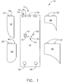
- FIG. 1 A first expression of the embodiment of figures 1-2 is an apparatus 10 for electroplating a workpiece 12.
- the apparatus 10 includes an unassembled electroplating anode assembly 14.
- the electroplating anode assembly 14 includes weldable first and second structural anode members 16 and 18.
- structural is meant substantially rigid.
- the first structural anode member 16 includes a positioning slot 20, and the second structural anode member 18 includes a positioning tab 22 disposable in the positioning slot 20.
- describing the apparatus as having a particular component means that the apparatus has at least one particular component (such as at least one electroplating anode assembly).
- describing a component as having a particular feature means that the component has at least one particular feature (such as at least one positioning slot).
- a second expression of the embodiment of figures 1-2 is an apparatus 10 for electroplating a workpiece 12.
- the apparatus 10 includes an electroplating anode assembly 14.
- the electroplating anode assembly 14 includes first and second structural anode members 16 and 18.
- the first structural anode member 16 includes a positioning slot 20.
- the second structural anode member 18 includes a positioning tab 22 disposed in the positioning slot 20.
- the first and second structural anode members 16 and 18 are welded together.
- the positioning slot 20 is a through slot.
- the first and second structural anode members 16 and 18 are substantially-rigid plate members.
- the electroplating anode assembly 14 also includes an active-anode mesh 24 supported by at least one of the first and second structural anode members 16 and 18.
- An active-anode mesh is an anode mesh which remains electrochemically active during electroplating of the workpiece.
- the workpiece 12 includes a workpiece surface portion 26 having a shape
- the activate anode mesh 24 has a shape which substantially conforms to the shape of the workpiece surface portion 26.
- the first and second structural anode members 16 and 18 are first and second structural inactive-anode members.
- a structural inactive-anode member is a structural anode member which builds up an anodic film and electrochemically passivates during electroplating of the workpiece.
- a third expression of the embodiment of figures 1-2 is an apparatus 10 for electroplating a workpiece 12.
- the apparatus 10 includes an unassembled electroplating anode assembly 14.
- the unassembled electroplating anode assembly 14 includes weldable first, second and third structural anode members 16, 18 and 28.
- the first structural anode member 16 includes positioning slots 20, 30, 32 and 34.
- the second and third structural anode members 18 and 28 each include two positioning tabs (tabs 22 and 36 for member 18 and tabs 38 and 40 for member 28).
- the positioning slots 20, 30, 32 and 34 and positioning tabs 22, 36, 38 and 40 are adapted to allow the two positioning tabs 22 and 36 of the second structural anode member 18 to be disposed in only a particular pair of positioning slots 20 and 30 and to allow the two positioning tabs 38 and 40 of the third structural anode member 28 to be disposed in only a separate particular pair of positioning slots 32 and 34.
- a fourth expression of the embodiment of figures 1-2 is an apparatus 10 for electroplating a workpiece 12.
- the apparatus 10 includes an electroplating anode assembly 14.
- the electroplating anode assembly 14 includes first, second and third structural anode members 16, 18 and 28.
- the second and third structural anode members 18 and 28 each include two positioning tabs (tabs 22 and 36 for member 18 and tabs 38 and 40 for member 28).
- the first structural anode member 16 includes a first set 42 of two positioning slots 20 and 30 and a second set 44 of two positioning slots 32 and 34.
- the two positioning tabs 22 and 36 of the second structural anode member 18 are matingly disposed one each in the two positioning slots 20 and 30 of the first set 42.
- the two positioning tabs 38 and 40 of the third structural anode member 28 are matingly disposed one each in the two positioning slots 32 and 34 of the second set 44.
- the first, second and third structural anode members 16, 18 and 28 are welded together.
- the distance between the two positioning slots 20 and 30 of the first set 42 is different from the distance between the two positioning slots 32 and 34 of the second set 44.
- the length of one of the two positioning slots 20 and 30 of the first set 42 is different from the length of any of the two positioning slots 32 and 34 of the second set 44.
- the length of any of the two positioning slots 20 and 30 of the first set 42 is different from the length of any of the two positioning slots 32 and 34 of the second set 44.
- a structural anode member can only be assembled in a unique pair of positioning slots of another structural anode member. In one variation a structural anode member can only have one orientation in a pair of positioning slots which are non-through slots.
- the workpiece 12 is a turbine airfoil.
- the electroplating anode assembly 14 also includes an active-anode mesh 24 supported by at least two of the first, second and third structural anode members 16, 18 and 28.
- the first, second and third structural anode members 16, 18 and 28 comprise titanium
- the active-anode mesh 24 consists essentially of platinum-clad niobium
- the turbine airfoil comprises a nickel-based superalloy.
- the structural anode members are machine cut by waterjet or laser.
- a first method of the invention is for making an electroplating anode assembly 14 and includes several steps.
- One step includes obtaining an electroplating-anode-assembly first structural anode member 16 having a positioning slot 20.
- Another step includes obtaining an electroplating-anode-assembly second structural anode member 18 having a positioning tab 22.
- An additional step includes disposing the positioning tab 22 in the positioning slot 20.
- a further step includes welding together the first and second structural anode members 16 and 18.
- a second method of the invention is for making an electroplating anode assembly 14 for electroplating a workpiece 12 and includes steps a) through f).
- Step a) includes obtaining an electroplating-anode-assembly first structural anode member 16 having a first set 42 of two positioning slots 20 and 30 and a second set 44 of positioning slots 32 and 34.
- Step b) includes obtaining an electroplating-anode-assembly second structural anode member 18 having two positioning tabs 22 and 36 matingly disposable one each in the two positioning slots 20 and 30 of the first set 42 but not the second set 44.
- Step c) includes obtaining an electroplating-anode-assembly third structural anode member 28 having two positioning tabs 38 and 40 matingly disposable one each in the two positioning slots 32 and 34 of the second set 44 but not the first set 42.
- Step d) includes matingly disposing the two positioning tabs 22 and 36 of the second structural anode member 18 in the two positioning slots 20 and 30 of the first set 42.
- Step e) includes matingly disposing the two positioning tabs 38 and 40 of the third structural anode member 28 in the two positioning slots 32 and 34 of the second set 44.
- Step f) includes welding together the first, second and third structural anode members 16, 18 and 28.
- a particular one of the two positioning tabs 22 and 36 of the second structural anode member 18 is disposable in only a particular one of the two positioning slots 20 and 30 of the first set 42, and, during step e), a particular one of the two positioning tabs 38 and 40 of the third structural anode member 28 is disposable in only a particular one of the two positioning slots 32 and 34 of the second set 44.
- the positioning slots 20, 30, 32 and 34 of the first and second sets 42 and 44 are through slots.
- the positioning tabs 22, 36, 38 and 40 of the second and third structural anode members 18 and 28 have free ends, and step f) includes welding the free ends of the matingly-disposed positioning tabs 22, 36, 38 and 40 of the second and third structural anode members 18 and 28 to the first structural anode member 16.
- the workpiece 12 is a turbine airfoil.
- the second method also includes the step of obtaining an active-anode mesh 24 having a shape substantially conforming to the shape of a surface portion of the turbine airfoil and the step of securing the active-anode mesh 24 to the second and third structural anode members 18 and 28.
- the active-anode mesh 24 is spot welded to the second and third structural anode members 18 and 28.
- the electroplating anode assembly 14 includes two additional structural anode members 46 and 48 having positioning tabs 50.
- the first structural anode member 16 has additional positioning slots 52, the positioning tabs 50 of the two additional structural anode members 46 and 48 are disposable/disposed in the additional positioning slots 52, the two additional structural anode members 46 and 48 are weldable/welded to the first structural anode member 16, and an additional active-anode mesh 54 is securable/secured to the two additional structural anode members 46 and 48 for electroplating a surface portion of an additional workpiece 56.
- the electroplating anode assembly 14 is copied a plurality of times with all of the electroplating anode assemblies supported by an anode rack (not shown) such as a titanium (or titanium alloy) anode rack.
- the first structural anode member 16 has attachment holes 58 for bolt-attachment to the anode rack.
- a cathode rack (not shown), such as a stainless steel cathode rack, supports a multiplicity of workpieces such as turbine airfoils.
- An electrolyte such as Pt(NH 3 ) 4 HPO 4 is in contact with the workpieces and the active anode meshes (such as 125DCX screen available from Vincent Metals Corporation of Rhode Island), and a rectifier applies a dc (direct current) voltage across the cathode and anode racks to electroplate the workpieces.
- electroplating anode assemblies for electroplating 16 turbine airfoils were fabricated within 12 hours using the principles of the invention compared to a fabrication time of up to 40 hours using conventional electroplating-anode-assembly techniques.
Landscapes
- Chemical & Material Sciences (AREA)
- Engineering & Computer Science (AREA)
- Materials Engineering (AREA)
- Chemical Kinetics & Catalysis (AREA)
- Electrochemistry (AREA)
- Metallurgy (AREA)
- Organic Chemistry (AREA)
- Mechanical Engineering (AREA)
- General Engineering & Computer Science (AREA)
- Electroplating Methods And Accessories (AREA)
Applications Claiming Priority (1)
| Application Number | Priority Date | Filing Date | Title |
|---|---|---|---|
| US10/926,739 US7494576B2 (en) | 2004-08-26 | 2004-08-26 | Electroplating apparatus and method for making an electroplating anode assembly |
Publications (3)
| Publication Number | Publication Date |
|---|---|
| EP1630259A2 true EP1630259A2 (de) | 2006-03-01 |
| EP1630259A3 EP1630259A3 (de) | 2011-06-15 |
| EP1630259B1 EP1630259B1 (de) | 2013-04-17 |
Family
ID=35414725
Family Applications (1)
| Application Number | Title | Priority Date | Filing Date |
|---|---|---|---|
| EP05255229.6A Ceased EP1630259B1 (de) | 2004-08-26 | 2005-08-25 | Apparatur zum Elektroplattieren und Methode zur Herstellung einer Anodeneinheit |
Country Status (3)
| Country | Link |
|---|---|
| US (1) | US7494576B2 (de) |
| EP (1) | EP1630259B1 (de) |
| JP (1) | JP4868795B2 (de) |
Families Citing this family (5)
| Publication number | Priority date | Publication date | Assignee | Title |
|---|---|---|---|---|
| US8636890B2 (en) * | 2011-09-23 | 2014-01-28 | General Electric Company | Method for refurbishing PtAl coating to turbine hardware removed from service |
| ES2859572T3 (es) | 2013-04-26 | 2021-10-04 | Howmet Corp | Electrodeposición del componente del perfil alar interno |
| CA2866479C (en) | 2013-12-20 | 2021-08-17 | Will N. Kirkendall | Internal turbine component electroplating |
| US10392948B2 (en) * | 2016-04-26 | 2019-08-27 | Honeywell International Inc. | Methods and articles relating to ionic liquid bath plating of aluminum-containing layers utilizing shaped consumable aluminum anodes |
| CN106283170B (zh) * | 2016-08-29 | 2018-05-29 | 中航动力股份有限公司 | 一种低压涡轮盘蓝色阳极腐蚀用辅助装置 |
Citations (1)
| Publication number | Priority date | Publication date | Assignee | Title |
|---|---|---|---|---|
| EP0336071A1 (de) | 1988-03-31 | 1989-10-11 | Eltech Systems Corporation | Massive Anode, die mosaikartig aus modularen Anoden besteht |
Family Cites Families (15)
| Publication number | Priority date | Publication date | Assignee | Title |
|---|---|---|---|---|
| US2116929A (en) * | 1935-04-23 | 1938-05-10 | Harshaw Chem Corp | Electrodeposition anode |
| US3407132A (en) * | 1965-06-16 | 1968-10-22 | Minnesota Mining & Mfg | Floating anode |
| US3300396A (en) * | 1965-11-24 | 1967-01-24 | Charles T Walker | Electroplating techniques and anode assemblies therefor |
| US3677929A (en) * | 1970-08-19 | 1972-07-18 | American Chem & Refining Co | Adjustable frame for thin sheet electrodes |
| JPS53130236A (en) * | 1977-04-20 | 1978-11-14 | Nippon Steel Corp | Anode structure in composite electrode |
| GB8821005D0 (en) * | 1988-09-07 | 1988-10-05 | Johnson Matthey Plc | Improvements in plating |
| JPH03285097A (ja) * | 1990-03-30 | 1991-12-16 | Mitsubishi Materials Corp | 電気めっき用陽極及び電気めっき方法 |
| TW197534B (de) * | 1991-03-21 | 1993-01-01 | Eltech Systems Corp | |
| JP3207909B2 (ja) * | 1992-02-07 | 2001-09-10 | ティーディーケイ株式会社 | 電気めっき方法および電気めっき用分割型不溶性電極 |
| US5344538A (en) * | 1993-01-11 | 1994-09-06 | Gould Inc. | Thin plate anode |
| TW318320B (de) * | 1995-08-07 | 1997-10-21 | Eltech Systems Corp | |
| JP3220101B2 (ja) * | 1999-02-03 | 2001-10-22 | トーホーテック株式会社 | 電解用電極 |
| US20030010649A1 (en) * | 2001-07-16 | 2003-01-16 | Waite Michael D. | Inert anode for electrochemical process |
| US20040231978A1 (en) * | 2001-09-19 | 2004-11-25 | White Tamara L | Electrode attachment to anode assembly |
| US6907666B2 (en) * | 2002-12-24 | 2005-06-21 | Delaware Capital Formation, Inc. | Method of assembly of vehicle body structure |
-
2004
- 2004-08-26 US US10/926,739 patent/US7494576B2/en not_active Expired - Lifetime
-
2005
- 2005-08-25 EP EP05255229.6A patent/EP1630259B1/de not_active Ceased
- 2005-08-25 JP JP2005243678A patent/JP4868795B2/ja not_active Expired - Fee Related
Patent Citations (1)
| Publication number | Priority date | Publication date | Assignee | Title |
|---|---|---|---|---|
| EP0336071A1 (de) | 1988-03-31 | 1989-10-11 | Eltech Systems Corporation | Massive Anode, die mosaikartig aus modularen Anoden besteht |
Also Published As
| Publication number | Publication date |
|---|---|
| US7494576B2 (en) | 2009-02-24 |
| EP1630259A3 (de) | 2011-06-15 |
| JP2006063451A (ja) | 2006-03-09 |
| EP1630259B1 (de) | 2013-04-17 |
| US20060042933A1 (en) | 2006-03-02 |
| JP4868795B2 (ja) | 2012-02-01 |
Similar Documents
| Publication | Publication Date | Title |
|---|---|---|
| EP1169495B1 (de) | Elektrochemisches abbeizen von turbinenschaufeln | |
| JP6126852B2 (ja) | ガスタービン部品のコーティング及びコーティング方法 | |
| EP1136593B1 (de) | Verfahren zur Erneuerung von Diffusionsschichten auf Superlegierungen | |
| US6605364B1 (en) | Coating article and method for repairing a coated surface | |
| EP3080338B1 (de) | Nickel-chrom-aluminium-verbundstoff durch elektrolytische abscheidung | |
| US20200291797A1 (en) | Electrodeposited nickel-chromium alloy | |
| US10487416B2 (en) | Electrochemical machining employing electrical voltage pulses to drive reduction and oxidation reactions | |
| US20110167634A1 (en) | Coated gas turbine engine component repair | |
| EP1630259B1 (de) | Apparatur zum Elektroplattieren und Methode zur Herstellung einer Anodeneinheit | |
| KR970011025A (ko) | 양극 전기 도금 셀 | |
| JP2757084B2 (ja) | チタン基剤金属支持体から金属被覆を剥離するための電解方法 | |
| JP7686699B2 (ja) | 電解加工の方法およびシステム | |
| JP6403250B2 (ja) | エアフォイル部品内部の電気めっき | |
| US20170081977A1 (en) | Method for selective aluminide diffusion coating removal | |
| US7771578B2 (en) | Method for producing of a galvanic coating | |
| RU2579717C2 (ru) | Способ удаления покрытия с обрабатываемых деталей | |
| EP1637629A2 (de) | Galvanisiereinrichtung und -verfahren zur Beschichtung eines Werkstücks | |
| JP2001055927A (ja) | タービン燃焼部用部材 | |
| JP2012057225A (ja) | メッキ前処理方法 | |
| CN109689916A (zh) | 热浸镀Al-Zn系钢板 | |
| CA2679308A1 (en) | Method for removing the coating of a component | |
| US20020003092A1 (en) | Process for the production of refractory metal plates and expanded metal grids platinized on one side | |
| JP2019195813A (ja) | ノズル及びその製造方法 | |
| WO2018170843A1 (en) | Electrochemical surface cleaning and plating | |
| JPH0881796A (ja) | 電解用電極 |
Legal Events
| Date | Code | Title | Description |
|---|---|---|---|
| PUAI | Public reference made under article 153(3) epc to a published international application that has entered the european phase |
Free format text: ORIGINAL CODE: 0009012 |
|
| AK | Designated contracting states |
Kind code of ref document: A2 Designated state(s): AT BE BG CH CY CZ DE DK EE ES FI FR GB GR HU IE IS IT LI LT LU LV MC NL PL PT RO SE SI SK TR |
|
| AX | Request for extension of the european patent |
Extension state: AL BA HR MK YU |
|
| PUAL | Search report despatched |
Free format text: ORIGINAL CODE: 0009013 |
|
| AK | Designated contracting states |
Kind code of ref document: A3 Designated state(s): AT BE BG CH CY CZ DE DK EE ES FI FR GB GR HU IE IS IT LI LT LU LV MC NL PL PT RO SE SI SK TR |
|
| AX | Request for extension of the european patent |
Extension state: AL BA HR MK YU |
|
| 17P | Request for examination filed |
Effective date: 20111215 |
|
| AKX | Designation fees paid |
Designated state(s): DE FR GB IT |
|
| GRAP | Despatch of communication of intention to grant a patent |
Free format text: ORIGINAL CODE: EPIDOSNIGR1 |
|
| RIC1 | Information provided on ipc code assigned before grant |
Ipc: C25D 17/00 20060101ALN20120123BHEP Ipc: C25D 17/10 20060101ALI20120123BHEP Ipc: C25D 17/12 20060101AFI20120123BHEP Ipc: F01D 5/28 20060101ALI20120123BHEP |
|
| GRAS | Grant fee paid |
Free format text: ORIGINAL CODE: EPIDOSNIGR3 |
|
| GRAA | (expected) grant |
Free format text: ORIGINAL CODE: 0009210 |
|
| AK | Designated contracting states |
Kind code of ref document: B1 Designated state(s): DE FR GB IT |
|
| REG | Reference to a national code |
Ref country code: GB Ref legal event code: FG4D |
|
| REG | Reference to a national code |
Ref country code: DE Ref legal event code: R096 Ref document number: 602005039106 Country of ref document: DE Effective date: 20130613 |
|
| PLBE | No opposition filed within time limit |
Free format text: ORIGINAL CODE: 0009261 |
|
| STAA | Information on the status of an ep patent application or granted ep patent |
Free format text: STATUS: NO OPPOSITION FILED WITHIN TIME LIMIT |
|
| 26N | No opposition filed |
Effective date: 20140120 |
|
| REG | Reference to a national code |
Ref country code: DE Ref legal event code: R097 Ref document number: 602005039106 Country of ref document: DE Effective date: 20140120 |
|
| REG | Reference to a national code |
Ref country code: FR Ref legal event code: PLFP Year of fee payment: 12 |
|
| REG | Reference to a national code |
Ref country code: FR Ref legal event code: PLFP Year of fee payment: 13 |
|
| PGFP | Annual fee paid to national office [announced via postgrant information from national office to epo] |
Ref country code: DE Payment date: 20170829 Year of fee payment: 13 Ref country code: GB Payment date: 20170829 Year of fee payment: 13 Ref country code: FR Payment date: 20170825 Year of fee payment: 13 Ref country code: IT Payment date: 20170823 Year of fee payment: 13 |
|
| REG | Reference to a national code |
Ref country code: DE Ref legal event code: R119 Ref document number: 602005039106 Country of ref document: DE |
|
| GBPC | Gb: european patent ceased through non-payment of renewal fee |
Effective date: 20180825 |
|
| PG25 | Lapsed in a contracting state [announced via postgrant information from national office to epo] |
Ref country code: IT Free format text: LAPSE BECAUSE OF NON-PAYMENT OF DUE FEES Effective date: 20180825 Ref country code: DE Free format text: LAPSE BECAUSE OF NON-PAYMENT OF DUE FEES Effective date: 20190301 |
|
| PG25 | Lapsed in a contracting state [announced via postgrant information from national office to epo] |
Ref country code: FR Free format text: LAPSE BECAUSE OF NON-PAYMENT OF DUE FEES Effective date: 20180831 |
|
| PG25 | Lapsed in a contracting state [announced via postgrant information from national office to epo] |
Ref country code: GB Free format text: LAPSE BECAUSE OF NON-PAYMENT OF DUE FEES Effective date: 20180825 |