EP1629903A1 - Apparatus for extracting liquid crystal by heating under reduced pressure and method thereof - Google Patents
Apparatus for extracting liquid crystal by heating under reduced pressure and method thereof Download PDFInfo
- Publication number
- EP1629903A1 EP1629903A1 EP05254992A EP05254992A EP1629903A1 EP 1629903 A1 EP1629903 A1 EP 1629903A1 EP 05254992 A EP05254992 A EP 05254992A EP 05254992 A EP05254992 A EP 05254992A EP 1629903 A1 EP1629903 A1 EP 1629903A1
- Authority
- EP
- European Patent Office
- Prior art keywords
- liquid crystal
- waste liquid
- crystal panel
- chamber
- heating
- Prior art date
- Legal status (The legal status is an assumption and is not a legal conclusion. Google has not performed a legal analysis and makes no representation as to the accuracy of the status listed.)
- Granted
Links
Images


Classifications
-
- G—PHYSICS
- G02—OPTICS
- G02F—OPTICAL DEVICES OR ARRANGEMENTS FOR THE CONTROL OF LIGHT BY MODIFICATION OF THE OPTICAL PROPERTIES OF THE MEDIA OF THE ELEMENTS INVOLVED THEREIN; NON-LINEAR OPTICS; FREQUENCY-CHANGING OF LIGHT; OPTICAL LOGIC ELEMENTS; OPTICAL ANALOGUE/DIGITAL CONVERTERS
- G02F1/00—Devices or arrangements for the control of the intensity, colour, phase, polarisation or direction of light arriving from an independent light source, e.g. switching, gating or modulating; Non-linear optics
- G02F1/01—Devices or arrangements for the control of the intensity, colour, phase, polarisation or direction of light arriving from an independent light source, e.g. switching, gating or modulating; Non-linear optics for the control of the intensity, phase, polarisation or colour
- G02F1/13—Devices or arrangements for the control of the intensity, colour, phase, polarisation or direction of light arriving from an independent light source, e.g. switching, gating or modulating; Non-linear optics for the control of the intensity, phase, polarisation or colour based on liquid crystals, e.g. single liquid crystal display cells
- G02F1/133—Constructional arrangements; Operation of liquid crystal cells; Circuit arrangements
- G02F1/1333—Constructional arrangements; Manufacturing methods
- G02F1/1341—Filling or closing of cells
-
- B—PERFORMING OPERATIONS; TRANSPORTING
- B01—PHYSICAL OR CHEMICAL PROCESSES OR APPARATUS IN GENERAL
- B01B—BOILING; BOILING APPARATUS ; EVAPORATION; EVAPORATION APPARATUS
- B01B1/00—Boiling; Boiling apparatus for physical or chemical purposes ; Evaporation in general
- B01B1/005—Evaporation for physical or chemical purposes; Evaporation apparatus therefor, e.g. evaporation of liquids for gas phase reactions
-
- B—PERFORMING OPERATIONS; TRANSPORTING
- B09—DISPOSAL OF SOLID WASTE; RECLAMATION OF CONTAMINATED SOIL
- B09B—DISPOSAL OF SOLID WASTE NOT OTHERWISE PROVIDED FOR
- B09B3/00—Destroying solid waste or transforming solid waste into something useful or harmless
- B09B3/40—Destroying solid waste or transforming solid waste into something useful or harmless involving thermal treatment, e.g. evaporation
-
- G—PHYSICS
- G02—OPTICS
- G02F—OPTICAL DEVICES OR ARRANGEMENTS FOR THE CONTROL OF LIGHT BY MODIFICATION OF THE OPTICAL PROPERTIES OF THE MEDIA OF THE ELEMENTS INVOLVED THEREIN; NON-LINEAR OPTICS; FREQUENCY-CHANGING OF LIGHT; OPTICAL LOGIC ELEMENTS; OPTICAL ANALOGUE/DIGITAL CONVERTERS
- G02F1/00—Devices or arrangements for the control of the intensity, colour, phase, polarisation or direction of light arriving from an independent light source, e.g. switching, gating or modulating; Non-linear optics
- G02F1/01—Devices or arrangements for the control of the intensity, colour, phase, polarisation or direction of light arriving from an independent light source, e.g. switching, gating or modulating; Non-linear optics for the control of the intensity, phase, polarisation or colour
- G02F1/13—Devices or arrangements for the control of the intensity, colour, phase, polarisation or direction of light arriving from an independent light source, e.g. switching, gating or modulating; Non-linear optics for the control of the intensity, phase, polarisation or colour based on liquid crystals, e.g. single liquid crystal display cells
-
- B—PERFORMING OPERATIONS; TRANSPORTING
- B09—DISPOSAL OF SOLID WASTE; RECLAMATION OF CONTAMINATED SOIL
- B09B—DISPOSAL OF SOLID WASTE NOT OTHERWISE PROVIDED FOR
- B09B2101/00—Type of solid waste
- B09B2101/02—Gases or liquids enclosed in discarded articles, e.g. aerosol cans or cooling systems of refrigerators
Definitions
- the present invention relates to an apparatus for extracting liquid crystal by heating under reduced pressure, to a method thereof, and to a liquid crystal display device, and more particularly, to an apparatus and a method which can extract liquid crystal from liquid crystal panels to be disposed of from liquid crystal panel manufacturing factories or liquid crystal panels used in image display devices or information display devices disposed in marketplaces, by heating under reduced pressure.
- liquid crystal panels are used in electric home appliances and information devices.
- the number of such liquid crystal panels in use is expected to increase rapidly with the advancement of information technology society in terms of the development of devices with low power consumption and slim size.
- a liquid crystal panel is structured in a manner such that liquid crystal mainly consisting of organic solvents is interposed between a pair of glass substrates on which transparent electrodes such as ITO (indium tin oxide) are deposited, and contacted surfaces of an outer periphery are sealed with an epoxy-based adhesive.
- transparent electrodes such as ITO (indium tin oxide) are deposited, and contacted surfaces of an outer periphery are sealed with an epoxy-based adhesive.
- Polarizing plates are attached to the outer surfaces of the glass substrates and organic materials such as a color filter and so on are disposed inside the glass substrates.
- the method is composed of the steps of carbonizing organic materials constituting the waste liquid crystal panel by disposing the waste liquid crystal panel in a heating furnace without breaking the waste liquid crystal panel, removing carbides from the glass of the liquid crystal panel, removing inorganic constituents from the glass of the liquid crystal panel by implementing a cleaning process using a strong acid solution, and removing the strong acid solution used in the process of removing the inorganic constituents from the glass of the liquid crystal panel.
- a temperature for implementing the reduced pressure heat treatment must be set to a temperature as high as from 200 to 800°C. Consequently, as the processing temperature is set to a high temperature in the range of 200 to 800°C, the evaporated liquid crystal is likely to be changed into harmful substances such as dioxins, PCB or the like, which is not preferable from the viewpoint of safety.
- An advantage of the invention is that it provides an apparatus for extracting liquid crystal by heating under reduced pressure which can easily raise the temperature of a waste liquid crystal panel and can lower the temperature of reduced pressure heat treatment to as low as the evaporation temperature of liquid crystal to efficiently recover liquid crystal with low energy consumption and a method thereof.
- An apparatus for extracting liquid crystal from a waste liquid crystal panel by heating under reduced pressure includes a chamber defining an inner space in which a waste liquid crystal panel is placed and having a heating unit that heats the inner space, a pressure-reducing unit that maintains the inner space under a pressure-reduced state, and a heat conducting unit provided separately from an inner wall of the chamber which generates a temperature for the reduced pressure heat treatment in the inner space, to heat and thereby weaken an opening-sealing material or a sealing material of the waste liquid crystal panel.
- the structure when extracting liquid crystal from the waste liquid crystal panel placed in the chamber by heating under reduced pressure, a temperature raise in the waste liquid crystal panel for ensuring breakage (or weakening) of the waste liquid crystal panel can be easily implemented, and a reduced pressure heat treatment temperature can be lowered as low as an evaporation temperature of liquid crystal. As a result, the liquid crystal is unlikely to be changed into harmful substances and can be recovered in a reliable manner.
- the waste liquid crystal panel is placed in the chamber to undergo a closed processing by heating under reduced pressure without the need of being broken, it is possible to safely recover liquid crystal.
- the heat conducting unit is a heat conductor which is connected to a heating source separate from a heating source of the heating unit that heats the inner wall of the chamber.
- the heat conductor which is connected to the separate heating source capable of being independently controlled is provided. Therefore, since the opening-sealing material or sealing material of the waste liquid crystal panel can be directly heated and weakened, the surrounding temperature in the chamber can be lowered as low as an evaporation temperature of liquid crystal, by which it is possible to remove the possibility of the extracted liquid crystal to be changed into harmful substances.
- the heat conducting unit is formed into a rod-shape such that, when a plurality of waste liquid crystal panels are arranged, the heat conducting unit can be brought into contact with opening-sealing materials or sealing materials of the plurality of waste liquid crystal panels.
- the heat conducting unit is formed into the rod-shape, when heating and weakening the waste liquid crystal panel, the plurality of waste liquid crystal panels can be placed on the rod-shaped heat conducting unit to undergo the reduced pressure heat treatment.
- the heat conducting unit is formed into a rod-shape such that, when a plurality of waste liquid crystal panels are arranged, the heat conducting unit can be brought into contact with sealing materials of openings of the waste liquid crystal panels, and at least a portion of a sectional shape of the heat conducting unit can conform to an outer surface of the sealing material of each opening.
- the heat conducting unit when weakening the sealing materials of the openings of the waste liquid crystal panels, since the heat conducting unit can conform to the outer surface of the sealing material of each opening, heat transfer to the sealing materials can be implemented in an efficient manner.
- the waste liquid crystal panel is sealed while not having an opening, and at least a portion of the opening-sealing material for sealing liquid crystal of the waste liquid crystal panel is applied adjacent to a periphery of the waste liquid crystal panel to easily receive heat from the heat conducting unit.
- the structure even in the case of the waste liquid crystal panel without an opening, since a portion of the opening-sealing material for sealing liquid crystal can efficiently receive heat from the heat conducting unit, it is possible to effectively weaken the waste liquid crystal panel without an opening.
- a method of extracting liquid crystal from a waste liquid crystal panel by heating under reduced pressure includes the steps of disposing a waste liquid crystal panel in a chamber which has a heating unit that heats an inner space defined in the chamber by the medium of an inner wall of the chamber, and weakening an opening-sealing material or a sealing material of the waste liquid crystal panel using a heat conducting unit provided separately from the inner wall of the chamber, when heating the waste liquid crystal panel by the medium of the inner wall while maintaining the inner space in a pressure-reduced state.
- a temperature raise in the waste liquid crystal panel can be easily implemented. Also, since a reduced pressure heat treatment temperature can be lowered as low as an evaporation temperature of liquid crystal, the liquid crystal is not changed into harmful substances and can be safely recovered.
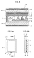
- FIG. 8 a typical waste liquid crystal panel 10 to be processed according to the invention is illustrated in FIG. 8.
- the waste liquid crystal panel 10 is one discharged from a liquid crystal panel manufacturing factory or obtained from an image display device or information display device whose lifetime has come to an end.
- the waste liquid crystal panel 10 shown in FIG. 8 is an active type liquid crystal panel such as a TFT liquid crystal panel.
- a passive type liquid crystal panel can also be appropriately processed according to the invention.
- the waste liquid crystal panel 10 has a pair of glass substrates 1a and 1b which are separated from each other by a predetermined distance. These glass substrates 1a and 1b are bonded to each other with an sealing material 7 such as an epoxy resin or the like which is applied along the peripheries of the glass substrates 1a and 1b between the inner surfaces thereof.
- the glass substrates 1a and 1b are properly separated by the predetermined distance due to the presence of a spacer 8, and liquid crystal 9 consisting of organic solvents is filled in the space which is defined between the glass substrates 1a and 1b and is sealed by the sealing material 7, thereby forming a liquid crystal layer.
- Polarizing plates 2 are attached to the outer surfaces of the glass substrates 1a and 1b with an adhesive.
- a polarizing plate 2 is disposed on the outer surface, and a color filter 3, an overcoat 4 formed with a transparent conductive layer 6, and an alignment layer 5 are disposed on the inner surface.
- a polarizing plate 2 is disposed on the outer surface, and a transparent thin conductive film 6 and an alignment layer 5 are disposed on the inner surface.
- the polarizing plates 2, the color filter 3 and the alignment layers 5 are formed of materials containing an organic material as a main constituent, and the transparent thin conductive film 6 is formed of a film containing an indium constituent or the like.
- the reference numeral 11 designates a switching element which is made of metal.
- FIG. 9A shows the pair of glass substrates 1a and 1b, the sealing material 7 for holding the liquid crystal 9 between the glass substrates 1a and 1b, and an opening-sealing material 7b for sealing an opening 7a defined in the sealing material 7, which constitute the main part of the waste liquid crystal panel 10 shown in FIG. 8.
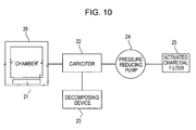
- FIG. 10 is a view schematically illustrating construction of a system for processing liquid crystal of a waste liquid crystal panel according to the invention.
- the system includes a chamber 20, a pressure-reducing pump 24, a capacitor 22, a decomposing device 23 and an activated charcoal filter 25.
- the chamber 20 defines an inner space in which the waste liquid crystal panel 10 is disposed and has a heating unit 21 for heating the inner space.
- the pressure-reducing pump 24 is provided at the discharge side of the chamber 20 and serves as the pressure-reducing means for reducing the pressure in the chamber 20.
- the capacitor 22 is disposed between the chamber 20 and the pressure-reducing pump 24.
- the capacitor 22 condenses the liquid crystal which is evaporated and thereby extracted by heating under reduced pressure of the waste liquid crystal panel 10 in the chamber 20 to recover the liquid crystal from other gases.
- the decomposing device 23 decomposes the liquid crystal condensed and separated by the capacitor 22 to make the liquid crystal harmless.
- the activated charcoal filter 25 cleans the remaining gas after the liquid crystal is separated from other gases, and
- FIG. 1 is a perspective view showing the chamber in an apparatus for extracting liquid crystal by heating under reduced pressure in accordance with a first embodiment of the invention
- FIG. 2 is a perspective view in which a tray and heater wires disposed in the chamber shown in FIG. 1 are shown in a partially cutaway fashion.
- FIG. 1 shows the outer appearance of the chamber 20 in which the reduced pressure heat treatment is implemented, in the apparatus for extracting liquid crystal from the waste liquid crystal panels 10 by heating under reduced pressure.
- the chamber 20 has a heating unit (not shown but indicated by the reference numeral 21 in FIG. 10) which serves as heating means for evaporating the liquid crystal from waste liquid crystal panels 10 placed in the inner space of the chamber 20.
- the chamber 20 With the chamber 20 maintained in a pressure-reduced state by using the pressure-reducing pump as pressure-reducing means, the chamber 20 heats the waste liquid crystal panels 10.
- a tray 28 for holding the plurality of waste liquid crystal panels 10 and the heater wires 27 which serve as heat conducting means for locally heating the opening-sealing material or the sealing material of each waste liquid crystal panel 10 are disposed in the chamber 20.
- the inner wall defining the inner space of the chamber 20 is made of a metallic material which has an excellent heat conductivity.
- the inner wall is heated by the heating unit (indicated by the reference numeral 21 in FIG. 10) which is disposed in the inner wall of the chamber 20, to serve as a main heating source for evaporating the liquid crystal of the waste liquid crystal panels 10. Accordingly, the inner wall of the chamber is maintained at a temperature appropriate for the reduced pressure heat treatment.
- the inner space of the chamber 20 in which the reduced pressure heat treatment is implemented is reduced in pressure to a value in the range of 0.01 to 10 Kpa. While a processing temperature will be described later, in the embodiment of the invention, the processing temperature can be set at about 150°C which corresponds to the evaporation temperature of the liquid crystal.
- the chamber 20 substantially has a box shape such as a rectangular parallelepiped or a regular hexahedron.
- a cover which can be opened and tightly closed is provided on the front surface of the chamber 20.
- a heat-resistant glass is provided to the cover so that the inner space of the chamber 20 can be observed.
- the inner space of the chamber 20 is divided, for example, into two upper and lower compartments.
- At least one tray 28 capable of holding a predetermined number of waste liquid crystal panels 10 can be disposed in each compartment.
- the tray 28 is formed of an insulating material having heat resistance and has the shape of a frame or a basket.
- FIG. 2 shows the tray 28 for receiving the waste liquid crystal panels 10 and a structure which is disposed in the tray 28 to bring the opening 7a of the waste liquid crystal panels 10 into contact with the heater wires 27 which are heat conductors.
- partitioning plates or partitioning line members are arranged in the longitudinal and transverse directions to hold the waste liquid crystal panels 10 apart from one another.
- the heater wires 27 serving as the heat conducting means are arranged parallel to each other below the tray 28. Both ends of each heater wire 27 pass through the inner wall of the chamber 20 and are connected to a separate heating source 26 which is provided outside the chamber 20 and is different from the heating unit.
- the tray 28 is formed of an insulating material having a heat resistance.
- the tray 28 has a structure capable of holding the heater wires 27 inside the chamber. Both ends of the each heater wire 27 pass through one side of the wall of the tray 28 to be connected to the separate heating source 26 which is provided outside (or inside) the chamber 20 and is different from the heating unit.
- the set of the tray 28 and the heater wires 27 may be fixedly disposed in the chamber 20, or the heater wires 27 may be detachably integrated with the tray 28 by providing connector means on the inner wall of the chamber 20.
- each waste liquid crystal panel 10 When disposing the waste liquid crystal panels 10 one by one into the partitioned spaces of the tray 28 which has the frame or basket-shaped configuration, each waste liquid crystal panel 10 is inserted into each partitioned space with the opening-sealing material 7b of the opening 7a (see FIG. 3 or FIG. 9) of the waste liquid crystal panel 10 facing downward, so that the opening-sealing material 7b of the waste liquid crystal panel 10 can be brought into contact with the outer peripheral surface of the heater wire 27 which is disposed below the tray 28.
- the opening-sealing material 7b is made of resin such as acryl resin, and due to this fact, the opening-sealing material 7b has a decomposition temperature which is lower than that of the sealing material 7 formed of epoxy resin or the like.
- the heater wire 27 may be formed of a wire rod which has a high electric resistance so that a current can flow through the wire rod for the purpose of heating the waste liquid crystal panel 10.
- the sealing resin By heating only the sealed part of the waste liquid crystal panel 10, the sealing resin is weakened and cracks are formed in the sealing resin. As a consequence, leakage paths are formed in the sealed portion as shown in FIG. 3, and the liquid crystal can be evaporated into the inner space of the chamber 20 through the leakage paths.
- the liquid crystal evaporated into the inner space of the chamber 20 is condensed and separated by the capacitor 22 shown in FIG. 10 and then supplied to the decomposing device 23.
- FIG. 3 shows a state in which the sealed portion of the liquid crystal panel having the opening shown in Fig. 9 is heated by the heater wire 27. Since the sealed portion is heated with the heater wire 27 brought into contact only with the opening-sealing material 7b, the temperature of the inner space of the chamber 20 is not significantly increased and corresponds to the evaporation temperature of the liquid crystal. That is to say, by forming cracks (causing leakage) in the sealed portion of the waste liquid crystal panel 10 through local heating using the heater wire 27, the liquid crystal filled between the glass substrates 1a and 1b can be evaporated through the leakage paths.
- FIG. 4 shows various sectional shapes of the heater wire for heating the opening-sealing material 7b.
- FIG. 4A shows a sectional shape of the heater wire 27' which has on the upper surface thereof a curved portion to conform to the middle portion of the opening-sealing material 7b having a curved contour.
- FIG. 4B shows a sectional shape of the heater wire 27" which has on the upper surface thereof a curved portion and plane portions formed at both sides of the curved portion to conform to the entire portion of the opening-sealing material 7b having a curved contour and to extend slightly beyond both widthwise ends of the curved opening-sealing material 7b to thereby be brought into partial contact with the glass substrates.
- FIG. 4C shows a sectional shape of the heater wire 27' ' ' which is rectangular or square and has a plane upper surface. All these heater wires are formed to extend in the shape of a rail so as to simultaneously heat the plurality of waste liquid crystal panels.
- a heating source for the heater wires 27 serving as heat conductors is gained from the main heating source, that is, the inner wall of the chamber 20 which is heated by the heating unit 21.
- the liquid crystal is likely to be changed into harmful substances, which is not preferable from the viewpoint of recycling and safety.
- the method (B) is adopted as a method of raising the temperature of the heater wires 27, the method (B) is adopted.
- the invention is not limited to this case in which the sealed portion is necessarily broken (weakened).
- the invention may be constructed in such a manner that the sealing material 7 is heated by a heat conductor (as shown by the two-dot chain line) 27a, 27b or 27c which is disposed around the periphery of the waste liquid crystal panel 10, to be broken or weakened as shown in FIG. 3.
- the sealing material 7 is generally formed of epoxy-based resin
- the decomposition temperature of the sealing material 7 in the pressure-reduced state is T3'
- the sealing material 7 is heated by the heat conductor (as shown by the two-dot chain line) 27a, 27b or 27c which is disposed around the periphery of the waste liquid crystal panel 10, to be broken or weakened, as can be readily seen from FIG. 5, for example, the interface between the glass substrate 1b and the sealing material 7 serves as a leakage surface, from which the leakage path of the liquid crystal 9 is formed.
- the heat conductor as shown by the two-dot chain line
- the temperature of the waste liquid crystal panel can be easily raised, and a processing temperature can be lowered. Also, due to the closed processing in which the waste liquid crystal panel is placed in the chamber 20 without being broken to undergo reduced pressure heat treatment, it is possible to safely extract the liquid crystal.
- the waste liquid crystal panels 10 may be no-opening type liquid crystal panels which do not have openings.
- the sealing material 7 is applied in the shape of a closed loop onto one glass substrate 1a of the two glass substrates at a position which is separated from the periphery of the glass substrate by a predetermined distance, and then, an appropriate amount of liquid crystal 9 is dropped onto the space surrounded by the sealing material 7 using a dispenser (not shown).
- the other glass substrate 1b is placed on the one glass substrate 1a so that the one and the other glass substrates are bonded to each other by the sealing material 7. Therefore, in the no-opening type liquid crystal panels, the opening which is sealed by the opening-sealing material 7b as shown in FIGs. 3 and 9 does not exist.
- At least a portion of the patterned shape of the sealing material 7 is applied to be more adjacent to the periphery of the waste liquid crystal panel as shown in FIG. 6A when compared with the conventional patterned shape of the sealing material 7 as shown in FIG. 6B.
- the sealing material 7 is applied to the liquid crystal panel in the shape of a frame to seal the liquid crystal, at least a portion (indicated by the reference numeral 7c) of the sealing material 7 is applied to project toward the peripheries of the two glass substrates 1a and 1b which constitute the liquid crystal panel.
- a heater wire 27 (shown by the two-dot chain line) can be brought into contact with the outer surface of the projecting portion 7c to locally heat and break (weaken) the projecting portion 7c, so that the liquid crystal filled in the space between the glass substrates 1a and 1b can be extracted into the inner space of the chamber in which the reduced pressure heat treatment is implemented.
- a plurality of projecting portions 7c may be formed in the sealing material 7.
- FIG. 7 is an explanatory view showing one of the processes for manufacturing the no-opening type liquid crystal panels shown in FIG. 6A.
- two large-sized glass substrates are prepared, the sealing material 7 is applied onto one large-sized glass substrate to form a plurality of sealing patterns each having the projecting portion 7c so that the sealing patterns are arranged in longitudinal and transverse directions in correspondence to a plurality of liquid crystal panels to be manufactured.
- the other large-sized glass substrate is bonded to the one large-sized glass substrate to obtain a mother substrate 30.
- the mother substrate 30 is cut into the plurality of liquid crystal panels using a dicing device.
- the liquid crystal can be extracted by locally breaking (weakening) a portion of the waste liquid crystal panel, in a state in which the temperature of the inner wall of the chamber, that is, the temperature governing the inner space of the chamber can be suppressed to about 150°C capable of evaporating the liquid crystal, the liquid crystal can be extracted. Accordingly, the possibility of the liquid crystal being changed into harmful substances (such as dioxins and PCB) is eliminated, and the liquid crystal can be extracted without being changed into the harmful substances.
- harmful substances such as dioxins and PCB
- liquid crystal can be extracted while preventing generation of harmful substances. Therefore, safety and reliability are improved when extracting liquid crystal. Further, the liquid crystal can be made harmless, and a processing system having a high grade of safety can be realized.
Landscapes
- Physics & Mathematics (AREA)
- Nonlinear Science (AREA)
- Chemical & Material Sciences (AREA)
- Crystallography & Structural Chemistry (AREA)
- Environmental & Geological Engineering (AREA)
- Engineering & Computer Science (AREA)
- Thermal Sciences (AREA)
- General Physics & Mathematics (AREA)
- Optics & Photonics (AREA)
- Chemical Kinetics & Catalysis (AREA)
- Mathematical Physics (AREA)
- Processing Of Solid Wastes (AREA)
- Liquid Crystal (AREA)
Abstract
Description
- The present invention relates to an apparatus for extracting liquid crystal by heating under reduced pressure, to a method thereof, and to a liquid crystal display device, and more particularly, to an apparatus and a method which can extract liquid crystal from liquid crystal panels to be disposed of from liquid crystal panel manufacturing factories or liquid crystal panels used in image display devices or information display devices disposed in marketplaces, by heating under reduced pressure.
- Recently, as the amount of domestic waste and industrial waste has been increasing, there has been increasing demand for means for rendering the waste harmless, in order to suppress the increase in the amount of wastes and to prevent environmental pollution caused by the waste.
- In order to meet the demand, efforts have been made to decrease the amount of waste by promoting recycling of industrial waste disposed of from factories and domestic waste such as electric home appliances, information devices or the like disposed of from homes and offices.
- In this regard, for example, liquid crystal panels are used in electric home appliances and information devices. The number of such liquid crystal panels in use is expected to increase rapidly with the advancement of information technology society in terms of the development of devices with low power consumption and slim size.
- Generally, a liquid crystal panel is structured in a manner such that liquid crystal mainly consisting of organic solvents is interposed between a pair of glass substrates on which transparent electrodes such as ITO (indium tin oxide) are deposited, and contacted surfaces of an outer periphery are sealed with an epoxy-based adhesive. Polarizing plates are attached to the outer surfaces of the glass substrates and organic materials such as a color filter and so on are disposed inside the glass substrates.
- Apparatuses for recovering glass or rare metals from liquid crystal panels have already been disclosed. An apparatus and a method of processing waste liquid crystal panels in such a manner that a waste liquid crystal panel is placed in a reaction furnace without being broken, and subsequently heated in the reaction furnace under a pressure-reduced state; thus, liquid crystal which constitutes the waste liquid crystal panel and a portion of solid organic materials which are disposed on the inner and outer surfaces of the glass substrates are evaporated, and the remaining portion of the solid organic materials are carbonized has been proposed (for example, see Japanese Unexamined Patent Application Publication No. 2004-230229).
- Also, it is conceivable to provide a method of recovering glass of a liquid crystal panel from a waste liquid crystal panel. The method is composed of the steps of carbonizing organic materials constituting the waste liquid crystal panel by disposing the waste liquid crystal panel in a heating furnace without breaking the waste liquid crystal panel, removing carbides from the glass of the liquid crystal panel, removing inorganic constituents from the glass of the liquid crystal panel by implementing a cleaning process using a strong acid solution, and removing the strong acid solution used in the process of removing the inorganic constituents from the glass of the liquid crystal panel.
- However, in the above-described methods, when the waste liquid crystal panel is heated under a reduced pressure, it is difficult to raise the temperature of the inside of the furnace and the temperature of the liquid crystal panel being processed. In order to extract liquid crystal from the liquid crystal panel by heating under a reduced pressure which is similar to a vacuum condition, it is necessary to break (weaken) a resin portion, but the temperature for ensuring the breakage of the resin portion is higher than the temperature for extracting liquid crystal. That is to say, the temperature required for evaporating liquid crystal under a pressure-reduced state is 150°C, whereas a temperature required for weakening the resin portion is 200 to 800°C. Therefore, a temperature for implementing the reduced pressure heat treatment must be set to a temperature as high as from 200 to 800°C.
Consequently, as the processing temperature is set to a high temperature in the range of 200 to 800°C, the evaporated liquid crystal is likely to be changed into harmful substances such as dioxins, PCB or the like, which is not preferable from the viewpoint of safety. - An advantage of the invention is that it provides an apparatus for extracting liquid crystal by heating under reduced pressure which can easily raise the temperature of a waste liquid crystal panel and can lower the temperature of reduced pressure heat treatment to as low as the evaporation temperature of liquid crystal to efficiently recover liquid crystal with low energy consumption and a method thereof.
- An apparatus for extracting liquid crystal from a waste liquid crystal panel by heating under reduced pressure according to an aspect of the invention includes a chamber defining an inner space in which a waste liquid crystal panel is placed and having a heating unit that heats the inner space, a pressure-reducing unit that maintains the inner space under a pressure-reduced state, and a heat conducting unit provided separately from an inner wall of the chamber which generates a temperature for the reduced pressure heat treatment in the inner space, to heat and thereby weaken an opening-sealing material or a sealing material of the waste liquid crystal panel.
- According to the structure, when extracting liquid crystal from the waste liquid crystal panel placed in the chamber by heating under reduced pressure, a temperature raise in the waste liquid crystal panel for ensuring breakage (or weakening) of the waste liquid crystal panel can be easily implemented, and a reduced pressure heat treatment temperature can be lowered as low as an evaporation temperature of liquid crystal. As a result, the liquid crystal is unlikely to be changed into harmful substances and can be recovered in a reliable manner. In this aspect of the invention, as the waste liquid crystal panel is placed in the chamber to undergo a closed processing by heating under reduced pressure without the need of being broken, it is possible to safely recover liquid crystal.
- In the apparatus for extracting liquid crystal by heating under reduced pressure according to another aspect of the invention, the heat conducting unit is a heat conductor which is connected to a heating source separate from a heating source of the heating unit that heats the inner wall of the chamber.
- According to the structure, not a heat conductor for transferring heat of the inner wall of the chamber generated by the heating unit constituting the chamber, but the heat conductor which is connected to the separate heating source capable of being independently controlled is provided. Therefore, since the opening-sealing material or sealing material of the waste liquid crystal panel can be directly heated and weakened, the surrounding temperature in the chamber can be lowered as low as an evaporation temperature of liquid crystal, by which it is possible to remove the possibility of the extracted liquid crystal to be changed into harmful substances.
- In the apparatus for extracting liquid crystal by heating under reduced pressure according to another aspect of the invention, the heat conducting unit is formed into a rod-shape such that, when a plurality of waste liquid crystal panels are arranged, the heat conducting unit can be brought into contact with opening-sealing materials or sealing materials of the plurality of waste liquid crystal panels.
- According to the structure, because the heat conducting unit is formed into the rod-shape, when heating and weakening the waste liquid crystal panel, the plurality of waste liquid crystal panels can be placed on the rod-shaped heat conducting unit to undergo the reduced pressure heat treatment.
- In the apparatus for extracting liquid crystal by heating under reduced pressure according to another aspect of the invention, the heat conducting unit is formed into a rod-shape such that, when a plurality of waste liquid crystal panels are arranged, the heat conducting unit can be brought into contact with sealing materials of openings of the waste liquid crystal panels, and at least a portion of a sectional shape of the heat conducting unit can conform to an outer surface of the sealing material of each opening.
- According to the structure, when weakening the sealing materials of the openings of the waste liquid crystal panels, since the heat conducting unit can conform to the outer surface of the sealing material of each opening, heat transfer to the sealing materials can be implemented in an efficient manner.
- In the apparatus for extracting liquid crystal by heating under reduced pressure according to another aspect of the invention, the waste liquid crystal panel is sealed while not having an opening, and at least a portion of the opening-sealing material for sealing liquid crystal of the waste liquid crystal panel is applied adjacent to a periphery of the waste liquid crystal panel to easily receive heat from the heat conducting unit.
- According to the structure, even in the case of the waste liquid crystal panel without an opening, since a portion of the opening-sealing material for sealing liquid crystal can efficiently receive heat from the heat conducting unit, it is possible to effectively weaken the waste liquid crystal panel without an opening.
- A method of extracting liquid crystal from a waste liquid crystal panel by heating under reduced pressure according to another aspect of the invention includes the steps of disposing a waste liquid crystal panel in a chamber which has a heating unit that heats an inner space defined in the chamber by the medium of an inner wall of the chamber, and weakening an opening-sealing material or a sealing material of the waste liquid crystal panel using a heat conducting unit provided separately from the inner wall of the chamber, when heating the waste liquid crystal panel by the medium of the inner wall while maintaining the inner space in a pressure-reduced state.
- According to the structure, when implementing reduced pressure heat treatment, a temperature raise in the waste liquid crystal panel can be easily implemented. Also, since a reduced pressure heat treatment temperature can be lowered as low as an evaporation temperature of liquid crystal, the liquid crystal is not changed into harmful substances and can be safely recovered.
- The invention will be described with reference to the accompanying drawings, wherein like numbers reference like elements, and wherein:
- FIG. 1 is a perspective view showing a chamber in an apparatus for extracting liquid crystal by heating under reduced pressure in accordance with a first embodiment of the invention;
- FIG. 2 is a perspective view in which a tray and heater wires disposed in the chamber shown in FIG. 1 are partially broken-out;
- FIG. 3 is an explanatory view showing a state in which an opening of an liquid crystal panel with an opening is heated by a heater wire to cause leakage of liquid crystal;
- FIG. 4 is of cross-sectional views showing sectional shapes of the heater wire;
- FIG. 5 is a view showing a portion which is likely to leak when an opening-sealing material shown in FIG. 3 is heated by the heater wire;
- FIG. 6 is of views showing no-opening type liquid crystal panels in an apparatus for extracting liquid crystal by heating under reduced pressure in accordance with a second embodiment of the invention;
- FIG. 7 is an explanatory view showing one of the processes for manufacturing the no-opening type liquid crystal panels shown in FIG. 6;
- FIG. 8 is a longitudinal cross-sectional view showing a conventional liquid crystal panel;
- FIG. 9 is of views showing an opened sealing type liquid crystal panel; and
- FIG. 10 is a view schematically illustrating a construction of a system for processing liquid crystal of a waste liquid crystal panel according to the invention.
- Hereafter, the embodiments of the invention will be described with reference to the accompanying drawings. First, a typical waste
liquid crystal panel 10 to be processed according to the invention is illustrated in FIG. 8. The wasteliquid crystal panel 10 is one discharged from a liquid crystal panel manufacturing factory or obtained from an image display device or information display device whose lifetime has come to an end. The wasteliquid crystal panel 10 shown in FIG. 8 is an active type liquid crystal panel such as a TFT liquid crystal panel. Of course, it is to be readily understood that a passive type liquid crystal panel can also be appropriately processed according to the invention. The wasteliquid crystal panel 10 has a pair ofglass substrates glass substrates material 7 such as an epoxy resin or the like which is applied along the peripheries of theglass substrates - The
glass substrates spacer 8, andliquid crystal 9 consisting of organic solvents is filled in the space which is defined between theglass substrates material 7, thereby forming a liquid crystal layer. Polarizingplates 2 are attached to the outer surfaces of theglass substrates glass substrate 1a, a polarizingplate 2 is disposed on the outer surface, and a color filter 3, an overcoat 4 formed with a transparent conductive layer 6, and an alignment layer 5 are disposed on the inner surface. In theother glass substrate 1b, a polarizingplate 2 is disposed on the outer surface, and a transparent thin conductive film 6 and an alignment layer 5 are disposed on the inner surface. - The polarizing
plates 2, the color filter 3 and the alignment layers 5 are formed of materials containing an organic material as a main constituent, and the transparent thin conductive film 6 is formed of a film containing an indium constituent or the like. Thereference numeral 11 designates a switching element which is made of metal. - FIG. 9A shows the pair of
glass substrates material 7 for holding theliquid crystal 9 between theglass substrates material 7b for sealing an opening 7a defined in the sealingmaterial 7, which constitute the main part of the wasteliquid crystal panel 10 shown in FIG. 8. FIG. 9B is a cross-sectional view taken along the line IXB-IXB of FIG. 9A, in which L1 = 0.5 mm and L2 = 5 to 10 µm. - FIG. 10 is a view schematically illustrating construction of a system for processing liquid crystal of a waste liquid crystal panel according to the invention. The system includes a
chamber 20, a pressure-reducingpump 24, acapacitor 22, adecomposing device 23 and an activatedcharcoal filter 25. Thechamber 20 defines an inner space in which the wasteliquid crystal panel 10 is disposed and has aheating unit 21 for heating the inner space. The pressure-reducingpump 24 is provided at the discharge side of thechamber 20 and serves as the pressure-reducing means for reducing the pressure in thechamber 20. Thecapacitor 22 is disposed between thechamber 20 and the pressure-reducingpump 24. Thecapacitor 22 condenses the liquid crystal which is evaporated and thereby extracted by heating under reduced pressure of the wasteliquid crystal panel 10 in thechamber 20 to recover the liquid crystal from other gases. The decomposingdevice 23 decomposes the liquid crystal condensed and separated by thecapacitor 22 to make the liquid crystal harmless. The activatedcharcoal filter 25 cleans the remaining gas after the liquid crystal is separated from other gases, and then discharges the gas. - FIG. 1 is a perspective view showing the chamber in an apparatus for extracting liquid crystal by heating under reduced pressure in accordance with a first embodiment of the invention, and FIG. 2 is a perspective view in which a tray and heater wires disposed in the chamber shown in FIG. 1 are shown in a partially cutaway fashion.
- FIG. 1 shows the outer appearance of the
chamber 20 in which the reduced pressure heat treatment is implemented, in the apparatus for extracting liquid crystal from the wasteliquid crystal panels 10 by heating under reduced pressure. Thechamber 20 has a heating unit (not shown but indicated by thereference numeral 21 in FIG. 10) which serves as heating means for evaporating the liquid crystal from wasteliquid crystal panels 10 placed in the inner space of thechamber 20. With thechamber 20 maintained in a pressure-reduced state by using the pressure-reducing pump as pressure-reducing means, thechamber 20 heats the wasteliquid crystal panels 10. Atray 28 for holding the plurality of wasteliquid crystal panels 10 and theheater wires 27 which serve as heat conducting means for locally heating the opening-sealing material or the sealing material of each wasteliquid crystal panel 10 are disposed in thechamber 20. - The inner wall defining the inner space of the
chamber 20 is made of a metallic material which has an excellent heat conductivity. The inner wall is heated by the heating unit (indicated by thereference numeral 21 in FIG. 10) which is disposed in the inner wall of thechamber 20, to serve as a main heating source for evaporating the liquid crystal of the wasteliquid crystal panels 10. Accordingly, the inner wall of the chamber is maintained at a temperature appropriate for the reduced pressure heat treatment. The inner space of thechamber 20 in which the reduced pressure heat treatment is implemented is reduced in pressure to a value in the range of 0.01 to 10 Kpa. While a processing temperature will be described later, in the embodiment of the invention, the processing temperature can be set at about 150°C which corresponds to the evaporation temperature of the liquid crystal. - The
chamber 20 substantially has a box shape such as a rectangular parallelepiped or a regular hexahedron. A cover which can be opened and tightly closed is provided on the front surface of thechamber 20. A heat-resistant glass is provided to the cover so that the inner space of thechamber 20 can be observed. The inner space of thechamber 20 is divided, for example, into two upper and lower compartments. At least onetray 28 capable of holding a predetermined number of wasteliquid crystal panels 10 can be disposed in each compartment. Thetray 28 is formed of an insulating material having heat resistance and has the shape of a frame or a basket. - FIG. 2 shows the
tray 28 for receiving the wasteliquid crystal panels 10 and a structure which is disposed in thetray 28 to bring theopening 7a of the wasteliquid crystal panels 10 into contact with theheater wires 27 which are heat conductors. - Inside the
tray 28, as shown by the two-dot chain lines E and F in FIG. 2, partitioning plates or partitioning line members are arranged in the longitudinal and transverse directions to hold the wasteliquid crystal panels 10 apart from one another. Theheater wires 27 serving as the heat conducting means are arranged parallel to each other below thetray 28. Both ends of eachheater wire 27 pass through the inner wall of thechamber 20 and are connected to aseparate heating source 26 which is provided outside thechamber 20 and is different from the heating unit. - The
tray 28 is formed of an insulating material having a heat resistance. Thetray 28 has a structure capable of holding theheater wires 27 inside the chamber. Both ends of the eachheater wire 27 pass through one side of the wall of thetray 28 to be connected to theseparate heating source 26 which is provided outside (or inside) thechamber 20 and is different from the heating unit. The set of thetray 28 and theheater wires 27 may be fixedly disposed in thechamber 20, or theheater wires 27 may be detachably integrated with thetray 28 by providing connector means on the inner wall of thechamber 20. When thetray 28 and theheater wires 27 are detachably constructed, workability can be improved when disposing the plurality of wasteliquid crystal panels 10 in thetray 28. - When disposing the waste
liquid crystal panels 10 one by one into the partitioned spaces of thetray 28 which has the frame or basket-shaped configuration, each wasteliquid crystal panel 10 is inserted into each partitioned space with the opening-sealingmaterial 7b of theopening 7a (see FIG. 3 or FIG. 9) of the wasteliquid crystal panel 10 facing downward, so that the opening-sealingmaterial 7b of the wasteliquid crystal panel 10 can be brought into contact with the outer peripheral surface of theheater wire 27 which is disposed below thetray 28. The opening-sealingmaterial 7b is made of resin such as acryl resin, and due to this fact, the opening-sealingmaterial 7b has a decomposition temperature which is lower than that of the sealingmaterial 7 formed of epoxy resin or the like. - As heat needed for heating is transferred to the
heater wires 27 through any heating source (themain heating source 21 or the separate heating source 26), heat is directly transferred to the opening-sealingmaterials 7b of theopening 7a of the wasteliquid crystal panels 10 respectively placed in the partitioned spaces, whereby the opening-sealingmaterials 7b are heated. Theheater wire 27 may be formed of a wire rod which has a high electric resistance so that a current can flow through the wire rod for the purpose of heating the wasteliquid crystal panel 10. - By heating only the sealed part of the waste
liquid crystal panel 10, the sealing resin is weakened and cracks are formed in the sealing resin. As a consequence, leakage paths are formed in the sealed portion as shown in FIG. 3, and the liquid crystal can be evaporated into the inner space of thechamber 20 through the leakage paths. The liquid crystal evaporated into the inner space of thechamber 20 is condensed and separated by thecapacitor 22 shown in FIG. 10 and then supplied to the decomposingdevice 23. - FIG. 3 shows a state in which the sealed portion of the liquid crystal panel having the opening shown in Fig. 9 is heated by the
heater wire 27. Since the sealed portion is heated with theheater wire 27 brought into contact only with the opening-sealingmaterial 7b, the temperature of the inner space of thechamber 20 is not significantly increased and corresponds to the evaporation temperature of the liquid crystal. That is to say, by forming cracks (causing leakage) in the sealed portion of the wasteliquid crystal panel 10 through local heating using theheater wire 27, the liquid crystal filled between theglass substrates - FIG. 4 shows various sectional shapes of the heater wire for heating the opening-sealing
material 7b. FIG. 4A shows a sectional shape of the heater wire 27' which has on the upper surface thereof a curved portion to conform to the middle portion of the opening-sealingmaterial 7b having a curved contour. FIG. 4B shows a sectional shape of theheater wire 27" which has on the upper surface thereof a curved portion and plane portions formed at both sides of the curved portion to conform to the entire portion of the opening-sealingmaterial 7b having a curved contour and to extend slightly beyond both widthwise ends of the curved opening-sealingmaterial 7b to thereby be brought into partial contact with the glass substrates. FIG. 4C shows a sectional shape of the heater wire 27' ' ' which is rectangular or square and has a plane upper surface. All these heater wires are formed to extend in the shape of a rail so as to simultaneously heat the plurality of waste liquid crystal panels. - Next, the workings of the first embodiment of the invention will be described.
- When assuming that the temperature of the inner wall of the
chamber 20 is T1, the evaporation temperature of the liquid crystal is T0(=150°C), a heating temperature of theheater wire 27 is T2 and a decomposition temperature of the opening-sealingmaterial 7b under a pressure-reduced state is T3, the following relation is established:
T2 > T3 > T0. (1)
Also, it is preferred that the relation of T1 = T0 be established. - As a method of increasing the temperature of the
heater wire 27, the following A and B can be considered. - (A) A heating source for the
heater wires 27 serving as heat conductors is gained from the main heating source, that is, the inner wall of thechamber 20 which is heated by theheating unit 21. In this case, the heating temperature T2 of theheater wires 27 is equal to the temperature T1 of the inner wall of thechamber 20, thereby falling under the relation T2=T1. Thus, as can be readily understood from the above relation (1), since the temperature T1 (which is equal to the heating temperature T2 of the heater wires 27) of the inner wall of thechamber 20 which is heated by the heating unit (indicated by thereference numeral 21 in FIG. 10) must be set to a temperature higher than the decomposition temperature T3 (for example, 180°C) of the opening-sealingmaterial 7b including acryl resin, that is, in the range of 200 to 800°C, when the opening-sealingmaterial 7b is broken and the liquid crystal is evaporated, the liquid crystal is likely to be changed into harmful substances, which is not preferable from the viewpoint of recycling and safety. - (B) A heating source for the
heater wires 27 serving as heat conductors is gained from theseparate heating source 26. In this case, the relation falls under T2 ≠ T1. Thus, since the heating temperature T2 of theheater wires 27 is not related to the temperature T1 of the inner wall of thechamber 20, the heating temperature T2 of theheater wires 27 can be controlled by theseparate heating source 26 independently of the heating unit (indicated by thereference numeral 21 in FIG. 10) which heats the inner space of thechamber 20. Accordingly, the relation T2 > T3 > T0 and the relation T1=T0 can be satisfied. As a result, it is possible to set the temperatures as T0=150°C, T3 = 180°C and 200°C ≤ T2 ≤ 800°C, and the temperature T1 of the inner wall of thechamber 20 which is heated by the main heating source can be set to satisfy the relation T1 = TO(= 150°C). In other words, it is possible to set the processing temperature T1 in the inner space of thechamber 20 to a temperature (150°C corresponding to the evaporation temperature of the liquid crystal) which is lower than the range of 200 to 800°C set in the above method (A). Therefore, it is possible to extract the liquid crystal without changing it into harmful substances (such as dioxins and PCB). - Accordingly, in the invention, as a method of raising the temperature of the
heater wires 27, the method (B) is adopted. - While it was described above that the opening-sealing
material 7b of the sealed portion of the wasteliquid crystal panel 10 is locally heated by theheater wire 27 to be broken (weakened), the invention is not limited to this case in which the sealed portion is necessarily broken (weakened). Thus, the invention may be constructed in such a manner that the sealingmaterial 7 is heated by a heat conductor (as shown by the two-dot chain line) 27a, 27b or 27c which is disposed around the periphery of the wasteliquid crystal panel 10, to be broken or weakened as shown in FIG. 3. Since the sealingmaterial 7 is generally formed of epoxy-based resin, when assuming that the decomposition temperature of the sealingmaterial 7 in the pressure-reduced state is T3', the relationship between T3' and the decomposition temperature T3 of the opening-sealingmaterial 7b in the pressure-reduced state is expressed by T3'>T3. Therefore, the heating temperature T2 of theheater wires 27 by theseparate heating source 26 is set to be higher than the decomposition temperature T3' of the opening-sealingmaterial 7, to be expressed by T2 > T3'. Even in this case, the relation T2 > T3' > T0 and the relation T1=T0 can be satisfied. - In the case that, as shown in FIG. 3, the sealing
material 7 is heated by the heat conductor (as shown by the two-dot chain line) 27a, 27b or 27c which is disposed around the periphery of the wasteliquid crystal panel 10, to be broken or weakened, as can be readily seen from FIG. 5, for example, the interface between theglass substrate 1b and the sealingmaterial 7 serves as a leakage surface, from which the leakage path of theliquid crystal 9 is formed. - According to the first embodiment of the invention, the temperature of the waste liquid crystal panel can be easily raised, and a processing temperature can be lowered. Also, due to the closed processing in which the waste liquid crystal panel is placed in the
chamber 20 without being broken to undergo reduced pressure heat treatment, it is possible to safely extract the liquid crystal. - The above description set forth with reference to FIGs. 1 to 5 in accordance with the first embodiment of the invention falls under an opened sealing type liquid crystal panel in which the waste
liquid crystal panel 10 has theopening 7a and theheater wire 27 is brought into contact with the opening-sealingmaterial 7b sealing theopening 7a to heat the opening-sealingmaterial 7b. - However, the waste
liquid crystal panels 10 may be no-opening type liquid crystal panels which do not have openings. In this type of liquid crystal panel, as shown in FIG. 6B, the sealingmaterial 7 is applied in the shape of a closed loop onto oneglass substrate 1a of the two glass substrates at a position which is separated from the periphery of the glass substrate by a predetermined distance, and then, an appropriate amount ofliquid crystal 9 is dropped onto the space surrounded by the sealingmaterial 7 using a dispenser (not shown). In this state, theother glass substrate 1b is placed on the oneglass substrate 1a so that the one and the other glass substrates are bonded to each other by the sealingmaterial 7. Therefore, in the no-opening type liquid crystal panels, the opening which is sealed by the opening-sealingmaterial 7b as shown in FIGs. 3 and 9 does not exist. - In this consideration, in this second embodiment of the invention, in order to easily extract the liquid crystal from the no-opening type waste liquid crystal panel, at least a portion of the patterned shape of the sealing
material 7 is applied to be more adjacent to the periphery of the waste liquid crystal panel as shown in FIG. 6A when compared with the conventional patterned shape of the sealingmaterial 7 as shown in FIG. 6B. - Namely, while the sealing
material 7 is applied to the liquid crystal panel in the shape of a frame to seal the liquid crystal, at least a portion (indicated by thereference numeral 7c) of the sealingmaterial 7 is applied to project toward the peripheries of the twoglass substrates material 7 of the waste liquid crystal panel shown in FIG. 6A, a heater wire 27 (shown by the two-dot chain line) can be brought into contact with the outer surface of the projectingportion 7c to locally heat and break (weaken) the projectingportion 7c, so that the liquid crystal filled in the space between theglass substrates portions 7c may be formed in the sealingmaterial 7. - FIG. 7 is an explanatory view showing one of the processes for manufacturing the no-opening type liquid crystal panels shown in FIG. 6A. When manufacturing a plurality of no-opening type liquid crystal panels, two large-sized glass substrates are prepared, the sealing
material 7 is applied onto one large-sized glass substrate to form a plurality of sealing patterns each having the projectingportion 7c so that the sealing patterns are arranged in longitudinal and transverse directions in correspondence to a plurality of liquid crystal panels to be manufactured. Then, the other large-sized glass substrate is bonded to the one large-sized glass substrate to obtain amother substrate 30. Thereafter, themother substrate 30 is cut into the plurality of liquid crystal panels using a dicing device. - Even in the second embodiment of the invention, similarly to the first embodiment, since the liquid crystal can be extracted by locally breaking (weakening) a portion of the waste liquid crystal panel, in a state in which the temperature of the inner wall of the chamber, that is, the temperature governing the inner space of the chamber can be suppressed to about 150°C capable of evaporating the liquid crystal, the liquid crystal can be extracted. Accordingly, the possibility of the liquid crystal being changed into harmful substances (such as dioxins and PCB) is eliminated, and the liquid crystal can be extracted without being changed into the harmful substances.
- According to this second embodiment of the invention, even in the case of the no-opening type waste liquid crystal panel, due to the closed processing in which the waste liquid crystal panel is placed in the
chamber 20 without being broken to undergo reduced pressure heat treatment, it is possible to safely extract the liquid crystal. - As apparent from the above description, according to the invention, advantages are provided in that, regardless of whether a product adopts an opened sealing type liquid crystal panels or a no-opening type liquid crystal panels, liquid crystal can be extracted while preventing generation of harmful substances. Therefore, safety and reliability are improved when extracting liquid crystal. Further, the liquid crystal can be made harmless, and a processing system having a high grade of safety can be realized.
Claims (6)
- An apparatus for extracting liquid crystal by heating under reduced pressure, comprising:a chamber that has an inner wall and a heating unit, the inner wall defining an inner space in which a waste liquid crystal panel is placed, the heating unit heating the inner wall to heat the inner space;a pressure-reducing unit that maintains the inner space under a pressure-reduced state; anda heat conducting unit that heats and thereby weakens an opening-sealing material or a sealing material of the waste liquid crystal panel, the heat conducting unit being provided separatefrom the inner wall of the chamber.
- The apparatus for extracting liquid crystal by heating under reduced pressure according to Claim 1,
wherein the heat conducting unit is a heat conductor which is connected to a heating source which is separated from a heating source of the heating unit that heats the inner wall of the chamber. - The apparatus for extracting liquid crystal by heating under reduced pressure according to Claim 1,
wherein the heat conducting unit is formed into a rod-shape such that, when a plurality of waste liquid crystal panels are arranged, the heat conducting unit can be brought into contact with opening-sealing materials or sealing materials of the plurality of waste liquid crystal panels. - The apparatus for extracting liquid crystal by heating under reduced pressure according to Claim 1,
wherein the heat conducting unit is formed into a rod-shape such that, when a plurality of waste liquid crystal panels are arranged, the heat conducting unit can be brought into contact with sealing materials of openings of the waste liquid crystal panels, and at least a portion of a sectional shape of the heat conducting unit conforms to an outer surface of the sealing material of each opening. - The apparatus for extracting liquid crystal by heating under reduced pressure according to Claim 1,
wherein the waste liquid crystal panel is sealed without an opening, and at least a portion of the opening-sealing material for sealing liquid crystal of the waste liquid crystal panel is applied adjacent to a periphery of the waste liquid crystal panel to easily receive heat from the heat conducting unit. - A method of extracting liquid crystal by heating under reduced pressure, comprising:disposing a waste liquid crystal panel in a chamber which has a heating unit that heats an inner space defined in the chamber by the medium of an inner wall of the chamber; andweakening an opening-sealing material or a sealing material of the waste liquid crystal panel using a heat conducting unit provided separately from the inner wall of the chamber, when heating the waste liquid crystal panel by the medium of the inner wall while maintaining the inner space in a pressure-reduced state.
Applications Claiming Priority (1)
| Application Number | Priority Date | Filing Date | Title |
|---|---|---|---|
| JP2004251494A JP4066986B2 (en) | 2004-08-31 | 2004-08-31 | Liquid crystal extraction processing apparatus and method by heating under reduced pressure |
Publications (2)
| Publication Number | Publication Date |
|---|---|
| EP1629903A1 true EP1629903A1 (en) | 2006-03-01 |
| EP1629903B1 EP1629903B1 (en) | 2007-09-19 |
Family
ID=35431108
Family Applications (1)
| Application Number | Title | Priority Date | Filing Date |
|---|---|---|---|
| EP05254992A Expired - Lifetime EP1629903B1 (en) | 2004-08-31 | 2005-08-11 | Apparatus for extracting liquid crystal by heating under reduced pressure and method thereof |
Country Status (7)
| Country | Link |
|---|---|
| US (1) | US20060044647A1 (en) |
| EP (1) | EP1629903B1 (en) |
| JP (1) | JP4066986B2 (en) |
| KR (1) | KR100639476B1 (en) |
| CN (1) | CN1743088A (en) |
| DE (1) | DE602005002508T2 (en) |
| TW (1) | TWI272137B (en) |
Families Citing this family (5)
| Publication number | Priority date | Publication date | Assignee | Title |
|---|---|---|---|---|
| JP5111076B2 (en) * | 2007-11-30 | 2012-12-26 | 富士フイルム株式会社 | Method for producing activated carbon |
| CN101722169B (en) * | 2009-11-20 | 2013-03-13 | 郭玉文 | Method for harmless heat treatment of waste liquid crystal display |
| JP2012240001A (en) * | 2011-05-20 | 2012-12-10 | Sharp Corp | Method for recycling liquid crystal panel |
| CN104101180A (en) * | 2013-04-01 | 2014-10-15 | 莆田市嘉辉光电有限公司 | Liquid crystal dehumidifier and liquid crystal dehumidification method |
| CN108941151B (en) * | 2018-06-07 | 2020-05-29 | 深圳市华星光电技术有限公司 | Liquid crystal screen liquid crystal recycling and metering device and liquid crystal screen liquid crystal recycling and metering method |
Citations (5)
| Publication number | Priority date | Publication date | Assignee | Title |
|---|---|---|---|---|
| GB1194440A (en) * | 1968-11-19 | 1970-06-10 | Mitsui Toatsu Chemicals | Improvements in or relating to the Removal of Volatile Substances from Viscous Compositions |
| DE4325081A1 (en) * | 1993-07-22 | 1995-01-26 | Video Computer Recycling | Process and apparatus for the disposal of liquid-crystal substances from liquid-crystal displays |
| JP2002126688A (en) * | 2000-10-23 | 2002-05-08 | Sharp Corp | Liquid crystal extraction device, liquid crystal extraction system and liquid crystal extraction method using the same |
| JP2002221728A (en) * | 2001-01-24 | 2002-08-09 | Anelva Corp | Apparatus and method for removing liquid crystal component |
| JP2004230229A (en) | 2003-01-28 | 2004-08-19 | Masaaki Hosomi | Waste liquid crystal panel processing method and processing apparatus |
Family Cites Families (14)
| Publication number | Priority date | Publication date | Assignee | Title |
|---|---|---|---|---|
| US4161557A (en) * | 1978-03-23 | 1979-07-17 | Liquid Crystal Products, Inc. | Polyvinyl butyral-liquid crystal film-forming composition and film |
| US4310577A (en) * | 1979-08-24 | 1982-01-12 | Liquid Crystal Products, Inc. | Liquid crystal film laminate |
| JPH07119910B2 (en) * | 1989-04-14 | 1995-12-20 | 松下電器産業株式会社 | Liquid crystal panel manufacturing method |
| JP3035021B2 (en) * | 1991-08-29 | 2000-04-17 | 株式会社リコー | Liquid crystal display device and method of manufacturing the same |
| JPH07321153A (en) * | 1994-05-24 | 1995-12-08 | Matsushita Electric Ind Co Ltd | TCP mounting device |
| US5777487A (en) * | 1996-05-02 | 1998-07-07 | Burgess; David L. | Method for detecting failures in electric circuits and tester, liquid crystal for use therewith |
| JP2001222017A (en) * | 1999-05-24 | 2001-08-17 | Fujitsu Ltd | Liquid crystal display device and method of manufacturing the same |
| JP3391343B2 (en) * | 1999-10-26 | 2003-03-31 | 日本電気株式会社 | Active matrix substrate and manufacturing method thereof |
| US6650392B2 (en) * | 2000-03-15 | 2003-11-18 | Kabushiki Kaisha Toshiba | Cell structure of liquid crystal device |
| JP3598994B2 (en) * | 2000-07-10 | 2004-12-08 | セイコーエプソン株式会社 | Manufacturing method of electro-optical device |
| JP3915789B2 (en) * | 2003-03-13 | 2007-05-16 | セイコーエプソン株式会社 | Manufacturing method of color filter substrate |
| JP3941785B2 (en) * | 2003-03-13 | 2007-07-04 | セイコーエプソン株式会社 | Film forming method and color filter substrate manufacturing method |
| JP2005011793A (en) * | 2003-05-29 | 2005-01-13 | Sony Corp | LAMINATED STRUCTURE MANUFACTURING METHOD, LAMINATED STRUCTURE, DISPLAY ELEMENT AND DISPLAY DEVICE |
| JP4298400B2 (en) * | 2003-06-27 | 2009-07-15 | セイコーインスツル株式会社 | Display device |
-
2004
- 2004-08-31 JP JP2004251494A patent/JP4066986B2/en not_active Expired - Fee Related
-
2005
- 2005-08-11 EP EP05254992A patent/EP1629903B1/en not_active Expired - Lifetime
- 2005-08-11 DE DE602005002508T patent/DE602005002508T2/en not_active Expired - Lifetime
- 2005-08-26 US US11/212,398 patent/US20060044647A1/en not_active Abandoned
- 2005-08-29 TW TW094129529A patent/TWI272137B/en not_active IP Right Cessation
- 2005-08-30 KR KR1020050079874A patent/KR100639476B1/en not_active Expired - Fee Related
- 2005-08-31 CN CNA2005100938592A patent/CN1743088A/en active Pending
Patent Citations (5)
| Publication number | Priority date | Publication date | Assignee | Title |
|---|---|---|---|---|
| GB1194440A (en) * | 1968-11-19 | 1970-06-10 | Mitsui Toatsu Chemicals | Improvements in or relating to the Removal of Volatile Substances from Viscous Compositions |
| DE4325081A1 (en) * | 1993-07-22 | 1995-01-26 | Video Computer Recycling | Process and apparatus for the disposal of liquid-crystal substances from liquid-crystal displays |
| JP2002126688A (en) * | 2000-10-23 | 2002-05-08 | Sharp Corp | Liquid crystal extraction device, liquid crystal extraction system and liquid crystal extraction method using the same |
| JP2002221728A (en) * | 2001-01-24 | 2002-08-09 | Anelva Corp | Apparatus and method for removing liquid crystal component |
| JP2004230229A (en) | 2003-01-28 | 2004-08-19 | Masaaki Hosomi | Waste liquid crystal panel processing method and processing apparatus |
Non-Patent Citations (2)
| Title |
|---|
| PATENT ABSTRACTS OF JAPAN vol. 2002, no. 09 4 September 2002 (2002-09-04) * |
| PATENT ABSTRACTS OF JAPAN vol. 2002, no. 12 12 December 2002 (2002-12-12) * |
Also Published As
| Publication number | Publication date |
|---|---|
| CN1743088A (en) | 2006-03-08 |
| US20060044647A1 (en) | 2006-03-02 |
| EP1629903B1 (en) | 2007-09-19 |
| TWI272137B (en) | 2007-02-01 |
| TW200616723A (en) | 2006-06-01 |
| DE602005002508D1 (en) | 2007-10-31 |
| DE602005002508T2 (en) | 2008-06-12 |
| KR100639476B1 (en) | 2006-10-27 |
| JP4066986B2 (en) | 2008-03-26 |
| KR20060050801A (en) | 2006-05-19 |
| JP2006071683A (en) | 2006-03-16 |
Similar Documents
| Publication | Publication Date | Title |
|---|---|---|
| KR102255815B1 (en) | Sealing structure, device, and method for manufacturing device | |
| KR101640293B1 (en) | Semiconductor device, display device, and method for manufacturing semiconductor device and display device | |
| US7903192B2 (en) | Display device and method of manufacturing the same | |
| KR101989940B1 (en) | Light-emitting device and manufacturing method thereof | |
| CN101515609B (en) | Thin film type solar cell and method for manufacturing the same | |
| EP1629903A1 (en) | Apparatus for extracting liquid crystal by heating under reduced pressure and method thereof | |
| JP2005504652A5 (en) | ||
| CN104269414A (en) | Array substrate, array substrate manufacturing method and display device | |
| US20200006714A1 (en) | Display panel motherboards, display panels, and methods for manufacturing display panel | |
| KR20170137856A (en) | Processing method of lithium ion battery | |
| CN103314403B (en) | Display device and manufacturing method thereof | |
| US7304711B2 (en) | Liquid crystal display and method of manufacturing the same | |
| CN107479284A (en) | A kind of array base palte and preparation method thereof, display panel | |
| US20130207104A1 (en) | Manufacturing method of thin film transistor and display device | |
| CN104428858A (en) | Electrical module | |
| KR101338748B1 (en) | Organic light emitting device and method of manufacturing thereof | |
| JP4122908B2 (en) | Dismantling method of plasma display device | |
| TWI753596B (en) | Touch display device and method of manufacturing the same | |
| TWI323513B (en) | Display panel and method for manufacturing thin film transistor substrate thereof | |
| CN107168588A (en) | Touch module structure and its manufacture method | |
| JP4283456B2 (en) | Substrate for liquid crystal display device and manufacturing method thereof | |
| JP2013004772A (en) | Thin film solar cell and manufacturing method of the same | |
| KR101217182B1 (en) | Thin film transistor substrate, method for making the same and display having the same | |
| KR101415673B1 (en) | Waste display panel recycling apparatus | |
| US20080225220A1 (en) | Liquid crystal display and manufacturing method thereof |
Legal Events
| Date | Code | Title | Description |
|---|---|---|---|
| PUAI | Public reference made under article 153(3) epc to a published international application that has entered the european phase |
Free format text: ORIGINAL CODE: 0009012 |
|
| AK | Designated contracting states |
Kind code of ref document: A1 Designated state(s): AT BE BG CH CY CZ DE DK EE ES FI FR GB GR HU IE IS IT LI LT LU LV MC NL PL PT RO SE SI SK TR |
|
| AX | Request for extension of the european patent |
Extension state: AL BA HR MK YU |
|
| 17P | Request for examination filed |
Effective date: 20060322 |
|
| AKX | Designation fees paid |
Designated state(s): DE FI FR GB NL |
|
| GRAP | Despatch of communication of intention to grant a patent |
Free format text: ORIGINAL CODE: EPIDOSNIGR1 |
|
| GRAS | Grant fee paid |
Free format text: ORIGINAL CODE: EPIDOSNIGR3 |
|
| GRAA | (expected) grant |
Free format text: ORIGINAL CODE: 0009210 |
|
| AK | Designated contracting states |
Kind code of ref document: B1 Designated state(s): DE FI FR GB NL |
|
| REG | Reference to a national code |
Ref country code: GB Ref legal event code: FG4D |
|
| REF | Corresponds to: |
Ref document number: 602005002508 Country of ref document: DE Date of ref document: 20071031 Kind code of ref document: P |
|
| ET | Fr: translation filed | ||
| PG25 | Lapsed in a contracting state [announced via postgrant information from national office to epo] |
Ref country code: FI Free format text: LAPSE BECAUSE OF FAILURE TO SUBMIT A TRANSLATION OF THE DESCRIPTION OR TO PAY THE FEE WITHIN THE PRESCRIBED TIME-LIMIT Effective date: 20070919 |
|
| NLV1 | Nl: lapsed or annulled due to failure to fulfill the requirements of art. 29p and 29m of the patents act | ||
| PG25 | Lapsed in a contracting state [announced via postgrant information from national office to epo] |
Ref country code: NL Free format text: LAPSE BECAUSE OF FAILURE TO SUBMIT A TRANSLATION OF THE DESCRIPTION OR TO PAY THE FEE WITHIN THE PRESCRIBED TIME-LIMIT Effective date: 20070919 |
|
| PLBE | No opposition filed within time limit |
Free format text: ORIGINAL CODE: 0009261 |
|
| STAA | Information on the status of an ep patent application or granted ep patent |
Free format text: STATUS: NO OPPOSITION FILED WITHIN TIME LIMIT |
|
| 26N | No opposition filed |
Effective date: 20080620 |
|
| PGFP | Annual fee paid to national office [announced via postgrant information from national office to epo] |
Ref country code: GB Payment date: 20110810 Year of fee payment: 7 Ref country code: FR Payment date: 20110818 Year of fee payment: 7 Ref country code: DE Payment date: 20110803 Year of fee payment: 7 |
|
| GBPC | Gb: european patent ceased through non-payment of renewal fee |
Effective date: 20120811 |
|
| REG | Reference to a national code |
Ref country code: FR Ref legal event code: ST Effective date: 20130430 |
|
| PG25 | Lapsed in a contracting state [announced via postgrant information from national office to epo] |
Ref country code: GB Free format text: LAPSE BECAUSE OF NON-PAYMENT OF DUE FEES Effective date: 20120811 Ref country code: DE Free format text: LAPSE BECAUSE OF NON-PAYMENT OF DUE FEES Effective date: 20130301 |
|
| PG25 | Lapsed in a contracting state [announced via postgrant information from national office to epo] |
Ref country code: FR Free format text: LAPSE BECAUSE OF NON-PAYMENT OF DUE FEES Effective date: 20120831 |
|
| REG | Reference to a national code |
Ref country code: DE Ref legal event code: R119 Ref document number: 602005002508 Country of ref document: DE Effective date: 20130301 |