EP1629209B1 - Hydraulic control arrangement - Google Patents
Hydraulic control arrangement Download PDFInfo
- Publication number
- EP1629209B1 EP1629209B1 EP04735220A EP04735220A EP1629209B1 EP 1629209 B1 EP1629209 B1 EP 1629209B1 EP 04735220 A EP04735220 A EP 04735220A EP 04735220 A EP04735220 A EP 04735220A EP 1629209 B1 EP1629209 B1 EP 1629209B1
- Authority
- EP
- European Patent Office
- Prior art keywords
- pressure
- chamber
- pressure compensator
- load
- damping
- Prior art date
- Legal status (The legal status is an assumption and is not a legal conclusion. Google has not performed a legal analysis and makes no representation as to the accuracy of the status listed.)
- Not-in-force
Links
Images


Classifications
-
- F—MECHANICAL ENGINEERING; LIGHTING; HEATING; WEAPONS; BLASTING
- F15—FLUID-PRESSURE ACTUATORS; HYDRAULICS OR PNEUMATICS IN GENERAL
- F15B—SYSTEMS ACTING BY MEANS OF FLUIDS IN GENERAL; FLUID-PRESSURE ACTUATORS, e.g. SERVOMOTORS; DETAILS OF FLUID-PRESSURE SYSTEMS, NOT OTHERWISE PROVIDED FOR
- F15B13/00—Details of servomotor systems ; Valves for servomotor systems
- F15B13/02—Fluid distribution or supply devices characterised by their adaptation to the control of servomotors
- F15B13/04—Fluid distribution or supply devices characterised by their adaptation to the control of servomotors for use with a single servomotor
- F15B13/0401—Valve members; Fluid interconnections therefor
- F15B13/0407—Means for damping the valve member movement
-
- F—MECHANICAL ENGINEERING; LIGHTING; HEATING; WEAPONS; BLASTING
- F15—FLUID-PRESSURE ACTUATORS; HYDRAULICS OR PNEUMATICS IN GENERAL
- F15B—SYSTEMS ACTING BY MEANS OF FLUIDS IN GENERAL; FLUID-PRESSURE ACTUATORS, e.g. SERVOMOTORS; DETAILS OF FLUID-PRESSURE SYSTEMS, NOT OTHERWISE PROVIDED FOR
- F15B13/00—Details of servomotor systems ; Valves for servomotor systems
- F15B13/01—Locking-valves or other detent i.e. load-holding devices
-
- F—MECHANICAL ENGINEERING; LIGHTING; HEATING; WEAPONS; BLASTING
- F15—FLUID-PRESSURE ACTUATORS; HYDRAULICS OR PNEUMATICS IN GENERAL
- F15B—SYSTEMS ACTING BY MEANS OF FLUIDS IN GENERAL; FLUID-PRESSURE ACTUATORS, e.g. SERVOMOTORS; DETAILS OF FLUID-PRESSURE SYSTEMS, NOT OTHERWISE PROVIDED FOR
- F15B13/00—Details of servomotor systems ; Valves for servomotor systems
- F15B13/02—Fluid distribution or supply devices characterised by their adaptation to the control of servomotors
- F15B13/04—Fluid distribution or supply devices characterised by their adaptation to the control of servomotors for use with a single servomotor
- F15B13/0416—Fluid distribution or supply devices characterised by their adaptation to the control of servomotors for use with a single servomotor with means or adapted for load sensing
- F15B13/0417—Load sensing elements; Internal fluid connections therefor; Anti-saturation or pressure-compensation valves
-
- Y—GENERAL TAGGING OF NEW TECHNOLOGICAL DEVELOPMENTS; GENERAL TAGGING OF CROSS-SECTIONAL TECHNOLOGIES SPANNING OVER SEVERAL SECTIONS OF THE IPC; TECHNICAL SUBJECTS COVERED BY FORMER USPC CROSS-REFERENCE ART COLLECTIONS [XRACs] AND DIGESTS
- Y10—TECHNICAL SUBJECTS COVERED BY FORMER USPC
- Y10T—TECHNICAL SUBJECTS COVERED BY FORMER US CLASSIFICATION
- Y10T137/00—Fluid handling
- Y10T137/7722—Line condition change responsive valves
- Y10T137/7781—With separate connected fluid reactor surface
- Y10T137/7782—With manual or external control for line valve
-
- Y—GENERAL TAGGING OF NEW TECHNOLOGICAL DEVELOPMENTS; GENERAL TAGGING OF CROSS-SECTIONAL TECHNOLOGIES SPANNING OVER SEVERAL SECTIONS OF THE IPC; TECHNICAL SUBJECTS COVERED BY FORMER USPC CROSS-REFERENCE ART COLLECTIONS [XRACs] AND DIGESTS
- Y10—TECHNICAL SUBJECTS COVERED BY FORMER USPC
- Y10T—TECHNICAL SUBJECTS COVERED BY FORMER US CLASSIFICATION
- Y10T137/00—Fluid handling
- Y10T137/7722—Line condition change responsive valves
- Y10T137/7837—Direct response valves [i.e., check valve type]
- Y10T137/785—With retarder or dashpot
- Y10T137/7851—End of valve forms dashpot chamber
-
- Y—GENERAL TAGGING OF NEW TECHNOLOGICAL DEVELOPMENTS; GENERAL TAGGING OF CROSS-SECTIONAL TECHNOLOGIES SPANNING OVER SEVERAL SECTIONS OF THE IPC; TECHNICAL SUBJECTS COVERED BY FORMER USPC CROSS-REFERENCE ART COLLECTIONS [XRACs] AND DIGESTS
- Y10—TECHNICAL SUBJECTS COVERED BY FORMER USPC
- Y10T—TECHNICAL SUBJECTS COVERED BY FORMER US CLASSIFICATION
- Y10T137/00—Fluid handling
- Y10T137/7722—Line condition change responsive valves
- Y10T137/7837—Direct response valves [i.e., check valve type]
- Y10T137/785—With retarder or dashpot
- Y10T137/7852—End of valve moves inside dashpot chamber
- Y10T137/7853—Enlarged piston on end of valve stem
-
- Y—GENERAL TAGGING OF NEW TECHNOLOGICAL DEVELOPMENTS; GENERAL TAGGING OF CROSS-SECTIONAL TECHNOLOGIES SPANNING OVER SEVERAL SECTIONS OF THE IPC; TECHNICAL SUBJECTS COVERED BY FORMER USPC CROSS-REFERENCE ART COLLECTIONS [XRACs] AND DIGESTS
- Y10—TECHNICAL SUBJECTS COVERED BY FORMER USPC
- Y10T—TECHNICAL SUBJECTS COVERED BY FORMER US CLASSIFICATION
- Y10T137/00—Fluid handling
- Y10T137/8593—Systems
- Y10T137/86493—Multi-way valve unit
- Y10T137/86574—Supply and exhaust
- Y10T137/8667—Reciprocating valve
- Y10T137/86694—Piston valve
- Y10T137/8671—With annular passage [e.g., spool]
-
- Y—GENERAL TAGGING OF NEW TECHNOLOGICAL DEVELOPMENTS; GENERAL TAGGING OF CROSS-SECTIONAL TECHNOLOGIES SPANNING OVER SEVERAL SECTIONS OF THE IPC; TECHNICAL SUBJECTS COVERED BY FORMER USPC CROSS-REFERENCE ART COLLECTIONS [XRACs] AND DIGESTS
- Y10—TECHNICAL SUBJECTS COVERED BY FORMER USPC
- Y10T—TECHNICAL SUBJECTS COVERED BY FORMER US CLASSIFICATION
- Y10T137/00—Fluid handling
- Y10T137/8593—Systems
- Y10T137/87265—Dividing into parallel flow paths with recombining
- Y10T137/87555—Having direct response valve [e.g., check valve, etc.]
- Y10T137/87563—With reverse flow direction
Definitions
- the invention relates to a hydraulic control arrangement for load-independent control of a consumer according to the preamble of claim 1 and a pressure compensator for such a control arrangement.
- each consumer is assigned an adjustable metering orifice with a downstream pressure compensator, the latter keeping the pressure drop across the metering orifice constant, so that the quantity of fluid flowing to the corresponding hydraulic consumer depends on the opening cross section of the metering orifice and not on the load pressure of the consumer or on the pump pressure depends.
- Such LUDV hydraulic systems are being used to an ever-increasing extent in mobile implements with combined movements.
- the working movements of these mobile working tools should follow the control of the driver without vibration and pressure. It has been proven that damping of the LUDV pressure compensators is required for vibration-free control.
- the pressure compensator has a rear pressure chamber and an annular damping chamber, both of which can be acted upon by a pressure acting on a pressure compensator piston in the closing direction pressure, while on a front end face of the pressure compensator piston of the downstream of the metering orifice pressure applied, usually the load pressure of the driven Consumer, acts in the opening direction.
- a damping nozzle is provided, through which the pressure medium must flow during the axial displacement of the pressure compensator piston out of the damping chamber or into this, so that the pressure compensator piston movement is damped.
- damping inevitably leads to delays in opening and closing the pressure compensator, resulting in a delayed start of movement of high-load work movements.
- the present invention seeks to provide a control arrangement and a suitable LUDV pressure compensator, in which the delay of the working movement of a consumer is minimized despite the damping of the pressure compensator.
- a connecting recess with a larger cross section is provided, via which the damping chamber is connected to a rear pressure chamber, which can be shut off by a non-return valve opening in the direction of the damping chamber.
- the pressure balance piston is designed as a stepped hollow piston, as described in US 6,532,989 B1.
- This hollow piston is guided on an axial inner part, which is provided with a blind hole, which opens into the rear pressure chamber.
- a formed by the stepped portion of the pressure compensator piston inner ring end surface bounded with a correspondingly formed portion of the inner part of the damping chamber.
- the foot-side annular end face of the stepped piston is acted upon in the opening direction of the pressure compensator by the pressure downstream of the metering orifice.
- a rear control chamber of the pressure compensators is connected to the load reporting line, in which abuts the tapped via a shuttle valve chain highest load pressure of all driven consumers.
- pressure compensators are proposed in US Pat. No. 5,067,389, US Pat. No. 5,890,362 and US Pat. No. 4,787,294, in which the load position is integrated into the function of the pressure compensator.
- the pressure compensator is provided with two successively arranged pressure compensator pistons which are connected in such a way that the pressure compensator is closed when the pressure applied to the inlet of the pressure compensator is open Pressure compensator piston is lower than the individual load pressure.
- the damping chamber is connected via the damping nozzle to the channel carrying the individual load pressure, so that in the case where the pressure at the inlet of the pressure compensator drops below this load pressure, the pressure compensator piston moves beyond the pressure compensator piston Damping space applied individual load pressure is brought into its closed position, so that the pressure balance with the load holding function with takes.
- the construction according to the invention is characterized by an extremely compact and simple construction.
- the damping nozzle also connect the damping chamber with the rear pressure chamber, although the load-holding function is dispensed with.
- a transverse bore opening in the blind hole is provided at a foot-side end portion of the inner part, which is completely opened in the open position of the pressure compensator piston, so that the pressure is tapped downstream of the metering orifice and guided into the rear pressure chamber.
- a bore or a recess is formed at the smaller diameter of the pressure compensator piston, which can be positioned with respect to the transverse bore, that the pressure downstream of the metering orifice is reported in the blind hole.
- this connection between the channel downstream of the metering orifice and the rear pressure chamber is always open.
- this compound is opened only during the initial stroke (seen from the closed position) of the pressure compensator and fully open pressure compensator, while in the intermediate region of this connection is closed, so that the rear pressure chamber is then subjected to the highest effective load pressure while at the beginning of the up-steer of the pressure compensator with the pressure downstream of the orifice plate - ie about the pump pressure - is applied.
- the check valve according to the invention may be formed by a simple O-ring, which is placed on the inner part or by a in one Closed position pre-tensioned closing disc.
- conventional check valves can be used with spring-biased closing bodies.
- the pressure compensator piston can be biased by a comparatively weak control spring in the closed position.
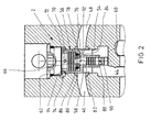
- FIG. 1 shows a section through a valve disc 1 of a control block of a mobile implement, such as a mini or compact excavator, backhoe loader, telescopic loader, skid steer loader.
- a proportionally adjustable directional control valve 4 and a LUDV pressure compensator 2 are added, via which the pressure fluid flow between a connected to working ports A, B consumers of the mobile implement and a pressure port and a tank port (both not shown) is controllable.
- the directional control valve 4 has a pressure medium volume flow to the consumer determining the speed part 6 and two direction parts 8, 10, via which the flow direction of the pressure medium is controlled to or from the consumer.
- the directional control valve 4 has a valve slide 12 which is biased by a centering spring 14 in the illustrated basic position.
- the actuation of the valve spool 12 via a laterally led out of the valve disc 1 operating portion 16 which is articulated to a lever or the like in the driver's cab.
- the valve spool 12 is guided in a valve bore 18, which in the radial direction to a pressure chamber 20, an inlet chamber 22, two approximately symmetrically to the pressure chamber 20 disposed drain chambers 24, 25, two on both sides thereof arranged working chambers 26, 28 and two adjacent thereto tank chambers 30, 32 is extended.
- the valve spool 12 has a central measuring diaphragm collar 34 which, together with the remaining annular web between the pressure chamber 20 and the inlet chamber 22, determines a measuring diaphragm forming the speed part 6.
- two control collars 36, 38 and two tank collars 40, 42 of the directional parts 8, 10 are arranged on the valve slide 12.
- the pressure chamber 20 is connected to the pressure port P and the two tank chambers 30, 32 are connected to the tank port T.
- the inlet chamber 22 is connected via a Inlet channel 44 connected to the input of the pressure compensator 2. Their output is connected via two drain channels 46, 48 with the drain chamber 24 and 25, respectively.
- the two working chambers 26, 28 are connected via working channels 50 and 52 to the working port A and B, respectively.
- the structure of the pressure compensator 2 will be explained with reference to the enlarged view in FIG. In Figures 1 and 2, the pressure compensator 2 is shown in the fully open operating position in which the inlet channel 44 is completely opened to the drainage channel 46 out.
- the pressure compensator 2 has a guided in a pressure compensator bore 54 pressure compensator piston 56, which is designed as a hollow stepped piston and is guided on a correspondingly stepped fixed inner part 58. This is determined in the axial direction by a shoulder 60 of the housing part and a screwed into the pressure balance bore 54 screw plug 62.
- the inner part 58 is pretensioned by means of a spring 64 in the direction of the shoulder 60.
- the inner part 58 further has a blind hole 66 which is closed to the shoulder 60 and which opens into a rear spring chamber 68 which is connected via radial bores 70 with a rear pressure chamber 72, in which the Druckwaagenkolbenendabrough larger diameter with its rear annular end face dips.
- This pressure chamber 72 is acted upon via an LS channel 74 with the greatest load pressure of all connected to the control block consumers.
- An inner ring end face 76 defines a damping space 80 with an annular end face 78 of the inner part in the axial direction, which is connected via a peripheral wall of the inner part 58 in the radial direction (perpendicular to the plane) passing through damping nozzle 82 with the blind hole 66.
- the damping chamber-side mouth region of the connecting recesses 84 is closed by an elastic O-ring 86, which acts as a check valve, which prevents a pressure medium flow from the damping chamber 80 through the connecting recesses 84 in the blind hole 66 and allows in the opposite direction.
- an annular groove 88 is formed, in which a Lastmeldeblende 90 opens, via which the entrance of the pressure compensator 2 is connected to the blind hole 66.
- This load indicator panel 90 is opened when the pressure compensator 2 is fully open, so that the pressure at the inlet of the pressure compensator, i. the individual load pressure also acts in the back pressure chamber 72 and is reported in the LS channel 74.
- the load indicator shutter 90 is closed in the embodiment shown in Figure 2.
- This pump pressure acts on the outer annular end face 92 of the pressure compensator piston 56 in the opening direction, while the rear-side annular end face 94 is acted upon by the pressure in the pressure chamber 72 and thus the load pressure.
- the pump control causes the pump pressure to increase until the load pressure, which keeps the pressure compensator closed, is reached.
- the pressure compensator piston 56 lifts from its stop on the shoulder 60 and opens the connection from the inlet channel 44 to the working channel 46.
- the control amount for the connected to the pump control LS-channel is taken by the consumer, which in unfavorable operating conditions of the connected consumer can fall.
- the pressure compensator 2 opens completely, so that the load indicator diaphragm 90 is opened and, correspondingly, the load pressure in the working channel 46 is guided into the pressure chamber 72 and thus into the LS channel 74.
- the damping chamber 80 is increased, so that accordingly pressure medium can flow from the blind bore 66 into the damping chamber 80.
- the elasticity of the O-ring 86 allows a pressure medium flow in this direction, so that pressure medium can flow through the comparatively large cross-section of the connecting recesses 84 - the closing movement of the damping piston is almost undamped, so that the load-higher consumer is driven virtually without delay.
- FIGS. 3 and 4 Two variants of a pressure compensator 2 are shown in FIGS. 3 and 4, wherein instead of the O-ring 86, other non-return valve arrangements are used.
- the basic structure of the pressure compensator 2 is in each case the same as in FIG. 2, so that only the differences are discussed below.
- the connecting recesses 84 are not formed in the radial direction between the damping chamber 80 and the blind hole 66, but they are designed as a trained symmetrically to the pressure compensator axis bore star.
- the check valve is formed by an annular closing disc 96, the the inner part 58 engages around and is inserted into an axial groove 98 on the lower end face of the larger end section of the inner part 58 in FIG.
- the closing disc 96 is biased in the closing direction by the force of a valve spring 100, which is supported on a spring plate 102 inserted into an annular groove of the inner part 58.
- the strength of the valve spring 100 is selected so that a pressure medium flow from the rear pressure chamber 72 into the damping chamber 80 during the closing movement of the pressure compensator piston 56 can be carried out with a relatively low pressure loss, so that the damping is substantially lower than during the closing movement of the pressure compensator piston, in the the pressure medium has to flow over the small damping nozzle 82.
- a single axial bore is provided in the inner part, into which a check valve 104 having a valve body 106 which is biased against a valve seat 108 is inserted.
- the function of this check valve 104 corresponds to that of the above-described embodiment, so that further explanations are unnecessary.
- FIG. 5 shows a further variant of a LUDV pressure compensator 2 according to the invention, in which, in addition to the one-sided damping described above, a load-holding function is integrated which prevents the load from sagging, so that additional load-holding valves can be dispensed with.
- a pressure balance piston 56 is guided axially displaceably on an inner part 58.
- the rear annular end face 94 is the pressure in the pressure chamber 72 and the outer annular end face 92 of the pressure at the entrance of the pressure compensator 2, i. from the pressure in the inlet channel 44 (downstream of the metering orifice) acted upon.
- the damping chamber 80 is formed, so that the inner ring end face 76 is acted upon by the pressure in this damping chamber 80 in the closing direction.
- the damping chamber side of an O-ring 86 are closed.
- the inner part 58 has a Lastmeldeblende 90.
- the embodiment of FIG 5 completely corresponds to the embodiment of Figure 2.
- the main difference is that the small damping nozzle 82 is not formed in the inner part but in the mantle of the damping piston 56, so that the damping chamber 80 is not connected via this damping nozzle 82 with the blind hole 66 but with the working channels 46, 48. That By means of the damping nozzle 82, the load pressure acting on the associated load acts in the damping chamber 80.
- a bore 110 is formed at the end portion of the pressure compensator piston 56 with a smaller diameter, which in the closed position of the pressure compensator 2 shown in FIG Lastmeldeblende 90 is aligned so that pressure medium from the inlet channel 44 can enter the blind hole 66.
- the damping chamber 80 further acts as a spring chamber for a spring 112, which is supported on the adjacent annular end face of the inner part 58 and engages the inner ring end face 76 of the pressure compensator piston 56. Also, this spring 112 serves to compensate for the design predetermined clearance in the axial direction and to ensure a rapid closing of the pressure compensator piston 56 - in principle, could be dispensed with the spring 112.
- the load pressure on the associated load via the working channels 46, 48 and the small damping nozzle 82 in the damping chamber 80 acts.
- the O-ring 86 blocks the passage to the blind hole 66 from.
- the pressure in the inlet channel 44 is effective via the load indicator cover 90 and the bore 110.
- this pressure corresponds to the inlet channel 44, i. the pressure downstream of the metering orifice initially substantially the pump pressure, so that in the pressure chamber 72 also applies pump pressure.
- the LS-channel 74 is thus filled via the pump in the illustrated basic position of the pressure balance and not - as in the above embodiments - on the load, so that a sagging of the consumer in the control due to a filling of the LS channel 74th is prevented.
- the pump control of the pump causes the applied pump pressure to rise until the load pressure which keeps the pressure compensator closed is reached. Since at the beginning of the control in the LS channel 74, the pump pressure acts and this is reported to the pump controller, this retracts, so to speak, "even high” until the balance of power is achieved with the effective force in the closing direction, which essentially by the on the inner ring end face 76 acting load pressure (and the pressure in the rear pressure chamber) is determined.
- the pressure compensator piston 56 then begins to open the passage to the working channel 46, 48 and thus to the consumer. At the same time, the overlap of the load indicator panel 90 with the bore 110 is released, so that the load indicator panel 90 is closed.
- FIG. 7 This operating state is shown in FIG. At first, a very low pressure medium volume flow flows to the consumer, ie the pressure drop across the metering orifice is low. The regulated by the pump control pressure drop is almost completely over the pressure compensator, which is further opened due to this pressure difference. The pressure compensator is finally completely opened (see FIG. 7), wherein the load alarm shutter 90 is opened again by the lower annular surface 114 of the pressure compensator piston 56. About the load indicator panel 90, the blind hole 66, the pressure chamber 72 and thus the LS channel 74 is supplied with a volume flow which is substantially constant by a downstream current regulator. The pressure drop, which generates this volume flow between the front and back of the pressure compensator 2, is greater than the force of the spring 112 - the pressure compensator remains fully open. The spring is - as I said - only to keep the pressure compensator in readiness to close.
- the pressure compensator piston 56 is moved quickly by the force acting on its inner ring end face 76 load pressure in its closed position and acts as a load-holding valve.
- FIG. 8 finally shows a variant of the exemplary embodiment described in FIGS. 5 to 7, in which no radial bore 110 is formed at the smaller diameter of the hollow pressure balance piston 56 but recesses 116 are formed in the end surface formed by the annular surface 114, which open into an annular gap 118. which is formed by a downgrading of the inner part 58.
- This annular gap 118 extends in the axial direction to the load indicator panel 90.
- a hydraulic control arrangement for load-independent control of a consumer with a continuously adjustable directional control valve and a downstream pressure compensator.
- the pressure compensator is damped on one side, so that the movement is damped in the opening direction and the movement in the closing direction is substantially unattenuated. It is further disclosed a control arrangement in which in the pressure compensator a load-holding function is integrated.
Landscapes
- Engineering & Computer Science (AREA)
- Physics & Mathematics (AREA)
- Fluid Mechanics (AREA)
- Mechanical Engineering (AREA)
- General Engineering & Computer Science (AREA)
- Fluid-Pressure Circuits (AREA)
- Safety Valves (AREA)
Abstract
Description
Die Erfindung betrifft eine hydraulische Steueranordnung zur lastunabhängigen Ansteuerung eines Verbrauchers gemäß dem Oberbegriff des Patentanspruches 1 und eine Druckwaage für eine derartige Steueranordnung.The invention relates to a hydraulic control arrangement for load-independent control of a consumer according to the preamble of
Der Grundaufbau derartiger Steueranordnungen ist beispielsweise aus der WO 95/32364 A1 bekannt. Bei einem derartigen LUDV-System ist jedem Verbraucher eine verstellbare Zumessblende mit nachgeschalteter Druckwaage zugeordnet, wobei letztere den Druckabfall über der Zumessblende konstant hält, so dass die zu dem entsprechenden hydraulischen Verbraucher fließende Druckmittelmenge vom Öffnungsquerschnitt der Zumessblende und nicht vom Lastdruck des Verbrauchers oder vom Pumpendruck abhängt. Da beispielsweise bei mobilen Arbeitsgeräten eine Vielzahl derartiger Ventilanordnungen parallel geschaltet sind, wird durch die Individualdruckwaagen des Systems erreicht, dass in dem Fall, in dem eine Hydropumpe des Systems bis zum maximalen Hubvolumen verstellt worden ist und der Druckmittelstrom nicht ausreicht, um den vorgegebenen Druckabfall über den Zumessblenden der jeweils einem Verbraucher zugeordneten Ventilanordnungen aufrecht zu erhalten, die Druckwaagen aller betätigten hydraulischen Verbraucher in Schließrichtung verstellt werden, so dass alle Druckmittelströme um den gleichen Prozentsatz verringert werden. Aufgrund dieser lastdruckunabhängigen Durchflussverteilung (LUDV) bewegen sich dann alle betätigten Verbraucher mit einer prozentual um den gleichen Wert verringerten Geschwindigkeit.The basic structure of such control arrangements is known, for example, from WO 95/32364 A1. In such a LUDV system, each consumer is assigned an adjustable metering orifice with a downstream pressure compensator, the latter keeping the pressure drop across the metering orifice constant, so that the quantity of fluid flowing to the corresponding hydraulic consumer depends on the opening cross section of the metering orifice and not on the load pressure of the consumer or on the pump pressure depends. Since, for example, in mobile implements a plurality of such valve assemblies are connected in parallel, is achieved by the individual pressure compensators of the system that in the case where a hydraulic pump of the system has been adjusted to the maximum displacement and the pressure medium flow is insufficient to the predetermined pressure drop across To maintain the metering orifices of each associated with a consumer valve assemblies, the pressure compensators of all actuated hydraulic consumers are adjusted in the closing direction, so that all pressure medium flows are reduced by the same percentage. Because of this load-pressure-independent flow distribution (LUDV), all actuated consumers then move at a speed that is reduced by the same amount.
Derartige LUDV-Hydrauliksysteme werden in immer größer werdenden Umfang bei mobilen Arbeitsgeräten mit kombinierten Bewegungen angewendet. Die Arbeitsbewegungen dieser mobilen Arbeitsgeräte (Mini- und Kompaktbagger, Baggerlader, Teleskoplader, Kompaktlader, etc.) sollen schwingungs- und druckfrei der Steuerung durch den Fahrer folgen. Es hat sich erwiesen, dass zur schwingungsfreien Steuerung eine Dämpfung der LUDV-Druckwaagen erforderlich ist.Such LUDV hydraulic systems are being used to an ever-increasing extent in mobile implements with combined movements. The working movements of these mobile working tools (mini and compact excavators, backhoe loaders, telescopic loaders, skid steer loaders, etc.) should follow the control of the driver without vibration and pressure. It has been proven that damping of the LUDV pressure compensators is required for vibration-free control.
Eine Dämpfung ist beispielsweise aus der US 6,532,989 B1 bekannt. Bei dieser bekannten Lösung hat die Druckwaage einen rückwärtigen Druckraum und einen ringförmigen Dämpfungsraum, die beide mit einem auf einen Druckwaagenkolben in Schließrichtung wirksamen Druck beaufschlagbar sind, während auf eine vordere Stirnfläche des Druckwaagenkolbens der stromabwärts der Messblende anliegende Druck, in der Regel der Lastdruck des angesteuerten Verbrauchers, in Öffnungsrichtung wirkt. Zwischen dem rückwärtigen Druckraum und dem Dämpfungsraum ist eine Dämpfungsdüse vorgesehen, durch die das Druckmittel bei der Axialverschiebung des Druckwaagenkolbens aus dem Dämpfungsraum heraus oder in diesen hineinströmen muss, so dass die Druckwaagenkolbenbewegung gedämpft ist. Eine derartige Dämpfung führt zwangsläufig zu Verzögerungen beim Öffnen und Schließen der Druckwaage mit der Folge eines verzögerten Bewegungsbeginns von Arbeitsbewegungen mit hoher Last.An attenuation is known, for example, from US Pat. No. 6,532,989 B1. In this known solution, the pressure compensator has a rear pressure chamber and an annular damping chamber, both of which can be acted upon by a pressure acting on a pressure compensator piston in the closing direction pressure, while on a front end face of the pressure compensator piston of the downstream of the metering orifice pressure applied, usually the load pressure of the driven Consumer, acts in the opening direction. Between the rear pressure chamber and the damping chamber, a damping nozzle is provided, through which the pressure medium must flow during the axial displacement of the pressure compensator piston out of the damping chamber or into this, so that the pressure compensator piston movement is damped. Such damping inevitably leads to delays in opening and closing the pressure compensator, resulting in a delayed start of movement of high-load work movements.
Demgegenüber liegt der Erfindung die Aufgabe zugrunde, eine Steueranordnung und eine dafür geeignete LUDV-Druckwaage zu schaffen, bei denen die Verzögerung der Arbeitsbewegung eines Verbrauchers trotz Dämpfung der Druckwaage minimiert ist.In contrast, the present invention seeks to provide a control arrangement and a suitable LUDV pressure compensator, in which the delay of the working movement of a consumer is minimized despite the damping of the pressure compensator.
Diese Aufgabe wird hinsichtlich der hydraulischen Steueranordnung durch die Merkmale des Patentanspruches 1 und hinsichtlich der Druckwaage durch die Merkmale des nebengeordneten Patentanspruches 12 gelöst.This object is achieved with regard to the hydraulic control arrangement by the features of
Erfindungsgemäß ist das zusätzlich zu der den Dämpfungsraum mit dem Druckraum verbindenden Dämpfungsdüse eine Verbindungsausnehmung mit größerem Querschnitt vorgesehen, über die der Dämpfungsraum mit einem rückwärtigen Druckraum verbunden ist, die durch ein in Richtung zum Dämpfungsraum hin öffnendes Rückschlagventil absperrbar ist. Durch diese Maßnahme ist die Bewegung des Druckwaagenkolbens in Öffnungsrichtung in Abhängigkeit vom Blendenquerschnitt relativ stark gedämpft, während in Schließrichtung das Rückschlagventil öffnet und somit einen vergleichsweise großen Querschnitt aufsteuert - d.h. die Druckwaage ist einseitig gedämpft, so dass die Druckwaage eines Verbrauchers mit niedrigem Lastdruck beispielsweise schnell schließt und auf diese Weise den den schnellen Druckaufbau auf einen höheren Lastdruck in einer anderen Scheibe ermöglicht.According to the invention, in addition to the damping chamber connecting the damping chamber with the pressure chamber, a connecting recess with a larger cross section is provided, via which the damping chamber is connected to a rear pressure chamber, which can be shut off by a non-return valve opening in the direction of the damping chamber. By this measure, the movement of the pressure compensator piston in the opening direction is relatively strongly damped in dependence on the diaphragm cross section, while in the closing direction opens the check valve and thus aufsteuert a comparatively large cross-section -. the pressure compensator is damped on one side, so that the pressure balance of a consumer with low load pressure, for example, quickly closes and in this way allows the rapid pressure build-up to a higher load pressure in another disc.
Bei einem bevorzugten Ausführungsbeispiel ist der Druckwaagenkolben als abgestufter Hohlkolben ausgeführt, wie es in der US 6,532,989 B1 beschrieben ist. Dieser Hohlkolben ist auf einem axialen Innenteil geführt, das mit einer Sacklochbohrung versehen ist, die in den rückwärtigen Druckraum mündet. Eine durch den abgestuften Teil des Druckwaagenkolbens gebildete Innenringstirnfläche begrenzt mit einem entsprechend ausgebildeten Abschnitt des Innenteils den Dämpfungsraum. Die fußseitige Ringstirnfläche des Stufenkolbens ist in Öffnungsrichtung der Druckwaage von dem Druck stromabwärts der Messblende beaufschlagt.In a preferred embodiment, the pressure balance piston is designed as a stepped hollow piston, as described in US 6,532,989 B1. This hollow piston is guided on an axial inner part, which is provided with a blind hole, which opens into the rear pressure chamber. A formed by the stepped portion of the pressure compensator piston inner ring end surface bounded with a correspondingly formed portion of the inner part of the damping chamber. The foot-side annular end face of the stepped piston is acted upon in the opening direction of the pressure compensator by the pressure downstream of the metering orifice.
Bei den bekannten Lösungen ist ein rückwärtiger Steuerraum der Druckwaagen mit der Lastmeldeleitung verbunden, in der der über eine Wechselventilkette abgegriffene höchste Lastdruck aller angesteuerten Verbraucher anliegt. Wenn nun der Lastdruck eines betätigten hydraulischen Verbrauchers schnell über den gerade herrschenden höchsten Lastdruck ansteigt, so erhöht sich sofort der Druck an der Vorderseite des Druckwaagenkolbens der zugehörigen Druckwaage, während ein entsprechender Druckanstieg im rückwärtigen Steuerraum über die Wechselventilkette und die Lastmeldeleitung verzögert stattfindet. Das dadurch bedingte kurzzeitige Kräfteungleichgewicht am Regelkolben der Druckwaage kann die Ansteuerung des hydraulischen Verbrauchers negativ beeinflussen. Beispielsweise kann der hydraulische Verbraucher kurz etwas absacken oder die lastunabhängige Durchflussverteilung gestört werden.In the known solutions, a rear control chamber of the pressure compensators is connected to the load reporting line, in which abuts the tapped via a shuttle valve chain highest load pressure of all driven consumers. Now, if the load pressure of an actuated hydraulic consumer quickly rises above the currently prevailing maximum load pressure, so immediately increases the pressure at the front of the pressure compensator piston of the associated pressure compensator, while a corresponding increase in pressure in the rear control chamber via the shuttle valve chain and the Lastmeldeleitung takes place delayed. The consequent short-term power imbalance on the control piston of the pressure compensator can adversely affect the control of the hydraulic load. For example, the hydraulic load can briefly sag slightly or the load-independent flow distribution can be disturbed.
Zur Vermeidung eines derartigen unerwünschten Absackens des Verbrauchers werden bei den vorgenannten Lösungen zusätzliche Lasthalteventile in den Druckmittelströmungspfad zwischen dem Verbraucher und der Druckwaage geschaltet, so dass das Abströmen des Druckmittels vom Verbraucher über die Druckwaage verhindert werden kann. Derartige zusätzliche Lasthalteventile verteuern jedoch die Steueranordnung und benötigen einen erheblichen Bauraum.To avoid such unwanted sagging of the consumer additional load holding valves are connected in the pressure medium flow path between the consumer and the pressure compensator in the aforementioned solutions, so that the outflow of the pressure medium can be prevented by the consumer via the pressure compensator. However, such additional load-holding valves make the control arrangement more expensive and require considerable space.
Zur Beseitigung dieses Nachteils werden in der US 5,067,389, der US 5,890,362 und der US 4,787,294 Druckwaagen vorgeschlagen, bei denen die Lasthaltung in die Funktion der Druckwaage integriert ist. Dabei wird die Druckwaage mit zwei hintereinander angeordneten Druckwaagenkolben versehen, die derart geschaltet sind, dass die Druckwaage geschlossen wird, wenn der am Eingang der Druckwaage anliegende Druck bei offenem Druckwaagenkolben niedriger als der individuelle Lastdruck ist.To overcome this disadvantage, pressure compensators are proposed in US Pat. No. 5,067,389, US Pat. No. 5,890,362 and US Pat. No. 4,787,294, in which the load position is integrated into the function of the pressure compensator. In this case, the pressure compensator is provided with two successively arranged pressure compensator pistons which are connected in such a way that the pressure compensator is closed when the pressure applied to the inlet of the pressure compensator is open Pressure compensator piston is lower than the individual load pressure.
In der DE 40 05 966 C2 wird eine Lösung vorgeschlagen, bei der in den Druckwaagenkolben ein Wechselventil integriert ist, über das der Druck stromabwärts der Zumessblende und im Lastmeldekanal verglichen und in den rückwärtigen Steuerraum gemeldet wird.In
In der DE 296 17 735 U1 ist eine Druckwaage beschrieben, bei der die Lastmeldung über eine aufwendige Wechselventilschaltung mit Rückschlagventilen und Düsen erfolgt, um die Druckwaage der Lasthaltefunktion im geschlossenen Zustand zu halten.In DE 296 17 735 U1 a pressure compensator is described, in which the load is reported on a complicated shuttle valve circuit with check valves and nozzles to keep the pressure balance of the load-holding function in the closed state.
All die vorbeschriebenen bekannten Lösungen mit einer Lasthaltefunktion in der Druckwaage haben den Nachteil gemeinsam, dass ein erheblicher Aufwand erforderlich ist, um einen Steuerdruck abzugreifen, der den Druckwaagenkolben in der Lasthaltefunktion in Schließrichtung beaufschlagt.All the above-described known solutions with a load-holding function in the pressure balance have the disadvantage that a considerable effort is required to tap a control pressure, which acts on the pressure compensator piston in the load holding function in the closing direction.
Gemäß einer - auch unabhängig von Patentanspruch 1 beanspruchbaren - Ausführungsform ist der Dämpfungsraum über die Dämpfungsdüse mit dem den individuellen Lastdruck führenden Kanal verbunden, so dass in dem Fall, in dem der Druck am Eingang der Druckwaage unter diesen Lastdruck absinkt, der Druckwaagenkolben über den im Dämpfungsraum anliegenden individuellen Lastdruck in seine Schließstellung gebracht wird, so dass die Druckwaage die Lasthaltefunktion mit übernimmt. Gegenüber den vorher beschriebenen Lösungen mit Lasthaltefunktion zeichnet sich die erfindungsgemäße Konstruktion durch eine äußerst kompakte und einfache Bauweise aus.According to an embodiment, which can also be claimed independently of
Alternativ kann die Dämpfungsdüse auch den Dämpfungsraum mit dem rückwärtigen Druckraum verbinden, wobei allerdings auf die Lasthaltefunktion verzichtet wird.Alternatively, the damping nozzle also connect the damping chamber with the rear pressure chamber, although the load-holding function is dispensed with.
Es wird bevorzugt, wenn an einem fußseitigen Endabschnitt des Innenteils eine im Sackloch mündende Querbohrung vorgesehen ist, die in der Öffnungsstellung des Druckwaagenkolbens vollständig aufgesteuert ist, so dass der Druck stromabwärts der Messblende abgegriffen und in den rückwärtigen Druckraum geführt wird.It is preferred if a transverse bore opening in the blind hole is provided at a foot-side end portion of the inner part, which is completely opened in the open position of the pressure compensator piston, so that the pressure is tapped downstream of the metering orifice and guided into the rear pressure chamber.
Bei einem besonders bevorzugten Ausführungsbeispiel ist am kleineren Durchmesser des Druckwaagenkolbens eine Bohrung oder eine Ausnehmung ausgebildet, die derart mit Bezug zur Querbohrung positioniert werden kann, dass der Druck stromabwärts der Messblende in die Sacklochbohrung gemeldet wird.In a particularly preferred embodiment, a bore or a recess is formed at the smaller diameter of the pressure compensator piston, which can be positioned with respect to the transverse bore, that the pressure downstream of the metering orifice is reported in the blind hole.
Bei einer erfindungsgemäßen Alternativlösung ist diese Verbindung zwischen dem Kanal stromabwärts der Messblende und dem rückwärtigen Druckraum immer geöffnet. Bei einer bevorzugten Lösung ist diese Verbindung jedoch nur während des Anfangshubs (von der Schließstellung gesehen) der Druckwaage und bei vollständig geöffneter Druckwaage aufgesteuert, während im dazwischen liegenden Bereich diese Verbindung geschlossen ist, so dass der rückwärtige Druckraum dann mit dem höchsten wirksamen Lastdruck beaufschlagt ist, während er zu Beginn des Aufsteuerns der Druckwaage mit dem Druck stromabwärts der Messblende - d.h. etwa dem Pumpendruck - beaufschlagt ist.In an alternative solution according to the invention, this connection between the channel downstream of the metering orifice and the rear pressure chamber is always open. In a preferred solution, however, this compound is opened only during the initial stroke (seen from the closed position) of the pressure compensator and fully open pressure compensator, while in the intermediate region of this connection is closed, so that the rear pressure chamber is then subjected to the highest effective load pressure while at the beginning of the up-steer of the pressure compensator with the pressure downstream of the orifice plate - ie about the pump pressure - is applied.
Das erfindungsgemäße Rückschlagventil kann durch einen einfachen O-Ring gebildet sein, der auf das Innenteil aufgesetzt ist oder durch eine in eine Schließstellung vorgespannte Schließscheibe. Alternativ können auch herkömmliche Rückschlagventile mit federvorgespannten Schließkörpern verwendet werden.The check valve according to the invention may be formed by a simple O-ring, which is placed on the inner part or by a in one Closed position pre-tensioned closing disc. Alternatively, conventional check valves can be used with spring-biased closing bodies.
Der Druckwaagenkolben kann durch eine vergleichsweise schwache Regelfeder in Schließstellung vorgespannt sein.The pressure compensator piston can be biased by a comparatively weak control spring in the closed position.
Sonstige vorteilhafte Weiterbildungen der Erfindung sind Gegenstand weiterer Unteransprüche.Other advantageous developments of the invention are the subject of further subclaims.
Im folgenden werden bevorzugte Ausführungsbeispiele der Erfindung anhand schematischer Zeichnungen näher erläutert. Es zeigen:
Figur 1 eine Schnittdarstellung einer Ventilscheibe mit einer halbseitig gedämpften LUDV-Druckwaage;Figur 2 eine vergrößerte Darstellung einer LUDV-Druckwaage gemäßFigur 1;- Figuren 3 und 4 Ausführungsbeispiele der halbseitig gedämpften Druckwaage aus
Figur 1; - Figur 5 eine LUDV-Druckwaage mit integrierter Lasthaltefunktion;
Figuren 6 und 7 Betriebszustände der LUDV-Druckwaage aus Figur 5 undFigur 8 ein weiteres Ausführungsbeispiel einer LUDV-Druckwaage mit Lasthaltefunktion.
- Figure 1 is a sectional view of a valve disc with a half-damped LUDV pressure compensator;
- Figure 2 is an enlarged view of a LUDV pressure compensator according to Figure 1;
- Figures 3 and 4 embodiments of the half-side damped pressure compensator of Figure 1;
- FIG. 5 shows a LUDV pressure balance with integrated load holding function;
- Figures 6 and 7 operating states of the LUDV pressure compensator of Figure 5 and
- Figure 8 shows another embodiment of a LUDV pressure compensator with load-holding function.
Figur 1 zeigt einen Schnitt durch eine Ventilscheibe 1 eines Steuerblockes eines mobilen Arbeitsgerätes, beispielsweise eines Mini- oder Kompaktbaggers, Baggerladers, Teleskopladers, Kompaktladers. In dieser Ventilscheibe 1 sind ein proportional verstellbares Wegeventil 4 und eine LUDV-Druckwaage 2 aufgenommen, über die die Druckmittelströmung zwischen einem an Arbeitsanschlüsse A, B angeschlossenen Verbraucher des mobilen Arbeitsgerätes und einem Druckanschluss und einem Tankanschluss (beide nicht dargestellt) steuerbar ist. Das Wegeventil 4 hat einen den Druckmittelvolumenstrom zum Verbraucher bestimmenden Geschwindigkeitsteil 6 und zwei Richtungsteile 8, 10, über die die Strömungsrichtung des Druckmittels zum bzw. vom Verbraucher gesteuert ist.Figure 1 shows a section through a
Das Wegeventil 4 hat einen Ventilschieber 12, der über eine Zentrierfederanordnung 14 in die dargestellte Grundposition vorgespannt ist. Die Betätigung des Ventilschiebers 12 erfolgt über einen seitlich aus der Ventilscheibe 1 herausgeführten Betätigungsabschnitt 16, der an einen Stellhebel oder dergleichen in der Fahrerkabine angelenkt ist.The
Der Ventilschieber 12 ist in einer Ventilbohrung 18 geführt, die in Radialrichtung zu einer Druckkammer 20, einer Zulaufkammer 22, zwei etwa symmetrisch zur Druckkammer 20 angeordneten Ablaufkammern 24, 25, zwei beidseitig davon angeordneten Arbeitskammern 26, 28 sowie zu zwei dazu benachbarten Tankkammern 30, 32 erweitert ist. Der Ventilschieber 12 hat einen mittigen Messblendenbund 34, der gemeinsam mit dem verbleibenden Ringsteg zwischen der Druckkammer 20 und der Zulaufkammer 22 eine den Geschwindigkeitsteil 6 ausbildende Messblende bestimmt. Beidseitig dieses Messblendenbundes 34 sind zwei Steuerbünde 36, 38 und zwei Tankbünde 40, 42 der Richtungssteile 8,10 am Ventilschieber 12 angeordnet.The
Die Druckkammer 20 ist an den Druckanschluss P und die beiden Tankkammern 30, 32 sind an den Tankanschluss T angeschlossen. Die Zulaufkammer 22 ist über einen Zulaufkanal 44 mit dem Eingang der Druckwaage 2 verbunden. Deren Ausgang ist über zwei Ablaufkanäle 46, 48 mit der Ablaufkammer 24 bzw. 25 verbunden. Die beiden Arbeitskammern 26, 28 sind über Arbeitskanäle 50 bzw. 52 mit dem Arbeitsanschluss A bzw. B verbunden.The
Der Aufbau der Druckwaage 2 wird anhand der vergrößerten Darstellung in Figur 2 erläutert. In den Figuren 1 und 2 ist die Druckwaage 2 in der vollständig geöffneten Betriebsposition dargestellt, in der der Zulaufkanal 44 vollständig zum Ablaufkanal 46 hin aufgesteuert ist. Die Druckwaage 2 hat einen in einer Druckwaagenbohrung 54 geführten Druckwaagenkolben 56, der als hohler Stufenkolben ausgeführt ist und auf einem entsprechend abgestuften feststehenden Innenteil 58 geführt ist. Dieses ist in Axialrichtung durch eine Schulter 60 des Gehäuseteiles und eine in die Druckwaagenbohrung 54 eingeschraubte Verschlussschraube 62 festgelegt. Wie insbesondere Figur 1 entnehmbar ist, wird zum Ausgleich eines konstruktiv erforderlichen Axialspiels das Innenteil 58 mittels einer Feder 64 in Richtung auf die Schulter 60 vorgespannt. Diese Feder 64 ist in der teilgeschnittenen Darstellung in Figur 2 nicht zu sehen. Das Innenteil 58 hat des weiteren eine Sacklochbohrung 66, die zur Schulter 60 hin verschlossen ist und die in einem rückwärtigen Federraum 68 mündet, der über Radialbohrungen 70 mit einem rückwärtigen Druckraum 72 verbunden ist, in den der Druckwaagenkolbenendabschnitt mit dem größeren Durchmesser mit seiner rückwärtigen Ringstirnfläche eintaucht. Dieser Druckraum 72 ist über einen LS-Kanal 74 mit dem größten Lastdruck aller an den Steuerblock angeschlossenen Verbraucher beaufschlagt.The structure of the
Eine Innenringstirnfläche 76 begrenzt mit einer Ringstirnfläche 78 des Innenteils einen Dämpfungsraum 80 in Axialrichtung, der über eine eine Umfangswandung des Innenteils 58 in Radialrichtung (senkrecht zur Zeichenebene) durchsetzende Dämpfungsdüse 82 mit der Sacklochbohrung 66 verbunden ist. Parallel zu dieser Dämpfungsdüse 82, die eine vergleichsweise kleinen Durchmesser hat, sind im Innenteil 58 noch mehrere radial verlaufende Verbindungsausnehmungen 84 ausgebildet, die sich ebenfalls zwischen der Sacklochbohrung 66 und dem Dämpfungsraum 80 erstrecken. Der dämpfungsraumseitige Mündungsbereich der Verbindungsausnehmungen 84 ist durch einen elastischen O-Ring 86 verschlossen, der als Rückschlagventil wirkt, das eine Druckmittelströmung vom Dämpfungsraum 80 durch die Verbindungsausnehmungen 84 in die Sacklochbohrung 66 unterbindet und in Gegenrichtung zulässt.An inner
Am fußseitigen Endabschnitt des Innenteils 58 ist eine Ringnut 88 ausgebildet, in der eine Lastmeldeblende 90 mündet, über die der Eingang der Druckwaage 2 mit der Sacklochbohrung 66 verbunden ist. Diese Lastmeldeblende 90 ist bei vollständig geöffneter Druckwaage 2 aufgesteuert, so dass der Druck am Eingang der Druckwaage, d.h. der individuelle Lastdruck auch im rückseitigen Druckraum 72 wirkt und in den LS-Kanal 74 gemeldet wird. In der Schließstellung des Druckwaagenkolbens 56 ist die Lastmeldeblende 90 bei dem in Figur 2 dargestellten Ausführungsbeispiel geschlossen.At the foot-side end portion of the
In der in Figur 1 dargestellten Grundposition des Ventilschiebers ist die Messblende zugesteuert und die beiden Arbeitsanschlüsse A, B gegenüber dem Tankkanal T abgesperrt. Die Druckwaage ist geschlossen und somit auch die Verbindung zwischen den Kanälen 46, 48 und 44 abgesperrt. Bei Axialverschiebung des Ventilschiebers 12 beispielsweise nach rechts in Figur 1, wird durch die am Messblendenbund 34 ausgebildeten Steuerkerben eine Messblendenöffnung geöffnet, über die die Druckkammer 20 mit der Zulaufkammer 22 verbunden ist. Zu Beginn dieser Aufsteuerbewegung entspricht der Druck in der Zulaufkammer 44 etwa dem Pumpendruck. Dieser Pumpendruck wirkt auf die äußere Ringstirnfläche 92 des Druckwaagenkolbens 56 in Öffnungsrichtung, während die rückseitige Ringstirnfläche 94 durch den Druck im Druckraum 72 und damit den Lastdruck beaufschlagt ist. Die Pumpenregelung lässt den Pumpendruck so lange ansteigen bis der Lastdruck, welcher die Druckwaage geschlossen hält, erreicht ist. Der Druckwaagenkolben 56 hebt von seinem Anschlag an der Schulter 60 ab und öffnet die Verbindung vom Zulaufkanal 44 zum Arbeitskanal 46. Bei dieser gezeigten Variante wird die Steuermenge für den mit der Pumpenregelung verbundenen LS-Kanal vom Verbraucher genommen, wodurch bei ungünstigen Betriebsbedingungen der angeschlossene Verbraucher absinken kann.In the illustrated in Figure 1 basic position of the valve spool the metering orifice is closed and shut off the two working ports A, B with respect to the tank channel T. The pressure balance is closed and thus the connection between the
In dem Fall, in dem nur der eine Verbraucher angesteuert wird, öffnet die Druckwaage 2 vollständig, so dass die Lastmeldeblende 90 geöffnet und entsprechend der Lastdruck im Arbeitskanal 46 in den Druckraum 72 und damit in den LS-Kanal 74 geführt wird.In the case in which only one consumer is controlled, the
Während Öffnungsbewegungen des Druckwaagenkolbens 56 muss Druckmittel aus dem sich verkleinernden Dämpfungsraum 80 verdrängt werden. Da der vergleichsweise große Querschnitt der Verbindungsausnehmungen 84 durch den O-Ring 86 abgesperrt sind, strömt das Druckmittel durch die kleine Dämpfungsdüse 82 in die sacklochbohrung 66, so dass die Öffnungsbewegung des Druckwaagenkolbens 56 relativ stark gedämpft ist.During opening movements of the
Wird ein zweiter Verbraucher mit höherem Lastdruck betätigt, so wirkt dieser höhere Lastdruck in dem allen Verbrauchern gemeinsamen LS-Kanal 74 - der Druckwaagenkolben 56 wird entsprechend in Schließrichtung bewegt bis ein Druckgleichgewicht hergestellt ist. In dieser Regelposition wird der Druckabfall über der zugeordneten Messblende konstant gehalten, wodurch auch die an jeden Verbraucher gewählte Durchflussmenge verhältnisgleich konstant gehalten ist.If a second consumer is actuated with a higher load pressure, then this higher load pressure acts in all Consumers common LS channel 74 - the
Während dieser Schließbewegung des Druckwaagenkolbens 56 wird der Dämpfungsraum 80 vergrößert, so dass entsprechend Druckmittel aus der Sacklochbohrung 66 in den Dämpfungsraum 80 nachströmen kann. Die Elastizität des O-Rings 86 lässt eine Druckmittelströmung in dieser Richtung zu, so dass Druckmittel durch den vergleichsweise großen Querschnitt der Verbindungsausnehmungen 84 strömen kann - die Schließbewegung des Dämpfungskolbens erfolgt nahezu ungedämpft, so dass der lasthöhere Verbraucher praktisch ohne Verzögerung angesteuert wird.During this closing movement of the
In den Figuren 3 und 4 sind zwei Varianten einer Druckwaage 2 dargestellt, wobei anstelle des O-Rings 86 andere Rückschlagventilanordnungen verwendet werden.Two variants of a
Der Grundaufbau der Druckwaage 2 ist jeweils der gleiche wie in Figur 2, so dass im folgenden lediglich auf die Unterschiede eingegangen wird. Bei dem in Figur 3 dargestellten Ausführungsbeispiel sind die Verbindungsausnehmungen 84 nicht in Radialrichtung zwischen dem Dämpfungsraum 80 und der Sacklochbohrung 66 ausgebildet, sondern sie sind als ein symmetrisch zur Druckwaagenachse ausgebildeter Bohrungsstern ausgebildet. Über diese axial verlaufenden Verbindungsausnehmungen 84 wird der rückwärtige Druckraum 72 direkt mit dem Dämpfungsraum 80 verbunden. Das Rückschlagventil ist durch eine ringförmige Schließscheibe 96 gebildet, die das Innenteil 58 umgreift und in eine Axialnut 98 an der in Figur 3 unteren Stirnfläche des größeren Endabschnittes des Innenteils 58 eingesetzt ist. Die Schließscheibe 96 wird in Schließrichtung durch die Kraft einer Ventilfeder 100 vorgespannt, die an einem in eine Ringnut des Innenteils 58 eingesetzten Federteller 102 abgestützt ist. Die Stärke der Ventilfeder 100 ist so ausgewählt, dass eine Druckmittelströmung vom rückwärtigen Druckraum 72 in den Dämpfungsraum 80 bei der Schließbewegung des Druckwaagenkolbens 56 mit einem vergleichsweise geringen Druckverlust erfolgen kann, so dass die Dämpfung wesentlich geringer als während der Schließbewegung des Druckwaagenkolbens ist, bei der das Druckmittel über die kleine Dämpfungsdüse 82 strömen muss.The basic structure of the
Bei dem in Figur 4 dargestellten Ausführungsbeispiel wird anstelle des von der Ventilscheibe 96 verschließbaren Bohrungsstern eine einzige Axialbohrung im Innenteil vorgesehen, in die ein Rückschlagventil 104 mit einem Ventilkörper 106 eingesetzt ist, der gegen eine Ventilsitz 108 vorgespannt ist. Die Funktion dieses Rückschlagventils 104 entspricht derjenigen des vorbeschriebenen Ausführungsbeispiels, so dass weitere Erläuterungen entbehrlich sind.In the embodiment shown in FIG. 4, instead of the bore star which can be closed by the
Figur 5 zeigt eine weitere Variante einer erfindungsgemäßen LUDV-Druckwaage 2, bei der neben der vorbeschriebenen einseitigen Dämpfung noch eine Lasthaltefunktion integriert ist, die ein Absacken der Last verhindert, so dass auf zusätzliche Lasthalteventile verzichtet werden kann.FIG. 5 shows a further variant of a
Der Grundaufbau des in Figur 5 dargestellten Ausführungsbeispiels entspricht weitestgehend demjenigen der vorbeschriebenen Ausführungsbeispiele, so dass nur auf die Unterschiede eingegangen wird.The basic structure of the embodiment shown in Figure 5 largely corresponds to that the above-described embodiments, so that only the differences will be discussed.
Auch bei der Variante gemäß Figur 5 ist ein Druckwaagenkolben 56 axial verschiebbar auf einem Innenteil 58 geführt. Die rückseitige Ringstirnfläche 94 ist vom Druck im Druckraum 72 und die äußere Ringstirnfläche 92 vom Druck am Eingang der Druckwaage 2, d.h. vom Druck im Zulaufkanal 44 (stromabwärts der Messblende) beaufschlagt. Im Inneren des Druckwaagenkolbens 56 ist wiederum der Dämpfungsraum 80 ausgebildet, so dass die Innenringstirnfläche 76 vom Druck in diesem Dämpfungsraum 80 in Schließrichtung beaufschlagt wird. Zwischen der Sacklochbohrung 66 des Innenteils 58 und dem Dämpfungsraum 80 sind - wie beim Ausführungsbeispiel gemäß Figur 2 - radial verlaufende Verbindungsausnehmungen 84 ausgebildet, die dämpfungsraumseitig von einem O-Ring 86 verschlossen sind. Am fußseitigen Endabschnitt hat das Innenteil 58 eine Lastmeldeblende 90. Bis hierhin entspricht das Ausführungsbeispiel gemäß Figur 5 vollständig dem Ausführungsbeispiel gemäß Figur 2. Der wesentliche Unterschied besteht darin, dass die kleine Dämpfungsdüse 82 nicht im Innenteil sondern im Mantel des Dämpfungskolbens 56 ausgebildet ist, so dass der Dämpfungsraum 80 über diese Dämpfungsdüse 82 nicht mit der Sacklochbohrung 66 sondern mit den Arbeitskanälen 46, 48 verbunden ist. D.h. über die Dämpfungsdüse 82 wirkt der am zugeordneten Verbraucher wirksame Lastdruck im Dämpfungsraum 80.Also in the variant according to FIG. 5, a
Des weiteren ist an dem Endabschnitt des Druckwaagenkolbens 56 mit kleinerem Durchmesser eine Bohrung 110 ausgebildet, die in der in Figur 5 dargestellten Schließstellung der Druckwaage 2 mit der Lastmeldeblende 90 fluchtet, so dass Druckmittel vom Zulaufkanal 44 in die Sacklochbohrung 66 eintreten kann.Furthermore, a
Der Dämpfungsraum 80 wirkt des weiteren noch als Federraum für eine Feder 112, die an der benachbarten Ringstirnfläche des Innenteils 58 abgestützt ist und an der Innenringstirnfläche 76 des Druckwaagenkolbens 56 angreift. Auch diese Feder 112 dient dazu, das konstruktiv vorgegebene Spiel in Axialrichtung auszugleichen und ein schnelles Schließen des Druckwaagenkolbens 56 zu gewährleisten - prinzipiell könnte auf die Feder 112 verzichtet werden.The damping
In der Grundposition des Steuerschiebers und bei geschlossener Druckwaage 2 wirkt der Lastdruck am zugeordneten Verbraucher über die Arbeitskanäle 46, 48 und die kleine Dämpfungsdüse 82 im Dämpfungsraum 80. Der O-Ring 86 sperrt den Durchgang zur Sacklochbohrung 66 ab. In der Sacklochbohrung 66 und im damit verbundenen Druckraum ist über die Lastmeldeblende 90 und die Bohrung 110 der Druck im Zulaufkanal 44 wirksam.In the basic position of the spool valve and
Bei Betätigung des Ventilschiebers 12 entspricht dieser Druck im Zulaufkanal 44, d.h. der Druck stromabwärts der Messblende zunächst im wesentlichen dem Pumpendruck, so dass im Druckraum 72 ebenfalls Pumpendruck anliegt. Bei diesem Ausführungsbeispiel wird somit in der dargestellten Grundposition der Druckwaage der LS-Kanal 74 über die Pumpe gefüllt und nicht - wie bei den vorbeschriebenen Ausführungsbeispielen - über die Last, so dass ein Absacken des Verbrauchers bei der Ansteuerung aufgrund eines Füllens des LS-Kanals 74 verhindert wird.Upon actuation of the
Die Pumpenregelung der nicht dargestellten Pumpe lässt den anliegenden Pumpendruck so lange ansteigen bis der Lastdruck, welcher die Druckwaage geschlossen hält, erreicht ist. Da zu Beginn der Ansteuerung im LS-Kanal 74 der Pumpendruck wirkt und dieser an den Pumpenregler weiter gemeldet wird, zieht sich dieser sozusagen "selbst hoch" bis das Kräftegleichgewicht mit der in Schließrichtung wirksamen Kraft erreicht ist, die im wesentlichen durch den auf die Innenringstirnfläche 76 wirkenden Lastdruck (und den Druck im rückwärtigen Druckraum) bestimmt ist. Der Druckwaagenkolben 56 beginnt dann den Durchgang zum Arbeitskanal 46, 48 und damit zum Verbraucher zu öffnen. Gleichzeitig wird die Überdeckung der Lastmeldeblende 90 mit der Bohrung 110 aufgehoben, so dass die Lastmeldeblende 90 zugesteuert wird.The pump control of the pump, not shown, causes the applied pump pressure to rise until the load pressure which keeps the pressure compensator closed is reached. Since at the beginning of the control in the
Dieser Betriebszustand ist in Figur 6 dargestellt. Dabei fließt zunächst noch ein sehr geringer Druckmittelvolumenstrom zum Verbraucher, d.h. der Druckabfall über der Messblende ist gering. Der von der Pumpenregelung geregelte Druckabfall entsteht noch fast vollständig über der Druckwaage, welche aufgrund dieser Druckdifferenz weiter geöffnet wird. Die Druckwaage wird schließlich vollständig aufgesteuert (siehe Figur 7), wobei durch die untere Ringfläche 114 des Druckwaagenkolbens 56 die Lastmeldeblende 90 wieder aufgesteuert ist. Über die Lastmeldeblende 90 wird nun die Sacklochbohrung 66, der Druckraum 72 und damit der LS-Kanal 74 mit einem Volumenstrom versorgt, der durch einen nachgeschalteten Stromregler im wesentlichen konstant ist. Der Druckabfall, den dieser Volumenstrom zwischen der Vorder- und Rückseite der Druckwaage 2 erzeugt, ist größer als die Kraft der Feder 112 - die Druckwaage bleibt vollständig geöffnet. Die Feder dient - wie gesagt- nur dazu, die Druckwaage in Schließbereitschaft zu halten.This operating state is shown in FIG. At first, a very low pressure medium volume flow flows to the consumer, ie the pressure drop across the metering orifice is low. The regulated by the pump control pressure drop is almost completely over the pressure compensator, which is further opened due to this pressure difference. The pressure compensator is finally completely opened (see FIG. 7), wherein the
Wird nun ein weiterer Verbraucher mit höherem Lastdruck betätigt, so wird die Druckwaage des zuerst angesteuerten Verbrauchers in der vorbeschriebenen Weise in seine Regelposition gebracht, so dass der Druckabfall über der Messblende konstant bleibt und alle Verbraucher lastunabhängig mit Druckmittel versorgt werden.Now, if another consumer is operated with a higher load pressure, the pressure balance of the first driven consumer is brought in the manner described above in its control position, so that the pressure drop across the metering orifice remains constant and all consumers are supplied load-independent with pressure medium.
Fällt der Pumpendruck aufgrund Schwankungen in der Druckmittelversorgung unter den Lastdruck ab, so wird der Druckwaagenkolben 56 durch den auf seine Innenringstirnfläche 76 wirkenden Lastdruck schnell in seine Schließposition verfahren und wirkt als Lasthalteventil.If the pump pressure drops due to fluctuations in the pressure medium supply under the load pressure, the
Figur 8 zeigt schließlich eine Variante des in den Figuren 5 bis 7 beschriebenen Ausführungsbeispiels, bei dem am kleineren Durchmesser des hohlen Druckwaagenkolbens 56 keine radiale Bohrung 110 sondern in der von der Ringfläche 114 gebildeten Stirnfläche Ausnehmungen 116 ausgebildet sind, die in einem Ringspalt 118 münden, der durch eine Zurückstufung des Innenteils 58 gebildet ist. Dieser Ringspalt 118 erstreckt sich in Axialrichtung bis zur Lastmeldeblende 90. Bei vollständig geöffneter Druckwaage (links in Figur 8) ist die Lastmeldeblende 90 vollständig aufgesteuert, so dass kein hydraulischer Widerstand (Ringspalt 118) vorgeschaltet ist.FIG. 8 finally shows a variant of the exemplary embodiment described in FIGS. 5 to 7, in which no radial bore 110 is formed at the smaller diameter of the hollow
Bei dieser Variante wird somit die Lastmeldeleitung des Steuerblocks über sämtliche Scheiben mit Druckmittel versorgt, das von der Pumpe abgegriffen wird. Vorversuche zeigten, dass diese Variante die LUDV Steuerungscharakteristik beeinflußt, da die LS-Leitung von allen aktiven Verbrauchern versorgt wird.In this variant, thus the load-sensing line of the control block is supplied via all disks with pressure medium, which is tapped by the pump. Preliminary tests showed that this variant influences the LUDV control characteristics, since the LS line is supplied by all active consumers.
Die Anmelderin behält sich vor, auf die Lasthaltefunktion eine eigene Patentanmeldung zu richten, wobei der Anspruch auf das Beaufschlagen des Dämpfungsraums 80 mit dem Lastdruck gerichtet sein kann.The applicant reserves the right to focus on the load holding function of a separate patent application, the claim may be directed to the application of the damping
Offenbart ist eine hydraulische Steueranordnung zur lastunabhängigen Ansteuerung eines Verbrauchers mit einem stetig verstellbaren Wegeventil und einer nachgeschalteten Druckwaage. Erfindungsgemäß ist die Druckwaage einseitig gedämpft, so dass die Bewegung in Öffnungsrichtung gedämpft und die Bewegung in Schließrichtung im wesentlichen ungedämpft erfolgt. Es ist des weiteren eine Steueranordnung offenbart, bei der in die Druckwaage eine Lasthaltefunktion integriert ist.Disclosed is a hydraulic control arrangement for load-independent control of a consumer with a continuously adjustable directional control valve and a downstream pressure compensator. According to the invention, the pressure compensator is damped on one side, so that the movement is damped in the opening direction and the movement in the closing direction is substantially unattenuated. It is further disclosed a control arrangement in which in the pressure compensator a load-holding function is integrated.
- 11
- Ventilscheibevalve disc
- 22
- LUDV-DruckwaageLUDV pressure
- 44
- Wegeventilway valve
- 66
- Geschwindigkeitsteilspeed part
- 88th
- Richtungsteildirection part
- 1010
- Richtungsteildirection part
- 1212
- Ventilschiebervalve slide
- 1414
- Zentrierfederanordnungcentering
- 1616
- Betätigungsabschnittactuating section
- 1818
- Ventilbohrungvalve bore
- 2020
- Druckkammerpressure chamber
- 2222
- Zulaufkammerinlet chamber
- 2424
- Ablaufkammerdrain chamber
- 2525
- Ablaufkammerdrain chamber
- 2626
- Arbeitskammerworking chamber
- 2828
- Arbeitskammerworking chamber
- 3030
- Tankkammertank chamber
- 3232
- Tankkammertank chamber
- 3434
- MessblendenbundMeasuring orifice collar
- 3636
- Steuerbundcontrol collar
- 3838
- Steuerbundcontrol collar
- 4040
- Tankbundtank Bund
- 4242
- Tankbundtank Bund
- 4444
- Zulaufkanalinlet channel
- 4646
- Ablaufkanaldrain channel
- 4848
- Ablaufkanaldrain channel
- 5050
- Arbeitskanalworking channel
- 5252
- Arbeitskanalworking channel
- 5454
- DruckwaagenbohrungPressure compensator bore
- 5656
- DruckwaagenkolbenPressure regulator piston
- 5858
- Innenteilinner part
- 6060
- Schultershoulder
- 6262
- VerschlussschraubeScrew
- 6464
- Federfeather
- 6666
- SacklochbohrungBlind hole
- 6868
- Federraumspring chamber
- 7070
- Radialbohrungradial bore
- 7272
- Druckraumpressure chamber
- 7474
- LS-KanalLS-channel
- 7676
- InnenringstirnflächeInner annular face
- 7878
- RingstirnflächeAnnular face
- 8080
- Dämpfungsraumdamping space
- 8282
- Dämpfungsdüsedamping
- 8484
- Verbindungsausnehmungconnecting recess
- 8686
- O-RingO-ring
- 8888
- Ringnutring groove
- 9090
- LastmeldeblendeLoad-detecting orifice
- 9292
- äußere Ringstirnflächeouter ring end face
- 9494
- rückseitige Ringstirnflächerear ring end face
- 9696
- Schließscheibeclosing disk
- 9898
- Axialnutaxial groove
- 100100
- Ventilfedervalve spring
- 102102
- Federtellerspring plate
- 104104
- Rückschlagventilcheck valve
- 106106
- Ventilkörpervalve body
- 108108
- Ventilsitzvalve seat
- 110110
- Bohrungdrilling
- 112112
- Federfeather
- 114114
- Ringflächering surface
- 116116
- Ausnehmungenrecesses
- 118118
- Ringspaltannular gap
Claims (15)
- A hydraulic control arrangement for the load-independent control of a consumer, comprising a continuously adjustable distribution valve (4) which forms a metering orifice having a pressure compensator (2) down the line the pressure compensator piston (56) of which is a step piston so that the pressure compensator (2) includes a rear pressure chamber (72) and an annular damping chamber (80) which is connected via a damping nozzle (82) to an adjacent chamber (66, 46; 48) guiding pressure medium, wherein a control pressure acting on the pressure compensator piston (56) in the closing direction can be applied to the pressure chamber (72) and to the damping chamber (80), and wherein a pressure downstream of the metering orifice in the opening direction is applied to an outer annular face (92) of the pressure compensator piston (56), characterized by a connecting recess (84) between the rear pressure chamber (72) and the damping chamber (80), to which a check valve (86, 986, 104) opening toward the damping chamber (80) is allocated.
- A control arrangement according to claim 1, wherein the pressure compensator piston (56) is a hollow piston and is guided on an axial male member (58) having a blind hole bore (66) which opens into the rear pressure chamber (72).
- A control arrangement according to claim 2, wherein the damping nozzle (82) connects the damping chamber (80) to a passage (46, 48) guiding the load pressure of the corresponding consumer.
- A control arrangement according to claim 2, wherein the damping nozzle (82) connects the damping chamber (80) to the rear pressure chamber (72).
- A control arrangement according to any one of the claims 2 to 4, wherein at a bottom-side end portion of the male member (58) a load-detecting orifice (90) opening into the blind hole bore (66) is provided which is controlled to be completely opened in the opening position of the pressure compensator piston (56).
- A control arrangement according to claim 5, wherein at the smaller diameter of the pressure compensator piston (56) a bore (110) or a circumferential recess (116) is formed via which the pressure downstream of the metering orifice can be signaled into the blind hole bore (66).
- A control arrangement according to claim 6, wherein in the closing position of the pressure compensator piston (56) the bore (110) is in overlapping with the load-detecting orifice (90) which can be controlled to be closed in the subsequent stroke of the pressure compensator piston (56) and can be controlled to be opened again by the pressure compensator piston (56) upon reaching the opening position.
- A control arrangement according to claim 7, wherein the circumferential recess (116) opens into an annular gap (118) between the male member (58) and the pressure compensator piston (56) extending toward the load-detecting orifice (90).
- A control arrangement according to any one of the preceding claims, wherein the connecting recess (84) is formed by a bore star opening into the blind hole bore (66) and being closable by an O-ring (86) placed on the male member (58).
- A control arrangement according to any one of the claims 1 to 8, wherein the connecting recess (84) is formed by a bore of the male member (58) opening into the pressure chamber (80) in which bore a check valve (104) is accommodated.
- A control arrangement according to any one of the claims 1 to 9, wherein the pressure compensator piston (56) is biased into its closing position by a spring.
- A pressure compensator for a hydraulic control arrangement according to any one of the preceding claims, comprising a stepped pressure compensator piston (56) in the form of a hollow piston and guided on a male member (58), whose rear annular face (94) delimits a rear pressure chamber (72) and whose inner annular face (76) delimits an annular damping chamber (80) in sections, said damping chamber being connected to an adjacent chamber guiding pressure medium via a damping nozzle (82), wherein a pressure acting in the closing direction can be applied to the inner annular face (76) and the rear annular face (94) and a pressure acting in the opening direction can be applied to an outer annular face (92), characterized by a connecting recess (84) of the male member (58) between the rear pressure chamber (72) and the damping chamber (80), a check valve (86, 96, 104) opening toward the damping chamber (80) being allocated to said connecting recess.
- A pressure compensator according to claim 12, wherein the damping nozzle (82) connects the damping chamber (80) to a pressure chamber guiding the load pressure of a corresponding consumer.
- A pressure compensator according to claim 12, wherein the damping nozzle (82) connects the damping chamber (80) to the rear pressure chamber (72).
- A pressure compensator according to any one of the claims 12 to 14, wherein in the male member a blind hole bore (66) opening into the rear pressure chamber (72) is formed into which a load-detecting orifice (90) opens at the bottom side, a bore (110) of the pressure compensator piston (56) being allocated to the load-detecting orifice (90) and being overlapped with the load-detecting orifice (90) in the closing position of the pressure compensator piston (56), wherein upon a subsequent opening movement the load-detecting orifice (90) can be controlled to be closed and in the completely opened position of the pressure compensator piston (56) can be controlled to be opened again.
Applications Claiming Priority (2)
| Application Number | Priority Date | Filing Date | Title |
|---|---|---|---|
| DE2003125296 DE10325296A1 (en) | 2003-06-04 | 2003-06-04 | Hydraulic control arrangement |
| PCT/EP2004/005837 WO2004109125A1 (en) | 2003-06-04 | 2004-05-28 | Hydraulic control arrangement |
Publications (2)
| Publication Number | Publication Date |
|---|---|
| EP1629209A1 EP1629209A1 (en) | 2006-03-01 |
| EP1629209B1 true EP1629209B1 (en) | 2007-01-03 |
Family
ID=33482510
Family Applications (1)
| Application Number | Title | Priority Date | Filing Date |
|---|---|---|---|
| EP04735220A Not-in-force EP1629209B1 (en) | 2003-06-04 | 2004-05-28 | Hydraulic control arrangement |
Country Status (6)
| Country | Link |
|---|---|
| US (1) | US7628174B2 (en) |
| EP (1) | EP1629209B1 (en) |
| JP (1) | JP4851318B2 (en) |
| AT (1) | ATE350586T1 (en) |
| DE (2) | DE10325296A1 (en) |
| WO (1) | WO2004109125A1 (en) |
Families Citing this family (8)
| Publication number | Priority date | Publication date | Assignee | Title |
|---|---|---|---|---|
| JP4276491B2 (en) * | 2003-08-04 | 2009-06-10 | 日立建機株式会社 | Directional valve block |
| US8646338B2 (en) * | 2010-02-02 | 2014-02-11 | Bucher Hydraulics S.P.A. | Hydraulic section for load sensing applications and multiple hydraulic distributor |
| KR101852529B1 (en) | 2010-03-17 | 2018-04-27 | 파커-한니핀 코포레이션 | Hydraulic valve with pressure limiter |
| JP5602074B2 (en) * | 2011-03-16 | 2014-10-08 | カヤバ工業株式会社 | Control valve |
| GB2494902B (en) * | 2011-09-23 | 2019-03-13 | Parker Hannifin Mfg Uk Limited | A valve with integrated pressure compensator |
| DE102012218427A1 (en) * | 2012-10-10 | 2014-04-10 | Robert Bosch Gmbh | Hydraulic control arrangement for use in hydraulic drive of mini excavator, has outlet flow path formed from first working port to pressure medium sink and located above control throttle, and pressure unit placed above hydro pump |
| EP2918853B1 (en) | 2014-03-11 | 2016-03-09 | Bucher Hydraulics S.p.A. | Hydraulic section for load sensing applications and multiple hydraulic distributor |
| EP2980416B1 (en) * | 2014-07-31 | 2019-06-05 | Bucher Hydraulics S.p.A. | Hydraulic section for load sensing applications and multiple hydraulic distributor |
Family Cites Families (46)
| Publication number | Priority date | Publication date | Assignee | Title |
|---|---|---|---|---|
| US1366151A (en) * | 1919-11-11 | 1921-01-18 | Fort Wayne Engineering And Mfg | Check-valve |
| US2512189A (en) * | 1944-01-24 | 1950-06-20 | Waterman William | Protection of hydraulic systems |
| US2574314A (en) * | 1948-02-26 | 1951-11-06 | Bard Parker Company Inc | Timing device |
| US2671466A (en) * | 1950-09-26 | 1954-03-09 | Baker Oil Tools Inc | Check valve |
| NL292191A (en) * | 1962-04-30 | 1900-01-01 | ||
| US3194265A (en) * | 1962-05-02 | 1965-07-13 | Hydraulic Unit Specialities Co | Hydraulic control valve with void control means |
| US3182729A (en) * | 1962-12-05 | 1965-05-11 | Allis Chalmers Mfg Co | Hydraulic implement control for tractors |
| US3298394A (en) * | 1963-03-29 | 1967-01-17 | William J Chorkey | Check valve |
| US3263574A (en) * | 1964-06-15 | 1966-08-02 | Hydraulic Unit Specialities Co | Speed and directional control valve for double acting lift cylinder |
| US3534774A (en) * | 1968-11-14 | 1970-10-20 | Koehring Co | Pressure compensated control valve |
| GB1301462A (en) * | 1969-01-13 | 1972-12-29 | ||
| US3618690A (en) * | 1969-05-20 | 1971-11-09 | Caterpillar Tractor Co | Damping and air-purging means for relief valve |
| US3563137A (en) * | 1969-06-30 | 1971-02-16 | Cessna Aircraft Co | Hydraulic self-leveling control for boom and bucket |
| GB1422938A (en) * | 1972-01-14 | 1976-01-28 | Sperry Rand Ltd | Hydraulic valves |
| US4139021A (en) * | 1972-07-19 | 1979-02-13 | Cross Manufacturing, Inc. | Hydraulic control instrumentality |
| US3815477A (en) * | 1973-02-06 | 1974-06-11 | Cross Mfg Inc | Control valve instrumentality |
| US3970108A (en) * | 1973-10-23 | 1976-07-20 | Cross Manufacturing, Inc. | Priority hydraulic control valve |
| US4009864A (en) * | 1975-02-04 | 1977-03-01 | Caterpillar Tractor Co. | Throttling slot configuration for a valve spool |
| GB1513761A (en) * | 1975-02-19 | 1978-06-07 | Kontak Mfg Co Ltd | Detents for locking movable elements |
| GB1510418A (en) * | 1976-03-08 | 1978-05-10 | Caterpillar Tractor Co | Fluid control valve |
| US4256142A (en) * | 1979-08-20 | 1981-03-17 | Hancock Leonard H | Hydraulic control |
| US4766929A (en) * | 1986-03-24 | 1988-08-30 | Durabla Manufacturing Co. | Check valve |
| US4787294A (en) * | 1987-07-29 | 1988-11-29 | Hydreco, Incorporated | Sectional flow control and load check assembly |
| JPH0786361B2 (en) * | 1988-11-10 | 1995-09-20 | 株式会社ゼクセル | Hydraulic control valve |
| JPH0716943Y2 (en) * | 1989-01-27 | 1995-04-19 | 東芝機械株式会社 | Directional control valve |
| JPH07103882B2 (en) * | 1989-03-22 | 1995-11-08 | 株式会社小松製作所 | Hydraulic valve with pressure compensation |
| DE3911204A1 (en) * | 1989-04-06 | 1990-10-11 | Heilmeier & Weinlein | Directional control valve |
| KR920701694A (en) * | 1989-06-26 | 1992-08-12 | 가타다 데츄야 | Hydraulic hydraulic circuit device of working cylinder |
| DE4005967C2 (en) * | 1990-02-26 | 1996-05-09 | Rexroth Mannesmann Gmbh | Control arrangement for several hydraulic consumers |
| DE4005966C2 (en) * | 1990-02-26 | 1999-08-26 | Mannesmann Rexroth Ag | Valve arrangement for controlling two hydraulic consumers that can be operated simultaneously |
| US5067389A (en) * | 1990-08-30 | 1991-11-26 | Caterpillar Inc. | Load check and pressure compensating valve |
| JP2744846B2 (en) * | 1990-11-26 | 1998-04-28 | 日立建機株式会社 | Hydraulic drive and directional switching valve |
| FR2689575B1 (en) * | 1992-04-06 | 1994-07-08 | Rexroth Sigma | HYDRAULIC DISTRIBUTOR WITH PRESSURE COMPENSATION AND A MAXIMUM PRESSURE SELECTION FOR DRIVING A PUMP AND MULTIPLE HYDRAULIC CONTROL INCLUDING SUCH DISTRIBUTORS. |
| DE4417962A1 (en) * | 1994-05-21 | 1995-11-23 | Rexroth Mannesmann Gmbh | Control arrangement for at least two hydraulic consumers |
| KR100348128B1 (en) * | 1994-09-30 | 2002-11-22 | 볼보 컨스트럭션 이키프먼트 홀딩 스웨덴 에이비 | Control valve with variable priority |
| SE503750C2 (en) * | 1995-05-15 | 1996-08-19 | Nordwin Ab | Hydraulic directional valve |
| DE29617735U1 (en) * | 1996-07-04 | 1997-11-06 | Orenstein & Koppel Ag | Device for load pressure independent control and load maintenance of several rotary or translational consumers of a mobile hydraulic construction and work machine |
| US5890362A (en) * | 1997-10-23 | 1999-04-06 | Husco International, Inc. | Hydraulic control valve system with non-shuttle pressure compensator |
| JP3264651B2 (en) * | 1998-04-28 | 2002-03-11 | 東芝機械株式会社 | Hydraulic control device |
| FR2787148B1 (en) * | 1998-12-09 | 2001-02-16 | Mannesmann Rexroth Sa | HYDRAULIC DISTRIBUTOR |
| EP1333182B1 (en) * | 2000-09-29 | 2008-11-26 | Kabushiki Kaisha Kawasaki Precision Machinery | Hydraulic controller |
| US6782697B2 (en) * | 2001-12-28 | 2004-08-31 | Caterpillar Inc. | Pressure-compensating valve with load check |
| DE10219717B3 (en) * | 2002-05-02 | 2004-02-05 | Sauer-Danfoss (Nordborg) A/S | Hydraulic valve arrangement |
| DE10325295A1 (en) * | 2003-06-04 | 2004-12-23 | Bosch Rexroth Ag | Hydraulic control arrangement |
| JP4276491B2 (en) * | 2003-08-04 | 2009-06-10 | 日立建機株式会社 | Directional valve block |
| KR100611713B1 (en) * | 2004-10-14 | 2006-08-11 | 볼보 컨스트럭션 이키프먼트 홀딩 스웨덴 에이비 | Hydraulic control valve with regeneration function |
-
2003
- 2003-06-04 DE DE2003125296 patent/DE10325296A1/en not_active Withdrawn
-
2004
- 2004-05-28 EP EP04735220A patent/EP1629209B1/en not_active Not-in-force
- 2004-05-28 WO PCT/EP2004/005837 patent/WO2004109125A1/en active IP Right Grant
- 2004-05-28 US US10/558,376 patent/US7628174B2/en not_active Expired - Fee Related
- 2004-05-28 JP JP2006508228A patent/JP4851318B2/en not_active Expired - Fee Related
- 2004-05-28 DE DE200450002559 patent/DE502004002559D1/en active Active
- 2004-05-28 AT AT04735220T patent/ATE350586T1/en not_active IP Right Cessation
Also Published As
| Publication number | Publication date |
|---|---|
| DE502004002559D1 (en) | 2007-02-15 |
| US7628174B2 (en) | 2009-12-08 |
| WO2004109125A1 (en) | 2004-12-16 |
| ATE350586T1 (en) | 2007-01-15 |
| JP2006526746A (en) | 2006-11-24 |
| JP4851318B2 (en) | 2012-01-11 |
| EP1629209A1 (en) | 2006-03-01 |
| DE10325296A1 (en) | 2004-12-23 |
| US20060191582A1 (en) | 2006-08-31 |
Similar Documents
| Publication | Publication Date | Title |
|---|---|---|
| EP1781952B1 (en) | Hydraulic control arrangement | |
| EP1996821B1 (en) | Ludv (load-independent flow distribution system) valve arrangement | |
| WO2009068173A1 (en) | Valve arrangement | |
| DE102012220863A1 (en) | Control arrangement for driving e.g. hydraulic cylinder for e.g. hydraulic excavators, has control surface of pilot or primary stage of directly or servo-controlled lowering brake valve device acted upon by return control pressure | |
| WO2008135303A1 (en) | Valve arrangement having individual pressure scale and load-lowering valve | |
| DE19831595B4 (en) | Hydraulic circuit | |
| WO2007087962A1 (en) | Hydraulic control system with regeneration | |
| DE102012007108A1 (en) | Valvistor arrangement has pilot branch, in which pilot valve and associated pressure regulator are arranged, where pressure regulator is arranged downstream of pilot valve | |
| DE4223389C2 (en) | Control arrangement for at least one hydraulic consumer | |
| EP1984629B1 (en) | Hydraulic control arrangement with regeneration and lowering brake valve | |
| EP1629209B1 (en) | Hydraulic control arrangement | |
| WO2010133271A1 (en) | Directional control valve arrangement | |
| DE102005033222B4 (en) | LUDV valve assembly | |
| EP1629156B1 (en) | Hydraulic control arrangement | |
| EP1629207B1 (en) | Hydraulic control arrangement | |
| DE19729387A1 (en) | Priority variable device for a hydraulic system of construction equipment | |
| EP1170510A2 (en) | Hydraulic control arrangement for supplying pressurised fluid preferably to several hydraulic loads | |
| DE102005050169A1 (en) | LS control arrangement and LS directional control valve | |
| DE102008064138A1 (en) | Hydraulic control arrangement for pressurizing medium supply to load, has valve unit, by which inlet to load is connected with pump, and return from load is connected with tank | |
| EP1481167B1 (en) | Valve arrangement | |
| EP1711662B1 (en) | Hydraulic control system | |
| DE19925204B4 (en) | Unlockable load-holding valve | |
| DE10035575A1 (en) | Hydraulic control arrangement for supplying pressure medium to preferably several hydraulic consumers | |
| DE10350701A1 (en) | Variable displacement pump unit has flow regulator in bypass valve system and bypass pressure compensator upstream of flow regulator | |
| DE10253131A1 (en) | Cylinder attachments valve |
Legal Events
| Date | Code | Title | Description |
|---|---|---|---|
| PUAI | Public reference made under article 153(3) epc to a published international application that has entered the european phase |
Free format text: ORIGINAL CODE: 0009012 |
|
| 17P | Request for examination filed |
Effective date: 20051115 |
|
| AK | Designated contracting states |
Kind code of ref document: A1 Designated state(s): AT BE BG CH CY CZ DE DK EE ES FI FR GB GR HU IE IT LI LU MC NL PL PT RO SE SI SK TR |
|
| GRAP | Despatch of communication of intention to grant a patent |
Free format text: ORIGINAL CODE: EPIDOSNIGR1 |
|
| DAX | Request for extension of the european patent (deleted) | ||
| GRAS | Grant fee paid |
Free format text: ORIGINAL CODE: EPIDOSNIGR3 |
|
| GRAA | (expected) grant |
Free format text: ORIGINAL CODE: 0009210 |
|
| AK | Designated contracting states |
Kind code of ref document: B1 Designated state(s): AT BE BG CH CY CZ DE DK EE ES FI FR GB GR HU IE IT LI LU MC NL PL PT RO SE SI SK TR |
|
| PG25 | Lapsed in a contracting state [announced via postgrant information from national office to epo] |
Ref country code: SI Free format text: LAPSE BECAUSE OF FAILURE TO SUBMIT A TRANSLATION OF THE DESCRIPTION OR TO PAY THE FEE WITHIN THE PRESCRIBED TIME-LIMIT Effective date: 20070103 Ref country code: IE Free format text: LAPSE BECAUSE OF FAILURE TO SUBMIT A TRANSLATION OF THE DESCRIPTION OR TO PAY THE FEE WITHIN THE PRESCRIBED TIME-LIMIT Effective date: 20070103 Ref country code: FI Free format text: LAPSE BECAUSE OF FAILURE TO SUBMIT A TRANSLATION OF THE DESCRIPTION OR TO PAY THE FEE WITHIN THE PRESCRIBED TIME-LIMIT Effective date: 20070103 Ref country code: NL Free format text: LAPSE BECAUSE OF FAILURE TO SUBMIT A TRANSLATION OF THE DESCRIPTION OR TO PAY THE FEE WITHIN THE PRESCRIBED TIME-LIMIT Effective date: 20070103 Ref country code: PL Free format text: LAPSE BECAUSE OF FAILURE TO SUBMIT A TRANSLATION OF THE DESCRIPTION OR TO PAY THE FEE WITHIN THE PRESCRIBED TIME-LIMIT Effective date: 20070103 Ref country code: DK Free format text: LAPSE BECAUSE OF FAILURE TO SUBMIT A TRANSLATION OF THE DESCRIPTION OR TO PAY THE FEE WITHIN THE PRESCRIBED TIME-LIMIT Effective date: 20070103 |
|
| REG | Reference to a national code |
Ref country code: GB Ref legal event code: FG4D Free format text: NOT ENGLISH |
|
| REF | Corresponds to: |
Ref document number: 502004002559 Country of ref document: DE Date of ref document: 20070215 Kind code of ref document: P |
|
| REG | Reference to a national code |
Ref country code: IE Ref legal event code: FG4D Free format text: LANGUAGE OF EP DOCUMENT: GERMAN |
|
| GBT | Gb: translation of ep patent filed (gb section 77(6)(a)/1977) |
Effective date: 20070228 |
|
| PG25 | Lapsed in a contracting state [announced via postgrant information from national office to epo] |
Ref country code: BG Free format text: LAPSE BECAUSE OF FAILURE TO SUBMIT A TRANSLATION OF THE DESCRIPTION OR TO PAY THE FEE WITHIN THE PRESCRIBED TIME-LIMIT Effective date: 20070403 Ref country code: SE Free format text: LAPSE BECAUSE OF FAILURE TO SUBMIT A TRANSLATION OF THE DESCRIPTION OR TO PAY THE FEE WITHIN THE PRESCRIBED TIME-LIMIT Effective date: 20070403 |
|
| PG25 | Lapsed in a contracting state [announced via postgrant information from national office to epo] |
Ref country code: ES Free format text: LAPSE BECAUSE OF FAILURE TO SUBMIT A TRANSLATION OF THE DESCRIPTION OR TO PAY THE FEE WITHIN THE PRESCRIBED TIME-LIMIT Effective date: 20070414 |
|
| PG25 | Lapsed in a contracting state [announced via postgrant information from national office to epo] |
Ref country code: PT Free format text: LAPSE BECAUSE OF FAILURE TO SUBMIT A TRANSLATION OF THE DESCRIPTION OR TO PAY THE FEE WITHIN THE PRESCRIBED TIME-LIMIT Effective date: 20070604 |
|
| NLV1 | Nl: lapsed or annulled due to failure to fulfill the requirements of art. 29p and 29m of the patents act | ||
| ET | Fr: translation filed | ||
| REG | Reference to a national code |
Ref country code: IE Ref legal event code: FD4D |
|
| PLBE | No opposition filed within time limit |
Free format text: ORIGINAL CODE: 0009261 |
|
| STAA | Information on the status of an ep patent application or granted ep patent |
Free format text: STATUS: NO OPPOSITION FILED WITHIN TIME LIMIT |
|
| PG25 | Lapsed in a contracting state [announced via postgrant information from national office to epo] |
Ref country code: SK Free format text: LAPSE BECAUSE OF FAILURE TO SUBMIT A TRANSLATION OF THE DESCRIPTION OR TO PAY THE FEE WITHIN THE PRESCRIBED TIME-LIMIT Effective date: 20070103 |
|
| 26N | No opposition filed |
Effective date: 20071005 |
|
| BERE | Be: lapsed |
Owner name: BOSCH REXROTH A.G. Effective date: 20070531 |
|
| PG25 | Lapsed in a contracting state [announced via postgrant information from national office to epo] |
Ref country code: RO Free format text: LAPSE BECAUSE OF FAILURE TO SUBMIT A TRANSLATION OF THE DESCRIPTION OR TO PAY THE FEE WITHIN THE PRESCRIBED TIME-LIMIT Effective date: 20070103 Ref country code: CZ Free format text: LAPSE BECAUSE OF FAILURE TO SUBMIT A TRANSLATION OF THE DESCRIPTION OR TO PAY THE FEE WITHIN THE PRESCRIBED TIME-LIMIT Effective date: 20070103 |
|
| PG25 | Lapsed in a contracting state [announced via postgrant information from national office to epo] |
Ref country code: MC Free format text: LAPSE BECAUSE OF NON-PAYMENT OF DUE FEES Effective date: 20070531 |
|
| PG25 | Lapsed in a contracting state [announced via postgrant information from national office to epo] |
Ref country code: BE Free format text: LAPSE BECAUSE OF NON-PAYMENT OF DUE FEES Effective date: 20070531 |
|
| PG25 | Lapsed in a contracting state [announced via postgrant information from national office to epo] |
Ref country code: GR Free format text: LAPSE BECAUSE OF FAILURE TO SUBMIT A TRANSLATION OF THE DESCRIPTION OR TO PAY THE FEE WITHIN THE PRESCRIBED TIME-LIMIT Effective date: 20070404 |
|
| PG25 | Lapsed in a contracting state [announced via postgrant information from national office to epo] |
Ref country code: AT Free format text: LAPSE BECAUSE OF NON-PAYMENT OF DUE FEES Effective date: 20070528 |
|
| REG | Reference to a national code |
Ref country code: CH Ref legal event code: PL |
|
| PG25 | Lapsed in a contracting state [announced via postgrant information from national office to epo] |
Ref country code: LI Free format text: LAPSE BECAUSE OF NON-PAYMENT OF DUE FEES Effective date: 20080531 Ref country code: EE Free format text: LAPSE BECAUSE OF FAILURE TO SUBMIT A TRANSLATION OF THE DESCRIPTION OR TO PAY THE FEE WITHIN THE PRESCRIBED TIME-LIMIT Effective date: 20070103 Ref country code: CH Free format text: LAPSE BECAUSE OF NON-PAYMENT OF DUE FEES Effective date: 20080531 |
|
| PG25 | Lapsed in a contracting state [announced via postgrant information from national office to epo] |
Ref country code: CY Free format text: LAPSE BECAUSE OF FAILURE TO SUBMIT A TRANSLATION OF THE DESCRIPTION OR TO PAY THE FEE WITHIN THE PRESCRIBED TIME-LIMIT Effective date: 20070103 |
|
| PG25 | Lapsed in a contracting state [announced via postgrant information from national office to epo] |
Ref country code: LU Free format text: LAPSE BECAUSE OF NON-PAYMENT OF DUE FEES Effective date: 20070528 |
|
| PG25 | Lapsed in a contracting state [announced via postgrant information from national office to epo] |
Ref country code: HU Free format text: LAPSE BECAUSE OF FAILURE TO SUBMIT A TRANSLATION OF THE DESCRIPTION OR TO PAY THE FEE WITHIN THE PRESCRIBED TIME-LIMIT Effective date: 20070704 Ref country code: TR Free format text: LAPSE BECAUSE OF FAILURE TO SUBMIT A TRANSLATION OF THE DESCRIPTION OR TO PAY THE FEE WITHIN THE PRESCRIBED TIME-LIMIT Effective date: 20070103 |
|
| PGFP | Annual fee paid to national office [announced via postgrant information from national office to epo] |
Ref country code: DE Payment date: 20120723 Year of fee payment: 9 |
|
| PGFP | Annual fee paid to national office [announced via postgrant information from national office to epo] |
Ref country code: GB Payment date: 20130522 Year of fee payment: 10 |
|
| PGFP | Annual fee paid to national office [announced via postgrant information from national office to epo] |
Ref country code: FR Payment date: 20130604 Year of fee payment: 10 Ref country code: IT Payment date: 20130525 Year of fee payment: 10 |
|
| PG25 | Lapsed in a contracting state [announced via postgrant information from national office to epo] |
Ref country code: DE Free format text: LAPSE BECAUSE OF NON-PAYMENT OF DUE FEES Effective date: 20131203 |
|
| REG | Reference to a national code |
Ref country code: DE Ref legal event code: R119 Ref document number: 502004002559 Country of ref document: DE Effective date: 20131203 |
|
| GBPC | Gb: european patent ceased through non-payment of renewal fee |
Effective date: 20140528 |
|
| REG | Reference to a national code |
Ref country code: FR Ref legal event code: ST Effective date: 20150130 |
|
| PG25 | Lapsed in a contracting state [announced via postgrant information from national office to epo] |
Ref country code: IT Free format text: LAPSE BECAUSE OF NON-PAYMENT OF DUE FEES Effective date: 20140528 |
|
| PG25 | Lapsed in a contracting state [announced via postgrant information from national office to epo] |
Ref country code: FR Free format text: LAPSE BECAUSE OF NON-PAYMENT OF DUE FEES Effective date: 20140602 Ref country code: GB Free format text: LAPSE BECAUSE OF NON-PAYMENT OF DUE FEES Effective date: 20140528 |