EP1628849B1 - Control apparatus and control method for drive apparatus of hybrid vehicle - Google Patents
Control apparatus and control method for drive apparatus of hybrid vehicle Download PDFInfo
- Publication number
- EP1628849B1 EP1628849B1 EP05726952A EP05726952A EP1628849B1 EP 1628849 B1 EP1628849 B1 EP 1628849B1 EP 05726952 A EP05726952 A EP 05726952A EP 05726952 A EP05726952 A EP 05726952A EP 1628849 B1 EP1628849 B1 EP 1628849B1
- Authority
- EP
- European Patent Office
- Prior art keywords
- motor
- torque
- rotational speed
- control amount
- engagement control
- Prior art date
- Legal status (The legal status is an assumption and is not a legal conclusion. Google has not performed a legal analysis and makes no representation as to the accuracy of the status listed.)
- Expired - Fee Related
Links
Images


Classifications
-
- B—PERFORMING OPERATIONS; TRANSPORTING
- B60—VEHICLES IN GENERAL
- B60W—CONJOINT CONTROL OF VEHICLE SUB-UNITS OF DIFFERENT TYPE OR DIFFERENT FUNCTION; CONTROL SYSTEMS SPECIALLY ADAPTED FOR HYBRID VEHICLES; ROAD VEHICLE DRIVE CONTROL SYSTEMS FOR PURPOSES NOT RELATED TO THE CONTROL OF A PARTICULAR SUB-UNIT
- B60W20/00—Control systems specially adapted for hybrid vehicles
-
- B—PERFORMING OPERATIONS; TRANSPORTING
- B60—VEHICLES IN GENERAL
- B60K—ARRANGEMENT OR MOUNTING OF PROPULSION UNITS OR OF TRANSMISSIONS IN VEHICLES; ARRANGEMENT OR MOUNTING OF PLURAL DIVERSE PRIME-MOVERS IN VEHICLES; AUXILIARY DRIVES FOR VEHICLES; INSTRUMENTATION OR DASHBOARDS FOR VEHICLES; ARRANGEMENTS IN CONNECTION WITH COOLING, AIR INTAKE, GAS EXHAUST OR FUEL SUPPLY OF PROPULSION UNITS IN VEHICLES
- B60K6/00—Arrangement or mounting of plural diverse prime-movers for mutual or common propulsion, e.g. hybrid propulsion systems comprising electric motors and internal combustion engines ; Control systems therefor, i.e. systems controlling two or more prime movers, or controlling one of these prime movers and any of the transmission, drive or drive units Informative references: mechanical gearings with secondary electric drive F16H3/72; arrangements for handling mechanical energy structurally associated with the dynamo-electric machine H02K7/00; machines comprising structurally interrelated motor and generator parts H02K51/00; dynamo-electric machines not otherwise provided for in H02K see H02K99/00
- B60K6/20—Arrangement or mounting of plural diverse prime-movers for mutual or common propulsion, e.g. hybrid propulsion systems comprising electric motors and internal combustion engines ; Control systems therefor, i.e. systems controlling two or more prime movers, or controlling one of these prime movers and any of the transmission, drive or drive units Informative references: mechanical gearings with secondary electric drive F16H3/72; arrangements for handling mechanical energy structurally associated with the dynamo-electric machine H02K7/00; machines comprising structurally interrelated motor and generator parts H02K51/00; dynamo-electric machines not otherwise provided for in H02K see H02K99/00 the prime-movers consisting of electric motors and internal combustion engines, e.g. HEVs
- B60K6/42—Arrangement or mounting of plural diverse prime-movers for mutual or common propulsion, e.g. hybrid propulsion systems comprising electric motors and internal combustion engines ; Control systems therefor, i.e. systems controlling two or more prime movers, or controlling one of these prime movers and any of the transmission, drive or drive units Informative references: mechanical gearings with secondary electric drive F16H3/72; arrangements for handling mechanical energy structurally associated with the dynamo-electric machine H02K7/00; machines comprising structurally interrelated motor and generator parts H02K51/00; dynamo-electric machines not otherwise provided for in H02K see H02K99/00 the prime-movers consisting of electric motors and internal combustion engines, e.g. HEVs characterised by the architecture of the hybrid electric vehicle
- B60K6/44—Series-parallel type
- B60K6/445—Differential gearing distribution type
-
- B—PERFORMING OPERATIONS; TRANSPORTING
- B60—VEHICLES IN GENERAL
- B60K—ARRANGEMENT OR MOUNTING OF PROPULSION UNITS OR OF TRANSMISSIONS IN VEHICLES; ARRANGEMENT OR MOUNTING OF PLURAL DIVERSE PRIME-MOVERS IN VEHICLES; AUXILIARY DRIVES FOR VEHICLES; INSTRUMENTATION OR DASHBOARDS FOR VEHICLES; ARRANGEMENTS IN CONNECTION WITH COOLING, AIR INTAKE, GAS EXHAUST OR FUEL SUPPLY OF PROPULSION UNITS IN VEHICLES
- B60K6/00—Arrangement or mounting of plural diverse prime-movers for mutual or common propulsion, e.g. hybrid propulsion systems comprising electric motors and internal combustion engines ; Control systems therefor, i.e. systems controlling two or more prime movers, or controlling one of these prime movers and any of the transmission, drive or drive units Informative references: mechanical gearings with secondary electric drive F16H3/72; arrangements for handling mechanical energy structurally associated with the dynamo-electric machine H02K7/00; machines comprising structurally interrelated motor and generator parts H02K51/00; dynamo-electric machines not otherwise provided for in H02K see H02K99/00
- B60K6/20—Arrangement or mounting of plural diverse prime-movers for mutual or common propulsion, e.g. hybrid propulsion systems comprising electric motors and internal combustion engines ; Control systems therefor, i.e. systems controlling two or more prime movers, or controlling one of these prime movers and any of the transmission, drive or drive units Informative references: mechanical gearings with secondary electric drive F16H3/72; arrangements for handling mechanical energy structurally associated with the dynamo-electric machine H02K7/00; machines comprising structurally interrelated motor and generator parts H02K51/00; dynamo-electric machines not otherwise provided for in H02K see H02K99/00 the prime-movers consisting of electric motors and internal combustion engines, e.g. HEVs
- B60K6/50—Architecture of the driveline characterised by arrangement or kind of transmission units
- B60K6/54—Transmission for changing ratio
- B60K6/547—Transmission for changing ratio the transmission being a stepped gearing
-
- B—PERFORMING OPERATIONS; TRANSPORTING
- B60—VEHICLES IN GENERAL
- B60W—CONJOINT CONTROL OF VEHICLE SUB-UNITS OF DIFFERENT TYPE OR DIFFERENT FUNCTION; CONTROL SYSTEMS SPECIALLY ADAPTED FOR HYBRID VEHICLES; ROAD VEHICLE DRIVE CONTROL SYSTEMS FOR PURPOSES NOT RELATED TO THE CONTROL OF A PARTICULAR SUB-UNIT
- B60W10/00—Conjoint control of vehicle sub-units of different type or different function
- B60W10/04—Conjoint control of vehicle sub-units of different type or different function including control of propulsion units
- B60W10/06—Conjoint control of vehicle sub-units of different type or different function including control of propulsion units including control of combustion engines
-
- B—PERFORMING OPERATIONS; TRANSPORTING
- B60—VEHICLES IN GENERAL
- B60W—CONJOINT CONTROL OF VEHICLE SUB-UNITS OF DIFFERENT TYPE OR DIFFERENT FUNCTION; CONTROL SYSTEMS SPECIALLY ADAPTED FOR HYBRID VEHICLES; ROAD VEHICLE DRIVE CONTROL SYSTEMS FOR PURPOSES NOT RELATED TO THE CONTROL OF A PARTICULAR SUB-UNIT
- B60W10/00—Conjoint control of vehicle sub-units of different type or different function
- B60W10/04—Conjoint control of vehicle sub-units of different type or different function including control of propulsion units
- B60W10/08—Conjoint control of vehicle sub-units of different type or different function including control of propulsion units including control of electric propulsion units, e.g. motors or generators
-
- B—PERFORMING OPERATIONS; TRANSPORTING
- B60—VEHICLES IN GENERAL
- B60W—CONJOINT CONTROL OF VEHICLE SUB-UNITS OF DIFFERENT TYPE OR DIFFERENT FUNCTION; CONTROL SYSTEMS SPECIALLY ADAPTED FOR HYBRID VEHICLES; ROAD VEHICLE DRIVE CONTROL SYSTEMS FOR PURPOSES NOT RELATED TO THE CONTROL OF A PARTICULAR SUB-UNIT
- B60W10/00—Conjoint control of vehicle sub-units of different type or different function
- B60W10/10—Conjoint control of vehicle sub-units of different type or different function including control of change-speed gearings
- B60W10/11—Stepped gearings
- B60W10/115—Stepped gearings with planetary gears
-
- B—PERFORMING OPERATIONS; TRANSPORTING
- B60—VEHICLES IN GENERAL
- B60W—CONJOINT CONTROL OF VEHICLE SUB-UNITS OF DIFFERENT TYPE OR DIFFERENT FUNCTION; CONTROL SYSTEMS SPECIALLY ADAPTED FOR HYBRID VEHICLES; ROAD VEHICLE DRIVE CONTROL SYSTEMS FOR PURPOSES NOT RELATED TO THE CONTROL OF A PARTICULAR SUB-UNIT
- B60W10/00—Conjoint control of vehicle sub-units of different type or different function
- B60W10/18—Conjoint control of vehicle sub-units of different type or different function including control of braking systems
- B60W10/184—Conjoint control of vehicle sub-units of different type or different function including control of braking systems with wheel brakes
- B60W10/188—Conjoint control of vehicle sub-units of different type or different function including control of braking systems with wheel brakes hydraulic brakes
-
- B—PERFORMING OPERATIONS; TRANSPORTING
- B60—VEHICLES IN GENERAL
- B60K—ARRANGEMENT OR MOUNTING OF PROPULSION UNITS OR OF TRANSMISSIONS IN VEHICLES; ARRANGEMENT OR MOUNTING OF PLURAL DIVERSE PRIME-MOVERS IN VEHICLES; AUXILIARY DRIVES FOR VEHICLES; INSTRUMENTATION OR DASHBOARDS FOR VEHICLES; ARRANGEMENTS IN CONNECTION WITH COOLING, AIR INTAKE, GAS EXHAUST OR FUEL SUPPLY OF PROPULSION UNITS IN VEHICLES
- B60K1/00—Arrangement or mounting of electrical propulsion units
- B60K1/02—Arrangement or mounting of electrical propulsion units comprising more than one electric motor
-
- B—PERFORMING OPERATIONS; TRANSPORTING
- B60—VEHICLES IN GENERAL
- B60L—PROPULSION OF ELECTRICALLY-PROPELLED VEHICLES; SUPPLYING ELECTRIC POWER FOR AUXILIARY EQUIPMENT OF ELECTRICALLY-PROPELLED VEHICLES; ELECTRODYNAMIC BRAKE SYSTEMS FOR VEHICLES IN GENERAL; MAGNETIC SUSPENSION OR LEVITATION FOR VEHICLES; MONITORING OPERATING VARIABLES OF ELECTRICALLY-PROPELLED VEHICLES; ELECTRIC SAFETY DEVICES FOR ELECTRICALLY-PROPELLED VEHICLES
- B60L2240/00—Control parameters of input or output; Target parameters
- B60L2240/40—Drive Train control parameters
- B60L2240/42—Drive Train control parameters related to electric machines
- B60L2240/421—Speed
-
- B—PERFORMING OPERATIONS; TRANSPORTING
- B60—VEHICLES IN GENERAL
- B60L—PROPULSION OF ELECTRICALLY-PROPELLED VEHICLES; SUPPLYING ELECTRIC POWER FOR AUXILIARY EQUIPMENT OF ELECTRICALLY-PROPELLED VEHICLES; ELECTRODYNAMIC BRAKE SYSTEMS FOR VEHICLES IN GENERAL; MAGNETIC SUSPENSION OR LEVITATION FOR VEHICLES; MONITORING OPERATING VARIABLES OF ELECTRICALLY-PROPELLED VEHICLES; ELECTRIC SAFETY DEVICES FOR ELECTRICALLY-PROPELLED VEHICLES
- B60L2240/00—Control parameters of input or output; Target parameters
- B60L2240/40—Drive Train control parameters
- B60L2240/42—Drive Train control parameters related to electric machines
- B60L2240/423—Torque
-
- B—PERFORMING OPERATIONS; TRANSPORTING
- B60—VEHICLES IN GENERAL
- B60W—CONJOINT CONTROL OF VEHICLE SUB-UNITS OF DIFFERENT TYPE OR DIFFERENT FUNCTION; CONTROL SYSTEMS SPECIALLY ADAPTED FOR HYBRID VEHICLES; ROAD VEHICLE DRIVE CONTROL SYSTEMS FOR PURPOSES NOT RELATED TO THE CONTROL OF A PARTICULAR SUB-UNIT
- B60W2710/00—Output or target parameters relating to a particular sub-units
- B60W2710/06—Combustion engines, Gas turbines
- B60W2710/0644—Engine speed
-
- B—PERFORMING OPERATIONS; TRANSPORTING
- B60—VEHICLES IN GENERAL
- B60W—CONJOINT CONTROL OF VEHICLE SUB-UNITS OF DIFFERENT TYPE OR DIFFERENT FUNCTION; CONTROL SYSTEMS SPECIALLY ADAPTED FOR HYBRID VEHICLES; ROAD VEHICLE DRIVE CONTROL SYSTEMS FOR PURPOSES NOT RELATED TO THE CONTROL OF A PARTICULAR SUB-UNIT
- B60W2710/00—Output or target parameters relating to a particular sub-units
- B60W2710/08—Electric propulsion units
- B60W2710/081—Speed
-
- B—PERFORMING OPERATIONS; TRANSPORTING
- B60—VEHICLES IN GENERAL
- B60W—CONJOINT CONTROL OF VEHICLE SUB-UNITS OF DIFFERENT TYPE OR DIFFERENT FUNCTION; CONTROL SYSTEMS SPECIALLY ADAPTED FOR HYBRID VEHICLES; ROAD VEHICLE DRIVE CONTROL SYSTEMS FOR PURPOSES NOT RELATED TO THE CONTROL OF A PARTICULAR SUB-UNIT
- B60W2710/00—Output or target parameters relating to a particular sub-units
- B60W2710/08—Electric propulsion units
- B60W2710/083—Torque
-
- Y—GENERAL TAGGING OF NEW TECHNOLOGICAL DEVELOPMENTS; GENERAL TAGGING OF CROSS-SECTIONAL TECHNOLOGIES SPANNING OVER SEVERAL SECTIONS OF THE IPC; TECHNICAL SUBJECTS COVERED BY FORMER USPC CROSS-REFERENCE ART COLLECTIONS [XRACs] AND DIGESTS
- Y02—TECHNOLOGIES OR APPLICATIONS FOR MITIGATION OR ADAPTATION AGAINST CLIMATE CHANGE
- Y02T—CLIMATE CHANGE MITIGATION TECHNOLOGIES RELATED TO TRANSPORTATION
- Y02T10/00—Road transport of goods or passengers
- Y02T10/60—Other road transportation technologies with climate change mitigation effect
- Y02T10/62—Hybrid vehicles
-
- Y—GENERAL TAGGING OF NEW TECHNOLOGICAL DEVELOPMENTS; GENERAL TAGGING OF CROSS-SECTIONAL TECHNOLOGIES SPANNING OVER SEVERAL SECTIONS OF THE IPC; TECHNICAL SUBJECTS COVERED BY FORMER USPC CROSS-REFERENCE ART COLLECTIONS [XRACs] AND DIGESTS
- Y02—TECHNOLOGIES OR APPLICATIONS FOR MITIGATION OR ADAPTATION AGAINST CLIMATE CHANGE
- Y02T—CLIMATE CHANGE MITIGATION TECHNOLOGIES RELATED TO TRANSPORTATION
- Y02T10/00—Road transport of goods or passengers
- Y02T10/60—Other road transportation technologies with climate change mitigation effect
- Y02T10/64—Electric machine technologies in electromobility
Definitions
- the invention relates to a drive apparatus of a hybrid vehicle including plural driving force sources. More particularly, the invention relates to a control apparatus and a control method which control torque capacity between a motor having a torque assist function and an output member.
- a hybrid drive apparatus includes a motor or a motor/generator in addition to an internal combustion engine as a driving source, in order to operate the internal combustion engine as efficiently as possible.
- An example of the hybrid drive apparatus is disclosed in Japanese Patent Application Publication No. JP-A-9-322307.
- an internal combustion engine, a motor/generator, and a rotation shaft are connected to a planetary gear mechanism which produces a differential effect.
- Torque output from the internal combustion engine is distributed to the motor/generator and the rotation shaft, that is, reaction force torque is provided by the motor/generator, whereby a rotational speed of the internal combustion engine and torque output to the rotation shaft are controlled.
- the internal combustion engine can be controlled so as to be operated at an operating point where the optimal fuel efficiency can be achieved, and a substantial gear ratio can be continuously changed.
- a stepped transmission may be provided on an engine side of an output shaft.
- the rotation shaft serves as an input shaft of an automatic transmission in which plural forward speeds can be set using a friction engagement device.
- the friction engagement device is configured such that torque capacity is changed according to engagement hydraulic pressure. Therefore, in order to perform shifting without causing a shock, it is necessary to appropriately control the engagement hydraulic pressure at the time of shifting transition. Accordingly, in the Japanese Patent Application Publication No. JP-A-9-322307, torque of the motor/generator is controlled so that an input rotational speed of the automatic transmission is changed according to a target rotational speed at the time of shifting. Based on a correction amount of the torque input to the input shaft, a duty ratio of a solenoid valve which controls initial hydraulic pressure of the friction engagement device relating to shifting is corrected. A correction amount of the duty ratio is stored so that the initial hydraulic pressure is changed at the time of shifting.
- the shifting in the automatic transmission proceeds as engagement or disengagement of the friction engagement device proceeds.
- a predetermined rotational speed such as the input rotational speed is gradually changed at the time of shifting. Accordingly, if the actual rotational speed is different from the target rotational speed, there is excess or deficiency of the rotational speed when the friction engagement device is engaged or disengaged. This is caused by excess or deficiency of engagement pressure or disengagement pressure of the friction engagement device with respect to the torque. Accordingly, in the Japanese Patent Publication Application No. JP-A-9-322307, the torque is controlled by the motor/generator so that the input rotational speed becomes close to the target rotational speed.
- the correction amount of the torque of the motor/generator corresponds to the excess or deficiency of the engagement pressure or the disengagement pressure of the friction engagement device. Therefore, the correction amount of the torque is used for correcting the initial hydraulic pressure of the friction engagement device.
- the correction value used for correcting the initial hydraulic pressure or initial characteristic of the friction engagement device is an average value of the correction amounts obtained during shifting, or a value obtained by numerical processing. In other words, the average value of the correction values obtained when the engagement or disengagement has already proceeded is employed as the correction value of the initial hydraulic pressure in an initial stage of engagement or disengagement.
- a first aspect of the invention relates to a control apparatus for a drive apparatus of a hybrid vehicle, in which a motor is connected to an output member connected to a main power source through a torque transmitting member whose torque capacity is changed according to an engagement control amount.
- the control apparatus includes maintaining means for maintaining a rotational speed of the motor at a predetermined rotational speed; changing means for continuously changing the engagement control amount while the maintaining means maintains the rotational speed of the motor at the predetermined rotational speed; and learning means for learning a relationship between output torque of the motor for maintaining the rotational speed of the motor at the predetermined rotational speed and the engagement control amount when the output torque of the motor reaches a predetermined value while the engagement control amount is changed.
- the engagement control amount of the torque transmitting member which is provided between the motor and the output member is changed while the rotational speed of the motor is maintained at the predetermined rotational speed, torque acting on the motor is changed, and therefore the output torque necessary for maintaining the rotational speed of the motor at the predetermined rotational speed is changed.
- the output torque of the motor can be accurately detected, for example, based on an electric current value.
- the output torque corresponds to the torque capacity of the torque transmitting member
- the engagement control amount that is, the relationship between the engagement control amount and the torque capacity of the torque transmitting member
- the control apparatus for a drive apparatus of a hybrid vehicle may further include detecting means for detecting initial output torque of the motor while the engagement control amount is zero, and the predetermined value may be set to a value obtained by adding predetermined torque to the initial output torque detected by the detecting means.
- the initial torque of the motor is detected while the engagement control amount is zero, the initial torque is detected as drag torque of the torque transmitting member. Therefore, it is possible to accurately detect the drag torque of the torque transmitting member. Also, when the output torque of the motor exceeds the torque obtained by adding the predetermined value to the drag torque while the engagement control amount is changed, the relationship between the engagement control amount and the torque capacity of the torque transmitting member is learned. Therefore, it is possible to accurately learn the initial characteristic of the torque transmitting member considering the drag torque.
- a second aspect of the invention relates to a control method for a drive apparatus of a hybrid vehicle in which a motor is connected to an output member connected to a main power source through a torque transmitting member whose torque capacity is changed according to an engagement control amount.
- the control method includes the steps of maintaining a rotational speed of the motor at a predetermined rotational speed; continuously changing the engagement control amount while maintaining the rotational speed of the motor at the predetermined rotational speed; and learning a relationship between output torque of the motor for maintaining the rotational speed of the motor at the predetermined rotational speed and the engagement control amount when the output torque of the motor reaches a predetermined value while the engagement control amount is changed.
- a main power source i.e., a first power source
- an assist power source i.e., a second power source
- the assist power source 5 can output driving force for running according to power running control, and regenerate energy according to regenerative control.
- the assist power source 5 is connected to the output member 2 through a transmission 6. Accordingly, torque transmitted between the assist power source 5 and the output member 2 is increased or decreased according to a gear ratio set in the transmission 6.
- the transmission 6 can be configured such that the set gear ratio becomes equal to or greater than "1".
- the assist power source 5 outputs torque at the time of power running, the torque output by the assist power source 5 can be increased, and the increased torque can be transmitted to the output member 2. Therefore, capacity or size of the assist power source 5 can be made small.
- the gear ratio is reduced so as to decrease the rotational speed of the assist power source 5. Also, when the rotational speed of the output member 2 is decreased, the gear ratio may be increased.
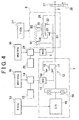
- the main power source 1 mainly includes an internal combustion engine (hereinafter, simply referred to as "engine") 10, a motor/generator (hereinafter, referred to as “first motor/generator” or “MG1”) 11, and a planetary gear 12 which serves as a torque combining splitting mechanism for combining torque of the engine 10 and torque of the first motor/generator 11, and distributing torque to the engine 10 and the first motor/generator 11.
- the engine 10 is a known power device which outputs power by burning fuel, such as a gasoline engine or a diesel engine.
- An operating state of the engine 10, such as a throttle valve opening degree (an intake air amount), a fuel supply amount, and ignition timing, can be electrically controlled.
- the control thereof is performed, for example, by an electronic control unit (E-ECU) 13 which mainly includes a microcomputer.
- E-ECU electroniceeeCU 13 which mainly includes a microcomputer.
- the first motor/generator 11 is a permanent magnetic synchronous motor.
- the first motor/generator 11 functions both as the motor and the generator.
- the first motor/generator 11 is connected, through an inverter 14, to an electric power storage device 15 such as a battery.
- an electronic control unit (MG1-ECU) 16 which mainly includes a microcomputer is provided.
- a stator (not shown) of the first motor/generator 11 is fixed, and is not rotated.
- the planetary gear mechanism 12 is a known gear mechanism which includes three rotating elements, and which produces a differential effect.
- the three rotating elements are a sun gear 17 which is an external gear; a ring gear 18 which is an internal gear provided concentrically with the sun gear 17; and a carrier 19 which maintains a pinion that is engaged with the sun gear 17 and the ring gear 18 such that the pinion can be rotated around an axis thereof, and can move around the sun gear 17.
- the output shaft of the engine 10 is connected, through a damper 20, to the carrier 19 which is a first rotating element.
- the carrier 19 serves as an input element.
- the rotor (not shown) of the first motor/generator 11 is connected to the sun gear 17 which is a second rotating element. Accordingly, the sun gear 17 serves as a reaction force element. Also, the ring gear 18 which is a third rotating element serves as an output element. The ring gear 18 is connected to the output member (i.e., the output shaft) 2.
- the transmission 6 includes one set of Ravigneaux type planetary gear mechanism. That is, a first sun gear (S1) 21 and a second sun gear (S2) 22 are provided. Each of the first sun gear 21 and the second sun gear 22 is an external gear.
- a first pinion 23 is engaged with the first sun gear 21.
- a second pinion 24 is engaged with the first pinion 23.
- the second pinion 24 is engaged with a ring gear (R) 25 which is provided concentrically with each of the sun gears 21 and 22.
- a carrier (C) 26 maintains each of the pinions 23 and 24 such that each of the pinions 23 and 24 can be rotated around the axis thereof, and can be moved around the sun gear.
- the second sun gear 22 is engaged with the second pinion 24.
- the first sun gear 21, the ring gear 25, and the pinions 23 and 24 constitute a mechanism equivalent to a double pinion type planetary gear mechanism.
- the second sun gear 22, the ring gear 25, and the second pinion 24 constitute a mechanism equivalent to a single pinion planetary gear mechanism.
- a first brake B1 which selectively fixes the first sun gear 21 is provided.
- a second brake B2 which selectively fixes the ring gear 25 is provided.
- Each of the brakes B1 and B2 is a so-called friction engagement device which produces engagement force using frictional force.
- multiple disc type engagement devices, or band type engagement devices may be employed. Torque capacity of each of the brakes B1 and B2 is continuously changed according to the engagement force caused by hydraulic pressure.
- the assist power source 5 is connected to the second sun gear 22, and the carrier 26 is connected to the output shaft 2.
- a parking gear 37 which fixes the output shaft 2 so that a vehicle is maintained in a parked state is fitted to the output shaft 2.
- a parking lock pole 38 is provided. The parking lock ball 38 is engaged with the parking gear 37 so as to stop the rotation thereof when a parking position is selected by a shifting device (not shown).
- the second sun gear 22 serves as a so-called input element, and the carrier 26 serves as an output element.
- a high shift speed is achieved at the gear ratio that is equal to or greater than "1".
- a low shift speed is achieved at the gear ratio that is greater than the gear ratio at which the high shift speed is achieved. Shifting between the shift speeds is performed based on a running state such as a vehicle speed or required driving force (or the accelerator angle). More specifically, a shift speed region is defined in advance as a map (shift diagram), and control is performed such that one of the shift speeds is achieved according to the detected running state.
- an electronic control unit (T-ECU) 27 which mainly includes a microcomputer is provided.
- a motor/generator (hereinafter, referred to as "second motor/generator” or “MG2”) is employed as the assist power source 5, a motor/generator (hereinafter, referred to as "second motor/generator” or “MG2”) is employed.
- This motor/generator 5 can output torque for power running, and can regenerate energy.
- An example of the second motor/generator 5 is a permanent magnetic synchronous motor.
- the rotor (not shown) thereof is connected to the second sun gear 22.
- the second motor/generator 5 is connected to a battery 29 through an inverter 28.
- the inverter 28 is controlled by an electronic control unit (MG2-ECU) 30 which mainly includes a microcomputer, whereby power running and energy regeneration are controlled, and torque at the time of power running and torque at the time of energy regeneration are controlled.
- the battery 29 and the electronic control unit 30 can be integrated with the battery (electric power storage device) 15 and the electronic control unit 16.
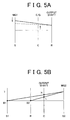
- FIG. 5A is a collinear diagram relating to the single pinion type planetary gear mechanism 12 which serves as the aforementioned torque combining splitting mechanism.
- the reaction torque of the first motor/generator 11 is input to the sun gear (S) 17 against the torque input to the carrier (C) 19 from the engine 10
- the torque input to the carrier (C) 19 is increased or decreased according to the torque input to sun gear (S) 17 and the gear ratio of the planetary gear mechanism 12, and the resultant torque is output from the ring gear (R) 18 which is the output element.
- the rotor of the first motor/generator 11 is rotated by the torque, and the first motor/generator 11 functions as the generator.
- the rotational speed of the engine 10 can be continuously changed by increasing or decreasing the rotational speed of the first motor/generator 11. That is, the rotational speed of the engine 10 can be set to an engine rotational speed at which the fuel efficiency becomes optimal by controlling the first motor/generator 11.
- FIG. 5B is a collinear diagram relating to the Ravigneaux type planetary gear mechanism constituting the transmission 6. That is, when the ring gear 25 is fixed by the second brake B2, a low speed L is achieved. The torque output from the second motor/generator 5 is amplified according to the gear ratio, and the amplified torque is applied to the output shaft 2. Meanwhile, when the first sun gear 21 is fixed by the first brake B1, a high speed H is achieved at the gear ratio which is less than the gear ratio at which the low speed L is achieved. The gear ratio at which the high speed H is achieved is also greater than "1". Therefore, the torque output from the second motor/generator 5 is increased according to the gear ratio, and the increased torque is applied to the output shaft 2.
- the output torque of the second motor/generator 5 is increased according to the gear ratio, and the increased torque is applied to the output shaft 2.
- the torque applied to the output shaft 2 is influenced by the torque capacity of the brake B 1 or B2, inertia torque caused by a change in the rotational speed, and the like.
- the torque applied to the output shaft 2 is positive torque when the second motor/generator 5 is in a driving state.
- the torque applied to the output shaft 2 is negative torque when the second motor/generator 5 is in a driven state.
- the aforementioned hybrid drive apparatus includes two power sources, that are, the main power source 1 and the assist power source 5. Therefore, these two power sources are effectively used so as to improve fuel efficiency and to reduce the amount of exhaust gas while the vehicle runs. Also, even in a case where the engine 10 is driven, the rotational speed of the engine 10 is controlled using the first motor/generator 11 so that the fuel efficiency becomes optimal. Further, during coasting, inertia energy of the vehicle is recovered to generate electric power. In a case where the second motor/generator 5 is driven for torque assist, when the vehicle speed is low, the shift speed is set to the low speed L in the transmission 6, and the torque applied to the output shaft 2 is increased. When the vehicle speed has become high, the shift speed is set to the high speed H in the transmission 6, and the rotational speed of the second motor/generator 5 is relatively decreased so as to reduce loss, whereby torque assist is efficiently performed.
- the aforementioned hybrid vehicle can run using power produced by the engine 10. Also, the hybrid vehicle can run using the engine 10 and the second motor/generator 5. Further, the hybrid vehicle can run using only the second motor/generator 5.
- One of these running modes is selected based on required driving force, the vehicle speed, and the like. For example, when a charge amount of the battery is sufficient, and the required driving force is relatively small, or when a mode for taking off quietly is manually selected, the running mode in which the vehicle runs using the second motor/generator 5 like an electric vehicle (hereinafter, referred to as "EV running") is selected, and the engine 10 is stopped.
- EV running electric vehicle
- E/G running the running mode in which the vehicle runs using the engine 10
- the shift speed in the transmission 6 is set by changing the engagement/disengagement state of each of the first brake B1 and the second brake B2, as described above.
- Each of the first brake B1 and the second brake B2 is engaged/disengaged by controlling hydraulic pressure supplied to each of the first brake B1 and the second brake B2 according to the torque transmitted by the transmission 6.
- a relationship between the torque transmitted by the transmission 6 and the hydraulic pressure is stored in a form of a map. Accordingly, in order to perform shifting quickly or by the minimum hydraulic pressure, it is necessary to correctly detect the relationship between the torque transmitted by the transmission 6 and a hydraulic pressure command value. Therefore, control described below is performed.
- FIG. 1 is a flowchart showing learning control for detecting the relationship between the torque and the hydraulic pressure command value. This control is performed when the torque of the second motor/generator does not need to be transmitted, for example, when a parking position is selected as a running range. Also, this learning control may be performed when the vehicle is adjusted on a production line.
- a target rotational speed of feedback control is set so that the rotational speed of the second motor/generator 5 becomes equal to the predetermined target rotational speed (step S01).
- This target rotational speed is set to a predetermined point on a shift diagram. Plural target rotational speeds may be set.
- step S02 control of the rotational speed of the second motor/generator 5 is started (step S02).
- step S03 motor torque Tmini is detected and stored (step S03).
- This motor torque Tmini is equivalent to drag torque of the brake, and can be obtained based on a value of electric current flowing in the second motor/generator 5.
- the torque Tmini constantly fluctuates, an average value may be obtained at predetermined time intervals, or smoothing processing such as filter processing may be performed.
- step S04 motor torque Tminig output from the second motor/generator 5 starts to be increased. That is, when the hydraulic pressure is supplied to the brake B1 (or B2), a pack clearance which has been generated in the brake B1 (or B2) is gradually reduced (gradually becomes small), and accordingly the torque transmitted through lubricating oil between friction surfaces, that is, the drag torque is increased, which leads to an increase in the motor torque Tminig.
- the predetermined value ⁇ is an expected value of an increase amount of the motor torque when the brake B1 starts to transmit the torque.
- the predetermined value ⁇ is obtained in advance through experiments or calculation. Since this predetermined value ⁇ is considered, it can be determined whether the engagement of the brake B1 (or B2) has been started while preventing influence of production deviation, noise, or the like. Since this motor torque Tminig constantly fluctuates, the average value may be obtained at predetermined time intervals, or smoothing processing such as filter processing may be performed.
- step S05 When a negative determination is made in step S05, no particular process is performed, and the routine is finished. Then, the motor torque Tminig continues to be increased until an affirmative determination is made in step S05. Meanwhile, when an affirmative determination is made in step S05, that is, when the engagement of the brake B1 (or B2) has been completed, a hydraulic pressure command value Pbt at this time point is detected (step S06). Thus, necessary torque when the brake B1 (or B2) is engaged can be detected.
- This control is performed for the brake B1 first, and then the control is performed for the brake B2. However, the control may be performed for the brake B2 first, and then the control may be performed for the brake B1.
- the T-ECU 27 renews a torque - hydraulic pressure conversion map which is stored in the T-ECU 27 (step S07). Then, learning is finished (step S08).
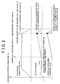
- FIG. 2 is a time chart showing a change with time.
- learning is started (a time point A), and the target rotational speed of the second motor/generator 5 is set (this process corresponds to step S01).
- the second motor/generator 5 starts to be rotated (this process corresponds to step S02)
- the motor torque during this time period is detected (this process corresponds to step S03, from the time point A to a time point B).
- the detected torque is drag torque.
- step S04 the time point B
- the motor torque starts to be increased in accordance with the engagement hydraulic pressure command value.
- This increase in the motor torque is caused mainly by the drag torque.
- the engagement proceeds (from the time point B to a time point C), and the motor torque reaches a value obtained by adding the predetermined value ⁇ to the drag torque, that is, a predetermined torque transmission point that has been obtained in advance through experiments or calculation (this process corresponds to step S05, the time point C)
- the hydraulic pressure command value Pbt at this time point is stored (this process corresponds to step S06).
- this time period that is, during a time period from the time point B to the time point C, the rotational speed of the second motor/generator 5 is maintained at a constant value.
- the hydraulic command value is set to zero, and the target rotational speed of the motor is set to zero. Then, the control is finished (from the time point C to a time point D).
- the output torque corresponds to the torque capacity of the brake B1 (or B2)
- the output torque of the second motor/generator 5 reaches the predetermined value
- the initial torque of the second motor/generator 5 is detected while the engagement control amount is zero, the initial torque is detected as the drag torque of the brake B2 (or B2). Therefore, it is possible to accurately detect the drag torque of the brake B1 (or B2). Also, when the output torque of the second motor/generator 5 exceeds the torque obtained by adding the predetermined value to the drag torque while the engagement control amount is changed, the relationship between the engagement control amount and the torque capacity of the brake B1 (or B2) is learned. Therefore, it is possible to accurately learn the initial characteristic of the brake B1 (or B2) considering the drag torque.
- step S02 can be regarded as “maintaining means”, and functional means in step S04 can be regarded as “changing means”.
- functional means in step S06 can be regarded as “learning means”, and functional means in step S03 can be regarded as "detecting means”.
Abstract
Description
- The invention relates to a drive apparatus of a hybrid vehicle including plural driving force sources. More particularly, the invention relates to a control apparatus and a control method which control torque capacity between a motor having a torque assist function and an output member.
- A hybrid drive apparatus includes a motor or a motor/generator in addition to an internal combustion engine as a driving source, in order to operate the internal combustion engine as efficiently as possible. An example of the hybrid drive apparatus is disclosed in Japanese Patent Application Publication No. JP-A-9-322307. In the hybrid drive apparatus, an internal combustion engine, a motor/generator, and a rotation shaft are connected to a planetary gear mechanism which produces a differential effect. Torque output from the internal combustion engine is distributed to the motor/generator and the rotation shaft, that is, reaction force torque is provided by the motor/generator, whereby a rotational speed of the internal combustion engine and torque output to the rotation shaft are controlled.
- Accordingly, the internal combustion engine can be controlled so as to be operated at an operating point where the optimal fuel efficiency can be achieved, and a substantial gear ratio can be continuously changed. However, in order to further improve efficiency of transmitting power, and to make it possible to achieve various operating states, a stepped transmission may be provided on an engine side of an output shaft. In the apparatus disclosed in the Japanese Patent Application Publication No. JP-A-9-322307, the rotation shaft serves as an input shaft of an automatic transmission in which plural forward speeds can be set using a friction engagement device.
- The friction engagement device is configured such that torque capacity is changed according to engagement hydraulic pressure. Therefore, in order to perform shifting without causing a shock, it is necessary to appropriately control the engagement hydraulic pressure at the time of shifting transition. Accordingly, in the Japanese Patent Application Publication No. JP-A-9-322307, torque of the motor/generator is controlled so that an input rotational speed of the automatic transmission is changed according to a target rotational speed at the time of shifting. Based on a correction amount of the torque input to the input shaft, a duty ratio of a solenoid valve which controls initial hydraulic pressure of the friction engagement device relating to shifting is corrected. A correction amount of the duty ratio is stored so that the initial hydraulic pressure is changed at the time of shifting.
- The shifting in the automatic transmission proceeds as engagement or disengagement of the friction engagement device proceeds. In addition, a predetermined rotational speed such as the input rotational speed is gradually changed at the time of shifting. Accordingly, if the actual rotational speed is different from the target rotational speed, there is excess or deficiency of the rotational speed when the friction engagement device is engaged or disengaged. This is caused by excess or deficiency of engagement pressure or disengagement pressure of the friction engagement device with respect to the torque. Accordingly, in the Japanese Patent Publication Application No. JP-A-9-322307, the torque is controlled by the motor/generator so that the input rotational speed becomes close to the target rotational speed. As a result, the correction amount of the torque of the motor/generator corresponds to the excess or deficiency of the engagement pressure or the disengagement pressure of the friction engagement device. Therefore, the correction amount of the torque is used for correcting the initial hydraulic pressure of the friction engagement device.
- Since the target rotational speed is changed with time when shifting is performed, the correction amount of the torque is increased or decreased with time in the case where the torque is corrected so that the input rotational speed becomes close to the target rotational speed. Meanwhile, a relationship between specific torque capacity of the friction engagement device and hydraulic pressure to be applied to the friction engagement device is static. The correction value used for correcting the initial hydraulic pressure or initial characteristic of the friction engagement device is an average value of the correction amounts obtained during shifting, or a value obtained by numerical processing. In other words, the average value of the correction values obtained when the engagement or disengagement has already proceeded is employed as the correction value of the initial hydraulic pressure in an initial stage of engagement or disengagement. Therefore, the characteristic of the friction engagement device in the initial stage of engagement or disengagement cannot be accurately reflected when the initial hydraulic pressure is corrected. Thus, torque control using the friction engagement device may become different from ideal torque control, and accordingly a shock may be caused or a driver may feel that driving force is insufficient.
- Another prior art document, US 5 951 614, shows a control apparatus for a hybrid drive unit with learning means learning a relationship between a hydraulic pressure and a reduction of an input torque.
- It is an object of the invention to provide a control apparatus and a control method for a drive apparatus of a hybrid vehicle, which includes a torque transmitting member whose torque capacity is changed according to an engagement control amount, and which can accurately set a relationship between an engagement control amount and the torque capacity in an initial stage when the torque transmitting member starts to transmit torque.
- According to the invention, a relationship between an engagement control amount and torque capacity of a torque transmitting member is learned based on a change in a behavior or a control amount of a motor, which is caused while the engagement control amount of the torque transmitting member is changed in a drive apparatus of a hybrid vehicle. A first aspect of the invention relates to a control apparatus for a drive apparatus of a hybrid vehicle, in which a motor is connected to an output member connected to a main power source through a torque transmitting member whose torque capacity is changed according to an engagement control amount. The control apparatus includes maintaining means for maintaining a rotational speed of the motor at a predetermined rotational speed; changing means for continuously changing the engagement control amount while the maintaining means maintains the rotational speed of the motor at the predetermined rotational speed; and learning means for learning a relationship between output torque of the motor for maintaining the rotational speed of the motor at the predetermined rotational speed and the engagement control amount when the output torque of the motor reaches a predetermined value while the engagement control amount is changed.
- In the control apparatus for a drive apparatus of a hybrid vehicle, when the engagement control amount of the torque transmitting member which is provided between the motor and the output member is changed while the rotational speed of the motor is maintained at the predetermined rotational speed, torque acting on the motor is changed, and therefore the output torque necessary for maintaining the rotational speed of the motor at the predetermined rotational speed is changed. The output torque of the motor can be accurately detected, for example, based on an electric current value. Since the output torque corresponds to the torque capacity of the torque transmitting member, when the output torque of the motor reaches the predetermined value, it is possible to accurately learn the relationship between the output torque of the motor and the engagement control amount, that is, the relationship between the engagement control amount and the torque capacity of the torque transmitting member, without being influenced by noise or the like. Accordingly, it is possible to accurately learn the characteristic of the torque transmitting member in the initial stage of the engagement.
- The control apparatus for a drive apparatus of a hybrid vehicle may further include detecting means for detecting initial output torque of the motor while the engagement control amount is zero, and the predetermined value may be set to a value obtained by adding predetermined torque to the initial output torque detected by the detecting means.
- In this case, since the initial torque of the motor is detected while the engagement control amount is zero, the initial torque is detected as drag torque of the torque transmitting member. Therefore, it is possible to accurately detect the drag torque of the torque transmitting member. Also, when the output torque of the motor exceeds the torque obtained by adding the predetermined value to the drag torque while the engagement control amount is changed, the relationship between the engagement control amount and the torque capacity of the torque transmitting member is learned. Therefore, it is possible to accurately learn the initial characteristic of the torque transmitting member considering the drag torque.
- A second aspect of the invention relates to a control method for a drive apparatus of a hybrid vehicle in which a motor is connected to an output member connected to a main power source through a torque transmitting member whose torque capacity is changed according to an engagement control amount. The control method includes the steps of maintaining a rotational speed of the motor at a predetermined rotational speed; continuously changing the engagement control amount while maintaining the rotational speed of the motor at the predetermined rotational speed; and learning a relationship between output torque of the motor for maintaining the rotational speed of the motor at the predetermined rotational speed and the engagement control amount when the output torque of the motor reaches a predetermined value while the engagement control amount is changed.
- The foregoing and further objects, features and advantages of the invention will become apparent from the following description of preferred embodiments with reference to the accompanying drawings, wherein like numerals are used to represent like elements and wherein:
- FIG 1 is a flow chart showing learning control for detecting a relationship between torque and hydraulic pressure;
- FIG. 2 is a time chart in a case where control according to the invention is performed;
- FIG. 3 is a schematic diagram showing a drive apparatus for a hybrid vehicle according to the invention;
- FIG. 4 is a skeleton diagram showing the drive apparatus for a hybrid vehicle according to the invention; and
- FIG. 5A and FIG. 5B are collinear diagrams relating to the drive apparatus.
- Hereinafter, an embodiment of the invention will be described. As shown in FIG. 3, in a hybrid drive apparatus according to the embodiment of the invention, torque of a main power source (i.e., a first power source) 1 is transmitted to an
output member 2, and the torque is transmitted from theoutput member 2 to a drive wheel 4 through a differential 3. Meanwhile, an assist power source (i.e., a second power source) 5 is provided. Theassist power source 5 can output driving force for running according to power running control, and regenerate energy according to regenerative control. Theassist power source 5 is connected to theoutput member 2 through atransmission 6. Accordingly, torque transmitted between the assistpower source 5 and theoutput member 2 is increased or decreased according to a gear ratio set in thetransmission 6. - The
transmission 6 can be configured such that the set gear ratio becomes equal to or greater than "1". With this configuration, when the assistpower source 5 outputs torque at the time of power running, the torque output by theassist power source 5 can be increased, and the increased torque can be transmitted to theoutput member 2. Therefore, capacity or size of the assistpower source 5 can be made small. However, since it is preferable to maintain good operating efficiency of the assistpower source 5, for example, when the rotational speed of theoutput member 2 is increased according to a vehicle speed, the gear ratio is reduced so as to decrease the rotational speed of the assistpower source 5. Also, when the rotational speed of theoutput member 2 is decreased, the gear ratio may be increased. - The hybrid drive apparatus will be described more specifically. As shown in FIG. 4, the main power source 1 mainly includes an internal combustion engine (hereinafter, simply referred to as "engine") 10, a motor/generator (hereinafter, referred to as "first motor/generator" or "MG1") 11, and a
planetary gear 12 which serves as a torque combining splitting mechanism for combining torque of theengine 10 and torque of the first motor/generator 11, and distributing torque to theengine 10 and the first motor/generator 11. Theengine 10 is a known power device which outputs power by burning fuel, such as a gasoline engine or a diesel engine. An operating state of theengine 10, such as a throttle valve opening degree (an intake air amount), a fuel supply amount, and ignition timing, can be electrically controlled. The control thereof is performed, for example, by an electronic control unit (E-ECU) 13 which mainly includes a microcomputer. - An example of the first motor/generator 11 is a permanent magnetic synchronous motor. The first motor/generator 11 functions both as the motor and the generator. The first motor/generator 11 is connected, through an
inverter 14, to an electricpower storage device 15 such as a battery. By controlling theinverter 14, the output torque or regenerative torque of the first motor/generator 11 is appropriately set. In order to perform this control, an electronic control unit (MG1-ECU) 16 which mainly includes a microcomputer is provided. A stator (not shown) of the first motor/generator 11 is fixed, and is not rotated. - Further, the
planetary gear mechanism 12 is a known gear mechanism which includes three rotating elements, and which produces a differential effect. The three rotating elements are asun gear 17 which is an external gear; aring gear 18 which is an internal gear provided concentrically with thesun gear 17; and acarrier 19 which maintains a pinion that is engaged with thesun gear 17 and thering gear 18 such that the pinion can be rotated around an axis thereof, and can move around thesun gear 17. The output shaft of theengine 10 is connected, through adamper 20, to thecarrier 19 which is a first rotating element. In other words, thecarrier 19 serves as an input element. - Meanwhile, the rotor (not shown) of the first motor/generator 11 is connected to the
sun gear 17 which is a second rotating element. Accordingly, thesun gear 17 serves as a reaction force element. Also, thering gear 18 which is a third rotating element serves as an output element. Thering gear 18 is connected to the output member (i.e., the output shaft) 2. - In the example shown in FIG. 4, the
transmission 6 includes one set of Ravigneaux type planetary gear mechanism. That is, a first sun gear (S1) 21 and a second sun gear (S2) 22 are provided. Each of thefirst sun gear 21 and thesecond sun gear 22 is an external gear. Afirst pinion 23 is engaged with thefirst sun gear 21. Asecond pinion 24 is engaged with thefirst pinion 23. Thesecond pinion 24 is engaged with a ring gear (R) 25 which is provided concentrically with each of the sun gears 21 and 22. A carrier (C) 26 maintains each of thepinions pinions second sun gear 22 is engaged with thesecond pinion 24. Accordingly, thefirst sun gear 21, thering gear 25, and thepinions second sun gear 22, thering gear 25, and thesecond pinion 24 constitute a mechanism equivalent to a single pinion planetary gear mechanism. - A first brake B1 which selectively fixes the
first sun gear 21 is provided. A second brake B2 which selectively fixes thering gear 25 is provided. Each of the brakes B1 and B2 is a so-called friction engagement device which produces engagement force using frictional force. As the brakes B1 and B2, multiple disc type engagement devices, or band type engagement devices may be employed. Torque capacity of each of the brakes B1 and B2 is continuously changed according to the engagement force caused by hydraulic pressure. Also, the assistpower source 5 is connected to thesecond sun gear 22, and thecarrier 26 is connected to theoutput shaft 2. Further, aparking gear 37 which fixes theoutput shaft 2 so that a vehicle is maintained in a parked state is fitted to theoutput shaft 2. Also, aparking lock pole 38 is provided. Theparking lock ball 38 is engaged with theparking gear 37 so as to stop the rotation thereof when a parking position is selected by a shifting device (not shown). - Accordingly, in the
aforementioned transmission 6, thesecond sun gear 22 serves as a so-called input element, and thecarrier 26 serves as an output element. When the first brake B 1 is engaged, a high shift speed is achieved at the gear ratio that is equal to or greater than "1". When the second brake B2 is engaged instead of the first brake B1, a low shift speed is achieved at the gear ratio that is greater than the gear ratio at which the high shift speed is achieved. Shifting between the shift speeds is performed based on a running state such as a vehicle speed or required driving force (or the accelerator angle). More specifically, a shift speed region is defined in advance as a map (shift diagram), and control is performed such that one of the shift speeds is achieved according to the detected running state. In order to perform this control, an electronic control unit (T-ECU) 27 which mainly includes a microcomputer is provided. - In the example shown in FIG. 4, as the
assist power source 5, a motor/generator (hereinafter, referred to as "second motor/generator" or "MG2") is employed. This motor/generator 5 can output torque for power running, and can regenerate energy. An example of the second motor/generator 5 is a permanent magnetic synchronous motor. The rotor (not shown) thereof is connected to thesecond sun gear 22. Further, the second motor/generator 5 is connected to abattery 29 through aninverter 28. Theinverter 28 is controlled by an electronic control unit (MG2-ECU) 30 which mainly includes a microcomputer, whereby power running and energy regeneration are controlled, and torque at the time of power running and torque at the time of energy regeneration are controlled. Thebattery 29 and theelectronic control unit 30 can be integrated with the battery (electric power storage device) 15 and theelectronic control unit 16. Also, a stator (not shown) of the second motor/generator 5 is fixed, and is not rotated. - FIG. 5A is a collinear diagram relating to the single pinion type
planetary gear mechanism 12 which serves as the aforementioned torque combining splitting mechanism. When the reaction torque of the first motor/generator 11 is input to the sun gear (S) 17 against the torque input to the carrier (C) 19 from theengine 10, the torque input to the carrier (C) 19 is increased or decreased according to the torque input to sun gear (S) 17 and the gear ratio of theplanetary gear mechanism 12, and the resultant torque is output from the ring gear (R) 18 which is the output element. In this case, the rotor of the first motor/generator 11 is rotated by the torque, and the first motor/generator 11 functions as the generator. Also, when the rotational speed (output rotational speed) of thering gear 18 is maintained at a constant value, the rotational speed of theengine 10 can be continuously changed by increasing or decreasing the rotational speed of the first motor/generator 11. That is, the rotational speed of theengine 10 can be set to an engine rotational speed at which the fuel efficiency becomes optimal by controlling the first motor/generator 11. - Further, as shown by a chain line in FIG. 5A, when the
engine 10 is stopped while the vehicle is running, the first motor/generator 11 is rotated in a reverse direction. When the first motor/generator 11 is caused to function as the motor and to output torque in a normal rotational direction thereafter, torque is applied to the output shaft of theengine 10 which is connected to thecarrier 19 so that the output shaft is rotated in the normal rotational direction. Accordingly, theengine 10 can be started (motoring or cranking can be performed) by the first motor/generator 11. In this case, torque is applied to theoutput shaft 2 in such a direction as to stop the rotation thereof. Accordingly, the driving torque for running can be maintained by controlling the torque output from the second motor/generator 5, and theengine 10 can be smoothly started at the same time. This hybrid type is referred to as "mechanical split type" or "split type". - FIG. 5B is a collinear diagram relating to the Ravigneaux type planetary gear mechanism constituting the
transmission 6. That is, when thering gear 25 is fixed by the second brake B2, a low speed L is achieved. The torque output from the second motor/generator 5 is amplified according to the gear ratio, and the amplified torque is applied to theoutput shaft 2. Meanwhile, when thefirst sun gear 21 is fixed by the first brake B1, a high speed H is achieved at the gear ratio which is less than the gear ratio at which the low speed L is achieved. The gear ratio at which the high speed H is achieved is also greater than "1". Therefore, the torque output from the second motor/generator 5 is increased according to the gear ratio, and the increased torque is applied to theoutput shaft 2. - While the shift speed is set to the low speed L or high speed H in a steady state, the output torque of the second motor/
generator 5 is increased according to the gear ratio, and the increased torque is applied to theoutput shaft 2. However, in a shift transition state, the torque applied to theoutput shaft 2 is influenced by the torque capacity of the brake B 1 or B2, inertia torque caused by a change in the rotational speed, and the like. The torque applied to theoutput shaft 2 is positive torque when the second motor/generator 5 is in a driving state. The torque applied to theoutput shaft 2 is negative torque when the second motor/generator 5 is in a driven state. - The aforementioned hybrid drive apparatus includes two power sources, that are, the main power source 1 and the assist
power source 5. Therefore, these two power sources are effectively used so as to improve fuel efficiency and to reduce the amount of exhaust gas while the vehicle runs. Also, even in a case where theengine 10 is driven, the rotational speed of theengine 10 is controlled using the first motor/generator 11 so that the fuel efficiency becomes optimal. Further, during coasting, inertia energy of the vehicle is recovered to generate electric power. In a case where the second motor/generator 5 is driven for torque assist, when the vehicle speed is low, the shift speed is set to the low speed L in thetransmission 6, and the torque applied to theoutput shaft 2 is increased. When the vehicle speed has become high, the shift speed is set to the high speed H in thetransmission 6, and the rotational speed of the second motor/generator 5 is relatively decreased so as to reduce loss, whereby torque assist is efficiently performed. - The aforementioned hybrid vehicle can run using power produced by the
engine 10. Also, the hybrid vehicle can run using theengine 10 and the second motor/generator 5. Further, the hybrid vehicle can run using only the second motor/generator 5. One of these running modes is selected based on required driving force, the vehicle speed, and the like. For example, when a charge amount of the battery is sufficient, and the required driving force is relatively small, or when a mode for taking off quietly is manually selected, the running mode in which the vehicle runs using the second motor/generator 5 like an electric vehicle (hereinafter, referred to as "EV running") is selected, and theengine 10 is stopped. For example, when the accelerator pedal is depressed to a large extent thereafter, and the required driving force is increased, when the charge amount of the battery is decreased, or when the mode for taking off quietly is manually changed to a mode for normal running, theengine 10 is started, and the running mode in which the vehicle runs using the engine 10 (hereinafter, referred to as "E/G running") is selected. - Meanwhile, the shift speed in the
transmission 6 is set by changing the engagement/disengagement state of each of the first brake B1 and the second brake B2, as described above. Each of the first brake B1 and the second brake B2 is engaged/disengaged by controlling hydraulic pressure supplied to each of the first brake B1 and the second brake B2 according to the torque transmitted by thetransmission 6. A relationship between the torque transmitted by thetransmission 6 and the hydraulic pressure is stored in a form of a map. Accordingly, in order to perform shifting quickly or by the minimum hydraulic pressure, it is necessary to correctly detect the relationship between the torque transmitted by thetransmission 6 and a hydraulic pressure command value. Therefore, control described below is performed. - FIG. 1 is a flowchart showing learning control for detecting the relationship between the torque and the hydraulic pressure command value. This control is performed when the torque of the second motor/generator does not need to be transmitted, for example, when a parking position is selected as a running range. Also, this learning control may be performed when the vehicle is adjusted on a production line.
- First, a target rotational speed of feedback control is set so that the rotational speed of the second motor/
generator 5 becomes equal to the predetermined target rotational speed (step S01). This target rotational speed is set to a predetermined point on a shift diagram. Plural target rotational speeds may be set. - Then, control of the rotational speed of the second motor/
generator 5 is started (step S02). When the rotational speed of the second motor/generator 5 becomes equal to the target rotational speed after the control of the rotational speed is started, motor torque Tmini is detected and stored (step S03). This motor torque Tmini is equivalent to drag torque of the brake, and can be obtained based on a value of electric current flowing in the second motor/generator 5. In other words, it is possible to detect the motor torque when the hydraulic pressure command value is zero, that is, the motor torque when the brake B1 (or B2) is disengaged. Since the torque Tmini constantly fluctuates, an average value may be obtained at predetermined time intervals, or smoothing processing such as filter processing may be performed. - After the control of the rotational speed of the second motor/
generator 5 is started, and the rotational speed becomes stable, the engagement of the brake B1 (or B2) is started. More specifically, the hydraulic pressure supplied to the brake B 1 (or B2) starts to be increased (step S04). Thus, motor torque Tminig output from the second motor/generator 5 starts to be increased. That is, when the hydraulic pressure is supplied to the brake B1 (or B2), a pack clearance which has been generated in the brake B1 (or B2) is gradually reduced (gradually becomes small), and accordingly the torque transmitted through lubricating oil between friction surfaces, that is, the drag torque is increased, which leads to an increase in the motor torque Tminig. - Then, it is determined whether the motor torque Tminig exceeds a value obtained by a predetermined value α to the motor torque Tmini (step S05). The predetermined value α is an expected value of an increase amount of the motor torque when the brake B1 starts to transmit the torque. The predetermined value α is obtained in advance through experiments or calculation. Since this predetermined value α is considered, it can be determined whether the engagement of the brake B1 (or B2) has been started while preventing influence of production deviation, noise, or the like. Since this motor torque Tminig constantly fluctuates, the average value may be obtained at predetermined time intervals, or smoothing processing such as filter processing may be performed.
- When a negative determination is made in step S05, no particular process is performed, and the routine is finished. Then, the motor torque Tminig continues to be increased until an affirmative determination is made in step S05. Meanwhile, when an affirmative determination is made in step S05, that is, when the engagement of the brake B1 (or B2) has been completed, a hydraulic pressure command value Pbt at this time point is detected (step S06). Thus, necessary torque when the brake B1 (or B2) is engaged can be detected. This control is performed for the brake B1 first, and then the control is performed for the brake B2. However, the control may be performed for the brake B2 first, and then the control may be performed for the brake B1.
- Since the control is performed, two sets of values can be calculated. That is, necessary hydraulic pressure when the brake B1 is disengaged and necessary hydraulic pressure when the brake B 1 is engaged, and necessary hydraulic pressure when the brake B2 is disengaged and necessary hydraulic pressure when the brake B2 is engaged are calculated. Based on the two sets of the values, the T-
ECU 27 renews a torque - hydraulic pressure conversion map which is stored in the T-ECU 27 (step S07). Then, learning is finished (step S08). - Next, a change with time in the aforementioned embodiment will be described. FIG. 2 is a time chart showing a change with time. First, learning is started (a time point A), and the target rotational speed of the second motor/
generator 5 is set (this process corresponds to step S01). When the second motor/generator 5 starts to be rotated (this process corresponds to step S02), the motor torque during this time period is detected (this process corresponds to step S03, from the time point A to a time point B). The detected torque is drag torque. - After the hydraulic pressure command value for the brake B1 (or B2) is gradually increased from zero (this process corresponds to step S04, the time point B), the motor torque starts to be increased in accordance with the engagement hydraulic pressure command value. This increase in the motor torque is caused mainly by the drag torque. When the engagement proceeds (from the time point B to a time point C), and the motor torque reaches a value obtained by adding the predetermined value α to the drag torque, that is, a predetermined torque transmission point that has been obtained in advance through experiments or calculation (this process corresponds to step S05, the time point C), the hydraulic pressure command value Pbt at this time point is stored (this process corresponds to step S06). During this time period, that is, during a time period from the time point B to the time point C, the rotational speed of the second motor/
generator 5 is maintained at a constant value. - After the hydraulic pressure command value is stored, the hydraulic command value is set to zero, and the target rotational speed of the motor is set to zero. Then, the control is finished (from the time point C to a time point D).
- As has described so far, when an engagement control amount of the brake B1 (or B2) that is provided between the second motor/
generator 5 and the output shaft is changed while the rotational speed of the second motor/generator 5 is maintained at the predetermined rotational speed, torque acting on the second motor/generator 5 is changed, and therefore, torque necessary for maintaining the rotational speed is changed. The output torque of the second motor/generator 5 can be accurately detected, for example, based on the electric current value. Since the output torque corresponds to the torque capacity of the brake B1 (or B2), when the output torque of the second motor/generator 5 reaches the predetermined value, it is possible to learn the relationship between the output torque of the motor/generator 5 and the engagement control amount, that is, the relationship between the torque capacity of the brake B 1 (or B2) and the engagement control amount, without being influenced by noise or the like. Accordingly, it is possible to accurately learn the characteristic of the brake B 1 (or B2) during the initial state of the engagement. - Also, since the initial torque of the second motor/
generator 5 is detected while the engagement control amount is zero, the initial torque is detected as the drag torque of the brake B2 (or B2). Therefore, it is possible to accurately detect the drag torque of the brake B1 (or B2). Also, when the output torque of the second motor/generator 5 exceeds the torque obtained by adding the predetermined value to the drag torque while the engagement control amount is changed, the relationship between the engagement control amount and the torque capacity of the brake B1 (or B2) is learned. Therefore, it is possible to accurately learn the initial characteristic of the brake B1 (or B2) considering the drag torque. - In the aforementioned embodiment of the invention, functional means in step S02 can be regarded as "maintaining means", and functional means in step S04 can be regarded as "changing means". Also, functional means in step S06 can be regarded as "learning means", and functional means in step S03 can be regarded as "detecting means".
Claims (5)
- A control apparatus for a drive apparatus of a hybrid vehicle, in which a motor (5) is connected to an output member (2) connected to a main power source (1) through a torque transmitting member (B1, B2) whose torque capacity is changed according to an engagement control amount, comprising:maintaining means maintaining a rotational speed of the motor (5) at a predetermined rotational speed;changing means continuously changing the engagement control amount while the maintaining means maintains the rotational speed of the motor (5) at the predetermined rotational speed; andlearning means learning a relationship between output torque of the motor (5) for maintaining the rotational speed of the motor at the predetermined rotational speed and the engagement control amount when the output torque of the motor (5) reaches a predetermined value while the engagement control amount is changed.
- The control apparatus according to claim 1, further comprising:detecting means detecting initial output torque of the motor while the engagement control amount is zero, and the predetermined value is set to a value obtained by adding a predetermined torque (α) to an initial output torque (Tmini) detected by the detecting means.
- The control apparatus according to claim 2, wherein the detecting means detects output torque when the rotational speed of the motor (5) becomes equal to the predetermined rotational speed, as the initial output torque.
- The control apparatus according to any one of claims 1 to 3, wherein the relationship between the output torque of the motor (5) and the engagement control amount is learned at at least one of a time when a parking position is selected as a running range in the hybrid vehicle, and a time when the hybrid vehicle is adjusted on a production line.
- A control method for a drive apparatus of a hybrid vehicle in which a motor (5) is connected to an output member (2) connected to a main power source (1) through a torque transmitting member (B1, B2) whose torque capacity is changed according to an engagement control amount, comprising the steps of:maintaining a rotational speed of the motor at a predetermined rotational speed (S02);continuously changing the engagement control amount while maintaining the rotational speed of the motor at the predetermined rotational speed (S04); andlearning a relationship between output torque of the motor and the engagement control amount when the output torque of the motor for maintaining the rotational speed of the motor at the predetermined rotational speed reaches a predetermined value while the engagement control amount is changed (S06).
Applications Claiming Priority (2)
| Application Number | Priority Date | Filing Date | Title |
|---|---|---|---|
| JP2004087163A JP3982512B2 (en) | 2004-03-24 | 2004-03-24 | Control device for hybrid drive device and control method for hybrid drive device |
| PCT/IB2005/000666 WO2005090109A1 (en) | 2004-03-24 | 2005-03-16 | Control apparatus and control method for drive apparatus of hybrid vehicle |
Publications (2)
| Publication Number | Publication Date |
|---|---|
| EP1628849A1 EP1628849A1 (en) | 2006-03-01 |
| EP1628849B1 true EP1628849B1 (en) | 2007-05-02 |
Family
ID=34962020
Family Applications (1)
| Application Number | Title | Priority Date | Filing Date |
|---|---|---|---|
| EP05726952A Expired - Fee Related EP1628849B1 (en) | 2004-03-24 | 2005-03-16 | Control apparatus and control method for drive apparatus of hybrid vehicle |
Country Status (7)
| Country | Link |
|---|---|
| US (1) | US7789177B2 (en) |
| EP (1) | EP1628849B1 (en) |
| JP (1) | JP3982512B2 (en) |
| KR (1) | KR100741034B1 (en) |
| CN (1) | CN100336675C (en) |
| DE (1) | DE602005001037T2 (en) |
| WO (1) | WO2005090109A1 (en) |
Families Citing this family (25)
| Publication number | Priority date | Publication date | Assignee | Title |
|---|---|---|---|---|
| ATE545560T1 (en) * | 2002-12-25 | 2012-03-15 | Toyota Motor Co Ltd | CONTROL DEVICE OF A HYBRID DRIVE DEVICE |
| US7368886B2 (en) * | 2004-05-14 | 2008-05-06 | General Motors Corporation | Method of testing motor torque integrity in a hybrid electric vehicle |
| US7393297B2 (en) | 2005-11-15 | 2008-07-01 | Gm Global Technology Operations, Inc. | Electrically variable transmissions with three interconnected gearsets |
| JP2008081099A (en) | 2006-08-29 | 2008-04-10 | Nissan Motor Co Ltd | Controller for hybrid car |
| US8032287B2 (en) * | 2007-03-06 | 2011-10-04 | Nissan Motor Co., Ltd. | Control apparatus of driving system for vehicle |
| FR2920383B1 (en) * | 2007-08-28 | 2009-11-20 | Peugeot Citroen Automobiles Sa | METHOD FOR DETERMINING THE RELEASE POINT OF A CLUTCH DEVICE OF A MOTORIZED HYBRID MOTOR VEHICLE |
| JP4949290B2 (en) * | 2008-02-15 | 2012-06-06 | ジヤトコ株式会社 | Driving force control device for electric vehicle |
| DE102008044016A1 (en) * | 2008-11-24 | 2010-05-27 | Robert Bosch Gmbh | Method for detecting an adjusting torque for a hybrid drive |
| CN101746246B (en) * | 2008-12-16 | 2015-05-13 | 神扬科技实业股份有限公司 | Power generation device capable of assisting engine and power generation method |
| JP5212199B2 (en) * | 2009-03-17 | 2013-06-19 | 日産自動車株式会社 | Clutch control device for hybrid vehicle |
| JP5550064B2 (en) | 2009-07-01 | 2014-07-16 | 住友重機械工業株式会社 | Hybrid work machine |
| US8298118B2 (en) * | 2009-07-27 | 2012-10-30 | GM Global Technology Operations LLC | Motor-assist shift control in a hybrid vehicle transmission |
| DE102010053303A1 (en) * | 2010-12-02 | 2012-06-06 | Volkswagen Ag | Method for controlling e.g. MOSFETs, of three-phase inverter of electric machine in motor car, involves exchanging inverter from motor-driven operating mode into generator operation mode if rectified voltage is larger than threshold value |
| CN103328294B (en) * | 2011-01-31 | 2016-10-12 | 铃木株式会社 | Regenerating control device, method for controlling reproduction and motor vehicle driven by mixed power |
| JP5532339B2 (en) | 2011-03-09 | 2014-06-25 | アイシン・エィ・ダブリュ株式会社 | Control device |
| US8475333B2 (en) * | 2011-05-05 | 2013-07-02 | GM Global Technology Operations LLC | Method and apparatus for effecting light-off of a catalytic converter in a hybrid powertrain system |
| JP5786734B2 (en) * | 2012-01-27 | 2015-09-30 | アイシン・エィ・ダブリュ株式会社 | Hybrid drive unit |
| WO2013145093A1 (en) * | 2012-03-26 | 2013-10-03 | トヨタ自動車株式会社 | Hybrid vehicle drive control device |
| JP2015020590A (en) | 2013-07-19 | 2015-02-02 | トヨタ自動車株式会社 | Hybrid vehicle control device |
| JP6145412B2 (en) * | 2014-02-14 | 2017-06-14 | 本田技研工業株式会社 | Power transmission device |
| JP6420461B2 (en) * | 2015-03-17 | 2018-11-07 | ジヤトコ株式会社 | Control device for hybrid vehicle |
| EP3144754A1 (en) * | 2015-09-17 | 2017-03-22 | Siemens Aktiengesellschaft | Damping of load swinging without additional measurement means on the load side |
| JP6337880B2 (en) * | 2015-12-24 | 2018-06-06 | トヨタ自動車株式会社 | Control device for vehicle drive device |
| JP6766966B2 (en) * | 2017-07-18 | 2020-10-14 | アイシン・エィ・ダブリュ株式会社 | Control device |
| KR102596779B1 (en) | 2020-12-31 | 2023-10-31 | 경북대학교 산학협력단 | Method and Apparatus for measuring optical property characterization of 3D printing structures with micro-optic Mach-Zehnder interferometer |
Family Cites Families (14)
| Publication number | Priority date | Publication date | Assignee | Title |
|---|---|---|---|---|
| JP3047792B2 (en) * | 1995-10-18 | 2000-06-05 | トヨタ自動車株式会社 | Hybrid drive |
| US5982045A (en) * | 1996-04-19 | 1999-11-09 | Toyota Jidosha Kabushiki Kaisha | Hybrid vehicle drive system adapted to prevent concurrent mode change and transmission shifting or torque distribution ratio change |
| JP3622338B2 (en) | 1996-05-28 | 2005-02-23 | トヨタ自動車株式会社 | Vehicle shift control device |
| JP3520668B2 (en) * | 1996-06-11 | 2004-04-19 | トヨタ自動車株式会社 | Hybrid vehicle control device |
| JP3775012B2 (en) * | 1997-08-29 | 2006-05-17 | アイシン・エィ・ダブリュ株式会社 | Hybrid drive device for vehicle |
| US5935035A (en) * | 1998-06-24 | 1999-08-10 | General Motors Corporation | Electro-mechanical powertrain |
| JP3384338B2 (en) * | 1998-09-29 | 2003-03-10 | 日産自動車株式会社 | Hybrid vehicle output control device |
| JP3327262B2 (en) * | 1999-10-08 | 2002-09-24 | トヨタ自動車株式会社 | Reverse travel device for vehicles |
| JP3852321B2 (en) * | 2001-10-22 | 2006-11-29 | トヨタ自動車株式会社 | HV drive structure and method with cranking support torque increasing means |
| JP3712193B2 (en) * | 2001-12-10 | 2005-11-02 | 本田技研工業株式会社 | Engagement control method of friction engagement element in power transmission device |
| JP3852402B2 (en) * | 2002-12-25 | 2006-11-29 | トヨタ自動車株式会社 | Control device for hybrid drive |
| JP3758650B2 (en) * | 2003-06-16 | 2006-03-22 | トヨタ自動車株式会社 | Control device for hybrid drive |
| US7261671B2 (en) * | 2003-09-10 | 2007-08-28 | Ford Global Technologies, Llc | Hybrid vehicle powertrain with a multiple-ratio power transmission mechanism |
| JP4296957B2 (en) * | 2004-02-18 | 2009-07-15 | トヨタ自動車株式会社 | Control device for continuously variable transmission for vehicle |
-
2004
- 2004-03-24 JP JP2004087163A patent/JP3982512B2/en not_active Expired - Fee Related
-
2005
- 2005-03-16 EP EP05726952A patent/EP1628849B1/en not_active Expired - Fee Related
- 2005-03-16 US US10/550,738 patent/US7789177B2/en active Active
- 2005-03-16 DE DE602005001037T patent/DE602005001037T2/en active Active
- 2005-03-16 CN CNB2005800002345A patent/CN100336675C/en not_active Expired - Fee Related
- 2005-03-16 KR KR1020057020657A patent/KR100741034B1/en not_active IP Right Cessation
- 2005-03-16 WO PCT/IB2005/000666 patent/WO2005090109A1/en active IP Right Grant
Also Published As
| Publication number | Publication date |
|---|---|
| DE602005001037D1 (en) | 2007-06-14 |
| DE602005001037T2 (en) | 2008-02-14 |
| EP1628849A1 (en) | 2006-03-01 |
| KR20060017506A (en) | 2006-02-23 |
| KR100741034B1 (en) | 2007-07-20 |
| US7789177B2 (en) | 2010-09-07 |
| JP2005273761A (en) | 2005-10-06 |
| CN100336675C (en) | 2007-09-12 |
| WO2005090109A1 (en) | 2005-09-29 |
| US20060196711A1 (en) | 2006-09-07 |
| JP3982512B2 (en) | 2007-09-26 |
| CN1771144A (en) | 2006-05-10 |
Similar Documents
| Publication | Publication Date | Title |
|---|---|---|
| EP1628849B1 (en) | Control apparatus and control method for drive apparatus of hybrid vehicle | |
| US7552003B2 (en) | Control apparatus and control method for hybrid vehicle | |
| JP3514142B2 (en) | Vehicle control device | |
| US6344008B1 (en) | Hybrid vehicle | |
| US8246508B2 (en) | Controller for vehicle drive device | |
| US7017348B2 (en) | Control device for a hybrid vehicle | |
| EP1979214B1 (en) | Control device of vehicle, vehicle, and method of controlling vehicle | |
| WO2012172639A1 (en) | Vehicle control apparatus | |
| JP4281740B2 (en) | Vehicle and control method thereof | |
| JP2008221879A (en) | Controller for vehicle | |
| US10737682B2 (en) | Drive force control system for hybrid vehicle | |
| JP5288984B2 (en) | Hybrid vehicle | |
| JP5821475B2 (en) | Control device for hybrid vehicle | |
| JP3671669B2 (en) | Creep travel control device for hybrid vehicle | |
| JP5673519B2 (en) | Vehicle control device | |
| US10710446B2 (en) | Engine starting system for vehicle | |
| JP3861486B2 (en) | Control device for hybrid vehicle | |
| JP2000166023A (en) | Controller of motor generator for hybrid vehicle | |
| JP7322746B2 (en) | Vehicle speed control device | |
| JP3956536B2 (en) | Hybrid vehicle drive control device | |
| CN110155037B (en) | Vehicle drive control device and vehicle control method | |
| JP6036491B2 (en) | Vehicle control device | |
| JP3952651B2 (en) | Vehicle deceleration control device | |
| JP2003235107A (en) | Control device for vehicle | |
| JP4051913B2 (en) | Powertrain control device |
Legal Events
| Date | Code | Title | Description |
|---|---|---|---|
| PUAI | Public reference made under article 153(3) epc to a published international application that has entered the european phase |
Free format text: ORIGINAL CODE: 0009012 |
|
| 17P | Request for examination filed |
Effective date: 20050923 |
|
| AK | Designated contracting states |
Kind code of ref document: A1 Designated state(s): AT BE BG CH CY CZ DE DK EE ES FI FR GB GR HU IE IS IT LI LT LU MC NL PL PT RO SE SI SK TR |
|
| AX | Request for extension of the european patent |
Extension state: AL BA HR LV MK YU |
|
| GRAP | Despatch of communication of intention to grant a patent |
Free format text: ORIGINAL CODE: EPIDOSNIGR1 |
|
| GRAS | Grant fee paid |
Free format text: ORIGINAL CODE: EPIDOSNIGR3 |
|
| GRAA | (expected) grant |
Free format text: ORIGINAL CODE: 0009210 |
|
| DAX | Request for extension of the european patent (deleted) | ||
| RBV | Designated contracting states (corrected) |
Designated state(s): DE FR GB IT |
|
| AK | Designated contracting states |
Kind code of ref document: B1 Designated state(s): DE FR GB IT |
|
| DAX | Request for extension of the european patent (deleted) | ||
| RBV | Designated contracting states (corrected) |
Designated state(s): DE FR GB IT |
|
| REG | Reference to a national code |
Ref country code: GB Ref legal event code: FG4D |
|
| REF | Corresponds to: |
Ref document number: 602005001037 Country of ref document: DE Date of ref document: 20070614 Kind code of ref document: P |
|
| ET | Fr: translation filed | ||
| PLBE | No opposition filed within time limit |
Free format text: ORIGINAL CODE: 0009261 |
|
| STAA | Information on the status of an ep patent application or granted ep patent |
Free format text: STATUS: NO OPPOSITION FILED WITHIN TIME LIMIT |
|
| 26N | No opposition filed |
Effective date: 20080205 |
|
| REG | Reference to a national code |
Ref country code: GB Ref legal event code: 746 Effective date: 20121219 |
|
| REG | Reference to a national code |
Ref country code: DE Ref legal event code: R084 Ref document number: 602005001037 Country of ref document: DE Effective date: 20121213 |
|
| REG | Reference to a national code |
Ref country code: FR Ref legal event code: PLFP Year of fee payment: 11 |
|
| PGFP | Annual fee paid to national office [announced via postgrant information from national office to epo] |
Ref country code: DE Payment date: 20150310 Year of fee payment: 11 Ref country code: IT Payment date: 20150220 Year of fee payment: 11 |
|
| PGFP | Annual fee paid to national office [announced via postgrant information from national office to epo] |
Ref country code: GB Payment date: 20150311 Year of fee payment: 11 Ref country code: FR Payment date: 20150309 Year of fee payment: 11 |
|
| REG | Reference to a national code |
Ref country code: DE Ref legal event code: R119 Ref document number: 602005001037 Country of ref document: DE |
|
| GBPC | Gb: european patent ceased through non-payment of renewal fee |
Effective date: 20160316 |
|
| REG | Reference to a national code |
Ref country code: FR Ref legal event code: ST Effective date: 20161130 |
|
| PG25 | Lapsed in a contracting state [announced via postgrant information from national office to epo] |
Ref country code: FR Free format text: LAPSE BECAUSE OF NON-PAYMENT OF DUE FEES Effective date: 20160331 Ref country code: GB Free format text: LAPSE BECAUSE OF NON-PAYMENT OF DUE FEES Effective date: 20160316 Ref country code: DE Free format text: LAPSE BECAUSE OF NON-PAYMENT OF DUE FEES Effective date: 20161001 |
|
| PG25 | Lapsed in a contracting state [announced via postgrant information from national office to epo] |
Ref country code: IT Free format text: LAPSE BECAUSE OF NON-PAYMENT OF DUE FEES Effective date: 20160316 |