EP1628606B1 - High-precision material processing device - Google Patents
High-precision material processing device Download PDFInfo
- Publication number
- EP1628606B1 EP1628606B1 EP04735284A EP04735284A EP1628606B1 EP 1628606 B1 EP1628606 B1 EP 1628606B1 EP 04735284 A EP04735284 A EP 04735284A EP 04735284 A EP04735284 A EP 04735284A EP 1628606 B1 EP1628606 B1 EP 1628606B1
- Authority
- EP
- European Patent Office
- Prior art keywords
- laser
- pulses
- focus
- deflection
- pulse
- Prior art date
- Legal status (The legal status is an assumption and is not a legal conclusion. Google has not performed a legal analysis and makes no representation as to the accuracy of the status listed.)
- Expired - Lifetime
Links
- 239000000463 material Substances 0.000 title claims abstract description 101
- 238000012545 processing Methods 0.000 title claims description 29
- 238000007493 shaping process Methods 0.000 claims description 7
- 230000000694 effects Effects 0.000 claims description 5
- 239000000835 fiber Substances 0.000 claims description 4
- 238000000034 method Methods 0.000 abstract description 16
- 210000004087 cornea Anatomy 0.000 description 24
- 230000003287 optical effect Effects 0.000 description 17
- 241000219739 Lens Species 0.000 description 14
- 238000005520 cutting process Methods 0.000 description 12
- 238000000605 extraction Methods 0.000 description 7
- 238000003754 machining Methods 0.000 description 7
- 239000011368 organic material Substances 0.000 description 7
- 238000012937 correction Methods 0.000 description 5
- 230000005855 radiation Effects 0.000 description 5
- 238000001356 surgical procedure Methods 0.000 description 5
- 230000001172 regenerating effect Effects 0.000 description 4
- 230000003595 spectral effect Effects 0.000 description 4
- 230000008859 change Effects 0.000 description 3
- 238000004519 manufacturing process Methods 0.000 description 3
- 208000014733 refractive error Diseases 0.000 description 3
- 239000012780 transparent material Substances 0.000 description 3
- 229910000831 Steel Inorganic materials 0.000 description 2
- 230000009471 action Effects 0.000 description 2
- 230000003044 adaptive effect Effects 0.000 description 2
- 230000003321 amplification Effects 0.000 description 2
- 230000008901 benefit Effects 0.000 description 2
- 238000013461 design Methods 0.000 description 2
- 238000011161 development Methods 0.000 description 2
- 230000018109 developmental process Effects 0.000 description 2
- 238000006073 displacement reaction Methods 0.000 description 2
- 238000001704 evaporation Methods 0.000 description 2
- 230000008020 evaporation Effects 0.000 description 2
- 238000011010 flushing procedure Methods 0.000 description 2
- 239000012634 fragment Substances 0.000 description 2
- 239000011521 glass Substances 0.000 description 2
- 238000003199 nucleic acid amplification method Methods 0.000 description 2
- 230000008569 process Effects 0.000 description 2
- 239000004065 semiconductor Substances 0.000 description 2
- 239000010959 steel Substances 0.000 description 2
- 230000001960 triggered effect Effects 0.000 description 2
- VYZAMTAEIAYCRO-UHFFFAOYSA-N Chromium Chemical compound [Cr] VYZAMTAEIAYCRO-UHFFFAOYSA-N 0.000 description 1
- 229910052691 Erbium Inorganic materials 0.000 description 1
- 240000004322 Lens culinaris Species 0.000 description 1
- WHXSMMKQMYFTQS-UHFFFAOYSA-N Lithium Chemical compound [Li] WHXSMMKQMYFTQS-UHFFFAOYSA-N 0.000 description 1
- 229910052779 Neodymium Inorganic materials 0.000 description 1
- 208000029091 Refraction disease Diseases 0.000 description 1
- FAPWRFPIFSIZLT-UHFFFAOYSA-M Sodium chloride Chemical compound [Na+].[Cl-] FAPWRFPIFSIZLT-UHFFFAOYSA-M 0.000 description 1
- RTAQQCXQSZGOHL-UHFFFAOYSA-N Titanium Chemical compound [Ti] RTAQQCXQSZGOHL-UHFFFAOYSA-N 0.000 description 1
- 229910052769 Ytterbium Inorganic materials 0.000 description 1
- 230000006978 adaptation Effects 0.000 description 1
- 230000004075 alteration Effects 0.000 description 1
- 230000004430 ametropia Effects 0.000 description 1
- 230000009286 beneficial effect Effects 0.000 description 1
- 230000015572 biosynthetic process Effects 0.000 description 1
- 239000003795 chemical substances by application Substances 0.000 description 1
- 229910052804 chromium Inorganic materials 0.000 description 1
- 239000011651 chromium Substances 0.000 description 1
- 210000004240 ciliary body Anatomy 0.000 description 1
- 239000011248 coating agent Substances 0.000 description 1
- 238000000576 coating method Methods 0.000 description 1
- 230000001427 coherent effect Effects 0.000 description 1
- 230000000295 complement effect Effects 0.000 description 1
- 238000005336 cracking Methods 0.000 description 1
- 239000013078 crystal Substances 0.000 description 1
- 210000003298 dental enamel Anatomy 0.000 description 1
- 230000001419 dependent effect Effects 0.000 description 1
- 239000006185 dispersion Substances 0.000 description 1
- 230000002996 emotional effect Effects 0.000 description 1
- 238000005516 engineering process Methods 0.000 description 1
- UYAHIZSMUZPPFV-UHFFFAOYSA-N erbium Chemical compound [Er] UYAHIZSMUZPPFV-UHFFFAOYSA-N 0.000 description 1
- 230000003628 erosive effect Effects 0.000 description 1
- 238000011049 filling Methods 0.000 description 1
- 239000005383 fluoride glass Substances 0.000 description 1
- 238000013467 fragmentation Methods 0.000 description 1
- 238000006062 fragmentation reaction Methods 0.000 description 1
- 238000003384 imaging method Methods 0.000 description 1
- 230000001771 impaired effect Effects 0.000 description 1
- 230000003993 interaction Effects 0.000 description 1
- 210000000554 iris Anatomy 0.000 description 1
- 238000000608 laser ablation Methods 0.000 description 1
- 238000002430 laser surgery Methods 0.000 description 1
- 230000002045 lasting effect Effects 0.000 description 1
- 239000007788 liquid Substances 0.000 description 1
- 229910052744 lithium Inorganic materials 0.000 description 1
- 230000004807 localization Effects 0.000 description 1
- 239000000155 melt Substances 0.000 description 1
- 230000004048 modification Effects 0.000 description 1
- 238000012986 modification Methods 0.000 description 1
- QEFYFXOXNSNQGX-UHFFFAOYSA-N neodymium atom Chemical compound [Nd] QEFYFXOXNSNQGX-UHFFFAOYSA-N 0.000 description 1
- 210000000056 organ Anatomy 0.000 description 1
- 239000004033 plastic Substances 0.000 description 1
- 229920003023 plastic Polymers 0.000 description 1
- 201000010041 presbyopia Diseases 0.000 description 1
- 238000003672 processing method Methods 0.000 description 1
- 238000005086 pumping Methods 0.000 description 1
- 230000009467 reduction Effects 0.000 description 1
- 229910052594 sapphire Inorganic materials 0.000 description 1
- 239000010980 sapphire Substances 0.000 description 1
- 210000003786 sclera Anatomy 0.000 description 1
- 238000000926 separation method Methods 0.000 description 1
- 239000007787 solid Substances 0.000 description 1
- 238000004381 surface treatment Methods 0.000 description 1
- 230000003685 thermal hair damage Effects 0.000 description 1
- 229910052719 titanium Inorganic materials 0.000 description 1
- 239000010936 titanium Substances 0.000 description 1
- 230000009466 transformation Effects 0.000 description 1
- 238000000844 transformation Methods 0.000 description 1
- 238000009834 vaporization Methods 0.000 description 1
- 230000008016 vaporization Effects 0.000 description 1
- 235000012431 wafers Nutrition 0.000 description 1
- 230000003313 weakening effect Effects 0.000 description 1
- NAWDYIZEMPQZHO-UHFFFAOYSA-N ytterbium Chemical compound [Yb] NAWDYIZEMPQZHO-UHFFFAOYSA-N 0.000 description 1
Images


Classifications
-
- A—HUMAN NECESSITIES
- A61—MEDICAL OR VETERINARY SCIENCE; HYGIENE
- A61F—FILTERS IMPLANTABLE INTO BLOOD VESSELS; PROSTHESES; DEVICES PROVIDING PATENCY TO, OR PREVENTING COLLAPSING OF, TUBULAR STRUCTURES OF THE BODY, e.g. STENTS; ORTHOPAEDIC, NURSING OR CONTRACEPTIVE DEVICES; FOMENTATION; TREATMENT OR PROTECTION OF EYES OR EARS; BANDAGES, DRESSINGS OR ABSORBENT PADS; FIRST-AID KITS
- A61F9/00—Methods or devices for treatment of the eyes; Devices for putting-in contact lenses; Devices to correct squinting; Apparatus to guide the blind; Protective devices for the eyes, carried on the body or in the hand
- A61F9/007—Methods or devices for eye surgery
- A61F9/008—Methods or devices for eye surgery using laser
- A61F9/00825—Methods or devices for eye surgery using laser for photodisruption
- A61F9/00827—Refractive correction, e.g. lenticle
-
- A—HUMAN NECESSITIES
- A61—MEDICAL OR VETERINARY SCIENCE; HYGIENE
- A61F—FILTERS IMPLANTABLE INTO BLOOD VESSELS; PROSTHESES; DEVICES PROVIDING PATENCY TO, OR PREVENTING COLLAPSING OF, TUBULAR STRUCTURES OF THE BODY, e.g. STENTS; ORTHOPAEDIC, NURSING OR CONTRACEPTIVE DEVICES; FOMENTATION; TREATMENT OR PROTECTION OF EYES OR EARS; BANDAGES, DRESSINGS OR ABSORBENT PADS; FIRST-AID KITS
- A61F9/00—Methods or devices for treatment of the eyes; Devices for putting-in contact lenses; Devices to correct squinting; Apparatus to guide the blind; Protective devices for the eyes, carried on the body or in the hand
- A61F9/007—Methods or devices for eye surgery
- A61F9/008—Methods or devices for eye surgery using laser
- A61F9/00825—Methods or devices for eye surgery using laser for photodisruption
- A61F9/00836—Flap cutting
-
- B—PERFORMING OPERATIONS; TRANSPORTING
- B23—MACHINE TOOLS; METAL-WORKING NOT OTHERWISE PROVIDED FOR
- B23K—SOLDERING OR UNSOLDERING; WELDING; CLADDING OR PLATING BY SOLDERING OR WELDING; CUTTING BY APPLYING HEAT LOCALLY, e.g. FLAME CUTTING; WORKING BY LASER BEAM
- B23K26/00—Working by laser beam, e.g. welding, cutting or boring
- B23K26/02—Positioning or observing the workpiece, e.g. with respect to the point of impact; Aligning, aiming or focusing the laser beam
- B23K26/06—Shaping the laser beam, e.g. by masks or multi-focusing
- B23K26/062—Shaping the laser beam, e.g. by masks or multi-focusing by direct control of the laser beam
- B23K26/0622—Shaping the laser beam, e.g. by masks or multi-focusing by direct control of the laser beam by shaping pulses
- B23K26/0624—Shaping the laser beam, e.g. by masks or multi-focusing by direct control of the laser beam by shaping pulses using ultrashort pulses, i.e. pulses of 1ns or less
-
- A—HUMAN NECESSITIES
- A61—MEDICAL OR VETERINARY SCIENCE; HYGIENE
- A61F—FILTERS IMPLANTABLE INTO BLOOD VESSELS; PROSTHESES; DEVICES PROVIDING PATENCY TO, OR PREVENTING COLLAPSING OF, TUBULAR STRUCTURES OF THE BODY, e.g. STENTS; ORTHOPAEDIC, NURSING OR CONTRACEPTIVE DEVICES; FOMENTATION; TREATMENT OR PROTECTION OF EYES OR EARS; BANDAGES, DRESSINGS OR ABSORBENT PADS; FIRST-AID KITS
- A61F9/00—Methods or devices for treatment of the eyes; Devices for putting-in contact lenses; Devices to correct squinting; Apparatus to guide the blind; Protective devices for the eyes, carried on the body or in the hand
- A61F9/007—Methods or devices for eye surgery
- A61F9/008—Methods or devices for eye surgery using laser
- A61F2009/00861—Methods or devices for eye surgery using laser adapted for treatment at a particular location
- A61F2009/00865—Sclera
-
- A—HUMAN NECESSITIES
- A61—MEDICAL OR VETERINARY SCIENCE; HYGIENE
- A61F—FILTERS IMPLANTABLE INTO BLOOD VESSELS; PROSTHESES; DEVICES PROVIDING PATENCY TO, OR PREVENTING COLLAPSING OF, TUBULAR STRUCTURES OF THE BODY, e.g. STENTS; ORTHOPAEDIC, NURSING OR CONTRACEPTIVE DEVICES; FOMENTATION; TREATMENT OR PROTECTION OF EYES OR EARS; BANDAGES, DRESSINGS OR ABSORBENT PADS; FIRST-AID KITS
- A61F9/00—Methods or devices for treatment of the eyes; Devices for putting-in contact lenses; Devices to correct squinting; Apparatus to guide the blind; Protective devices for the eyes, carried on the body or in the hand
- A61F9/007—Methods or devices for eye surgery
- A61F9/008—Methods or devices for eye surgery using laser
- A61F2009/00861—Methods or devices for eye surgery using laser adapted for treatment at a particular location
- A61F2009/00868—Ciliary muscles or trabecular meshwork
-
- A—HUMAN NECESSITIES
- A61—MEDICAL OR VETERINARY SCIENCE; HYGIENE
- A61F—FILTERS IMPLANTABLE INTO BLOOD VESSELS; PROSTHESES; DEVICES PROVIDING PATENCY TO, OR PREVENTING COLLAPSING OF, TUBULAR STRUCTURES OF THE BODY, e.g. STENTS; ORTHOPAEDIC, NURSING OR CONTRACEPTIVE DEVICES; FOMENTATION; TREATMENT OR PROTECTION OF EYES OR EARS; BANDAGES, DRESSINGS OR ABSORBENT PADS; FIRST-AID KITS
- A61F9/00—Methods or devices for treatment of the eyes; Devices for putting-in contact lenses; Devices to correct squinting; Apparatus to guide the blind; Protective devices for the eyes, carried on the body or in the hand
- A61F9/007—Methods or devices for eye surgery
- A61F9/008—Methods or devices for eye surgery using laser
- A61F2009/00861—Methods or devices for eye surgery using laser adapted for treatment at a particular location
- A61F2009/0087—Lens
-
- A—HUMAN NECESSITIES
- A61—MEDICAL OR VETERINARY SCIENCE; HYGIENE
- A61F—FILTERS IMPLANTABLE INTO BLOOD VESSELS; PROSTHESES; DEVICES PROVIDING PATENCY TO, OR PREVENTING COLLAPSING OF, TUBULAR STRUCTURES OF THE BODY, e.g. STENTS; ORTHOPAEDIC, NURSING OR CONTRACEPTIVE DEVICES; FOMENTATION; TREATMENT OR PROTECTION OF EYES OR EARS; BANDAGES, DRESSINGS OR ABSORBENT PADS; FIRST-AID KITS
- A61F9/00—Methods or devices for treatment of the eyes; Devices for putting-in contact lenses; Devices to correct squinting; Apparatus to guide the blind; Protective devices for the eyes, carried on the body or in the hand
- A61F9/007—Methods or devices for eye surgery
- A61F9/008—Methods or devices for eye surgery using laser
- A61F2009/00861—Methods or devices for eye surgery using laser adapted for treatment at a particular location
- A61F2009/00872—Cornea
-
- A—HUMAN NECESSITIES
- A61—MEDICAL OR VETERINARY SCIENCE; HYGIENE
- A61F—FILTERS IMPLANTABLE INTO BLOOD VESSELS; PROSTHESES; DEVICES PROVIDING PATENCY TO, OR PREVENTING COLLAPSING OF, TUBULAR STRUCTURES OF THE BODY, e.g. STENTS; ORTHOPAEDIC, NURSING OR CONTRACEPTIVE DEVICES; FOMENTATION; TREATMENT OR PROTECTION OF EYES OR EARS; BANDAGES, DRESSINGS OR ABSORBENT PADS; FIRST-AID KITS
- A61F9/00—Methods or devices for treatment of the eyes; Devices for putting-in contact lenses; Devices to correct squinting; Apparatus to guide the blind; Protective devices for the eyes, carried on the body or in the hand
- A61F9/007—Methods or devices for eye surgery
- A61F9/008—Methods or devices for eye surgery using laser
- A61F2009/00861—Methods or devices for eye surgery using laser adapted for treatment at a particular location
- A61F2009/00874—Vitreous
Definitions
- the invention relates to a device for the precise processing of material and tissue, in particular a laser device for precise, micrometer accurate processing of organic material, preferably an eye.
- the material-processing effect of the laser is limited to the small spatial area of the laser focus (typically a few ⁇ m 3 ), in which the light intensity is high enough to exceed the threshold of the optical breakthrough. Localized to this focus volume, the cohesion of the material is destroyed and creates a cavitation bubble. If the laser focus is directed to a new position for each laser pulse, linear, area or three-dimensional patterns can be generated. The distance between adjacent cavitation bubbles must be approximately equal to their diameter at the end of processing, so that the material is easily mechanically removable along the cuts.
- the existing laser equipment for material processing with femtosecond laser pulses use regenerative amplifiers with repetition rates up to 15 kHz, which amplify individual pulses of a femtosecond oscillator. While the oscillator itself provides only pulse energies in the nanjojoule range, the pulses can be amplified with a regenerative amplifier up to a few millijoules of pulse energy. While these laser sources are suitable for high erosion rate applications per laser pulse, they are not optimal for the precision cutting application described above.
- the laser beam pulses have a pulse length between 100 fs and 10 ns and a pulse frequency of 0.1 kHz to 0.1 MHz, the energy being 200 GW / cm 2 with a pulse length of 50 ps and a focus diameter of 10 micrometers.
- the object of the present invention is therefore to provide a device for the precise machining of material, with which these disadvantages of the prior art are overcome.
- the object is achieved by a device for the precise machining of material, in particular organic material, this device generates cavitation bubbles in the material to be machined, whose diameter is less than 10 microns.
- a pulsed laser beam with a pulse energy of less than 5 ⁇ J is focused to a focus diameter of a few ⁇ m.
- the focus diameter is about 3 ⁇ m and the pulse energy is 1 ⁇ J.
- the device is characterized in that it allows a very fast processing by using a pulse repetition rate of more than 50 kHz. This is of great advantage, in particular for refractive corneal surgery, because it allows an operating time of a few seconds to about 1 minute to be achieved.
- a device for precise machining of material comprising a pulsed laser system with the parameters described above as a beam source, in which by a jet devices with at least one means for beam deflection, a working beam of the beam source can be applied to the material wherein the pulse emission correlates with the beam deflection, and wherein the means for beam deflection comprises means for releasing laser pulses.
- a jet devices with at least one means for beam deflection a working beam of the beam source can be applied to the material wherein the pulse emission correlates with the beam deflection
- the means for beam deflection comprises means for releasing laser pulses.
- Under release is understood to mean that the laser is released for a laser pulse and the laser pulse is triggered as soon as the laser can deliver a laser pulse again according to its maximum repetition rate.
- Correlation of the pulse emission with the beam deflection is understood in particular to mean that the pulse emission can take place when the beam has been directed to a specific point, ie the pulse emission is activated as a function of the beam
- the above object is achieved by a device for precise machining of material, in particular organic material, comprising a pulsed laser system as a beam source, wherein the energy of the radiation about 100 nJ to 10 ⁇ J, preferably 500 nJ to 5 ⁇ J, is.
- the Repetitionsrate the radiation is preferably 50 khz to 1 Mhz, more preferably 100 khz to 500 khz.
- the focus diameter of the radiation is preferably about 500 nm to 10 .mu.m, more preferably 3 .mu.m to 5 .mu.m.
- the pulse duration of the radiation is preferably about 100 fs to 1 ps, more preferably 200 fs to 500 fs.
- the beam shaping and / or beam deflection means or more generally the beam shaping and deflection systems may comprise diffractive or refractive micro-optics or adaptive optics or classical optical systems. With diffractive or refractive elements one can replace several classical or conventional optical elements.
- Said device for the precise processing of material is preferably used for ophthalmological eye treatment, in particular for the correction of the refractive error of an eye.
- the device can be used to cut a flap or lenticle in the cornea to correct the ametropia.
- refractive structures in the cornea for example in the form of areally juxtaposed spots or a point cloud, can be generated with the device according to the invention.
- laser shots can be set directly to produce refractive structures.
- small bubbles can be produced in the eye lens by vaporization of material or liquid.
- very many laser shots with comparatively low energy are required, as can be provided with the device according to the invention.
- the device according to the invention it is possible to introduce targeted cuts into the tissue, for example the eye lens, with the device according to the invention, and thus to improve the curvability and elasticity of the eye lens, since the adjacent tissue parts can now be displaced more easily relative to one another.
- the device for the precise processing of material, in particular organic material is used in this embodiment of the invention as a device for the treatment of presbyopia.
- the beam shaping takes place either conventionally or with diffractive or refractive micro-optics or adaptive optics.
- the beam deflection is preferably carried out via scanning systems.
- Suitable laser beam sources are oscillator-amplifier arrangements, with regenerative amplifiers, chirped-pulse amplifiers (CPA) or multipass amplifiers being particularly suitable for the amplifier.
- CPA chirped-pulse amplifiers
- the mode-locked oscillator in particular disk laser oscillators, fiber laser oscillators, but also bar laser oscillators are suitable.
- the amplifier in particular disk laser amplifiers, fiber laser amplifiers, but also laser beam amplifiers are suitable.
- semiconductor laser diodes are particularly preferable because of their long life, reliability, controllability and their comparatively low manufacturing cost.
- Preferred laser media in the above laser beam sources are doped solid state materials, especially crystals and glasses.
- these are YAG, tungstates, sapphire and fluoride glasses.
- These host materials may preferably be doped with neodymium, erbium, titanium, chromium, lithium or ytterbium. All of these materials are characterized by a spectrally broadband laser emission in the spectral range from 600 nm to 2000 nm and thus include the spectral range between 800 nm and 1200 nm which is particularly suitable for refractive corneal surgery.
- the large spectral bandwidth of the laser emission of the above materials supports an ultra-short laser pulse duration between 50 fs and 1 ps. It is not necessary that the laser itself emits pulses of this pulse duration, but that the preferred pulse duration of about 300 fs is achieved in the workpiece to be machined or on its surface.
- the device comprises an optical module which serves to appropriately influence the spectral phase function of the laser pulses.
- this optical module generates a linear pre-chirp, the amount of which is adapted to the linear chirp of the optical system.
- This optical module may already be suitably integrated in a laser beam source, in particular it may be combined with or identical to the pulse compressor of a CPA laser beam source.
- the micron precision material to be machined may include micron sized material, grids, contact lenses, plastics, intraocular lenses (IOL), semiconductor wafers, micro-optical elements, etc.
- organic material such as tissue, most preferably the tissue of the human eye.
- the pulsed laser system is an arrangement of a laser beam source for generating fs pulses and corresponding optical devices, in particular mirrors, lenses, etc.
- the means for beam deflection are operated in the scan mode.
- the working beam of the beam source can be deflected on in one dimension periodically recurring tracks, so that for example circular paths of different diameters or spiral tracks can be generated.
- the webs of the working beam can travel through a rotating or otherwise on a path held device, for example by a mirror, a lens, a grid or the like, are generated.
- the means for beam deflection may include scanners, such as mechanical scanners, which are movably mounted on predetermined paths.
- the present invention utilizes fast deflection systems which deflect the laser on the natural paths of the deflection system, eg on circular paths or spiral tracks in rotating deflection systems.
- the path of the deflection system is traversed without stops and the pulses are passed through a preselected repetition rate predetermined by the path velocity of the focus movement starting at a defined time issued.
- the laser is released and thus laser pulses are sent to the processing area.
- further jet devices are provided for beam shaping and / or beam guidance and / or beam deflection and / or beam focusing.
- the jet can be directed and directed to the material to be processed exactly as required by the intended application.
- the focused on a focus diameter of the order of 3 microns ultra-short laser pulses, especially due to their low pulse energy of about 1 ⁇ J in a small, precise Kavitationsblase solve the material cohesion and / or cause structural changes in the material without adjacent areas in the material thermally, acoustically or mechanically to charge.
- the laser focus is scanned three-dimensionally through the material to be processed.
- the application determines, like beam source,
- Beam guidance and shaping, scanner, scanning algorithm and focusing optics are coordinated to achieve a high processing speed with high precision.
- the beam shaping is preferably done by means of a telescope (preferably Galileo telescope with collecting and scattering lens), which expands the beam diameter so that the laser can be focused on a correspondingly small focus.
- a telescope preferably Galileo telescope with collecting and scattering lens
- a lens system is used, which minimizes the aberrations of the telescope largely.
- the beam guidance is preferably carried out by mirrors or mirror pairs with which the beam can be adjusted into the individual subcomponents.
- the beam deflection can be conventional scanners or mechanical laser beam deflection systems such as galvanometer mirrors in close-loop operation, etc.
- the predetermined paths eg circular paths
- the beam source at the intended positions thereby laser pulses are triggered.
- the Strahlfokussiemngs serves to cancel the cohesion of the material in the focus of the beam on or within the material (photodisruption). In general, this is associated with local evaporation of the material.
- the laser is preferably focused to a diameter in the micrometer range.
- the focusing optics therefore preferably have a high numerical aperture and thus a short focal length and a large optical aperture (expanded laser beam diameter).
- the beam emanating from the laser source is widened in diameter before focusing on the material or tissue.
- the systems for beam guidance, deflection and focusing are therefore preferably designed for a large steel diameter.
- Laser source, steel deflection (scanner) and focusing optics are coordinated so that precise and fast cutting is possible by means of photodisruption.
- laser spots are placed with a focus diameter of a few 100 nm to a few microns with a spot spacing of the order of Kavitationsblasen graspmessers in the material.
- the jet devices are programmable.
- the tunability of the individual jet devices to each other and the control by appropriate programs, the system of the jet devices can be adjusted together with the pulsed laser system exactly on the material and the cutting request for which it is to be used.
- the set of parameters to be selected and tuned by the program depending on the transparency and refractive power of the material to be processed as well as the requirement for cutting geometry and Operation duration, the set of parameters to be selected and tuned by the program.
- Such a fixing and positioning device may be a simple clamping device for a workpiece, which is preferably equipped with multi-axis adjustment options for movement and tilting of the workpiece for optimal adjustment.
- Fixing devices for medical applications on organs such as the eye must also be adapted to the respective biological conditions.
- the fixation of the human eye can be done for example with the help of a special adapter and a vacuum suction ring.
- the laser effect for the photodisruption can be precisely located in coordination with the described low-energy pulse energies and the deflection devices.
- the material structure is destroyed in a sharply limited focus volume, in closely adjacent areas (less than a micrometer away) there is generally no change in the material.
- Thermal and mechanical stress on unprocessed regions is significantly lower than with other processing methods.
- a working beam of the beam source in geometrically predeterminable form in time predeterminable course on the material can be applied.
- the interaction of the individual components makes it possible to create cuts and structuring.
- a laser pulse with defined pulse parameters pulse energy, pulse duration, focus
- pulse energy, pulse duration, focus is generally sufficient.
- pulse energy, pulse duration, focus a large number of such spots must be placed close to each other.
- the distance between adjacent spots should be around the size of the cavitation bubbles at the end of the procedure.
- the laser focus can be scanned over or through the material.
- the laser focus ideally follows 3-dimensional with micrometer accuracy of a given geometric trajectory.
- any surface for example a rectangular area
- the material cohesion is resolved precisely in this level, thereby creating a "cut" in the tissue.
- a subsequent helical guidance of the processing beam for example, a cylindrical surface can be cut out of the material. Since the photodisruption preferably takes place in a very narrow range, the laser beam can also act in the tissue without damaging the material penetrated by the laser beam out of focus. In this way, any geometric paths and thus shapes can be cut out by photodisruption in the material.
- a special cutting guide can be realized with the device according to the invention.
- no traditional flap is prepared, but the previously prepared with the device according to the invention in the cornea lenticles via one or more limited lateral sections, which are also generated with the device according to the invention, extracted at the periphery.
- a fragmentation is so useful that then a removal of the parts can be done by suction with a suction-flushing cannula.
- a device in which the pulsed working beam can be applied to the material by the beam deflection device and during which the repetition rate of the pulses of the working beam can be modified.
- the laser beam is guided on a circular path of 1 cm in diameter at a repetition rate of 300 kHz, then 60000 spots are set uniformly distributed on each circular path per revolution. If the beam is then agitated on a circle of only 0.5 cm diameter with the same frequency of the deflector, by lowering the repetition rate of the pulsed working beam, the same distance of the individual spots from each other on the material to be processed can be generated as in the beam guide on the larger circular path.
- the repetition rate as a function of the geometry traveled by the deflecting device, it is thus possible to generate any desired geometric patterns with a substantially constant spot spacing on the material to be processed.
- spirals can be traversed, in which from outside to inside with constant rotational frequency of the deflector, the repetition rate continues to decrease.
- any other geometric shapes are conceivable. If a constant spacing of the individual spots on the material is not intended, but rather a higher spot density should be achieved in one specific area and a lower spot density in another area, this can likewise be achieved by combining the selected parameters for the repetition rate of the working beam and the frequency or the local course of the deflection are generated.
- a method for applying fs pulses of a laser beam source with the above properties, in particular high repetition rate and low pulse energy, to a material, in particular an organic material, in particular the human eye, in which the material is processed by means of photodisruption in the focus of the laser beam or its cohesion is resolved is also possible.
- the pulsed laser beam is deflected by means of a deflecting device onto the material to be processed, and the repetition rate of the pulses of the laser beam is modified as a function of the spot pattern produced thereby on the material.
- the spot patterns are distributed on the material to be processed such that the cavitation bubble of each individual spot, which results from photodisruption, is placed exactly adjacent to the cavitation bubble of the next spot. In this way, a desired pattern of directly adjacent cavitation bubbles is created. For special applications, it may also be desirable to set the spots even closer.
- the spots are first set at a greater spacing in order to fill the gaps between the spots in a subsequent step and thereby form a desired pattern of cavitation bubbles.
- the device according to the invention can be used for refractive surgery by processing the cornea or the lens of the eye.
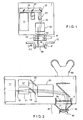
- FIG. 1 is a schematic representation of the individual components of an embodiment of a laser system according to the invention shown.
- the processing apparatus 1 comprises as a beam source 11 an fs laser beam source.
- the laser beam 15 is coupled out via mirrors and a beam splitter 57 onto a beam widening optical system 21.
- the expanded laser beam 15 ' is then directed to a beam focusing device 24 via a beam deflection device such as a scanner in the XY direction.
- a beam deflection device such as a scanner in the XY direction.
- This is displaceable in the Z-axis and thus allows the displacement of the focus point by displacement of the beam focusing along the arrow Z.
- a focusing optical system with variable focal length can be used to move the focus position controlled in the Z direction.
- the focused laser spot 16 is thus directed onto the material 90 to be processed, which is held in position by a fixing device 32.
- the material 90 is here a contact lens to be processed.
- the spot 16 can also be moved by moving the Fixing device 32 in the direction of XY 'and Z' are aligned on or in the material.
- the laser beam 15 generated by the beam source 11 is focused on the material 90.
- a focus diameter of a few micrometers can be achieved by focusing the laser beam 15 with a beam diameter of a few millimeters through optics with a few centimeters focal length.
- a focus diameter of three microns results when a laser beam of wavelength 1000 nm and a beam diameter of 10 mm is focused with a focal length of 50 mm.
- the laser beam 15 at the output of the beam source 11 has a smaller beam diameter than is necessary for optimal focusing.
- the beam diameter can be adapted to the requirements.
- a telescope in Galilei (diverging lens plus convergent lens) adjusted to infinity can be used as beam widening optics 21. This creates no intermediate focus, which could possibly lead to an optical breakthrough in air. Thus, the remaining laser energy is higher and the beam profile consistently good. Preference is given to the use of lens systems which lead to optimum imaging properties of the telescope. By adjusting the telescope and manufacturing fluctuations in the beam divergence of the beam source 11 can be compensated.
- the laser focus is scanned over or through the material.
- the laser focus or laser spot 16 is thus scanned three-dimensionally with micrometer accuracy.
- the expanded laser beam 15 ' is deflected perpendicular to the original beam direction by a deflector 23.
- the position of the focus 16 shifts to the focusing optics 24 perpendicular to the original beam direction.
- the focus can be moved in an area that is essentially flat and perpendicular to the laser beam direction (X / Y direction).
- the movement parallel to the beam direction (Z-direction) can take place on the one hand by moving the workpiece (see arrow Z ').
- the scanning algorithms are then preferably designed so that the workpiece must be moved only slowly and the fast scanning movements are performed by the deflection unit.
- the focusing optics can also be moved parallel to the direction of the laser beam (arrow Z) in order to reduce the focus in the Z direction.
- the second method is preferred because the patient generally can not be moved fast enough.
- the machined material 90 is fixed relative to the laser device in a fixing and adjusting device 32.
- the fixing device is adjusted vertically and parallel to the beam direction in order to place the pattern at the intended location in the material 90 can.
- One with the processing laser beam 15, 15 ' Collinear visible laser beam from a pilot laser 27 supports the adjustment.
- mirror or mirror pairs 22 are provided.
- the nature of the mirrors is preferably chosen so that the processing laser beam does not destroy them, the mirrors are highly reflective for the wavelength of the processing laser and are sufficiently reflective for the pilot laser.
- the coating is chosen so that the mirror does not significantly extend the laser pulse duration.
- at least one of the mirrors will be a so-called "chirped mirror" with which the dispersion of all optics present in the beam path can be compensated in order to achieve optimally short pulses in the machining focus.
- FIG. 2 another embodiment of the present laser processing apparatus is shown with surgical microscope.
- the structure corresponds essentially to the structure in FIG. 1 , Identical parts are identified by the same reference numerals.
- material 90 a human eye is provided here.
- this laser device will be described in detail, with which precise cuts in the cornea of the human eye can be introduced.
- a circular surface which follows the curvature of the cornea and is centered to the optical axis of the eye to be cut with fs laser pulses within the cornea.
- a circular segment-shaped edge section from the circular surface to the outside of the cornea creates a corneal flap (flap), which can be folded to the side after the laser cut.
- Such a flap is used to prepare for a LASIK operation in which laser ablation varies the thickness of the cornea to compensate for refractive errors of the eye. So far, this cut is carried out with a mechanical keratome, which requires a high degree of practice at the doctor and is fraught with risk.
- a refractive correction of the cornea can take place in the same operation by means of a further curved circular surface which, together with the first circular surface of the flap, encloses a lenticle which can be removed after opening the flap.
- the eye is pressed by a suction ring 32 to a contact glass 31, which is either flat, or preferably the curvature of the cornea is substantially adapted.
- the suction ring is firmly connected to the exit window of the laser device, which ensures a defined position of the cornea relative to the laser focus.
- the expanded femtosecond laser beam is focused with optics 24 in the cornea.
- a beam splitter which is highly reflective for the laser wavelength and transmitting for visible light, reflects the laser beam in the beam path of a surgical microscope, which is used for observation and centering of the eye.
- the focusing optics 24 forms a part of the microscope objective.
- a real intermediate image of the cornea can be generated, which can be combined with the stereo eyepiece 80 can look spatially.
- the beam deflection unit 23 deflects the expanded laser beam 15 perpendicular to its propagation direction.
- the laser focus can be directed to different points in the cornea.
- the depth of focus can be varied by displacing the focusing optics 24 along the optical axis or by adjusting the focal length of the focusing optics.
- the deflection unit travels circular paths.
- the circle radius is reduced from circular path to circular path and the repetition rate is adjusted so that a uniform spot spacing is maintained.
- the depth of focus is adjusted from orbit to orbit so that the cut follows the curvature of the cornea. If astigmatic corrections of the sight (cylinder correction) are to be introduced, the depth of focus during the circular path can be moved up and down twice, so that a lenticle with a cylindrical lens portion is formed.
- the focal depth is slowly shifted from the flap bottom to the outside of the cornea at a fixed radius, so that a cylinder jacket is created.
- the laser beam must be interrupted to leave a "hinge" on which the prepared flap is held. For this purpose, the decoupling of laser pulses from the beam source 11 is simply interrupted.
- the beam source 11 is a femtosecond beam source with the parameters described above, which is preferably directly diode pumped and thus simple and reliable.
- the emitted laser beam 15 is preferably expanded to a 1-2 cm beam diameter with a Galilean telescope. Collinear with the expanded laser beam 15, a visible laser beam from a pilot laser 27 is superimposed, which is then scanned and focused together with the processing laser beam.
- the beam splitter 57 is transparent to the femtosecond laser wavelength and reflective to the pilot beam for this purpose.
- a laser device as described is used for a variety of applications (for example for refractive corrections of vision) in which cuts or structural transformations are made within the transparent components of the eye (cornea, lens, vitreous) and on the non-transparent parts such as sclera, iris, ciliary body to be, suitable.
- the invention far surpasses existing technologies.
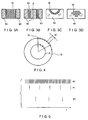
- FIG. 3 are shown in the sub-representations 3 a to d application examples of cutting geometries that can be realized with the laser system according to the invention. These applications are only examples - any other geometries can be realized.
- the cohesion of the material 90 is repealed (photodisruption). In general, this is associated with local evaporation of the material.
- the cavitation bubble hereinafter also called Spot 16
- Spot 16 the material structure permanently or for a lasting until at least the end of the processing period period.
- the use of a highly focused femtosecond laser thus provides the most precise localization of the laser effect. In the sharply limited focus volume, this destroys the material structure, while in closely adjacent areas (even less than a micrometer away) there is generally no change in the material. This results in a high processing precision while preserving adjacent material regions.
- a large number of individual spots that dissolve the material structure are placed next to each other.
- the distance between adjacent spots should be on the order of the spot diameter at the end of the procedure.
- a predetermined volume eg, a bore in the material
- spots 16 In FIG. 3b only the edge of the hole is covered with spots. It should be shown here a section through the material. The spots 16 should be arranged rotationally symmetrical about the dashed line Z. In this way, a core is produced in the center of the machined material 90. The drill core can then be removed as a coherent piece. The required number of laser pulses is thus significantly reduced, in particular in the case of large cross-sectional areas of the bore, in comparison to FIG. 3 a.
- FIG 3c an undercut in a transparent material 90 is shown. Since the radiation from the material 90 is not absorbed, contiguous pieces of material can be released from the material by placing spots on the cutting edge when it borders on the surface.
- the beam source of the laser device is therefore able according to the invention to emit laser pulses with a high repetition rate.
- FIG. 4 schematically a section of a possible scanning pattern is shown, in which the individual processed by individual laser pulses spots 16 along tracks are arranged, which can be traversed continuously by the scanner. In order to achieve a sufficiently large spot spacing at high repetition rates of the beam source 11, the focus becomes very fast in at least one of three scan dimensions emotional.
- the scanning algorithms are therefore preferably designed so that the spots are placed along paths that correspond to the natural movements of the deflection unit.
- the movement in the other two dimensions can then be relatively slow.
- the natural paths of the deflection unit may be, for example, circular paths that can run the deflection units with fixed circulating frequencies. This can be done for example by rotating optical elements in the deflection.
- the radius of the circular path and the depth of focus (Z-direction) are then the slowly variable scanning sizes. This variant is particularly suitable when rotationally symmetrical sectional figures have to be generated.
- the repetition rate of the laser can be used particularly effectively if the rotational frequency of the circular paths is chosen such that the full repetition rate of the beam source leads to the desired spot spacing d for the largest circular paths (B) to be traveled.
- the repetition rate of the source can be correspondingly reduced so that the optimum spot distance is again obtained.
- This adjustment of the repetition rate is readily possible with the described laser beam source.
- An adjustment of the rotational frequency to the repetition rate of the source may be technologically more difficult, especially if this is done continuously for each circular path (A, B). For a reduction of the processing time but an adjustment of the rotational frequency in a few steps to the smaller circular paths can be beneficial.
- the rotational frequency of the laser pulses in the oscillator 40 depends only on the resonator length and is predetermined for a particular beam source and is at resonator lengths of a few meters to 100 MHz.
- the pulses 41 are coupled into the amplifier and amplified. If a lower repetition rate is desired, the amplification of the pulses 43 takes place. A change in the repetition rate of the amplified laser pulses can thus be realized in an effortless manner.
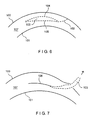
- FIG. 6 shows a sectional view of the human cornea 107 with front 100 and back 101.
- the lenticule 103 is formed by the two planar sections 104 and 105.
- a small lateral cut 102 which leads to the anterior corneal surface 100, allows the extraction of the lenticle 103. This extraction is in FIG. 7 shown.
- the remaining cavity collapses 106.
- FIG. 8 Visible is the boundary 111 of the lenticle 103, as well as leading to the corneal anterior surface sections 102. Along the line 110, the corneal front surface is severed and allows the extraction of the lens.
- FIG. 9 represents a further preferred form of the cutting guide.
- the lenticle was divided into two parts 123 and 124 by a section 122.
- a single extraction section 110 instead of a single extraction section 110 here are two extraction sections 120 and 121 appropriate.
- the lens part 123 is removed by the extraction section 120 and the lens part 124 by the extraction section 121.
- FIG. 10 represents a further development of the method.
- the lenticle bounded by the edge 111 is cut into many small fragments 132. These can now be aspirated using a cannula 133, which preferably has a diameter adapted to the fragment size. This process can be assisted by a flushing device via a second cannula 134, which is inserted into an opposite channel or also the same channel.
- the rinsing agent 136,135 is preferably isotonic saline, although other solutions may be used. This procedure realizes a minimal weakening of the cornea by this method of refractive laser surgery.
Landscapes
- Health & Medical Sciences (AREA)
- Optics & Photonics (AREA)
- Physics & Mathematics (AREA)
- Engineering & Computer Science (AREA)
- Ophthalmology & Optometry (AREA)
- Heart & Thoracic Surgery (AREA)
- Public Health (AREA)
- Veterinary Medicine (AREA)
- Surgery (AREA)
- Biomedical Technology (AREA)
- Nuclear Medicine, Radiotherapy & Molecular Imaging (AREA)
- Vascular Medicine (AREA)
- Life Sciences & Earth Sciences (AREA)
- Animal Behavior & Ethology (AREA)
- General Health & Medical Sciences (AREA)
- Plasma & Fusion (AREA)
- Mechanical Engineering (AREA)
- Laser Surgery Devices (AREA)
- Laser Beam Processing (AREA)
- Lasers (AREA)
- Electrical Discharge Machining, Electrochemical Machining, And Combined Machining (AREA)
- Removal Of Insulation Or Armoring From Wires Or Cables (AREA)
Abstract
Description
Die Erfindung betrifft eine Vorrichtung zur präzisen Bearbeitung von Material und Gewebe, insbesondere ein Lasergerät zur präzisen, mikrometergenauen Bearbeitung von organischem Material, bevorzugt einem Auge.The invention relates to a device for the precise processing of material and tissue, in particular a laser device for precise, micrometer accurate processing of organic material, preferably an eye.
In einem wertvollen Beitrag zum Stand der Technik wird in der Patentschrift
In einem weiteren wertvollen Beitrag zum Stand der Technik wird in der Patentschrift
In der
Die materialbearbeitende Wirkung des Lasers ist dabei auf den kleinen Raumbereich des Laserfokus (typischerweise einige µm3) beschränkt, in dem die Lichtintensität hoch genug ist, um die Schwelle des optischen Durchbruchs zu überschreiten. Lokalisiert auf dieses Fokusvolumen wird der Zusammenhalt des Materials zerstört und es entsteht eine Kavitationsblase. Wird der Laserfokus für jeden Laserpuls an eine neue Position gelenkt, können lineare, flächige oder dreidimensionale Schnittmuster generiert werden. Der Abstand benachbarter Kavitationsblasen muss am Ende der Bearbeitung etwa ihrem Durchmesser entsprechen, damit das Material entlang der Schnitte leicht mechanisch ablösbar ist.The material-processing effect of the laser is limited to the small spatial area of the laser focus (typically a few μm 3 ), in which the light intensity is high enough to exceed the threshold of the optical breakthrough. Localized to this focus volume, the cohesion of the material is destroyed and creates a cavitation bubble. If the laser focus is directed to a new position for each laser pulse, linear, area or three-dimensional patterns can be generated. The distance between adjacent cavitation bubbles must be approximately equal to their diameter at the end of processing, so that the material is easily mechanically removable along the cuts.
Die bestehenden Lasergeräte für die Materialbearbeitung mit Femtosekunden-Laserpulsen verwenden regenerative Verstärker mit Repetitionsraten bis 15 kHz, mit denen einzelne Pulse eines Femtosekundenoszillators verstärkt werden. Während der Oszillator selbst nur Pulsenergien im Nanojoule Bereich bereitstellt, können die Pulse mit einem regenerativen Verstärker bis zu einigen Millijoule Pulsenergie verstärkt werden. Während diese Laserquellen für Anwendungen mit hohen Abtragsraten pro Laserpuls geeignet sind, sind sie nicht optimal für die oben beschriebene Anwendung für Präzisionsschnitte.The existing laser equipment for material processing with femtosecond laser pulses use regenerative amplifiers with repetition rates up to 15 kHz, which amplify individual pulses of a femtosecond oscillator. While the oscillator itself provides only pulse energies in the nanjojoule range, the pulses can be amplified with a regenerative amplifier up to a few millijoules of pulse energy. While these laser sources are suitable for high erosion rate applications per laser pulse, they are not optimal for the precision cutting application described above.
Es ist bekannt, solche Laser für die refraktive Hornhautchirurgie zu verwenden. Übliche Pulsenergien betragen 5µJ bis 10µJ. Dadurch werden Kavitationsblasen erzeugt, deren Durchmesser 10µm bis 30µm beträgt. Durch diese Blasengröße wird eine Mikrorauhigkeit des erzeugten Schnittes in gleicher Größenordnung bewirkt. Bekannt ist andererseits, dass eine Mikrorauhigkeit in dieser Größenordnung nur unbefriedigende refraktive Ergebnisse gestattet.It is known to use such lasers for refractive corneal surgery. Usual pulse energies are 5μJ to 10μJ. As a result, cavitation bubbles are generated whose diameter is 10 μm to 30 μm. This bubble size causes micro roughness of the produced cut of the same order of magnitude. On the other hand, it is known that microroughness on this scale only allows unsatisfactory refractive results.
In der
In der
In
Aufgabe der vorliegenden Erfindung ist es daher, eine Vorrichtung zur präzisen Bearbeitung von Material bereitzustellen, mit der diese Nachteile des Standes der Technik überwunden werden.The object of the present invention is therefore to provide a device for the precise machining of material, with which these disadvantages of the prior art are overcome.
Diese Aufgabe wird durch die Vorrichtung nach dem unabhängigen Anspruch gelöst. Weitere vorteilhafte Ausgestaltungen sind in den abhängigen Ansprüchen angegeben.This object is achieved by the device according to the independent claim. Further advantageous embodiments are specified in the dependent claims.
Insbesondere wird die Aufgabe gelöst durch eine Vorrichtung zur präzisen Bearbeitung von Material, insbesondere organischem Material, wobei diese Vorrichtung im zu bearbeitenden Material Kavitationsblasen erzeugt, deren Durchmesser weniger als 10µm beträgt. Um dies zu erreichen, wird ein gepulster Laserstrahl mit einer Pulsenergie von weniger als 5µJ auf einen Fokusdurchmesser von wenigen µm fokussiert. Vorzugsweise beträgt der Fokusdurchmesser etwa 3µm und die Pulsenergie 1µJ. Weiter zeichnet sich die Vorrichtung dadurch aus, dass sie durch Verwendung einer Pulswiederholrate von mehr als 50 kHz eine sehr schnelle Bearbeitung gestattet. Dies ist insbesondere für die refraktive Hornhautchirurgie von großem Vorteil, weil damit eine Operationszeit von wenigen Sekunden bis ca. 1 Minute erreicht wird.
Die Aufgabe wird des Weiteren gelöst durch eine Vorrichtung zur präzisen Bearbeitung von Material, insbesondere organischem Material, umfassend ein gepulstes Lasersystem mit den oben beschriebenen Parametern als Strahlquelle, bei dem durch eine Strahleinrichtungen mit mindestens einem Mittel zur Strahlablenkung ein Arbeitsstrahl der Strahlquelle auf das Material applizierbar ist, wobei die Pulsaussendung mit der Strahlablenkung korreliert und wobei das Mittel zur Strahlablenkung Mittel zur Freigabe von Laserpulsen umfasst. Unter Freigabe wird dabei verstanden, dass der Laser für einen Laserimpuls freigegeben wird und der Laserimpuls ausgelöst wird, sobald der Laser entsprechend seiner maximalen Repetitionsrate erneut einen Laserimpuls abgeben kann. Unter Korrelation der Pulsaussendung mit der Strahlablenkung wird insbesondere verstanden, dass die Pulsaussendung erfolgen kann, wenn der Strahl auf einen bestimmten Punkt gelenkt wurde, die Pulsaussendung also in Abhängigkeit der Strahlablenkung angesteuert wird.In particular, the object is achieved by a device for the precise machining of material, in particular organic material, this device generates cavitation bubbles in the material to be machined, whose diameter is less than 10 microns. To achieve this, a pulsed laser beam with a pulse energy of less than 5μJ is focused to a focus diameter of a few μm. Preferably, the focus diameter is about 3μm and the pulse energy is 1μJ. Furthermore, the device is characterized in that it allows a very fast processing by using a pulse repetition rate of more than 50 kHz. This is of great advantage, in particular for refractive corneal surgery, because it allows an operating time of a few seconds to about 1 minute to be achieved.
The object is further achieved by a device for precise machining of material, in particular organic material, comprising a pulsed laser system with the parameters described above as a beam source, in which by a jet devices with at least one means for beam deflection, a working beam of the beam source can be applied to the material wherein the pulse emission correlates with the beam deflection, and wherein the means for beam deflection comprises means for releasing laser pulses. Under release is understood to mean that the laser is released for a laser pulse and the laser pulse is triggered as soon as the laser can deliver a laser pulse again according to its maximum repetition rate. Correlation of the pulse emission with the beam deflection is understood in particular to mean that the pulse emission can take place when the beam has been directed to a specific point, ie the pulse emission is activated as a function of the beam deflection.
In einer besonderen Ausgestaltung wird die vorgenannte Aufgabe gelöst durch eine Vorrichtung zur präzisen Bearbeitung von Material, insbesondere organischem Material, umfassend ein gepulstes Lasersystem als Strahlquelle, wobei die Energie der Strahlung etwa 100 nJ bis 10 µJ, vorzugsweise 500 nJ bis 5 µJ, beträgt. Die Repetitionsrate der Strahlung beträgt dabei vorzugsweise 50 khz bis 1 Mhz, besonders bevorzugt 100 khz bis 500 khz. Der Fokusdurchmesser der Strahlung beträgt dabei vorzugsweise etwa 500 nm bis 10 µm, besonders bevorzugt 3µm bis 5µm. Die Pulsdauer der Strahlung beträgt vorzugsweise etwa 100 fs bis 1 ps, besonders bevorzugt 200 fs bis 500 fs.In a particular embodiment, the above object is achieved by a device for precise machining of material, in particular organic material, comprising a pulsed laser system as a beam source, wherein the energy of the radiation about 100 nJ to 10 μJ, preferably 500 nJ to 5 μJ, is. The Repetitionsrate the radiation is preferably 50 khz to 1 Mhz, more preferably 100 khz to 500 khz. The focus diameter of the radiation is preferably about 500 nm to 10 .mu.m, more preferably 3 .mu.m to 5 .mu.m. The pulse duration of the radiation is preferably about 100 fs to 1 ps, more preferably 200 fs to 500 fs.
Die Mittel zur Strahlformung und/oder Strahlablenkung bzw. allgemeiner formuliert die Strahlformungs- und -ablenkungssysteme können diffraktive oder refraktive Mikrooptiken oder adaptive Optiken oder klassische optische Systeme umfassen. Mit diffraktiven oder refraktiven Elementen kann man dabei mehrere klassische bzw. konventionelle optische Elemente ersetzen.
Die genannte Vorrichtung zur präzisen Bearbeitung von Material wird vorzugsweise eingesetzt für die ophthalmologische Augenbehandlung, insbesondere zur Korrektur der Fehlsichtigkeit eines Auges. Die Vorrichtung kann zum Schneiden eines Flaps oder Lentikels in der Cornea zur Korrektur der Fehlsichtigkeit verwendet werden. Neben einem schneiden des Lentikels können mit der erfindungsgemäßen Vorrichtung refraktive Strukturen in der Cornea, beispielsweise in Form flächenmäßig nebeneinander gesetzter Spots oder einer Punktwolke, erzeugt werden.The beam shaping and / or beam deflection means or more generally the beam shaping and deflection systems may comprise diffractive or refractive micro-optics or adaptive optics or classical optical systems. With diffractive or refractive elements one can replace several classical or conventional optical elements.
Said device for the precise processing of material is preferably used for ophthalmological eye treatment, in particular for the correction of the refractive error of an eye. The device can be used to cut a flap or lenticle in the cornea to correct the ametropia. In addition to a cutting of the lenticle, refractive structures in the cornea, for example in the form of areally juxtaposed spots or a point cloud, can be generated with the device according to the invention.
Ebenso können unmittelbar Laserschüsse zur Erzeugung refraktiver Strukturen gesetzt werden Beispielsweise können in der Augenlinse kleine Bläschen durch verdampfen von Material bzw. Flüssigkeit erzeugt werden. Dazu sind sehr viele Laserschüsse mit vergleichsweise niedriger Energie erforderlich, wie sie mit der erfindungsgemäßen Vorrichtung bereit gestellt werden können.Likewise, laser shots can be set directly to produce refractive structures. For example, small bubbles can be produced in the eye lens by vaporization of material or liquid. For this purpose, very many laser shots with comparatively low energy are required, as can be provided with the device according to the invention.
Ebenso ist es möglich, mit der erfindungsgemäßen Vorrichtung gezielte Schnitte in das Gewebe, beispielsweise der Augenlinse, einzubringen und damit die Krümmbarkeit und Elastizität der Augenlinse zu verbessern, da sich die benachbarten Gewebeteile nun leichter gegeneinander verschieben lassen. Die Vorrichtung zur präzisen Bearbeitung von Material, insbesondere organischem Material, wird in dieser Ausgestaltung der Erfindung als Vorrichtung zur Behandlung der Presbyopie eingesetzt. Die Strahlformung erfolgt entweder konventionell oder mit diffraktiven bzw. refraktiven Mikrooptiken oder adaptiven Optiken. Die Strahlablenkung erfolgt vorzugsweise über Scansysteme.Likewise, it is possible to introduce targeted cuts into the tissue, for example the eye lens, with the device according to the invention, and thus to improve the curvability and elasticity of the eye lens, since the adjacent tissue parts can now be displaced more easily relative to one another. The device for the precise processing of material, in particular organic material, is used in this embodiment of the invention as a device for the treatment of presbyopia. The beam shaping takes place either conventionally or with diffractive or refractive micro-optics or adaptive optics. The beam deflection is preferably carried out via scanning systems.
Geeignete Laserstrahlquellen sind Oszillator-Verstärker-Anordnungen, wobei für den Verstärker insbesondere regenerative Verstärker, Chirped-Pulse-Verstärker (CPA) oder Multipass-Verstärker geeignet sind.Suitable laser beam sources are oscillator-amplifier arrangements, with regenerative amplifiers, chirped-pulse amplifiers (CPA) or multipass amplifiers being particularly suitable for the amplifier.
Hinsichtlich der Bauform des modengekoppelten Oszillators sind insbesondere Scheibenlaseroszillatoren, Faserlaseroszillatoren, aber auch Stablaseroszillatoren geeignet. Hinsichtlich der Bauform des Verstärkers sind insbesondere Scheibenlaserverstärker, Faserlaserverstärker, aber auch Stablaserverstärker geeignet. Als Pumpquelle für die Lasermedien sind Halbleiter-Laserdioden aufgrund ihrer langen Lebensdauer, Zuverlässigkeit, Regelbarkeit und ihrer vergleichsweise geringen Herstellungskosten besonders vorzuziehen.With regard to the design of the mode-locked oscillator, in particular disk laser oscillators, fiber laser oscillators, but also bar laser oscillators are suitable. With regard to the design of the amplifier, in particular disk laser amplifiers, fiber laser amplifiers, but also laser beam amplifiers are suitable. As a pumping source for the laser media, semiconductor laser diodes are particularly preferable because of their long life, reliability, controllability and their comparatively low manufacturing cost.
Bevorzugte Lasermedien in obigen Laserstrahlquellen sind dotierte Festkörpermaterialien, insbesondere Kristalle und Gläser. Beispielsweise sind dies YAG, Wolframate, Saphir und Fluoridgläser.Preferred laser media in the above laser beam sources are doped solid state materials, especially crystals and glasses. For example, these are YAG, tungstates, sapphire and fluoride glasses.
Diese Wirtsmaterialien können bevorzugt mit Neodym, Erbium, Titan, Chrom, Lithium oder Ytterbium dotiert werden. Alle diese Materialien zeichnen sich durch eine spektral breitbandige Laseremission im Spektralbereich von 600 nm bis 2000 nm aus und umfassen damit den für die refraktive Hornhautchirurgie besonders geeigneten Spektralbereich zwischen 800 nm und 1200 nm.These host materials may preferably be doped with neodymium, erbium, titanium, chromium, lithium or ytterbium. All of these materials are characterized by a spectrally broadband laser emission in the spectral range from 600 nm to 2000 nm and thus include the spectral range between 800 nm and 1200 nm which is particularly suitable for refractive corneal surgery.
Die große spektrale Bandbreite der Laseremission der oben genannten Materialien unterstützt eine ultrakurze Laserpulsdauer zwischen 50 fs und 1 ps. Dabei ist es nicht erforderlich, dass der Laser selbst Pulse dieser Pulsdauer emittiert, dass aber die bevorzugte Impulsdauer von etwa 300 fs im zu bearbeitenden Werkstück bzw. auf seiner Oberfläche erreicht wird. Zu diesem Zweck umfasst die Vorrichtung ein optisches Modul welches dazu dient, die spektrale Phasenfunktion der Laserpulse geeignet zu beeinflussen. Insbesondere erzeugt dieses optische Modul einen linearen Pre-Chirp, dessen Betrag dem linearen Chirp des optischen Systems angepasst ist. Diese optische Modul kann bereits in einer Laserstrahlquelle geeignet integriert sein, insbesondere kann es mit dem Pulskompressor einer CPA-Laserstrahlquelle kombiniert oder mit diesem identisch sein.The large spectral bandwidth of the laser emission of the above materials supports an ultra-short laser pulse duration between 50 fs and 1 ps. It is not necessary that the laser itself emits pulses of this pulse duration, but that the preferred pulse duration of about 300 fs is achieved in the workpiece to be machined or on its surface. For this purpose, the device comprises an optical module which serves to appropriately influence the spectral phase function of the laser pulses. In particular, this optical module generates a linear pre-chirp, the amount of which is adapted to the linear chirp of the optical system. This optical module may already be suitably integrated in a laser beam source, in particular it may be combined with or identical to the pulse compressor of a CPA laser beam source.
Das bevorzugt mit Mikrometergenauigkeit zu bearbeitende Material kann Material mit Strukturen im Mikrometerbereich, Gitter, Kontaktlinsen, Kunststoffe, Intraokkularlinsen (IOL), Halbleiterwafer, mikrooptische Elemente etc. umfassen. Besonders bevorzugt ist organisches Material, wie beispielsweise Gewebe, besonders bevorzugt das Gewebe des menschlichen Auges.The micron precision material to be machined may include micron sized material, grids, contact lenses, plastics, intraocular lenses (IOL), semiconductor wafers, micro-optical elements, etc. Particularly preferred is organic material, such as tissue, most preferably the tissue of the human eye.
Das gepulste Lasersystem ist eine Anordnung einer Laserstrahlquelle zur Erzeugung von fs-Pulsen und entsprechenden optischen Vorrichtungen, insbesondere Spiegel, Linsen, etc.The pulsed laser system is an arrangement of a laser beam source for generating fs pulses and corresponding optical devices, in particular mirrors, lenses, etc.
In einer Ausgestaltung der erfindungsgemäßen Vorrichtung ist vorgesehen, dass das Mittel zur Strahlablenkung im Scan-Modus betrieben werden. Der Arbeitsstrahl der Strahlquelle kann dabei auf in einer Dimension periodisch wiederkehrenden Bahnen abgelenkt werden, sodass beispielsweise kreisförmige Bahnen unterschiedlicher Durchmesser oder spiralförmige Bahnen erzeugt werden können. Die Bahnen des Arbeitsstrahles können durch eine rotierende oder in anderer Weise auf einer Bahn gehaltenen Vorrichtung, beispielsweise durch einen Spiegel, eine Linse, ein Gitter oder dergleichen, erzeugt werden. Die Mittel zur Strahlablenkung können Scanner, z.B. mechanische Scanner, umfassen, die auf vorgegebenen Bahnen bewegbar gelagert sind. Die vorliegende Erfindung nutzt schnelle Ablenksysteme, die den Laser auf den natürlichen Bahnen des Ablenksystems ablenkt, also z.B. auf Kreisbahnen oder Spiralbahnen bei rotierenden Ablenksystemen. Anstatt einzelne Positionen anzufahren und dort einen Laserimpuls auszulösen, sobald die vorgegebene Position erreicht ist und das Ablenksystem wieder ruht, wird die Bahn des Ablenksystems ohne Stops durchlaufen und die Pulse werden durch eine vorgewählte, über die Bahngeschwindigkeit der Fokusbewegung vorgegebene Repetitionsrate beginnend zu einem definierten Zeitpunkt abgegeben.
Sobald also die Fokusposition einen bestimmten Punkt erreicht hat, wird der Laser freigegeben und damit Laserpulse auf das Bearbeitungsgebiet gesendet. Dies führt zu einer Spur von Wirkvolumina, mithin durch den Laserfokus während der kurzen Pulsdauer modifizierte Stellen im Material, entlang einer im wesentlichen vordefinierten Bahn, die insbesondere dadurch ausgezeichnet ist, dass benachbarte Wirkvolumina in gleichbleibendem, vordefiniertem Abstand, beispielsweise in der Größenordnung des Durchmessers der Kavitationsblasen, platziert werden. Durch leichte Modifikation der natürlichen Bahn des Ablenksystems, z.B. durch eine leichte Reduktion des Kreisbahnradius, beispielsweise um den Betrag des Abstandes benachbarter Wirkvolumina, können weitere Spuren geschrieben werden, die sich zu einer Schnittfläche ergänzen. Beispielsweise können hier konzentrische Bahnen oder spiralförmige Bahnen oder dergleichen erzeugt werden. Bei Verwendung eines Ablenkspiegels kann dies beispielsweise durch eine Veränderung der Neigung bei gleichbleibender Rotation des Spiegels geschehen. Ziel ist es, die gewünschte Schnittfläche mit einem gleichmäßigen Raster von Wirkvolumina bzw. Laserfoki zu überdecken. Die natürlichen Bahnen des Ablenksystems können aufgrund der hohen Repetitionsrate des Lasersystems sehr schnell mit definiertem zeitlichem Ablauf durchfahren werden. Die Anpassung der zeitlichen Abfolge der Laserpulse führt dann zur gewünschten Überdeckung der Schnittfläche mit Laserschüssen.In one embodiment of the device according to the invention it is provided that the means for beam deflection are operated in the scan mode. The working beam of the beam source can be deflected on in one dimension periodically recurring tracks, so that for example circular paths of different diameters or spiral tracks can be generated. The webs of the working beam can travel through a rotating or otherwise on a path held device, for example by a mirror, a lens, a grid or the like, are generated. The means for beam deflection may include scanners, such as mechanical scanners, which are movably mounted on predetermined paths. The present invention utilizes fast deflection systems which deflect the laser on the natural paths of the deflection system, eg on circular paths or spiral tracks in rotating deflection systems. Instead of approaching individual positions and triggering a laser pulse there, as soon as the predetermined position is reached and the deflection system rests again, the path of the deflection system is traversed without stops and the pulses are passed through a preselected repetition rate predetermined by the path velocity of the focus movement starting at a defined time issued.
As soon as the focus position has reached a certain point, the laser is released and thus laser pulses are sent to the processing area. This leads to a trace of effective volumes, thus places modified in the material by the laser focus during the short pulse duration, along a substantially predefined path, which is particularly distinguished by the fact that adjacent effective volumes have a constant, predefined distance, for example of the order of magnitude of the diameter Cavitation bubbles, are placed. By slightly modifying the natural orbit of the deflection system, for example by slightly reducing the orbit radius, for example by the amount of the spacing of adjacent effective volumes, further tracks can be written that complement each other to form a cut surface. For example, concentric or spiral tracks or the like can be produced here. When using a deflecting mirror, this can be done for example by changing the inclination with constant rotation of the mirror. The aim is to cover the desired cut surface with a uniform grid of effective volumes or laser foci. Due to the high repetition rate of the laser system, the natural paths of the deflection system can be traversed very quickly with a defined time sequence. The adaptation of the time sequence of the laser pulses then leads to the desired coverage of the cut surface with laser shots.
Bei einem weiteren Ausführungsbeispiel der vorliegenden Erfindung sind weiter Strahleinrichtungen zur Strahlformung und/oder Strahlführung und/oder Strahlablenkung und/oder Strahlfokusierung vorgesehen. Durch diese Strahleinrichtungen kann der Strahl genau so auf das zu bearbeitende Material gelenkt und geleitet werden, wie es die geplante Anwendung erfordert. Die hier auf einen Fokusdurchmesser in der Größenordnung von 3 µm fokussierten ultrakurzen Laserpulse können insbesondere aufgrund ihrer geringen Pulsenergie von etwa 1µJ in einer kleinen, präzisen Kavitationsblase den Materialzusammenhalt lösen und/oder strukturelle Veränderungen im Material hervorrufen ohne benachbarte Gebiete im Material thermisch, akustisch oder mechanisch zu belasten. Für makroskopische Schnitte und Strukturen im Zentimetermaßstab wird der Laserfokus dreidimensional durch das zu bearbeitende Material gescannt. Der Anwendungsfall bestimmt, wie Strahlquelle,In a further exemplary embodiment of the present invention, further jet devices are provided for beam shaping and / or beam guidance and / or beam deflection and / or beam focusing. By means of these jet devices, the jet can be directed and directed to the material to be processed exactly as required by the intended application. The focused on a focus diameter of the order of 3 microns ultra-short laser pulses, especially due to their low pulse energy of about 1μJ in a small, precise Kavitationsblase solve the material cohesion and / or cause structural changes in the material without adjacent areas in the material thermally, acoustically or mechanically to charge. For macroscopic sections and structures on a centimeter scale, the laser focus is scanned three-dimensionally through the material to be processed. The application determines, like beam source,
Strahlführung und -formung, Scanner, Scanalgorithmus und Fokussieroptik aufeinander abgestimmt werden, um eine hohe Bearbeitungsgeschwindigkeit bei gleichzeitig hoher Präzision zu erreichen.Beam guidance and shaping, scanner, scanning algorithm and focusing optics are coordinated to achieve a high processing speed with high precision.
Die Strahlformung geschieht dabei bevorzugt mittels eines Teleskops (bevorzugt Galilei-Teleskop mit Sammel- und Streulinse), das den Strahldruchmesser so aufweitet, dass der Laser auf einen entsprechend kleinen Fokus fokussiert werden kann. Bevorzugt wird ein Linsensystem verwendet, das die Abbildungsfehler des Teleskops weitgehend minimiert.The beam shaping is preferably done by means of a telescope (preferably Galileo telescope with collecting and scattering lens), which expands the beam diameter so that the laser can be focused on a correspondingly small focus. Preferably, a lens system is used, which minimizes the aberrations of the telescope largely.
Die Strahlführung erfolgt bevorzugt durch Spiegel oder Spiegelpaare, mit denen der Strahl in die einzelnen Subkomponenten justiert werden kann.The beam guidance is preferably carried out by mirrors or mirror pairs with which the beam can be adjusted into the individual subcomponents.
Die Strahlablenkung können konventionelle Scanner bzw. mechanische Laserstrahl-Ablenksysteme wie Galvanometerspiegel im Close-Loop-Betrieb, etc. sein. Bevorzugt jedoch sind mechanische Scanner, die vorgegebene Bahnen (z.B. Kreisbahnen) abfahren und durch Triggerung der Strahlquelle an den vorgesehenen Positionen dadurch Laserpulse ausgelöst werden. So kann auf einem großen Bereich der Schnittfläche mit voller Repetitionsrate bei relativ langsamen Scannerbewegungen gearbeitet werden.
Die Strahlfokussiemngseinrichtung dient dazu, im Fokus des Strahls auf oder innerhalb des Materials den Zusammenhalt des Materials aufzuheben (Photodisruption). Im Allgemeinen geht das mit einer lokalen Verdampfung des Materials einher. Bevorzugt wird der Laser hierfür auf einen Durchmesser im Mikrometerbereich fokussiert. Dies liegt nahe am Beugungslimit von Licht im sichtbaren bzw. nahen Infrarotbereich. Die Fokussieroptik weist daher bevorzugt eine hohe numerische Apertur und damit eine kurze Brennweite und eine große optische Öffnung (aufgeweiteter Laserstrahl Durchmesser) aus. Bevorzugt wird der von der Laserquelle ausgehende Strahl vor der Fokussierung auf das Material bzw. Gewebe im Durchmesser aufgeweitet. Die Systeme zur Strahlführung, -ablenkung und -fokussierung sind daher bevorzugt für einen großen Stahldurchmesser ausgelegt.The beam deflection can be conventional scanners or mechanical laser beam deflection systems such as galvanometer mirrors in close-loop operation, etc. Preferably, however, are mechanical scanners, the predetermined paths (eg circular paths) depart and by triggering the beam source at the intended positions thereby laser pulses are triggered. For example, you can work on a large area of the cut surface with full repetition rate with relatively slow scanner movements.
The Strahlfokussiemngseinrichtung serves to cancel the cohesion of the material in the focus of the beam on or within the material (photodisruption). In general, this is associated with local evaporation of the material. For this purpose, the laser is preferably focused to a diameter in the micrometer range. This is close to the diffraction limit of light in the visible or near infrared range. The focusing optics therefore preferably have a high numerical aperture and thus a short focal length and a large optical aperture (expanded laser beam diameter). Preferably, the beam emanating from the laser source is widened in diameter before focusing on the material or tissue. The systems for beam guidance, deflection and focusing are therefore preferably designed for a large steel diameter.
Laserquelle, Stahlablenkung (Scanner) und Fokussieroptik sind so aufeinander abgestimmt, dass präzise und schnelle Schnittführung im Wege der Fotodisruption ermöglicht wird. Dabei werden Laserspots mit einem Fokusdurchmesser von einigen 100 nm bis einigen µm mit einem Spotabstand in der Größenordnung des Kavitationsblasendurchmessers im Material platziert.Laser source, steel deflection (scanner) and focusing optics are coordinated so that precise and fast cutting is possible by means of photodisruption. In this case, laser spots are placed with a focus diameter of a few 100 nm to a few microns with a spot spacing of the order of Kavitationsblasendurchmessers in the material.
In einer besonders bevorzugten Ausführungsform sind die Strahleinrichtungen, insbesondere die Ablenkeinrichtungen, programmierbar. Durch die Abstimmbarkeit der einzelnen Strahleinrichtungen aufeinander und die Steuerung durch entsprechende Programme kann das System der Strahleinrichtungen zusammen mit dem gepulsten Lasersystem genau auf das Material und die Schnittanforderung eingestellt werden, für die es eingesetzt werden soll. So kann in Abhängigkeit der Transparenz und Brechkraft des zu bearbeitenden Materials sowie der Anforderung an Schnittgeometrie und Operationsdauer das Set an Parametern durch das Programm vorgewählt und abgestimmt werden.In a particularly preferred embodiment, the jet devices, in particular the deflection devices, are programmable. The tunability of the individual jet devices to each other and the control by appropriate programs, the system of the jet devices can be adjusted together with the pulsed laser system exactly on the material and the cutting request for which it is to be used. Thus, depending on the transparency and refractive power of the material to be processed as well as the requirement for cutting geometry and Operation duration, the set of parameters to be selected and tuned by the program.
In einer weiteren bevorzugten Ausführungsform der vorliegenden Erfindung sind weiter Haltevorrichtungen zur Positionierung und/oder Fixierung des zu bearbeitenden Materials vorgesehen. Durch diese Haltevorrichtungen wird sichergestellt, dass die mikrometergenauen Strukturen, die durch den erfindungsgemäßen Laser hergestellt werden können, nicht durch unkontrollierbare Bewegungen des zu bearbeitenden Materials, insbesondere des menschlichen Auges, beeinträchtigt werden.In a further preferred embodiment of the present invention further holding devices for positioning and / or fixing of the material to be processed are provided. These holding devices ensure that the micrometer-accurate structures which can be produced by the laser according to the invention are not impaired by uncontrollable movements of the material to be processed, in particular of the human eye.
Eine solche Fixier- und Positioniervorrichtung kann eine einfache Klemmvorrichtung für ein Werkstück sein, das bevorzugt mit Mehrachsen-Justagemöglichkeiten zur Bewegung und Verkippung des Werkstücks zur optimalen Justage ausgestattet ist. Fixiereinrichtungen für die medizinische Anwendungen an Organen wie zum Beispiel dem Auge müssen außerdem den jeweiligen biologischen Gegebenheiten angepasst sein. Die Fixierung des menschlichen Auges kann zum Beispiel mit Hilfe eines speziellen Adapters und eines Vakuum-Saugringes erfolgen.Such a fixing and positioning device may be a simple clamping device for a workpiece, which is preferably equipped with multi-axis adjustment options for movement and tilting of the workpiece for optimal adjustment. Fixing devices for medical applications on organs such as the eye must also be adapted to the respective biological conditions. The fixation of the human eye can be done for example with the help of a special adapter and a vacuum suction ring.
Mit den beschriebenen hohen Repetitionsraten kann in Abstimmung mit den beschriebenen Pulsenergien geringen Betrages und der Ablenkeinrichtungen die Laserwirkung für die Photodisruption präzise lokalisiert werden. Hierdurch wird in einem scharf begrenzten Fokusvolumen das Materialgefüge zerstört, in dicht benachbarten Bereichen (von weniger als ein Mikrometer entfernt) findet im Allgemeinen keine Veränderung des Materials statt. Daraus ergibt sich eine hohe Bearbeitungspräzision (Mikrometergenauigkeit) bei Schonung benachbarter Materialregionen. Thermische und mechanische Beanspruchung der nicht bearbeiteten Regionen sind deutlich geringer als bei anderen Bearbeitungsmethoden.With the described high repetition rates, the laser effect for the photodisruption can be precisely located in coordination with the described low-energy pulse energies and the deflection devices. As a result, the material structure is destroyed in a sharply limited focus volume, in closely adjacent areas (less than a micrometer away) there is generally no change in the material. This results in a high machining precision (micrometer accuracy) while preserving adjacent material regions. Thermal and mechanical stress on unprocessed regions is significantly lower than with other processing methods.
Bei einer weiteren bevorzugten Ausführungsform der erfindungsgemäßen Vorrichtung ist durch die Strahleneinrichtung, insbesondere die Ablenkeinrichtung, ein Arbeitsstrahl der Strahlquelle in geometrisch vorbestimmbarer Form in zeitlich vorbestimmbarem Verlauf auf das Material applizierbar. Durch das Zusammenspiel der einzelnen Komponenten ist so möglich, Schnitte und Strukturierungen zu erzeugen. Zur Erzeugung eines Spots, in dem das Materialgefüge aufgelöst wurde, genügt im Allgemeinen ein Laserpuls mit definiertem Pulsparametern (Pulsenergie, Pulsdauer, Fokus). Für Schnitte und Strukturierung ist eine Vielzahl solcher Spots dicht nebeneinander zu plazieren. Der Abstand benachbarter Spots sollte am Ende der Prozedur in der Größenordnung der Kavitationsblasen liegen. Dafür kann der Laserfokus scannend über bzw. durch das Material bewegt werden. Der Laserfokus folgt in idealer Weise 3-dimensional mit Mikrometergenauigkeit einer vorgegebenen geometrischen Bahn. So ist es beispielsweise möglich, einen Schnitt in dem zu bearbeitenden Material dadurch zu erzeugen, dass eine beliebige Fläche, zum Beispiel eine Rechteckfläche benachbarter Mikrometerspots in dem Gewebe nacheinander scannend angesteuert wird. Dadurch wird genau in dieser Ebene der Materialzusammenhalt aufgelöst und dadurch ein "Schnitt" im Gewebe erzeugt. Genauso ist es möglich, den Laserfokus durch Kreisbewegungen des Scanners in einer Kreisbahn auf das zu bearbeitende Material zu applizieren. Durch eine sich anschließende helixförmige Führung des Bearbeitungsstrahls kann so beispielsweise eine Zylinderfläche aus dem Material herausgeschnitten werden. Da die Photodisruption bevorzugt in einem sehr engen Bereich stattfindet, kann der Laserstrahl auch im Gewebe wirken, ohne dass das vom Laserstrahl außerhalb des Fokus durchdrungene Material beschädigt wird. Auf diese Weise sind beliebige geometrische Bahnen und damit Formen durch Photodisruption in dem Material herausschneidbar.In a further preferred embodiment of the device according to the invention by the beam means, in particular the deflecting device, a working beam of the beam source in geometrically predeterminable form in time predeterminable course on the material can be applied. The interaction of the individual components makes it possible to create cuts and structuring. To generate a spot in which the material structure has been resolved, a laser pulse with defined pulse parameters (pulse energy, pulse duration, focus) is generally sufficient. For cuts and structuring, a large number of such spots must be placed close to each other. The distance between adjacent spots should be around the size of the cavitation bubbles at the end of the procedure. For this, the laser focus can be scanned over or through the material. The laser focus ideally follows 3-dimensional with micrometer accuracy of a given geometric trajectory. For example, it is possible to create a cut in the material to be processed by having any surface, for example a rectangular area, of adjacent micrometer spots in the tissue in succession scanned is driven. As a result, the material cohesion is resolved precisely in this level, thereby creating a "cut" in the tissue. It is equally possible to apply the laser focus by circular movements of the scanner in a circular path on the material to be processed. By a subsequent helical guidance of the processing beam, for example, a cylindrical surface can be cut out of the material. Since the photodisruption preferably takes place in a very narrow range, the laser beam can also act in the tissue without damaging the material penetrated by the laser beam out of focus. In this way, any geometric paths and thus shapes can be cut out by photodisruption in the material.
Bei der refraktiven Hornhautchirurgie kann mit der erfindungsgemäßen Vorrichtung eine spezielle Schnittführung realisiert werden. Dabei wird kein traditioneller Flap präpariert, sondern das zuvor mit der erfindungsgemäßen Vorrichtung in der Cornea präparierte Lentikel über einen oder mehrere begrenzte seitliche Schnitte, welche ebenfalls mit der erfindungsgemäßen Vorrichtung erzeugt werden, am Umfang extrahiert. Zu diesem Zweck kann es vorteilhaft sein, dass Lentikel zuvor durch einen oder mehrere Schnitte mit der erfindungsgemäßen Vorrichtung zu zerteilen. Insbesondere ist eine Zerteilung derart sinnvoll, dass anschließend eine Entfernung der Teile mittels Absaugung mit einer Saug-Spül-Kanüle erfolgen kann.In refractive corneal surgery, a special cutting guide can be realized with the device according to the invention. In this case, no traditional flap is prepared, but the previously prepared with the device according to the invention in the cornea lenticles via one or more limited lateral sections, which are also generated with the device according to the invention, extracted at the periphery. For this purpose, it may be advantageous to divide the lenticle beforehand by one or more cuts with the device according to the invention. In particular, a fragmentation is so useful that then a removal of the parts can be done by suction with a suction-flushing cannula.
Beim bevorzugten Ausführungsbeispiel der vorliegenden Erfindung ist eine Vorrichtung vorgesehen, bei der der gepulste Arbeitsstrahl durch die Strahlablenkungseinrichtung auf das Material applizierbar ist und währenddessen die Repetitionsrate der Pulse des Arbeitsstrahles modifizierbar ist. Durch das Vorsehen einer Einrichtung zur Modifizierung der Repetitionsrate bei gleichzeitiger Strahlführung des Arbeitsstrahles über das zu bearbeitende Material kann auf diese Weise elegant ein gleichmäßiges Spotmuster auf dem zu behandelnden Material erzeugt werden, auch wenn der Strahl unter verschiedenen Winkeln bzw. verschieden schnell durch die Ablenkeinrichtung auf das zu bearbeitende Material gerichtet wird. Ein besonders augenfälliger Vorteil wird beispielsweise dann erreicht, wenn die Ablenkeinrichtung den Strahl in Kreisbahnen auf das zu bearbeitende Material lenkt und diese Kreisbahnen mit einer speziellen Umlauffrequenz der Ablenkeinrichtung, insbesondere beispielsweise der Ablenkspiegel, erzeugt wird. Wird bei einer Umlauffrequenz von beispielsweise 50Hz der Laserstrahl auf einer Kreisbahn von 1cm Durchmesser bei einer Repetitionsrate von 300kHz geführt, dann werden auf jeder Kreisbahn pro Umlauf gleichmäßig verteilt 60000 Spots gesetzt. Wenn der Strahl dann auf einem Kreis von nur 0,5cm Durchmesser mit derselben Frequenz der Ablenkeinrichtung gerührt wird, kann durch Erniedrigung der Repetitionsrate des gepulsten Arbeitsstrahles der gleiche Abstand der einzelnen Spots voneinander auf dem zu bearbeitenden Material erzeugt werden, wie bei der Strahlführung auf der größeren Kreisbahn. Durch eine entsprechende Modifikation der Repetitionsrate in Abhängigkeit der durch die Ablenkeinrichtung abgefahrenen Geometrie lassen sich so beliebige geometrische Muster mit einem im Wesentlichen gleich bleibenden Spotabstand auf dem zu bearbeitenden Material erzeugen. Beispielsweise können Spiralen abgefahren werden, bei denen von außen nach innen bei gleichbleibender Umlauffrequenz der Ablenkeinrichtung die Repetitionsrate immer weiter abnimmt. Daneben sind auch beliebige andere geometrische Formen denkbar. Ist eine konstante Beabstandung der einzelnen Spots auf dem Material gerade nicht beabsichtigt, sondern soll vielmehr in einem speziellen Bereich eine höhere Spotdichte und in einem weiteren Bereich eine niedrigere Spotdichte erreicht werden, so kann dies ebenfalls durch Kombination der gewählten Parameter für die Repetitionsrate des Arbeitsstrahles und die Frequenz bzw. den örtlichen Verlauf der Ablenkeinrichtung erzeugt werden. So ist es bevorzugt auch möglich, graduell unterschiedliche Bereiche mit verschiedener Fokusdichte zu erzeugen. Beispielsweise kann bei einem Kreis das Zentrum einen sehr niedrigen Fokusabstand aufweisen während der Fokusabstand zum Rand hin immer größer wird.In the preferred embodiment of the present invention, a device is provided in which the pulsed working beam can be applied to the material by the beam deflection device and during which the repetition rate of the pulses of the working beam can be modified. By providing a means for modifying the repetition rate with simultaneous beam guidance of the working beam over the material to be processed in this way can be elegantly generated a uniform spot pattern on the material to be treated, even if the beam at different angles or at different speeds through the deflection on the material to be processed is directed. A particularly obvious advantage is achieved, for example, when the deflection device directs the beam in circular paths onto the material to be processed and these circular paths are generated at a specific rotational frequency of the deflection device, in particular for example the deflection mirror. If, at a rotational frequency of, for example, 50 Hz, the laser beam is guided on a circular path of 1 cm in diameter at a repetition rate of 300 kHz, then 60000 spots are set uniformly distributed on each circular path per revolution. If the beam is then agitated on a circle of only 0.5 cm diameter with the same frequency of the deflector, by lowering the repetition rate of the pulsed working beam, the same distance of the individual spots from each other on the material to be processed can be generated as in the beam guide on the larger circular path. By a corresponding modification of the repetition rate as a function of the geometry traveled by the deflecting device, it is thus possible to generate any desired geometric patterns with a substantially constant spot spacing on the material to be processed. For example, spirals can be traversed, in which from outside to inside with constant rotational frequency of the deflector, the repetition rate continues to decrease. In addition, any other geometric shapes are conceivable. If a constant spacing of the individual spots on the material is not intended, but rather a higher spot density should be achieved in one specific area and a lower spot density in another area, this can likewise be achieved by combining the selected parameters for the repetition rate of the working beam and the frequency or the local course of the deflection are generated. Thus, it is preferably also possible to produce gradually different regions with different focus density. For example, in a circle, the center may have a very low focus distance while the focal distance towards the edge becomes larger and larger.
Ein Verfahren zur Applikation von fs-Pulsen einer Laserstrahlquelle mit oben genannten Eigenschaften, insbesondere hoher Repetitionsrate und geringer Pulsenergie, auf ein Material, insbesondere ein organisches Material, insbesondere das menschliche Auge, bei dem im Fokus des Laserstrahls das Material mittels Photodisruption bearbeitet wird bzw. dessen Zusammenhalt aufgelöst wird, ist ebenfalls möglich.A method for applying fs pulses of a laser beam source with the above properties, in particular high repetition rate and low pulse energy, to a material, in particular an organic material, in particular the human eye, in which the material is processed by means of photodisruption in the focus of the laser beam or its cohesion is resolved is also possible.
Bei einem besonders bevorzugten Verfahren wird der gepulste Laserstrahl mittels einer Ablenkeinrichtung auf das zu bearbeitende Material gelenkt und in Abhängigkeit des hierdurch auf dem Material erzeugten Spotmusters die Repetitionsrate der Pulse des Laserstrahls modifiziert. Auf diese Weise kann jedes beliebige Spotmuster und insbesondere jede beliebige Beabstandung der einzelnen Spots voneinander in der gewünschten Geometrie auf dem zu bearbeitenden Material erzeugt werden. Besonders bevorzugt werden die Spotmuster so auf dem zu bearbeitenden Material verteilt, dass die Kavitationsblase jedes einzelnen Spots, die durch Photodisruption entsteht, genau benachbart zu der Kavitationsblase des nächsten Spots gesetzt wird. Auf diese Weise entsteht dann ein gewünschtes Schnittmuster direkt benachbarter Kavitationsblasen. Für spezielle Anwendungsfälle kann es auch gewünscht sein, die Spots noch enger zu setzen. Dies ist beispielsweise dann empfehlenswert, wenn das zu bearbeitende Material sich nach einer gewissen Zeit wieder erneuert und die Ablösung des Materials für eine spezielle Zeit sichergestellt werden soll, bevor beispielsweise der Bohrkern oder ein sonst herausgeschnittenes Stück des zu bearbeitenden Materials entfernt werden kann. Ebenso ist es denkbar, dass die Spots zuerst mit einer größeren Beabstandung gesetzt werden, um in einem folgenden Schritt die Lücken zwischen den Spots zu füllen und dadurch ein gewünschtes Muster von Kavitationsblasen zu bilden.In a particularly preferred method, the pulsed laser beam is deflected by means of a deflecting device onto the material to be processed, and the repetition rate of the pulses of the laser beam is modified as a function of the spot pattern produced thereby on the material. In this way, any desired spot pattern and in particular any spacing of the individual spots from each other in the desired geometry on the material to be processed can be generated. Particularly preferably, the spot patterns are distributed on the material to be processed such that the cavitation bubble of each individual spot, which results from photodisruption, is placed exactly adjacent to the cavitation bubble of the next spot. In this way, a desired pattern of directly adjacent cavitation bubbles is created. For special applications, it may also be desirable to set the spots even closer. This is recommended, for example, when the material to be processed is renewed after a certain time and the separation of the material for a specific time is to be ensured before, for example, the core or an otherwise cut out piece of material to be processed can be removed. It is also conceivable that the spots are first set at a greater spacing in order to fill the gaps between the spots in a subsequent step and thereby form a desired pattern of cavitation bubbles.
Die erfindungsgemäße Vorrichtung kann verwendet werden zur refraktiven Chirurgie durch Bearbeitung der Cornea oder der Linse des Auges.The device according to the invention can be used for refractive surgery by processing the cornea or the lens of the eye.
Im Folgenden sollen weitere vorteilhafte Ausgestaltungen der Erfindung an Hand der Zeichnung erläutert werden. Hierbei zeigt
- Fig. 1
- zeigt eine schematische Darstellung eines Ausführungsbeispiels eines erfindungsgemäßen Lasers
- Fig. 2
- zeigt ein weiteres Ausführungsbeispiel eines erfindungsgemäßen Lasers mit Operationsmikroskop und zu bearbeitendem Auge;
- Fig. 3
- zeigt eine schematische Darstellung von einigen Beispielen möglicher Schnittmustern, die mit dem erfindungsgemäßen Lasersystem ausgeführt werden können;
- Fig. 4
- zeigt schematisch eine Detailansicht einer Folge von Laserspots auf Kreislinien und
- Fig. 5
- zeigt den zeitlichen Verlauf von Folgen von Laserpulsen im und außerhalb des Laserresonators.
- Fig. 6
- zeigt die Schnittführung zur Erzeugung eines Lentikels im Schnitt durch die Cornea
- Fig. 7
- zeigt den Vorgang der Extrahierung des geschnittenen Lentikels durch einen kleinen seitlichen Schnitt
- Fig. 8
- zeigt das geschnittene Lentikel in der Draufsicht der Cornea
- Fig. 9
- zeigt eine weitere Form der Schnittführung wobei das Lentikel zerteilt wird und durch zwei seitliche Schnitte extrahiert werden kann.
- Fig. 10
- zeigt eine weitere Ausbildung des Verfahrens wobei die Linse in viele Teile zerteilt wird welche mit einer Saug-Spül-Einrichtung entfernt werden.
- Fig. 1
- shows a schematic representation of an embodiment of a laser according to the invention
- Fig. 2
- shows a further embodiment of a laser according to the invention with surgical microscope and eye to be processed;
- Fig. 3
- shows a schematic representation of some examples of possible patterns that can be performed with the laser system according to the invention;
- Fig. 4
- schematically shows a detailed view of a sequence of laser spots on circles and
- Fig. 5
- shows the time course of sequences of laser pulses in and outside the laser resonator.
- Fig. 6
- shows the cutting guide for the production of a lenticle in section through the cornea
- Fig. 7
- shows the process of extracting the cut lenticle through a small lateral cut
- Fig. 8
- shows the cut lenticle in the plan view of the cornea
- Fig. 9
- shows another form of cutting where the lenticle is divided and can be extracted by two lateral cuts.
- Fig. 10
- shows a further embodiment of the method wherein the lens is divided into many parts which are removed with a suction-rinsing device.
In
Durch die Bearbeitungsvorrichtung 1 wird der von der Strahlquelle 11 erzeugte Laserstrahl 15 auf das Material 90 fokussiert. Ein Fokusdurchmesser von wenigen Mikrometern kann dadurch erreicht werden, dass der Laserstrahl 15 mit einem Strahldurchmesser von einigen Millimetern durch eine Optik mit einigen Zentimetern Brennweite fokussiert wird. Beispielsweise ergibt sich für ein gaußförmiges Strahlprofil ein Fokusdurchmesser von drei Mikrometern, wenn ein Laserstrahl der Wellenlänge 1000 nm und einem Strahldurchmesser von 10 mm mit einer Brennweite von 50 mm fokussiert wird.By the
Im Allgemeinen besitzt der Laserstrahl 15 am Ausgang der Strahlquelle 11 einen geringeren Strahldurchmesser als zur optimalen Fokussierung notwendig ist. Mit einer Strahlaufweitungsoptik 21 kann der Strahldurchmesser den Erfordernissen angepaßt werden. Bevorzugt kann als Strahlaufweitungsoptik 21 ein auf unendlich eingestelltes Teleskop nach Galilei (Zerstreuungslinse plus Sammellinse) eingesetzt werden. Hierbei entsteht kein Zwischenfokus, der unter Umständen schon zu einem optischen Durchbruch in Luft führen könnte. Damit ist die verbleibende Laserenergie höher und das Strahlprofil gleichbleibend gut. Bevorzugt ist die Verwendung von Linsensystemen, die zu optimalen Abbildungseigenschaften des Teleskops führen. Durch Justage des Teleskops können auch Fertigungsschwankungen in der Strahldivergenz der Strahlquelle 11 ausgeglichen werden.In general, the
In diesem Ausführungsbeispiel wird der Laserfokus scannend über bzw. durch das Material bewegt. Der Laserfokus bzw. Laserspot 16 wird so dreidimensional mit Mikrometergenauigkeit gescannt. Der aufgeweitete Laserstrahl 15' wird senkrecht zur ursprünglichen Strahlrichtung durch eine Ablenkeinrichtung 23 abgelenkt. Hierbei verschiebt sich die Lage des Fokus 16 nach der Fokussieroptik 24 senkrecht zur ursprünglichen Strahlrichtung. Damit kann der Fokus in einer Fläche, die im Wesentlichen eben und senkrecht zur Laserstrahlrichtung ist (X/Y-Richtung) bewegt werden. Die Bewegung parallel zur Strahlrichtung (Z-Richtung) kann zum einen durch bewegen des Werkstücks erfolgen (siehe Pfeil Z'). Die Scan-Algorithmen sind dann bevorzugt so ausgelegt, dass das Werkstück nur langsam bewegt werden muß und die schnellen Scannbewegungen von der Ablenkeinheit ausgeführt werden. Zum anderen kann auch die Fokussieroptik parallel zur Laserstrahlrichtung bewegt werden (Pfeil Z), um damit den Fokus in Z-Richtung zu senken. Insbesondere bei medizinischen Applikationen ist die zweite Methode bevorzugt, da der Patient im allgemeinen nicht schnell genug bewegt werden kann.In this embodiment, the laser focus is scanned over or through the material. The laser focus or
Das bearbeitete Material 90 wird relativ zum Lasergerät in einer Fixier- und Justagevorrichtung 32 fixiert. Bevorzugt wird hier die Fixiervorrichtung senkrecht und parallel zur Strahlrichtung justiert, um das Schnittmuster an die vorgesehene Stelle im Material 90 plazieren zu können. Ein mit dem bearbeitenden Laserstrahl 15, 15' kolinearer sichtbarer Laserstrahl aus einem Pilotlaser 27 unterstützt hierbei die Justierung.The machined
Zur Strahlführung und zur Feinjustage der Strahllage zwischen den einzelnen Komponenten sind Spiegel bzw. Spiegelpaare 22 vorgesehen. Die Beschaffenheit der Spiegel wird bevorzugt so gewählt, dass der bearbeitende Laserstrahl diesen nicht zerstört, die Spiegel hoch reflektierend für die Wellenlänge des Bearbeitungslasers und hinreichend reflektierend für den Pilotlaser sind. Bevorzugt wird die Beschichtung so gewählt, dass der Spiegel die Laserpulsdauer nicht wesentlich verlängert. Besonders bevorzugt wird mindestens einer der Spiegel ein sogenannter "Chirped Mirror" sein, mit dem die Dispersion aller im Strahlengang vorhandenen Optiken kompensiert werden kann, um optimal kurze Pulse im Bearbeitungsfokus zu erzielen.For beam guidance and fine adjustment of the beam position between the individual components mirror or mirror pairs 22 are provided. The nature of the mirrors is preferably chosen so that the processing laser beam does not destroy them, the mirrors are highly reflective for the wavelength of the processing laser and are sufficiently reflective for the pilot laser. Preferably, the coating is chosen so that the mirror does not significantly extend the laser pulse duration. Particularly preferably, at least one of the mirrors will be a so-called "chirped mirror" with which the dispersion of all optics present in the beam path can be compensated in order to achieve optimally short pulses in the machining focus.
In
Solch ein Flap dient zur Vorbereitung einer LASIK-Operation, bei der durch Laserabtrag die Dicke der Hornhaut so variiert wird, dass refraktive Fehler des Auges kompensiert werden. Bisher wird dieser Schnitt mit einem mechanischen Keratom durchgerührt, was ein hohes Maß an Übung beim Arzt voraussetzt und risikobehaftet ist. Zusätzlich kann durch eine weitere gekrümmte Kreisfläche, die zusammen mit der ersten Kreisfläche des Flaps ein Lentikel umschließt, das nach Aufklappen des Flaps entnommen werden kann, im gleichen Arbeitsgang eine refraktive Korrektur der Hornhaut erfolgen.Such a flap is used to prepare for a LASIK operation in which laser ablation varies the thickness of the cornea to compensate for refractive errors of the eye. So far, this cut is carried out with a mechanical keratome, which requires a high degree of practice at the doctor and is fraught with risk. In addition, a refractive correction of the cornea can take place in the same operation by means of a further curved circular surface which, together with the first circular surface of the flap, encloses a lenticle which can be removed after opening the flap.
Bei der besonderen Ausgestaltung der Erfindung wird das Auge durch einen Saugring 32 an ein Kontaktglas 31 gedrückt, das entweder eben ist, oder bevorzugt der Krümmung der Hornhaut im Wesentlichen angepaßt ist. Der Saugring ist fest mit dem Austrittsfenster des Lasergerätes verbunden, was für eine definierte Lage der Hornhaut relativ zum Laserfokus sorgt. Der aufgeweitete Femtosekunden-Laserstrahl wird mit einer Optik 24 in die Hornhaut fokussiert. Ein Strahlteiler, der für die Laserwellenlänge hochreflektierend und für sichtbares Licht transmitierend ist, spiegelt den Laserstrahl in den Strahlengang eines Operationsmikroskopes ein, das zur Beobachtung und Zentrierung des Auges dient. Die Fokussieroptik 24 bildet dabei einen Teil des Mikroskopobjektives. Zusammen mit einer bündelnden Optik kann ein reelles Zwischenbild der Hornhaut erzeugt werden, das man sich mit dem Stereo-Okular 80 räumlich anschauen kann. Die Strahlablenkeinheit 23 lenkt den aufgeweiteten Laserstrahl 15 senkrecht zu dessen Ausbreitungsrichtung aus. Somit kann der Laserfokus auf unterschiedliche Punkte in der Hornhaut gerichtet werden. Die Fokustiefe kann durch verschieben der Fokussieroptik 24 längs der optischen Achse oder durch Anpassung der Brennweite der Fokussieroptik variiert werden.In the particular embodiment of the invention, the eye is pressed by a
Vorzugsweise werden mit der Ablenkeinheit Kreisbahnen abgefahren. Zum Schneiden der Kreisfläche wird der Kreisradius von Kreisbahn zu Kreisbahn verringert und die Repetitionsrate so angepasst, dass ein einheitlicher Spot-Abstand beibehalten wird. Die Fokustiefe wird von Kreisbahn zu Kreisbahn so angepasst, dass der Schnitt der Krümmung der Hornhaut folgt. Sollen astigmatische Korrekturen der Sehkraft (Zylinderkorrektur) eingebracht werden, kann die Fokustiefe während der Kreisbahn zweimal auf und ab bewegt werden, so das ein Lentikel mit Zylinderlinsenanteil entsteht. Für die Flapkante wird bei festem Radius die Fokustiefe vom Flapboden langsam bis zur Außenseite der Hornhaut verschoben, so dass ein Zylindermantel entsteht. Auf einem Bogenstück der dabei beschriebenen Kreise muss der Laserstrahl unterbrochen werden, um einen "Hinge", an dem der präparierte Flap festgehalten wird, zu belassen. Dazu wird einfach das Auskoppeln von Laserpulsen aus der Strahlquelle 11 unterbrochen.Preferably, the deflection unit travels circular paths. To cut the circular area, the circle radius is reduced from circular path to circular path and the repetition rate is adjusted so that a uniform spot spacing is maintained. The depth of focus is adjusted from orbit to orbit so that the cut follows the curvature of the cornea. If astigmatic corrections of the sight (cylinder correction) are to be introduced, the depth of focus during the circular path can be moved up and down twice, so that a lenticle with a cylindrical lens portion is formed. For the flap edge, the focal depth is slowly shifted from the flap bottom to the outside of the cornea at a fixed radius, so that a cylinder jacket is created. On a bend of the circles described here, the laser beam must be interrupted to leave a "hinge" on which the prepared flap is held. For this purpose, the decoupling of laser pulses from the
Die Strahlquelle 11 ist eine Femtosekunden-Strahlquelle mit den oben beschriebenen Parametern, der bevorzugt direkt diodengepumpt und damit einfach und zuverlässig ist. Der emittierte Laserstrahl 15 wird bevorzugt mit einem Galilei-Teleskop auf 1-2 cm Strahldurchmesser aufgeweitet. Kollinear zum aufgeweiteten Laserstrahl 15 wird ein sichtbarer Laserstrahl aus einem Pilotlaser 27 überlagert, der dann zusammen mit dem Bearbeitungslaserstrahl gescannt und fokussiert wird. Der Strahlteiler 57 ist für diesen Zweck transparent für die Femtosekunden-Laserwellenlänge und reflektierend für den Pilotstrahl.The
Die Vielfalt der möglichen Schnittfiguren hängt nur von den Scanalgorithmen ab. Prinzipiell ist ein Lasergerät wie beschrieben zu einer Vielzahl von Applikationen (beispielsweise für refraktive Korrekturen der Sehkraft), bei denen Schnitte oder Strukturumwandlungen innerhalb der transparenten Bestandteile des Auges (Hornhaut, Linse, Glaskörper) und auf den nichttransparenten Teilen wie Sclera, Iris, Zilliarkörper vorgenommen werden sollen, geeignet. Damit übertrifft die Erfindung selbst in diesem kleinen Teilbereich der Anwendung in Universalität und Präzision (Schonung von umliegendem Gewebe) bestehende Technologien bei weitem.The variety of possible cut figures depends only on the scanning algorithms. In principle, a laser device as described is used for a variety of applications (for example for refractive corrections of vision) in which cuts or structural transformations are made within the transparent components of the eye (cornea, lens, vitreous) and on the non-transparent parts such as sclera, iris, ciliary body to be, suitable. Thus, even in this small part of the application in universality and precision (protection of surrounding tissue), the invention far surpasses existing technologies.
In
Für Schnitte und Strukturierungen werden eine Vielzahl von einzelnen Spots, die das Materialgefüge auflösen, dicht nebeneinander platziert. Der Abstand benachbarter Spots sollte am Ende der Prozedur in der Größenordnung des Spotdurchmessers liegen. In
In
In
In
Für makroskopische Schnittfiguren (im Zentimeterbereich) werden einige Millionen Laserspots benötigt, selbst um nur die Schnittfläche (wie in
In
Die Erfindung wurde an Hand bevorzugter Ausführungsbeispiele erläutert. Fachmännische Weiterentwicklungen führen nicht zu einem Verlassen des durch die Ansprüche definierten Schutzumfangs.The invention has been explained with reference to preferred embodiments. Expert further developments do not lead to a departure from the scope of protection defined by the claims.
Claims (8)
- Apparatus for precise processing of material, in particular organic tissue, comprising- a pulsed laser wherein the laser provides a pulsed laser beam having a pulse length between 50 fs and 1 ps and a pulse frequency of 100 kHz to 1 MHz, but not 100 kHz, wherein the energy of the individual laser beam pulses is from 100 nJ to 5µJ,- fixtures for positioning and/or fixating the material to be processed and- a beam focusing device which focuses the laser beam pulses into the inside of the material,- wherein the pulsed laser and the beam focusing device are adapted such that the laser beam pulses effect a photo disruption in the focus located within the material.
- Apparatus according to claim 1, wherein further beam devices for beam shaping and/or beam guiding and/or beam deflection are provided.
- Apparatus according to claim 2, wherein the beam devices are programmable.
- Apparatus according to any of claims 2 through 3, wherein by means of the beam devices the laser beam pulses are applicable in geometrically pre-determinable shapes and in timely pre-determinable progression into the material.
- Apparatus according to claim 4, wherein the laser beam pulses are applicable by means of the beam deflection device while in the meantime the pulse frequency is modifiable.
- Apparatus according to any of claims 1 through 5, wherein the laser is a fibre laser.
- Apparatus according to any of claims 1 through 5, wherein the laser is a disc laser.
- Apparatus according to any of claims 1 through 5, wherein the laser is a combination of a fibre laser oscillator and a disc laser amplifier.
Priority Applications (2)
| Application Number | Priority Date | Filing Date | Title |
|---|---|---|---|
| EP14176743.4A EP2805697B2 (en) | 2003-06-02 | 2004-05-28 | High-precision material processing device |
| EP10010955.2A EP2298254B2 (en) | 2003-06-02 | 2004-05-28 | High-precision material processing method and device |
Applications Claiming Priority (3)
| Application Number | Priority Date | Filing Date | Title |
|---|---|---|---|
| US47558303P | 2003-06-02 | 2003-06-02 | |
| US10/625,157 US7351241B2 (en) | 2003-06-02 | 2003-07-23 | Method and apparatus for precision working of material |
| PCT/IB2004/001772 WO2004105661A1 (en) | 2003-06-02 | 2004-05-28 | High-precision material processing method and device |
Related Child Applications (5)
| Application Number | Title | Priority Date | Filing Date |
|---|---|---|---|
| EP10010955.2A Division EP2298254B2 (en) | 2003-06-02 | 2004-05-28 | High-precision material processing method and device |
| EP10010955.2A Division-Into EP2298254B2 (en) | 2003-06-02 | 2004-05-28 | High-precision material processing method and device |
| EP14176743.4A Division EP2805697B2 (en) | 2003-06-02 | 2004-05-28 | High-precision material processing device |
| EP14176743.4A Division-Into EP2805697B2 (en) | 2003-06-02 | 2004-05-28 | High-precision material processing device |
| EP10010955.2 Division-Into | 2010-09-28 |
Publications (4)
| Publication Number | Publication Date |
|---|---|
| EP1628606A1 EP1628606A1 (en) | 2006-03-01 |
| EP1628606B1 true EP1628606B1 (en) | 2011-07-13 |
| EP1628606B2 EP1628606B2 (en) | 2020-01-01 |
| EP1628606B8 EP1628606B8 (en) | 2020-03-11 |
Family
ID=33457689
Family Applications (3)
| Application Number | Title | Priority Date | Filing Date |
|---|---|---|---|
| EP14176743.4A Expired - Lifetime EP2805697B2 (en) | 2003-06-02 | 2004-05-28 | High-precision material processing device |
| EP04735284.4A Expired - Lifetime EP1628606B8 (en) | 2003-06-02 | 2004-05-28 | High-precision material processing device |
| EP10010955.2A Expired - Lifetime EP2298254B2 (en) | 2003-06-02 | 2004-05-28 | High-precision material processing method and device |
Family Applications Before (1)
| Application Number | Title | Priority Date | Filing Date |
|---|---|---|---|
| EP14176743.4A Expired - Lifetime EP2805697B2 (en) | 2003-06-02 | 2004-05-28 | High-precision material processing device |
Family Applications After (1)
| Application Number | Title | Priority Date | Filing Date |
|---|---|---|---|
| EP10010955.2A Expired - Lifetime EP2298254B2 (en) | 2003-06-02 | 2004-05-28 | High-precision material processing method and device |
Country Status (6)
| Country | Link |
|---|---|
| US (5) | US7351241B2 (en) |
| EP (3) | EP2805697B2 (en) |
| JP (4) | JP2007527731A (en) |
| AT (1) | ATE515998T1 (en) |
| ES (1) | ES2365220T5 (en) |
| WO (1) | WO2004105661A1 (en) |
Cited By (4)
| Publication number | Priority date | Publication date | Assignee | Title |
|---|---|---|---|---|
| DE102013204496A1 (en) | 2013-03-14 | 2014-09-18 | Carl Zeiss Meditec Ag | Creation of curved cuts in the interior of the cornea |
| DE102020114791A1 (en) | 2020-06-04 | 2021-12-09 | Schwind Eye-Tech-Solutions Gmbh | Method for controlling an ophthalmic surgical laser and treatment device |
| DE102019107182B4 (en) | 2019-03-20 | 2021-12-23 | Schwind Eye-Tech-Solutions Gmbh | Control of an ophthalmic laser for the separation of a solid |
| DE102020123611A1 (en) | 2020-09-10 | 2022-03-10 | Schwind Eye-Tech-Solutions Gmbh | System for controlling an ophthalmic surgical laser and method for determining control data for controlling an ophthalmic surgical laser |
Families Citing this family (193)
| Publication number | Priority date | Publication date | Assignee | Title |
|---|---|---|---|---|
| US7572788B2 (en) | 1999-04-30 | 2009-08-11 | The Regents Of The University Of Michigan | Compositions and methods relating to novel compounds and targets thereof |
| ES2214273T3 (en) * | 1999-04-30 | 2004-09-16 | The Regents Of The University Of Michigan | USE OF BENZODIAZEPINS FOR THE TREATMENT OF AUTOIMMUNE DISEASES INDUCED BY APOPTOSIS. |
| US20060025388A1 (en) * | 1999-04-30 | 2006-02-02 | Glick Gary D | Compositions and methods relating to novel compounds and targets thereof |
| US20080287935A1 (en) * | 2002-11-13 | 2008-11-20 | Josef Bille | System and method for photoablation using multiple focal points using cyclical phase modulation |
| US7351241B2 (en) * | 2003-06-02 | 2008-04-01 | Carl Zeiss Meditec Ag | Method and apparatus for precision working of material |
| DE50305180D1 (en) | 2003-06-10 | 2006-11-09 | Sie Ag Surgical Instr Engineer | Opthalmological device for the dissolution of ocular tissue |
| US8186357B2 (en) * | 2004-01-23 | 2012-05-29 | Rowiak Gmbh | Control device for a surgical laser |
| US20060020259A1 (en) * | 2004-07-20 | 2006-01-26 | Klaus Baumeister | System for performing a corneal transplantation |
| US20060052369A1 (en) * | 2004-09-07 | 2006-03-09 | The Regents Of The University Of Michigan | Compositions and methods relating to novel compounds and targets thereof |
| US7298391B2 (en) * | 2004-09-13 | 2007-11-20 | Marvell International Technology Ltd. | Laser printer for Braille |
| US7717905B2 (en) * | 2004-11-01 | 2010-05-18 | Technolas Perfect Vision Gmbh | Time-resolved scanning patterns for intrastromal surgery |
| US8394084B2 (en) | 2005-01-10 | 2013-03-12 | Optimedica Corporation | Apparatus for patterned plasma-mediated laser trephination of the lens capsule and three dimensional phaco-segmentation |
| DE102005013949A1 (en) | 2005-03-26 | 2006-09-28 | Carl Zeiss Meditec Ag | scanning device |
| EP1893218A4 (en) | 2005-06-01 | 2011-01-12 | Univ Michigan | Unsolvated benzodiazepine compositions and methods |
| DE102005032041A1 (en) * | 2005-07-08 | 2007-01-18 | Carl Zeiss Meditec Ag | Device and method for changing an optical and / or mechanical property of a lens implanted in an eye |
| DE102005039833A1 (en) * | 2005-08-22 | 2007-03-01 | Rowiak Gmbh | Device and method for material separation with laser pulses |
| US8221400B2 (en) * | 2005-08-22 | 2012-07-17 | Sie Surgical Instruments Engineering Ag | Apparatus for and method of refractive surgery with laser pulses |
| US7736382B2 (en) | 2005-09-09 | 2010-06-15 | Lockheed Martin Corporation | Apparatus for optical stimulation of nerves and other animal tissue |
| WO2007038975A1 (en) * | 2005-10-05 | 2007-04-12 | Alexandre Carpentier | Method for cutting a biological tissue, and installation for cutting a biological tissue |
| US20080065052A1 (en) | 2005-10-14 | 2008-03-13 | Carl Zeiss Meditec Ag | Device and method for material processing by means of laser radiation |
| AU2013211515B2 (en) * | 2005-10-14 | 2016-05-26 | Carl Zeiss Meditec Ag | Device and method for materials processing using laser radiation |
| DE102005049281A1 (en) * | 2005-10-14 | 2007-04-19 | Carl Zeiss Meditec Ag | Apparatus and method for material processing by means of laser radiation |
| US8012189B1 (en) | 2007-01-11 | 2011-09-06 | Lockheed Martin Corporation | Method and vestibular implant using optical stimulation of nerves |
| US8929973B1 (en) | 2005-10-24 | 2015-01-06 | Lockheed Martin Corporation | Apparatus and method for characterizing optical sources used with human and animal tissues |
| US7988688B2 (en) * | 2006-09-21 | 2011-08-02 | Lockheed Martin Corporation | Miniature apparatus and method for optical stimulation of nerves and other animal tissue |
| US8792978B2 (en) | 2010-05-28 | 2014-07-29 | Lockheed Martin Corporation | Laser-based nerve stimulators for, E.G., hearing restoration in cochlear prostheses and method |
| US8475506B1 (en) | 2007-08-13 | 2013-07-02 | Lockheed Martin Corporation | VCSEL array stimulator apparatus and method for light stimulation of bodily tissues |
| US8956396B1 (en) | 2005-10-24 | 2015-02-17 | Lockheed Martin Corporation | Eye-tracking visual prosthetic and method |
| US8945197B1 (en) | 2005-10-24 | 2015-02-03 | Lockheed Martin Corporation | Sight-restoring visual prosthetic and method using infrared nerve-stimulation light |
| US8709078B1 (en) | 2011-08-03 | 2014-04-29 | Lockheed Martin Corporation | Ocular implant with substantially constant retinal spacing for transmission of nerve-stimulation light |
| US20070105844A1 (en) * | 2005-10-26 | 2007-05-10 | Regents Of The University Of Michigan | Therapeutic compositions and methods |
| US8088759B2 (en) * | 2005-11-01 | 2012-01-03 | The Regents Of The University Of Michigan | 1,4-benzodiazepine-2,5-diones with therapeutic properties |
| US8540703B2 (en) | 2005-12-23 | 2013-09-24 | Lutronic Corporation | Methods for treating skin conditions using laser |
| US8048064B2 (en) | 2005-12-23 | 2011-11-01 | Lutronic Corporation | Method of curing inflammatory acne by using carbon lotion and pulsed laser |
| US9545338B2 (en) | 2006-01-20 | 2017-01-17 | Lensar, Llc. | System and method for improving the accommodative amplitude and increasing the refractive power of the human lens with a laser |
| US10842675B2 (en) | 2006-01-20 | 2020-11-24 | Lensar, Inc. | System and method for treating the structure of the human lens with a laser |
| US8262646B2 (en) * | 2006-01-20 | 2012-09-11 | Lensar, Inc. | System and method for providing the shaped structural weakening of the human lens with a laser |
| US9889043B2 (en) | 2006-01-20 | 2018-02-13 | Lensar, Inc. | System and apparatus for delivering a laser beam to the lens of an eye |
| EP3711719B1 (en) * | 2006-01-20 | 2023-06-07 | Lensar, Inc. | System for improving the accommodative amplitude and increasing the refractive power of the human lens with a laser |
| KR100742973B1 (en) * | 2006-02-22 | 2007-07-27 | 주식회사 루트로닉 | Fatty tissue removing using 1444nm beam oscillating nd:yag laser |
| CN104167464A (en) * | 2006-02-23 | 2014-11-26 | 皮克迪昂有限公司 | Solar cell and an arrangement and a method for producing a solar cell |
| EP1829510B1 (en) * | 2006-03-03 | 2011-05-04 | WaveLight GmbH | Apparatus for laser treatment of a cornea |
| ES2411480T3 (en) * | 2006-03-15 | 2013-07-05 | Wavelight Gmbh | Control program for the temporal and spatial control of laser impulses |
| ES2605410T3 (en) | 2006-03-20 | 2017-03-14 | Wavelight Gmbh | Optical imaging system and control procedure, as well as use of said system |
| KR100649890B1 (en) | 2006-03-27 | 2006-11-28 | 주식회사 루트로닉 | Control method and control structure of laser beam irradiation by using a contact sensor |
| US8057463B2 (en) * | 2006-04-07 | 2011-11-15 | Amo Development, Llc. | Adaptive pattern correction for laser scanners |
| US7759338B2 (en) * | 2006-04-27 | 2010-07-20 | The Regents Of The University Of Michigan | Soluble 1,4 benzodiazepine compounds and stable salts thereof |
| EP2037741B1 (en) | 2006-06-09 | 2013-11-27 | The Regents Of The University Of Michigan | Benzodiazepine derivatives for use in the treatment of immune, inflammatory and proliferative disorders |
| US20080001320A1 (en) * | 2006-06-28 | 2008-01-03 | Knox Wayne H | Optical Material and Method for Modifying the Refractive Index |
| US7789910B2 (en) * | 2006-06-28 | 2010-09-07 | Bausch & Lomb Incorporated | Optical material and method for modifying the refractive index |
| US8382744B2 (en) * | 2006-08-23 | 2013-02-26 | Szymon Suckewer | Method and device for cornea reshaping by intrastromal tissue removal |
| US7887532B2 (en) * | 2006-09-05 | 2011-02-15 | Amo Development, Llc. | System and method for resecting corneal tissue using non-continuous initial incisions |
| ATE487450T1 (en) * | 2006-09-07 | 2010-11-15 | Ziemer Holding Ag | OPTHALMOLOGICAL DEVICE FOR REFRACTIVE CORRECTION OF AN EYE. |
| US8996131B1 (en) | 2006-09-28 | 2015-03-31 | Lockheed Martin Corporation | Apparatus and method for managing chronic pain with infrared light sources and heat |
| US8498699B2 (en) | 2008-10-03 | 2013-07-30 | Lockheed Martin Company | Method and nerve stimulator using simultaneous electrical and optical signals |
| US8160696B2 (en) | 2008-10-03 | 2012-04-17 | Lockheed Martin Corporation | Nerve stimulator and method using simultaneous electrical and optical signals |
| US7883536B1 (en) | 2007-01-19 | 2011-02-08 | Lockheed Martin Corporation | Hybrid optical-electrical probes |
| DE102007012815B4 (en) * | 2007-03-16 | 2024-06-06 | Dmg Mori Ultrasonic Lasertec Gmbh | Method and device for forming a die |
| DE102007017119A1 (en) * | 2007-04-11 | 2008-10-16 | Carl Zeiss Meditec Ag | Apparatus and method for material processing by means of laser radiation |
| US8623038B2 (en) * | 2007-04-26 | 2014-01-07 | Carl Zeiss Meditec Ag | Re-treatment for ophthalmic correction of refraction |
| DE102007019813A1 (en) | 2007-04-26 | 2008-10-30 | Carl Zeiss Meditec Ag | Apparatus and method for creating cut surfaces in the cornea of an eye for correction of ametropia |
| DE102007019815A1 (en) * | 2007-04-26 | 2008-10-30 | Carl Zeiss Meditec Ag | Corneal transplantation |
| US9545340B1 (en) * | 2007-06-26 | 2017-01-17 | University Of Rochester | Multi-photon absorption for femtosecond micromachining and refractive index modification of tissues |
| US8486055B2 (en) * | 2007-06-26 | 2013-07-16 | Bausch & Lomb Incorporated | Method for modifying the refractive index of ocular tissues |
| DE112008002380T5 (en) | 2007-09-05 | 2010-06-24 | LenSx Lasers, Inc., Aliso Viejo | Laser-induced protective shield in laser surgery |
| EP2826436B1 (en) | 2007-09-06 | 2018-03-28 | Alcon LenSx, Inc. | Precise targeting of surgical photodisruption |
| US9456925B2 (en) | 2007-09-06 | 2016-10-04 | Alcon Lensx, Inc. | Photodisruptive laser treatment of the crystalline lens |
| WO2009036175A2 (en) | 2007-09-14 | 2009-03-19 | The Regents Of The University Of Michigan | F1f0-atpase inhibitors and related methods |
| US8142423B2 (en) | 2007-11-07 | 2012-03-27 | Amo Development, Llc. | System and method for incising material |
| US8632526B2 (en) | 2007-11-07 | 2014-01-21 | Amo Development, Llc | System and method of interfacing a surgical laser with an eye |
| US20090118716A1 (en) * | 2007-11-07 | 2009-05-07 | Intralase, Inc. | System and method for scanning a pulsed laser beam |
| US9011509B2 (en) | 2007-11-30 | 2015-04-21 | Lockheed Martin Corporation | Individually optimized performance of optically stimulating cochlear implants |
| WO2009070438A1 (en) | 2007-11-30 | 2009-06-04 | Bausch & Lomb Incorporated | Optical material and method for modifying the refractive index |
| US9101446B2 (en) * | 2008-01-02 | 2015-08-11 | Intralase Corp. | System and method for scanning a pulsed laser beam |
| US9108270B2 (en) * | 2008-01-02 | 2015-08-18 | Amo Development, Llc | System and method for scanning a pulsed laser beam |
| EP2926780B1 (en) | 2008-01-09 | 2018-08-15 | Alcon Lensx, Inc. | Photodisruptive laser fragmentation of tissue |
| US8740888B2 (en) | 2008-01-18 | 2014-06-03 | Technolas Perfect Vision Gmbh | Computer control for bio-mechanical alteration of the cornea |
| US20090247999A1 (en) * | 2008-04-01 | 2009-10-01 | Amo Development, Llc | Corneal implant system, interface, and method |
| CA2736908C (en) | 2008-04-01 | 2018-10-02 | Amo Development, Llc | System and method of iris-pupil contrast enhancement |
| EP2334270B1 (en) * | 2008-04-01 | 2016-06-01 | AMO Development, LLC | Ophthalmic laser apparatus and system with high resolution imaging |
| US20120035597A1 (en) * | 2008-04-04 | 2012-02-09 | Carl Zeiss Meditec Ag | Method for treating incision surfaces in a transparent material |
| US9060847B2 (en) * | 2008-05-19 | 2015-06-23 | University Of Rochester | Optical hydrogel material with photosensitizer and method for modifying the refractive index |
| US20090299345A1 (en) * | 2008-05-27 | 2009-12-03 | Bille Josef F | System and method for reshaping a cornea using a combination of liob and structural change procedures |
| EP2337523B1 (en) | 2008-06-27 | 2017-08-16 | AMO Development, LLC | System for modifying a refractive profile using a corneal tissue inlay |
| US8500723B2 (en) | 2008-07-25 | 2013-08-06 | Lensar, Inc. | Liquid filled index matching device for ophthalmic laser procedures |
| US11185226B2 (en) * | 2008-07-25 | 2021-11-30 | Lensar, Inc. | System and method for measuring tilt in the crystalline lens for laser phaco fragmentation |
| US8480659B2 (en) | 2008-07-25 | 2013-07-09 | Lensar, Inc. | Method and system for removal and replacement of lens material from the lens of an eye |
| US9168175B2 (en) * | 2008-09-04 | 2015-10-27 | Vladimir Feingold | Method for laser cutting a corneal pocket |
| EP2352724B1 (en) | 2008-09-11 | 2015-04-22 | The Regents of the University of Michigan | Aryl guanidine f1f0-atpase inhibitors and their medical use |
| US20100082017A1 (en) | 2008-09-26 | 2010-04-01 | Advanced Medical Optics, Inc. | Laser modification of intraocular lens |
| DE102008049401A1 (en) | 2008-09-29 | 2010-04-01 | Carl Zeiss Meditec Ag | Device for correcting defective vision e.g. astigmatism, of eye, has two intrastromal cutting surfaces whose shape and position are selected such that cutting surfaces contribute for correction of defective vision of eye |
| US8388609B2 (en) * | 2008-12-01 | 2013-03-05 | Amo Development, Llc. | System and method for multibeam scanning |
| US8663208B2 (en) | 2009-02-09 | 2014-03-04 | Amo Development, Llc | System and method for intrastromal refractive correction |
| US8337489B2 (en) * | 2009-04-01 | 2012-12-25 | Wavelight Ag | Apparatus for cutting a flap in the cornea of an eye |
| DE102009016184A1 (en) * | 2009-04-03 | 2010-10-14 | Carl Zeiss Meditec Ag | Method and apparatus for non-invasive temperature determination on biological tissue treated with a treatment radiation |
| DE102009015911A1 (en) | 2009-04-03 | 2010-10-07 | Carl Zeiss Meditec Ag | Device and method for removing a lenticle from the cornea |
| CN102448413B (en) | 2009-05-26 | 2015-08-26 | 视乐有限公司 | For the system of ophthalmology laser surgery |
| AU2015200764B2 (en) * | 2009-05-26 | 2017-03-30 | Alcon Inc. | System for laser surgical ophthalmology |
| CN103892959B (en) * | 2009-05-26 | 2016-04-06 | 视乐有限公司 | For the system of ophthalmology laser surgery |
| EP2267430A1 (en) * | 2009-06-24 | 2010-12-29 | Masterrind GmbH | Device and method for selecting particles |
| US8382745B2 (en) | 2009-07-24 | 2013-02-26 | Lensar, Inc. | Laser system and method for astigmatic corrections in association with cataract treatment |
| US8617146B2 (en) | 2009-07-24 | 2013-12-31 | Lensar, Inc. | Laser system and method for correction of induced astigmatism |
| EP2456385B1 (en) | 2009-07-24 | 2015-07-22 | Lensar, Inc. | System for performing ladar assisted procedures on the lens of an eye |
| US8758332B2 (en) | 2009-07-24 | 2014-06-24 | Lensar, Inc. | Laser system and method for performing and sealing corneal incisions in the eye |
| AU2010275482A1 (en) | 2009-07-24 | 2012-02-16 | Lensar, Inc. | System and method for providing laser shot patterns to the lens of an eye |
| US8267925B2 (en) * | 2009-07-29 | 2012-09-18 | Alcon Lensx, Inc. | Optical system for ophthalmic surgical laser |
| US20110028948A1 (en) * | 2009-07-29 | 2011-02-03 | Lensx Lasers, Inc. | Optical System for Ophthalmic Surgical Laser |
| US9504608B2 (en) * | 2009-07-29 | 2016-11-29 | Alcon Lensx, Inc. | Optical system with movable lens for ophthalmic surgical laser |
| US8262647B2 (en) * | 2009-07-29 | 2012-09-11 | Alcon Lensx, Inc. | Optical system for ophthalmic surgical laser |
| AU2010281590A1 (en) * | 2009-07-29 | 2012-02-16 | Alcon Lensx, Inc. | Optical system for ophthalmic surgical laser |
| WO2011015205A1 (en) * | 2009-08-03 | 2011-02-10 | Wavelight Gmbh | Einrichtung für die laserchirurgische ophthalmologie |
| US9445889B2 (en) | 2009-09-30 | 2016-09-20 | Abbott Medical Optics Inc. | Capsular membrane implants to increase accommodative amplitude |
| US9278026B2 (en) | 2009-09-30 | 2016-03-08 | Abbott Medical Optics Inc. | Capsular membrane treatments to increase accommodative amplitude |
| US8518028B2 (en) * | 2009-09-30 | 2013-08-27 | Abbott Medical Optics Inc. | Methods for enhancing accommodation of a natural lens of an eye |
| DE102009044316B4 (en) | 2009-10-22 | 2015-04-30 | Ewag Ag | Method for producing a surface and / or edge on a blank and laser processing device for carrying out the method |
| US8506559B2 (en) * | 2009-11-16 | 2013-08-13 | Alcon Lensx, Inc. | Variable stage optical system for ophthalmic surgical laser |
| EP2521520B1 (en) * | 2010-01-08 | 2017-08-16 | Optimedica Corporation | System for modifying eye tissue and intraocular lenses |
| US10085886B2 (en) | 2010-01-08 | 2018-10-02 | Optimedica Corporation | Method and system for modifying eye tissue and intraocular lenses |
| US8425499B2 (en) * | 2010-01-22 | 2013-04-23 | Wavelight Ag | Apparatus for cutting a human cornea |
| JP5391340B2 (en) * | 2010-01-22 | 2014-01-15 | ウェイブライト ゲーエムベーハー | Human cornea cutting device |
| EP2531089B1 (en) | 2010-02-01 | 2023-04-05 | LENSAR, Inc. | Purkinjie image-based alignment of suction ring in ophthalmic applications |
| US9054479B2 (en) * | 2010-02-24 | 2015-06-09 | Alcon Lensx, Inc. | High power femtosecond laser with adjustable repetition rate |
| US8953651B2 (en) * | 2010-02-24 | 2015-02-10 | Alcon Lensx, Inc. | High power femtosecond laser with repetition rate adjustable according to scanning speed |
| DE102010011508B4 (en) | 2010-03-15 | 2015-12-10 | Ewag Ag | Method for producing at least one flute and at least one cutting edge and laser processing device |
| DE102010022298A1 (en) * | 2010-05-27 | 2011-12-01 | Carl Zeiss Meditec Ag | Apparatus and method for cataract surgery |
| WO2011158617A1 (en) * | 2010-06-14 | 2011-12-22 | 三菱電機株式会社 | Laser processing device and laser processing method |
| US20120089134A1 (en) * | 2010-10-11 | 2012-04-12 | Christopher Horvath | Contactless Photodisruptive Laser assisted Cataract Surgery |
| USD694890S1 (en) | 2010-10-15 | 2013-12-03 | Lensar, Inc. | Laser system for treatment of the eye |
| USD695408S1 (en) | 2010-10-15 | 2013-12-10 | Lensar, Inc. | Laser system for treatment of the eye |
| CN103338692B (en) | 2010-10-15 | 2016-12-28 | 雷萨有限责任公司 | The system and method for the scan control illumination of the structure of inside ofeye |
| KR101651197B1 (en) * | 2011-02-15 | 2016-08-25 | 웨이브라이트 게엠베하 | Apparatus for assistance in the implantation of a corneal prosthesis in a human eye |
| US9427493B2 (en) | 2011-03-07 | 2016-08-30 | The Regents Of The University Of Colorado | Shape memory polymer intraocular lenses |
| US10463541B2 (en) | 2011-03-25 | 2019-11-05 | Lensar, Inc. | System and method for correcting astigmatism using multiple paired arcuate laser generated corneal incisions |
| JP5838598B2 (en) * | 2011-05-31 | 2016-01-06 | 株式会社ニデック | Ophthalmic laser surgery device |
| US9144491B2 (en) | 2011-06-02 | 2015-09-29 | University Of Rochester | Method for modifying the refractive index of an optical material |
| US9521949B2 (en) | 2011-06-23 | 2016-12-20 | Amo Development, Llc | Ophthalmic range finding |
| EP2723227B1 (en) | 2011-06-23 | 2018-05-23 | AMO Development, LLC | Ophthalmic range finding |
| US9095414B2 (en) * | 2011-06-24 | 2015-08-04 | The Regents Of The University Of California | Nonlinear optical photodynamic therapy (NLO-PDT) of the cornea |
| DE102011109058A1 (en) | 2011-07-29 | 2013-01-31 | Carl Zeiss Meditec Ag | "Ophthalmic Laser Device and Method for the Prevention and Treatment of After-Star" |
| WO2013053366A1 (en) * | 2011-10-10 | 2013-04-18 | Wavelight Gmbh | Device and process for surgery on the human eye |
| US8908739B2 (en) | 2011-12-23 | 2014-12-09 | Alcon Lensx, Inc. | Transverse adjustable laser beam restrictor |
| ES2728713T3 (en) * | 2012-01-18 | 2019-10-28 | Wavelight Gmbh | Laser energy adjustment according to optical density |
| WO2013126653A1 (en) | 2012-02-22 | 2013-08-29 | Amo Development, Llc | Preformed lens systems and methods |
| US8852177B2 (en) | 2012-03-09 | 2014-10-07 | Alcon Lensx, Inc. | Spatio-temporal beam modulator for surgical laser systems |
| US10182943B2 (en) | 2012-03-09 | 2019-01-22 | Alcon Lensx, Inc. | Adjustable pupil system for surgical laser systems |
| TWI588560B (en) | 2012-04-05 | 2017-06-21 | 布萊恩荷登視覺協會 | Lenses, devices, methods and systems for refractive error |
| DE102012007272B4 (en) * | 2012-04-12 | 2013-10-24 | Wavelight Gmbh | Laser device and method for configuring such a laser device |
| US10058453B2 (en) * | 2012-04-24 | 2018-08-28 | Wavelight Gmbh | Extracting lenticules for refractive correction |
| US10548771B2 (en) | 2012-09-06 | 2020-02-04 | Carl Zeiss Meditec Ag | Device and procedure to treat presbyopia |
| US9201250B2 (en) | 2012-10-17 | 2015-12-01 | Brien Holden Vision Institute | Lenses, devices, methods and systems for refractive error |
| AU2013332247B2 (en) | 2012-10-17 | 2018-11-29 | Brien Holden Vision Institute Limited | Lenses, devices, methods and systems for refractive error |
| US9155658B2 (en) | 2013-01-02 | 2015-10-13 | Amo Development, Llc | Systems and methods for dynamic patient fixation system |
| WO2014130883A2 (en) | 2013-02-22 | 2014-08-28 | Allosource | Cartilage mosaic compositions and methods |
| US9724235B2 (en) * | 2013-02-27 | 2017-08-08 | Novartis Ag | Laser apparatus and method for laser processing a target material |
| CA2904893C (en) * | 2013-03-13 | 2021-11-16 | Optimedica Corporation | Free floating patient interface for laser surgery system |
| US9554891B2 (en) | 2013-03-14 | 2017-01-31 | Amo Groningen B.V. | Apparatus, system, and method for providing an implantable ring for altering a shape of the cornea |
| US10568764B2 (en) | 2013-03-14 | 2020-02-25 | Amo Development, Llc | System and methods for depth detection in laser-assisted ophthalmic procedures |
| US10092393B2 (en) | 2013-03-14 | 2018-10-09 | Allotex, Inc. | Corneal implant systems and methods |
| CA2899713C (en) | 2013-03-15 | 2022-07-19 | Allosource | Cell repopulated collagen matrix for soft tissue repair and regeneration |
| US9168140B2 (en) | 2013-03-15 | 2015-10-27 | Allosource | Perforated osteochondral allograft compositions |
| AU2014237978B2 (en) | 2013-03-15 | 2018-03-08 | Amo Development Llc | Systems and methods for providing anatomical flap centration for an ophthalmic laser treatment system |
| JP6439271B2 (en) | 2013-04-30 | 2018-12-19 | 株式会社ニデック | Laser therapy device |
| WO2015115439A1 (en) | 2014-01-29 | 2015-08-06 | 株式会社ジェイ・エム・エス | Biological tissue cutting device and use thereof |
| EP3220861B1 (en) * | 2014-11-20 | 2021-03-24 | Alcon Inc. | An apparatus for laser processing an eye |
| DE102015000913B4 (en) * | 2015-01-26 | 2023-07-06 | Alcon Inc. | Device for laser processing of a human eye |
| US10716705B2 (en) * | 2015-02-26 | 2020-07-21 | Amo Development, Llc | Systems and methods for femtosecond laser photorefractive keratectomy |
| WO2016157174A1 (en) * | 2015-04-01 | 2016-10-06 | Thomas Medical Ltd. | Intra-oral device for upper airway support |
| EP3858305B1 (en) | 2015-06-23 | 2024-04-17 | AMO Development, LLC | Compact ultra-short pulsed laser eye surgery workstation |
| DE102015112151A1 (en) * | 2015-07-24 | 2017-02-09 | Lpkf Laser & Electronics Ag | Method and device for laser processing of a substrate with multiple deflection of a laser radiation |
| US10449090B2 (en) | 2015-07-31 | 2019-10-22 | Allotex, Inc. | Corneal implant systems and methods |
| US11382795B2 (en) | 2016-07-19 | 2022-07-12 | University Of Rochester | Apparatus and method for enhancing corneal lenticular surgery with laser refractive index changes |
| EP3329885B1 (en) * | 2016-12-05 | 2020-01-08 | Ziemer Ophthalmic Systems AG | Ophthalmic patient interface device |
| DE102017002986B4 (en) * | 2016-12-13 | 2019-08-29 | AIXLens GmbH | Method for producing a transmission optical system and intraocular lens |
| JP6538759B2 (en) * | 2017-06-12 | 2019-07-03 | バーフェリヒト ゲゼルシャフト ミット ベシュレンクテル ハフツング | Adjustment of laser energy according to optical density |
| CN108169895B (en) * | 2018-02-09 | 2019-06-28 | 中国科学院西安光学精密机械研究所 | Hard light path light beam flexible transmission positioning method and device |
| US10821024B2 (en) | 2018-07-16 | 2020-11-03 | Vialase, Inc. | System and method for angled optical access to the irido-corneal angle of the eye |
| US11173067B2 (en) | 2018-09-07 | 2021-11-16 | Vialase, Inc. | Surgical system and procedure for precise intraocular pressure reduction |
| US10821023B2 (en) | 2018-07-16 | 2020-11-03 | Vialase, Inc. | Integrated surgical system and method for treatment in the irido-corneal angle of the eye |
| US11246754B2 (en) | 2018-07-16 | 2022-02-15 | Vialase, Inc. | Surgical system and procedure for treatment of the trabecular meshwork and Schlemm's canal using a femtosecond laser |
| US11110006B2 (en) | 2018-09-07 | 2021-09-07 | Vialase, Inc. | Non-invasive and minimally invasive laser surgery for the reduction of intraocular pressure in the eye |
| US11986424B2 (en) | 2018-07-16 | 2024-05-21 | Vialase, Inc. | Method, system, and apparatus for imaging and surgical scanning of the irido-corneal angle for laser surgery of glaucoma |
| KR102109862B1 (en) * | 2018-09-18 | 2020-05-12 | 한국원자력연구원 | Laser cutting head |
| CN118161341A (en) | 2018-09-20 | 2024-06-11 | 卡尔蔡司医疗技术股份公司 | Making incisions in the interior of the eye |
| DE102019115495A1 (en) * | 2019-06-07 | 2020-12-10 | Schwind Eye-Tech-Solutions Gmbh | Method for controlling an ophthalmic laser and treatment device |
| DE102019122167A1 (en) | 2019-08-19 | 2021-02-25 | Schwind Eye-Tech-Solutions Gmbh | Method for controlling an ophthalmic laser and treatment device |
| US11564567B2 (en) | 2020-02-04 | 2023-01-31 | Vialase, Inc. | System and method for locating a surface of ocular tissue for glaucoma surgery based on dual aiming beams |
| US11612315B2 (en) | 2020-04-09 | 2023-03-28 | Vialase, Inc. | Alignment and diagnostic device and methods for imaging and surgery at the irido-corneal angle of the eye |
| DE102020112583B4 (en) | 2020-05-08 | 2024-02-15 | Schwind Eye-Tech-Solutions Gmbh | Method for controlling an eye surgical laser and treatment device |
| EP3988063B1 (en) * | 2020-10-26 | 2023-06-21 | Ziemer Ophthalmic Systems AG | Ophthalmological device for surgical treatment of a cornea |
| EP4351490A2 (en) * | 2021-06-07 | 2024-04-17 | Technolas Perfect Vision GmbH | Method and system for forming intracorneal cuts using a convex contact surface |
| US12002567B2 (en) | 2021-11-29 | 2024-06-04 | Vialase, Inc. | System and method for laser treatment of ocular tissue based on patient biometric data and apparatus and method for determining laser energy based on an anatomical model |
| DE102022117156A1 (en) | 2022-07-11 | 2024-01-11 | Trumpf Schweiz Ag | 3D laser device for ultra-short pulses |
| DE202023000647U1 (en) | 2023-03-22 | 2023-08-28 | Friedrich Christoph Stahlmann | Device for removing a lenticule from the cornea of the eye |
Family Cites Families (56)
| Publication number | Priority date | Publication date | Assignee | Title |
|---|---|---|---|---|
| FR2442622A1 (en) * | 1978-06-08 | 1980-06-27 | Aron Rosa Daniele | OPHTHALMOLOGICAL SURGERY APPARATUS |
| CH640401A5 (en) | 1981-02-12 | 1984-01-13 | Lasag Ag | CONTACT LENS FOR EYE OBSERVATION OR IRRADIATION. |
| US4750829A (en) | 1986-05-09 | 1988-06-14 | Wise James B | Iridotomy-sphincterotomy contact lens |
| US4764930A (en) | 1988-01-27 | 1988-08-16 | Intelligent Surgical Lasers | Multiwavelength laser source |
| US4907586A (en) * | 1988-03-31 | 1990-03-13 | Intelligent Surgical Lasers | Method for reshaping the eye |
| US6099522A (en) | 1989-02-06 | 2000-08-08 | Visx Inc. | Automated laser workstation for high precision surgical and industrial interventions |
| US5007729A (en) | 1989-10-27 | 1991-04-16 | Ocular Instruments, Inc. | Wide angle ophthalmic lens |
| US5129895A (en) * | 1990-05-16 | 1992-07-14 | Sunrise Technologies, Inc. | Laser sclerostomy procedure |
| US5280491A (en) * | 1991-08-02 | 1994-01-18 | Lai Shui T | Two dimensional scan amplifier laser |
| DE59103714D1 (en) * | 1991-10-07 | 1995-01-12 | Siemens Ag | Laser processing method for a thin layer construction. |
| US20020103478A1 (en) * | 1991-10-30 | 2002-08-01 | Gwon Arlene E. | Method of laser photoablation of lenticular tissue for the correction of vision problems |
| US6325792B1 (en) | 1991-11-06 | 2001-12-04 | Casimir A. Swinger | Ophthalmic surgical laser and method |
| US5984916A (en) * | 1993-04-20 | 1999-11-16 | Lai; Shui T. | Ophthalmic surgical laser and method |
| US5439462A (en) | 1992-02-25 | 1995-08-08 | Intelligent Surgical Lasers | Apparatus for removing cataractous material |
| US5309187A (en) | 1992-03-18 | 1994-05-03 | Ocular Instruments, Inc. | High magnification ophthalmic lens |
| EP0634947B1 (en) * | 1992-04-10 | 2001-12-19 | Surgilight,Inc. | Apparatus for performing eye surgery |
| DE4235079C2 (en) | 1992-10-17 | 1996-08-01 | Tomey Ag | Device for examining the eye, in particular the human eye |
| USRE37504E1 (en) | 1992-12-03 | 2002-01-08 | Lasersight Technologies, Inc. | Ophthalmic surgery method using non-contact scanning laser |
| US5336215A (en) * | 1993-01-22 | 1994-08-09 | Intelligent Surgical Lasers | Eye stabilizing mechanism for use in ophthalmic laser surgery |
| US6251100B1 (en) * | 1993-09-24 | 2001-06-26 | Transmedica International, Inc. | Laser assisted topical anesthetic permeation |
| US5993438A (en) * | 1993-11-12 | 1999-11-30 | Escalon Medical Corporation | Intrastromal photorefractive keratectomy |
| US6489589B1 (en) | 1994-02-07 | 2002-12-03 | Board Of Regents, University Of Nebraska-Lincoln | Femtosecond laser utilization methods and apparatus and method for producing nanoparticles |
| US5656186A (en) * | 1994-04-08 | 1997-08-12 | The Regents Of The University Of Michigan | Method for controlling configuration of laser induced breakdown and ablation |
| US6110166A (en) * | 1995-03-20 | 2000-08-29 | Escalon Medical Corporation | Method for corneal laser surgery |
| AU708559B2 (en) | 1995-03-31 | 1999-08-05 | Pirelli Cavi E Sistemi S.P.A. | Optical pre-amplifier |
| US5782822A (en) | 1995-10-27 | 1998-07-21 | Ir Vision, Inc. | Method and apparatus for removing corneal tissue with infrared laser radiation |
| DE19622359B4 (en) | 1996-06-04 | 2007-11-22 | Carl Zeiss Jena Gmbh | Device for coupling the radiation of short-pulse lasers in a microscopic beam path |
| DE19727573C1 (en) | 1996-10-26 | 1998-05-20 | Aesculap Meditec Gmbh | Device and method for shaping surfaces, in particular lenses |
| US6156030A (en) | 1997-06-04 | 2000-12-05 | Y-Beam Technologies, Inc. | Method and apparatus for high precision variable rate material removal and modification |
| US6299307B1 (en) * | 1997-10-10 | 2001-10-09 | Visx, Incorporated | Eye tracking device for laser eye surgery using corneal margin detection |
| US5991323A (en) * | 1997-10-20 | 1999-11-23 | Lucent Technologies Inc. | Laser transmitter for reduced signal distortion |
| US7128737B1 (en) | 1997-10-22 | 2006-10-31 | Carl Zeiss Meditec Ag | Object figuring device |
| DE19827139C2 (en) * | 1998-06-18 | 2002-01-31 | Zeiss Carl Jena Gmbh | Microscope with a short-pulse laser coupled in via an optical fiber |
| US6122421A (en) | 1998-09-24 | 2000-09-19 | Lucent Technologies Inc. | Magnetostrictive wavelength-shifting devices and optical communication systems comprising same |
| JP2001353176A (en) * | 2000-04-13 | 2001-12-25 | Nikon Corp | Laser treatment apparatus |
| US6146375A (en) * | 1998-12-02 | 2000-11-14 | The University Of Michigan | Device and method for internal surface sclerostomy |
| JP2000294523A (en) * | 1999-04-01 | 2000-10-20 | Sony Corp | Semiconductor manufacturing apparatus and manufacture for semiconductor device |
| EP1166406A1 (en) | 1999-03-18 | 2002-01-02 | Femtoline Inc. | Passively mode-locked semiconductor laser |
| US6555781B2 (en) * | 1999-05-10 | 2003-04-29 | Nanyang Technological University | Ultrashort pulsed laser micromachining/submicromachining using an acoustooptic scanning device with dispersion compensation |
| DE19940712A1 (en) * | 1999-08-26 | 2001-03-01 | Aesculap Meditec Gmbh | Method and device for treating opacities and / or hardening of an unopened eye |
| GB9920351D0 (en) * | 1999-08-28 | 1999-11-03 | Strachen John S | Sparse constructive node stimulation of cell surface molecular resonance in vivo |
| US6887804B2 (en) * | 2000-01-10 | 2005-05-03 | Electro Scientific Industries, Inc. | Passivation processing over a memory link |
| US20020003440A1 (en) * | 2000-01-13 | 2002-01-10 | Qian L. J. | Femtosecond kerr-lens mode locking with negative nonlinear phase shifts |
| US6552301B2 (en) * | 2000-01-25 | 2003-04-22 | Peter R. Herman | Burst-ultrafast laser machining method |
| AU2001228239A1 (en) | 2000-01-27 | 2001-08-07 | National Research Council Of Canada | Method and apparatus for repair of defects in materials with short laser pulses |
| US6760509B2 (en) | 2000-02-14 | 2004-07-06 | The Regents Of The University Of Michigan | SNR booster for WDM systems |
| AU2001271325A1 (en) | 2000-06-16 | 2001-12-24 | Volk Optical, Inc. | Aspheric iridectomy/iridotomy treatment lens |
| US6800076B2 (en) * | 2000-10-18 | 2004-10-05 | Retinalabs, Inc. | Soft tip cannula and methods for use thereof |
| DE10100857B4 (en) * | 2001-01-11 | 2006-05-18 | Carl Zeiss Jena Gmbh | Laser slit lamp with laser radiation source |
| US7450618B2 (en) | 2001-01-30 | 2008-11-11 | Board Of Trustees Operating Michigan State University | Laser system using ultrashort laser pulses |
| JP2004527001A (en) * | 2001-04-11 | 2004-09-02 | ユニバーシティ、オブ、サウサンプトン | Optical pulse light source and method for generating optical pulses |
| DE10124358C1 (en) * | 2001-05-18 | 2002-10-17 | Wavelight Laser Technologie Ag | Laser system for eye surgery, e.g. cornea transplantation, has laser pulse focus controlled for providing rebated cut within cornea |
| US20030014042A1 (en) | 2001-07-13 | 2003-01-16 | Tibor Juhasz | Method of creating stromal pockets for corneal implants |
| DE10202036A1 (en) * | 2002-01-18 | 2003-07-31 | Zeiss Carl Meditec Ag | Femtosecond laser system for precise processing of material and tissue |
| US7131968B2 (en) * | 2003-06-02 | 2006-11-07 | Carl Zeiss Meditec Ag | Apparatus and method for opthalmologic surgical procedures using a femtosecond fiber laser |
| US7351241B2 (en) * | 2003-06-02 | 2008-04-01 | Carl Zeiss Meditec Ag | Method and apparatus for precision working of material |
-
2003
- 2003-07-23 US US10/625,157 patent/US7351241B2/en not_active Expired - Lifetime
-
2004
- 2004-05-28 EP EP14176743.4A patent/EP2805697B2/en not_active Expired - Lifetime
- 2004-05-28 ES ES04735284T patent/ES2365220T5/en not_active Expired - Lifetime
- 2004-05-28 JP JP2006508415A patent/JP2007527731A/en active Pending
- 2004-05-28 EP EP04735284.4A patent/EP1628606B8/en not_active Expired - Lifetime
- 2004-05-28 WO PCT/IB2004/001772 patent/WO2004105661A1/en active Application Filing
- 2004-05-28 EP EP10010955.2A patent/EP2298254B2/en not_active Expired - Lifetime
- 2004-05-28 AT AT04735284T patent/ATE515998T1/en active
-
2008
- 2008-02-01 US US12/012,405 patent/US8171937B2/en not_active Expired - Fee Related
-
2012
- 2012-04-26 US US13/456,611 patent/US9320650B2/en not_active Expired - Fee Related
-
2013
- 2013-01-11 JP JP2013003727A patent/JP6105295B2/en not_active Expired - Lifetime
-
2015
- 2015-10-16 JP JP2015204517A patent/JP6204435B2/en not_active Expired - Lifetime
-
2016
- 2016-04-18 US US15/131,518 patent/US9844464B2/en not_active Expired - Lifetime
-
2017
- 2017-03-03 JP JP2017040515A patent/JP6388976B2/en not_active Expired - Lifetime
- 2017-12-15 US US15/844,012 patent/US10898381B2/en not_active Expired - Lifetime
Cited By (9)
| Publication number | Priority date | Publication date | Assignee | Title |
|---|---|---|---|---|
| DE102013204496A1 (en) | 2013-03-14 | 2014-09-18 | Carl Zeiss Meditec Ag | Creation of curved cuts in the interior of the cornea |
| WO2014139732A1 (en) | 2013-03-14 | 2014-09-18 | Carl Zeiss Meditec Ag | Creation of curved cuts in the inside of the eye cornea |
| EP3763342A1 (en) | 2013-03-14 | 2021-01-13 | Carl Zeiss Meditec AG | Creation of curved cuts in the inside of the eye cornea |
| US10893979B2 (en) | 2013-03-14 | 2021-01-19 | Carl Zeiss Meditec Ag | Creation of curved cuts in the inside of the eye cornea |
| US11602458B2 (en) | 2013-03-14 | 2023-03-14 | Carl Zeiss Meditec Ag | Creation of curved cuts in the inside of the eye cornea |
| DE102019107182B4 (en) | 2019-03-20 | 2021-12-23 | Schwind Eye-Tech-Solutions Gmbh | Control of an ophthalmic laser for the separation of a solid |
| DE102020114791A1 (en) | 2020-06-04 | 2021-12-09 | Schwind Eye-Tech-Solutions Gmbh | Method for controlling an ophthalmic surgical laser and treatment device |
| DE102020114791B4 (en) | 2020-06-04 | 2024-06-27 | Schwind Eye-Tech-Solutions Gmbh | Method for controlling an ophthalmic surgical laser and treatment device |
| DE102020123611A1 (en) | 2020-09-10 | 2022-03-10 | Schwind Eye-Tech-Solutions Gmbh | System for controlling an ophthalmic surgical laser and method for determining control data for controlling an ophthalmic surgical laser |
Also Published As
| Publication number | Publication date |
|---|---|
| WO2004105661A1 (en) | 2004-12-09 |
| JP2007527731A (en) | 2007-10-04 |
| EP2298254A1 (en) | 2011-03-23 |
| US7351241B2 (en) | 2008-04-01 |
| ES2365220T5 (en) | 2020-08-06 |
| US20180110655A1 (en) | 2018-04-26 |
| US20120215208A1 (en) | 2012-08-23 |
| US20080147052A1 (en) | 2008-06-19 |
| EP2298254B2 (en) | 2024-06-26 |
| EP2805697B2 (en) | 2024-05-15 |
| JP2017099981A (en) | 2017-06-08 |
| JP2016026695A (en) | 2016-02-18 |
| EP2805697B1 (en) | 2021-05-05 |
| US8171937B2 (en) | 2012-05-08 |
| EP1628606B2 (en) | 2020-01-01 |
| US20170020733A1 (en) | 2017-01-26 |
| EP1628606A1 (en) | 2006-03-01 |
| US10898381B2 (en) | 2021-01-26 |
| JP6204435B2 (en) | 2017-09-27 |
| US9844464B2 (en) | 2017-12-19 |
| US9320650B2 (en) | 2016-04-26 |
| EP2298254B1 (en) | 2014-07-16 |
| ES2365220T3 (en) | 2011-09-26 |
| EP1628606B8 (en) | 2020-03-11 |
| US20040243111A1 (en) | 2004-12-02 |
| EP2805697A1 (en) | 2014-11-26 |
| JP6105295B2 (en) | 2017-03-29 |
| JP6388976B2 (en) | 2018-09-12 |
| JP2013063336A (en) | 2013-04-11 |
| ATE515998T1 (en) | 2011-07-15 |
Similar Documents
| Publication | Publication Date | Title |
|---|---|---|
| EP1628606B1 (en) | High-precision material processing device | |
| EP1470623B1 (en) | Femtosecond laser system for the exact manipulation of material and tissues | |
| EP1537841B1 (en) | Device for treating opaqueness and/or hardening of a closed eye | |
| EP1372552B1 (en) | Device for the treatment of tissues of the eye and for diagnosis thereof | |
| EP2231084B1 (en) | Laser correction of vision conditions on the natural eye lens | |
| EP2521519B1 (en) | Ophthalmologic laser system | |
| DE102012007272B4 (en) | Laser device and method for configuring such a laser device | |
| WO2011042031A1 (en) | Device for ophthalmological laser surgery |
Legal Events
| Date | Code | Title | Description |
|---|---|---|---|
| PUAI | Public reference made under article 153(3) epc to a published international application that has entered the european phase |
Free format text: ORIGINAL CODE: 0009012 |
|
| 17P | Request for examination filed |
Effective date: 20051123 |
|
| AK | Designated contracting states |
Kind code of ref document: A1 Designated state(s): AT BE BG CH CY CZ DE DK EE ES FI FR GB GR HU IE IT LI LU MC NL PL PT RO SE SI SK TR |
|
| RIN1 | Information on inventor provided before grant (corrected) |
Inventor name: MUEHLHOFF, DIRK Inventor name: GERLACH, MARIO Inventor name: BENDETT, MARK Inventor name: BISCHOFF, MARK |
|
| DAX | Request for extension of the european patent (deleted) | ||
| 17Q | First examination report despatched |
Effective date: 20080229 |
|
| GRAP | Despatch of communication of intention to grant a patent |
Free format text: ORIGINAL CODE: EPIDOSNIGR1 |
|
| RTI1 | Title (correction) |
Free format text: HIGH-PRECISION MATERIAL PROCESSING DEVICE |
|
| GRAS | Grant fee paid |
Free format text: ORIGINAL CODE: EPIDOSNIGR3 |
|
| GRAA | (expected) grant |
Free format text: ORIGINAL CODE: 0009210 |
|
| RIN1 | Information on inventor provided before grant (corrected) |
Inventor name: BENDETT, MARK Inventor name: BISCHOFF, MARK Inventor name: GERLACH, MARIO Inventor name: MUEHLHOFF, DIRK |
|
| AK | Designated contracting states |
Kind code of ref document: B1 Designated state(s): AT BE BG CH CY CZ DE DK EE ES FI FR GB GR HU IE IT LI LU MC NL PL PT RO SE SI SK TR |
|
| REG | Reference to a national code |
Ref country code: GB Ref legal event code: FG4D Free format text: NOT ENGLISH |
|
| REG | Reference to a national code |
Ref country code: CH Ref legal event code: NV Representative=s name: KELLER & PARTNER PATENTANWAELTE AG Ref country code: CH Ref legal event code: EP |
|
| REG | Reference to a national code |
Ref country code: IE Ref legal event code: FG4D Free format text: LANGUAGE OF EP DOCUMENT: GERMAN |
|
| REG | Reference to a national code |
Ref country code: DE Ref legal event code: R096 Ref document number: 502004012700 Country of ref document: DE Effective date: 20110908 |
|
| REG | Reference to a national code |
Ref country code: ES Ref legal event code: FG2A Ref document number: 2365220 Country of ref document: ES Kind code of ref document: T3 Effective date: 20110926 |
|
| REG | Reference to a national code |
Ref country code: NL Ref legal event code: VDEP Effective date: 20110713 |
|
| PG25 | Lapsed in a contracting state [announced via postgrant information from national office to epo] |
Ref country code: PT Free format text: LAPSE BECAUSE OF FAILURE TO SUBMIT A TRANSLATION OF THE DESCRIPTION OR TO PAY THE FEE WITHIN THE PRESCRIBED TIME-LIMIT Effective date: 20111114 Ref country code: FI Free format text: LAPSE BECAUSE OF FAILURE TO SUBMIT A TRANSLATION OF THE DESCRIPTION OR TO PAY THE FEE WITHIN THE PRESCRIBED TIME-LIMIT Effective date: 20110713 Ref country code: NL Free format text: LAPSE BECAUSE OF FAILURE TO SUBMIT A TRANSLATION OF THE DESCRIPTION OR TO PAY THE FEE WITHIN THE PRESCRIBED TIME-LIMIT Effective date: 20110713 Ref country code: SE Free format text: LAPSE BECAUSE OF FAILURE TO SUBMIT A TRANSLATION OF THE DESCRIPTION OR TO PAY THE FEE WITHIN THE PRESCRIBED TIME-LIMIT Effective date: 20110713 |
|
| REG | Reference to a national code |
Ref country code: IE Ref legal event code: FD4D |
|
| PG25 | Lapsed in a contracting state [announced via postgrant information from national office to epo] |
Ref country code: PL Free format text: LAPSE BECAUSE OF FAILURE TO SUBMIT A TRANSLATION OF THE DESCRIPTION OR TO PAY THE FEE WITHIN THE PRESCRIBED TIME-LIMIT Effective date: 20110713 Ref country code: CY Free format text: LAPSE BECAUSE OF FAILURE TO SUBMIT A TRANSLATION OF THE DESCRIPTION OR TO PAY THE FEE WITHIN THE PRESCRIBED TIME-LIMIT Effective date: 20110713 Ref country code: GR Free format text: LAPSE BECAUSE OF FAILURE TO SUBMIT A TRANSLATION OF THE DESCRIPTION OR TO PAY THE FEE WITHIN THE PRESCRIBED TIME-LIMIT Effective date: 20111014 Ref country code: SI Free format text: LAPSE BECAUSE OF FAILURE TO SUBMIT A TRANSLATION OF THE DESCRIPTION OR TO PAY THE FEE WITHIN THE PRESCRIBED TIME-LIMIT Effective date: 20110713 |
|
| PLBI | Opposition filed |
Free format text: ORIGINAL CODE: 0009260 |
|
| PG25 | Lapsed in a contracting state [announced via postgrant information from national office to epo] |
Ref country code: IE Free format text: LAPSE BECAUSE OF FAILURE TO SUBMIT A TRANSLATION OF THE DESCRIPTION OR TO PAY THE FEE WITHIN THE PRESCRIBED TIME-LIMIT Effective date: 20110713 Ref country code: SK Free format text: LAPSE BECAUSE OF FAILURE TO SUBMIT A TRANSLATION OF THE DESCRIPTION OR TO PAY THE FEE WITHIN THE PRESCRIBED TIME-LIMIT Effective date: 20110713 Ref country code: CZ Free format text: LAPSE BECAUSE OF FAILURE TO SUBMIT A TRANSLATION OF THE DESCRIPTION OR TO PAY THE FEE WITHIN THE PRESCRIBED TIME-LIMIT Effective date: 20110713 |
|
| PLAX | Notice of opposition and request to file observation + time limit sent |
Free format text: ORIGINAL CODE: EPIDOSNOBS2 |
|
| 26 | Opposition filed |
Opponent name: ABBOTT MEDICAL OPTICS INC. Effective date: 20120413 |
|
| PLAB | Opposition data, opponent's data or that of the opponent's representative modified |
Free format text: ORIGINAL CODE: 0009299OPPO |
|
| PG25 | Lapsed in a contracting state [announced via postgrant information from national office to epo] |
Ref country code: IT Free format text: LAPSE BECAUSE OF FAILURE TO SUBMIT A TRANSLATION OF THE DESCRIPTION OR TO PAY THE FEE WITHIN THE PRESCRIBED TIME-LIMIT Effective date: 20110713 Ref country code: EE Free format text: LAPSE BECAUSE OF FAILURE TO SUBMIT A TRANSLATION OF THE DESCRIPTION OR TO PAY THE FEE WITHIN THE PRESCRIBED TIME-LIMIT Effective date: 20110713 Ref country code: RO Free format text: LAPSE BECAUSE OF FAILURE TO SUBMIT A TRANSLATION OF THE DESCRIPTION OR TO PAY THE FEE WITHIN THE PRESCRIBED TIME-LIMIT Effective date: 20110713 |
|
| R26 | Opposition filed (corrected) |
Opponent name: ABBOTT MEDICAL OPTICS INC. Effective date: 20120413 |
|
| PG25 | Lapsed in a contracting state [announced via postgrant information from national office to epo] |
Ref country code: DK Free format text: LAPSE BECAUSE OF FAILURE TO SUBMIT A TRANSLATION OF THE DESCRIPTION OR TO PAY THE FEE WITHIN THE PRESCRIBED TIME-LIMIT Effective date: 20110713 |
|
| REG | Reference to a national code |
Ref country code: DE Ref legal event code: R026 Ref document number: 502004012700 Country of ref document: DE Effective date: 20120413 |
|
| PLAF | Information modified related to communication of a notice of opposition and request to file observations + time limit |
Free format text: ORIGINAL CODE: EPIDOSCOBS2 |
|
| BERE | Be: lapsed |
Owner name: CARL ZEISS MEDITEC A.G. Effective date: 20120531 |
|
| PG25 | Lapsed in a contracting state [announced via postgrant information from national office to epo] |
Ref country code: MC Free format text: LAPSE BECAUSE OF NON-PAYMENT OF DUE FEES Effective date: 20120531 |
|
| PLBB | Reply of patent proprietor to notice(s) of opposition received |
Free format text: ORIGINAL CODE: EPIDOSNOBS3 |
|
| PG25 | Lapsed in a contracting state [announced via postgrant information from national office to epo] |
Ref country code: BE Free format text: LAPSE BECAUSE OF NON-PAYMENT OF DUE FEES Effective date: 20120531 |
|
| PG25 | Lapsed in a contracting state [announced via postgrant information from national office to epo] |
Ref country code: BG Free format text: LAPSE BECAUSE OF FAILURE TO SUBMIT A TRANSLATION OF THE DESCRIPTION OR TO PAY THE FEE WITHIN THE PRESCRIBED TIME-LIMIT Effective date: 20111013 |
|
| PG25 | Lapsed in a contracting state [announced via postgrant information from national office to epo] |
Ref country code: TR Free format text: LAPSE BECAUSE OF FAILURE TO SUBMIT A TRANSLATION OF THE DESCRIPTION OR TO PAY THE FEE WITHIN THE PRESCRIBED TIME-LIMIT Effective date: 20110713 |
|
| PG25 | Lapsed in a contracting state [announced via postgrant information from national office to epo] |
Ref country code: LU Free format text: LAPSE BECAUSE OF NON-PAYMENT OF DUE FEES Effective date: 20120528 |
|
| PG25 | Lapsed in a contracting state [announced via postgrant information from national office to epo] |
Ref country code: HU Free format text: LAPSE BECAUSE OF FAILURE TO SUBMIT A TRANSLATION OF THE DESCRIPTION OR TO PAY THE FEE WITHIN THE PRESCRIBED TIME-LIMIT Effective date: 20040528 |
|
| REG | Reference to a national code |
Ref country code: CH Ref legal event code: PCAR Free format text: NEW ADDRESS: EIGERSTRASSE 2 POSTFACH, 3000 BERN 14 (CH) |
|
| REG | Reference to a national code |
Ref country code: DE Ref legal event code: R083 Ref document number: 502004012700 Country of ref document: DE |
|
| REG | Reference to a national code |
Ref country code: DE Ref legal event code: R083 Ref document number: 502004012700 Country of ref document: DE |
|
| APBM | Appeal reference recorded |
Free format text: ORIGINAL CODE: EPIDOSNREFNO |
|
| APBP | Date of receipt of notice of appeal recorded |
Free format text: ORIGINAL CODE: EPIDOSNNOA2O |
|
| APAH | Appeal reference modified |
Free format text: ORIGINAL CODE: EPIDOSCREFNO |
|
| REG | Reference to a national code |
Ref country code: FR Ref legal event code: PLFP Year of fee payment: 13 |
|
| APBQ | Date of receipt of statement of grounds of appeal recorded |
Free format text: ORIGINAL CODE: EPIDOSNNOA3O |
|
| REG | Reference to a national code |
Ref country code: FR Ref legal event code: PLFP Year of fee payment: 14 |
|
| REG | Reference to a national code |
Ref country code: FR Ref legal event code: PLFP Year of fee payment: 15 |
|
| APBU | Appeal procedure closed |
Free format text: ORIGINAL CODE: EPIDOSNNOA9O |
|
| PUAH | Patent maintained in amended form |
Free format text: ORIGINAL CODE: 0009272 |
|
| STAA | Information on the status of an ep patent application or granted ep patent |
Free format text: STATUS: PATENT MAINTAINED AS AMENDED |
|
| REG | Reference to a national code |
Ref country code: CH Ref legal event code: AELC |
|
| 27A | Patent maintained in amended form |
Effective date: 20200101 |
|
| AK | Designated contracting states |
Kind code of ref document: B2 Designated state(s): AT BE BG CH CY CZ DE DK EE ES FI FR GB GR HU IE IT LI LU MC NL PL PT RO SE SI SK TR |
|
| REG | Reference to a national code |
Ref country code: DE Ref legal event code: R102 Ref document number: 502004012700 Country of ref document: DE |
|
| GRAT | Correction requested after decision to grant or after decision to maintain patent in amended form |
Free format text: ORIGINAL CODE: EPIDOSNCDEC |
|
| REG | Reference to a national code |
Ref country code: CH Ref legal event code: PK Free format text: BERICHTIGUNG B8 |
|
| REG | Reference to a national code |
Ref country code: ES Ref legal event code: DC2A Ref document number: 2365220 Country of ref document: ES Kind code of ref document: T5 Effective date: 20200806 |
|
| REG | Reference to a national code |
Ref country code: CH Ref legal event code: PFA Owner name: CARL ZEISS MEDITEC AG, DE Free format text: FORMER OWNER: CARL ZEISS MEDITEC AG, DE |
|
| P01 | Opt-out of the competence of the unified patent court (upc) registered |
Effective date: 20230525 |
|
| PGFP | Annual fee paid to national office [announced via postgrant information from national office to epo] |
Ref country code: FR Payment date: 20230525 Year of fee payment: 20 Ref country code: DE Payment date: 20230519 Year of fee payment: 20 Ref country code: CH Payment date: 20230605 Year of fee payment: 20 |
|
| PGFP | Annual fee paid to national office [announced via postgrant information from national office to epo] |
Ref country code: AT Payment date: 20230522 Year of fee payment: 20 |
|
| PGFP | Annual fee paid to national office [announced via postgrant information from national office to epo] |
Ref country code: GB Payment date: 20230523 Year of fee payment: 20 Ref country code: ES Payment date: 20230724 Year of fee payment: 20 |
|
| REG | Reference to a national code |
Ref country code: DE Ref legal event code: R071 Ref document number: 502004012700 Country of ref document: DE |
|
| REG | Reference to a national code |
Ref country code: CH Ref legal event code: PL |
|
| REG | Reference to a national code |
Ref country code: ES Ref legal event code: FD2A Effective date: 20240604 |
|
| REG | Reference to a national code |
Ref country code: GB Ref legal event code: PE20 Expiry date: 20240527 |
|
| PG25 | Lapsed in a contracting state [announced via postgrant information from national office to epo] |
Ref country code: GB Free format text: LAPSE BECAUSE OF EXPIRATION OF PROTECTION Effective date: 20240527 |
|
| REG | Reference to a national code |
Ref country code: AT Ref legal event code: MK07 Ref document number: 515998 Country of ref document: AT Kind code of ref document: T Effective date: 20240528 |
|
| PG25 | Lapsed in a contracting state [announced via postgrant information from national office to epo] |
Ref country code: ES Free format text: LAPSE BECAUSE OF EXPIRATION OF PROTECTION Effective date: 20240529 |
|
| PG25 | Lapsed in a contracting state [announced via postgrant information from national office to epo] |
Ref country code: GB Free format text: LAPSE BECAUSE OF EXPIRATION OF PROTECTION Effective date: 20240527 Ref country code: ES Free format text: LAPSE BECAUSE OF EXPIRATION OF PROTECTION Effective date: 20240529 |