EP1626282A1 - Mikrokreisel mit Frequenzdetektion - Google Patents
Mikrokreisel mit Frequenzdetektion Download PDFInfo
- Publication number
- EP1626282A1 EP1626282A1 EP05107425A EP05107425A EP1626282A1 EP 1626282 A1 EP1626282 A1 EP 1626282A1 EP 05107425 A EP05107425 A EP 05107425A EP 05107425 A EP05107425 A EP 05107425A EP 1626282 A1 EP1626282 A1 EP 1626282A1
- Authority
- EP
- European Patent Office
- Prior art keywords
- resonator
- gyrometer
- masses
- detection
- resonators
- Prior art date
- Legal status (The legal status is an assumption and is not a legal conclusion. Google has not performed a legal analysis and makes no representation as to the accuracy of the status listed.)
- Granted
Links
- 238000001514 detection method Methods 0.000 title claims abstract description 47
- 230000005284 excitation Effects 0.000 claims abstract description 17
- 210000001520 comb Anatomy 0.000 claims abstract description 7
- 239000000758 substrate Substances 0.000 claims description 9
- 238000005452 bending Methods 0.000 claims description 5
- 230000003321 amplification Effects 0.000 claims description 3
- 238000003199 nucleic acid amplification method Methods 0.000 claims description 3
- 230000003213 activating effect Effects 0.000 claims 2
- 238000006073 displacement reaction Methods 0.000 description 14
- 230000035945 sensitivity Effects 0.000 description 11
- XUIMIQQOPSSXEZ-UHFFFAOYSA-N Silicon Chemical compound [Si] XUIMIQQOPSSXEZ-UHFFFAOYSA-N 0.000 description 7
- 229910052710 silicon Inorganic materials 0.000 description 7
- 239000010703 silicon Substances 0.000 description 7
- 230000000694 effects Effects 0.000 description 5
- 238000004873 anchoring Methods 0.000 description 3
- 238000005516 engineering process Methods 0.000 description 3
- 238000004377 microelectronic Methods 0.000 description 3
- 235000012431 wafers Nutrition 0.000 description 3
- 230000001133 acceleration Effects 0.000 description 2
- 238000005530 etching Methods 0.000 description 2
- 239000012212 insulator Substances 0.000 description 2
- 238000004519 manufacturing process Methods 0.000 description 2
- 238000000034 method Methods 0.000 description 2
- 239000000203 mixture Substances 0.000 description 2
- 230000004048 modification Effects 0.000 description 2
- 238000012986 modification Methods 0.000 description 2
- 229910021421 monocrystalline silicon Inorganic materials 0.000 description 2
- 229910004298 SiO 2 Inorganic materials 0.000 description 1
- 230000009471 action Effects 0.000 description 1
- 230000004913 activation Effects 0.000 description 1
- 230000008878 coupling Effects 0.000 description 1
- 238000010168 coupling process Methods 0.000 description 1
- 238000005859 coupling reaction Methods 0.000 description 1
- 230000001419 dependent effect Effects 0.000 description 1
- 238000001459 lithography Methods 0.000 description 1
- 238000003754 machining Methods 0.000 description 1
- 238000005259 measurement Methods 0.000 description 1
- 230000009022 nonlinear effect Effects 0.000 description 1
- 230000008569 process Effects 0.000 description 1
- 239000000725 suspension Substances 0.000 description 1
Images


Classifications
-
- G—PHYSICS
- G01—MEASURING; TESTING
- G01C—MEASURING DISTANCES, LEVELS OR BEARINGS; SURVEYING; NAVIGATION; GYROSCOPIC INSTRUMENTS; PHOTOGRAMMETRY OR VIDEOGRAMMETRY
- G01C19/00—Gyroscopes; Turn-sensitive devices using vibrating masses; Turn-sensitive devices without moving masses; Measuring angular rate using gyroscopic effects
- G01C19/56—Turn-sensitive devices using vibrating masses, e.g. vibratory angular rate sensors based on Coriolis forces
- G01C19/5719—Turn-sensitive devices using vibrating masses, e.g. vibratory angular rate sensors based on Coriolis forces using planar vibrating masses driven in a translation vibration along an axis
- G01C19/5733—Structural details or topology
- G01C19/574—Structural details or topology the devices having two sensing masses in anti-phase motion
Definitions
- the invention relates to inertial sensors for measuring angular velocity, or gyrometers, and more particularly micro-machined gyrometers, that is to say part of the micro-electro-mechanical systems (MEMS). , especially flat monolithic gyrometers.
- MEMS micro-electro-mechanical systems
- gyrometers are multiple: they are found both in the automobile, in aeronautics or robotics, ... Like any product entering a field of general public, such as the automobile, the cost is a major data. Collective production of such components by microelectronic technology therefore becomes very attractive.
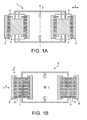
- this type of component 1 shown diagrammatically in FIG. 1A, typically comprises two coupled mobile masses 2, 2 'which vibrate at resonance (mounting in tuning fork) in the plane of the wafer 1 to which they are indirectly anchored.
- the masses 2, 2 ' are excited by means of electrostatic forces applied via structures 3, 3' in combs interlocking in the masses 2, 2 '.
- the detection can be done in the plane (X, Y) of the gyrometer 5 where vibrating moving masses 6 , again according to the principle of a capacitive detection: electrodes 7 measure the relative displacement in the Y direction of the masses 6 under the influence of an angular displacement along the Z axis and a forced vibration along X by means of combs 8.
- the invention proposes to overcome the disadvantages mentioned above.
- the invention is particularly adapted to the structures of gyrometers comparable to the state of the art, that is to say of the tuning fork type, for example micromechanical devices, with excitation of seismic masses along an axis, and generation of forces Coriolis in a direction orthogonal to this axis of vibration and the axis of rotation.
- the influence that these forces generate on another resonator associated with the moving structure is measured. Indeed, under the effect of a constraint, the natural frequency of a mechanical resonator changes: there is frequency modulation.
- the invention therefore proposes to use this effect to measure the forces resulting from the angular displacement orthogonal to a forced vibration.
- the gyroscope according to the invention comprises a first mobile resonator in a plane and comprising two masses interconnected by connecting means, means for moving the masses in a first direction of the plane, a second detection resonator connected to a first end portion at the first resonator mobile, and means for measuring the eigenmode of the detection resonator.
- the second resonator may be attached by a second end portion to a substrate which is part of the gyrometer, for example a microtechnological support for a flat monolithic gyrometer.
- the invention relates to a gyroscope provided with a device, which comprises two masses connected by a connecting frame, advantageously two parallel connecting arms connected to the masses by perpendicular bending arms, and which is movable relative to a substrate, the movement being controlled by means for moving the masses and more particularly for vibrating them, advantageously in the form of capacitive combs.
- the gyroscope further comprises at least one (second) detection resonator connected to an end portion of the mobile device, and fixed to another. Means are provided for exciting the detection resonator and measuring its resonance frequency.
- the gyro allows the detection of normal angular movements at its plane, by the generation of Coriolis forces perpendicular to the connecting arms, the masses being set in vibration, advantageously in resonance and in phase opposition , in the direction defined by the arms. Motion detection is performed in the plane of the device.
- the support is a microelectronic substrate, such as SOI monocrystalline silicon ("silicon on insulator”: silicon on insulator), and the gyrometer is micro-machined in the active part of this substrate, all the components of the gyrometer being unitary to form a monolithic gyrometer.
- SOI monocrystalline silicon silicon on insulator
- the gyrometer is micro-machined in the active part of this substrate, all the components of the gyrometer being unitary to form a monolithic gyrometer.
- the detection resonator of the gyrometer according to the invention may be in the form of a vibrating beam or a tuning fork; several resonators can be used together. Resonators can also be activated via capacitive electrodes, which can be used for both activation and detection, or decoupled for each function.
- the link arms are secured to the support by a torsion axis, advantageously in their center, in order to transform the Coriolis force into force torque on the arm, each resonator being fixed to a link arm in a manner offset from this torsion axis: the stress on the detection resonator, and thus the modification of its own mode, can thus be increased, especially since the latter is close to the torsion axis.
- the detection resonator may also be associated with other amplification means, such as rigid articulated arms.
- FIGS. 1A and 1B already described, show gyrometers according to the state of the art.
- Figure 2 shows a gyrometer according to an embodiment of the invention.
- FIG. 3 diagrammatically represents the forces in action on a resonator of a gyrometer according to the invention.
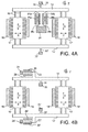
- FIGS. 4A to 4D show different configurations for the detection resonators of a gyrometer according to the invention.
- the gyrometer 10 consists of a support, not shown, and two seismic masses 12, 12 'which are movable in the plane (X, Y) of the support, and in particular which can vibrate.
- the two masses 12, 12 ' are coupled by connecting means, also movable relative to the support.
- two connecting arms 14, 14 ' here parallel, are connected to the moving masses via means 16, 16' having sufficient flexibility to allow the relative movements of the two masses 12, 12 'relative to each other. to the arms 14, 14 ', while being sufficiently rigid to transmit the mass movements 12, 12' to the arms 14, 14 ', as will be clear later.
- the link arms 14, 14 'and the flexible means, or bending arm, 16, 16' form a rectangular frame; the flexible means 16, 16 'may for example be bending springs or an attachment tongue.
- Means are provided to put the masses 12, 12 'in vibration in the plane (X, Y) of the support, for example excitation combs 18, 18' interlocking in one or both sides of each mobile mass 12 , 12 '.
- the masses 12, 12 ' are excited, preferably at resonance or in the vicinity of the resonance, by means of electrostatic forces applied via inter-digit comb structures 18, 18': 1 together the masses 12, 12 'and connecting means 14, 14', 16, 16 'thus form a first excitation resonator 20.
- the resonance operation makes it possible to obtain a high amplitude of displacement, and a large quality factor, increasing the sensitivity of the gyrometer.
- the vibration of the masses 12, 12 ' is in phase opposition, that is to say that their movements are in the opposite direction at each instant: the distance separating the two masses 12, 12' is variable, this variation being tolerated by the flexible means 16, 16 '. This allows detection by second resonators.
- This constraint moves the resonance frequency ⁇ ⁇ of the detection resonator 22.
- the rotation speed ⁇ around the Z axis is then deduced from the frequency displacement ⁇ ⁇ ⁇ measured.
- the resonator 22 is excited and preferably slaved to its resonance peak or its vicinity; a digital electronic system makes it possible to easily go back to the resonant frequency at any moment.
- the detection resonator 22 Due to its connection to the connecting arms 14, 14 ', and not to a moving mass 12, 12', the detection resonator 22 is furthermore less disturbed by the movements of the mass 12, 12 'and its sensitivity is increased .
- the resonator 22 may for example be in the form of a vibrating beam as shown schematically in Figure 2, a first end is connected to the connecting arm 14 and the other is anchored to the substrate by any means 24 known. According to a preferred embodiment, the resonator 22 is excited capacitively resonance by fixed electrodes which are also used for detection. It is also possible to have a detection electrode 26 dissociated from the excitation electrode 28. An electromagnetic excitation is can also be envisaged, just like a piezoelectric gauge detection.
- each arm 14, 14 ' is located a torsion axis 30, 30' intended to transform the Coriolis forces acting at the masses 12, 12 in a pair of forces around this torsion axis 30, 30 ', by a "lever arm” effect which makes it possible to exert the greatest possible stress on the resonator 22.
- Each of these torsion axes 30, 30 ' is thus attached at one end to the support by an anchor 32, 32', and at the other end to the link arm 14, 14 ', in their median axis.
- the anchors 32, 32 ' are advantageously arranged inside the rectangular frame 14, 14', 16, 16 'towards the center of the structure 20, to limit the temperature drifts of the gyrometer 10.
- the excitation resonator 20 is symmetrical, that is to say in particular that the two masses 12, 12 'are identical, as are the two link arms 14, 14' and the bending arms 16, 16 '. Similarly, the two masses 12, 12 'are excited in a similar manner in phase opposition.
- the resonance frequency ⁇ ⁇ of the resonator 22 detected during the angular displacement ⁇ of the gyrometer 10 makes it possible to determine this angular displacement ⁇ , without having to determine the relative displacement of the moving masses 12, 12 'due to the Coriolis F1 forces.
- the measurement of a frequency requires only a digital detection electronics, simplified compared to existing capacitive systems for displacement detection.
- this detection is performed in the plane of the device 10, which reduces the control of the spacings between the components.
- the resonator shown in FIG. 2 is only illustrative: it is possible, as shown diagrammatically in FIG. 4A, to use, for example, two detection resonators 22a, 22b on one and the same link arm 14.
- the two resonators 22a , 22b have the same proper mode ⁇ ⁇ and are mounted symmetrically with respect to the torsion axis 30: such a differential arrangement makes it possible to increase the detection sensitivity and to overcome certain non-linear effects.
- the beams 22, 22 ' are not necessarily parallel to the Y direction of the Coriolis force but may be for example parallel to the link arm 14, 14 '.
- tuning fork resonators 34 instead of beam type resonators 22, on one arm or both (FIG. 4C).
- the use of tuning fork resonators 34 makes it possible to obtain higher quality coefficients, and thus a gain in sensitivity and stability.
- the tuning fork resonators 34 may also be excited by means of fixed capacitive electrodes 36 or by electromagnetic means.
- anchor point 24 of the resonators is only schematically shown as unique for all the resonators in FIG. 4C (see for example FIG. 4B).
- the resonance frequency of the masses 12, 12 ' may be close to the resonance frequency of the mobile device 20 composed of the set of masses 12, 12', flexible means 16, 16 ' and connecting arm 14, 14 ', about its torsion axis 30, 30'.
- the eigen mode ⁇ ⁇ the detection resonator 22, 34 is substantially greater than the resonance frequency of the mobile device, or excitation resonator, 20.
- the gyrometer 10 has a high sensitivity of the sensor 22, 34, which is inherent in the frequency detection and is increased by the "lever arm” effect due to the torsion axis 30.
- the decrease in the distance d2 between the torsion axis 30 and the resonator 22, 34 also makes it possible to increase the sensitivity.
- FIG. 4D Another means of amplifying the sensitivity of the gyrometer 10 is shown in FIG. 4D: the detection system 38 is connected to an anchoring point 24 at one end 38a and at the other end 38b to the connecting arm 14.
- the two ends 38a, 38b of the resonance detection system 38 do not constitute the ends of the vibrating element 40 itself.
- the vibrating beam 40 comprises two rigid end portions 42.
- Each of the end portions 42 is connected by two rigid arms 44, 46 to the ends 38a, 38b of the detection system 38 by articulations.
- the articulated arms 44a, 44b, 46a, 46b are symmetrical and form a rhombus; they can be uniform or vary in thickness.
- the Coriolis force is perpendicular at the resonator 40: the Coriolis force causes a modification of the distance between the ends 38a, 38b of the detection system 38.
- the arms 44, 46 being rigid, the angle ⁇ between the arms 44, 46 and the resonator 40 and the The length of the vibrating beam 40 is thus modified, which causes a displacement of the resonance frequency of the beam 40, which is excited by fixed electrodes 48 for example.
- the angle ⁇ makes it possible to play directly on the amplification coefficient. It is clear that other configurations for the arms 44, 46 are possible for the same result.
- the gyroscope 10 has a low sensitivity to transverse accelerations, and therefore a better determination of the angular displacement ⁇ . There are also no coupling phenomena between the excitation resonance frequency and the natural frequency. ⁇ ⁇ detection resonator 22, 34, 40 in contrast to possible interference during a capacitive detection.
- the gyro according to the invention is thus very sensitive, stable and simplified compared to gyrometers of the same type existing thanks to direct digital electronic processing in particular. It is clear that the various embodiments shown in the figures can easily be combined.
- the gyro 10 according to the invention can be manufactured according to all the techniques known in micro technology, and more particularly in microelectronics.
- the substrate is made of silicon, in particular monocrystalline, of the SOI type, which increases the quality factor.
- the thickness of the initial silicon wafer is a few hundred micrometers, for example 525 ⁇ m, on which there is a thin layer, for example of 0.4 ⁇ m, of SiO 2 , itself covered with a layer more thick monocrystalline silicon which will determine the thickness of the elements of the gyrometer 10, for example of the order of 60 microns.
- the machining of the gyrometer 10 consists in etching in the upper layer of silicon (for example by lithography) as far as the oxide layer the desired surface patterns, namely the shape of the elements of the first resonator 20 and the detection resonator 22. 34, 40 of the gyrometer 10. Then, the underlying oxide layer is removed, for example by selective etching, except for the anchoring points 24, 32. A suspension structure is thus obtained on the substrate, maintained at a distance of the order of the thickness of the initial oxide layer by the anchoring points, and free to be set in motion, and in particular in vibration.
Landscapes
- Physics & Mathematics (AREA)
- Engineering & Computer Science (AREA)
- General Physics & Mathematics (AREA)
- Radar, Positioning & Navigation (AREA)
- Remote Sensing (AREA)
- Gyroscopes (AREA)
- Pressure Sensors (AREA)
Applications Claiming Priority (1)
| Application Number | Priority Date | Filing Date | Title |
|---|---|---|---|
| FR0451849A FR2874257B1 (fr) | 2004-08-13 | 2004-08-13 | Micro gyrometre a detection frenquentielle |
Publications (2)
| Publication Number | Publication Date |
|---|---|
| EP1626282A1 true EP1626282A1 (de) | 2006-02-15 |
| EP1626282B1 EP1626282B1 (de) | 2010-03-10 |
Family
ID=34947826
Family Applications (1)
| Application Number | Title | Priority Date | Filing Date |
|---|---|---|---|
| EP05107425A Active EP1626282B1 (de) | 2004-08-13 | 2005-08-12 | Mikrokreisel mit Frequenzdetektion |
Country Status (5)
| Country | Link |
|---|---|
| US (1) | US7389690B2 (de) |
| EP (1) | EP1626282B1 (de) |
| JP (1) | JP2006053152A (de) |
| DE (1) | DE602005019817D1 (de) |
| FR (1) | FR2874257B1 (de) |
Cited By (5)
| Publication number | Priority date | Publication date | Assignee | Title |
|---|---|---|---|---|
| FR2917731A1 (fr) * | 2007-06-25 | 2008-12-26 | Commissariat Energie Atomique | Dispositif resonant a detection piezoresistive realise en technologies de surface |
| EP2211143A1 (de) | 2009-01-23 | 2010-07-28 | Commissariat à l'Énergie Atomique et aux Énergies Alternatives | Planarer mikromechanischer Kreisel mit Messung ausserhalb der Ebene mittels Dehnungsmesser |
| CN102874736A (zh) * | 2011-07-14 | 2013-01-16 | 中国科学院微电子研究所 | 横向梳齿型微机械震动能量收集器 |
| US8371166B2 (en) | 2009-01-23 | 2013-02-12 | Commissariat A L'energie Atomique | Inertial or resonating sensor in surface technology, with out of plane detection by strain gauge |
| CN110595509A (zh) * | 2019-09-30 | 2019-12-20 | 中国船舶重工集团公司第七0七研究所 | 一种用于低阻尼谐振子参数测试的敲击装置 |
Families Citing this family (26)
| Publication number | Priority date | Publication date | Assignee | Title |
|---|---|---|---|---|
| FR2898884B1 (fr) * | 2006-03-27 | 2008-05-02 | Commissariat Energie Atomique | Micro-capteur inertiel resonant a epaisseur variable realise en technologies de surface |
| US7639104B1 (en) * | 2007-03-09 | 2009-12-29 | Silicon Clocks, Inc. | Method for temperature compensation in MEMS resonators with isolated regions of distinct material |
| US7956517B1 (en) * | 2007-05-10 | 2011-06-07 | Silicon Laboratories | MEMS structure having a stress inverter temperature-compensated resonator member |
| US8061201B2 (en) * | 2007-07-13 | 2011-11-22 | Georgia Tech Research Corporation | Readout method and electronic bandwidth control for a silicon in-plane tuning fork gyroscope |
| FR2924422B1 (fr) * | 2007-11-30 | 2009-12-25 | Commissariat Energie Atomique | Dispositif a detection par jauge de contrainte piezoresistive suspendue comportant une cellule d'amplification de contrainte. |
| JP4561820B2 (ja) * | 2007-12-21 | 2010-10-13 | 株式会社豊田中央研究所 | 角速度センサ |
| KR101458837B1 (ko) | 2008-06-12 | 2014-11-07 | 세종대학교산학협력단 | 듀얼매스 자이로스코프의 진동 제어방법 |
| US7944124B1 (en) * | 2008-08-29 | 2011-05-17 | Silicon Laboratories Inc. | MEMS structure having a stress-inducer temperature-compensated resonator member |
| US8584524B2 (en) * | 2008-10-21 | 2013-11-19 | ISC8 Inc. | Nano-resonator inertial sensor assembly |
| US8443665B2 (en) * | 2008-10-21 | 2013-05-21 | Ying W. Hsu | Frequency modulated micro gyro |
| JP2010117293A (ja) * | 2008-11-14 | 2010-05-27 | Alps Electric Co Ltd | 角速度センサ |
| FI20095201A0 (fi) * | 2009-03-02 | 2009-03-02 | Vti Technologies Oy | Värähtelevä mikromekaaninen kulmanopeusanturi |
| DE102009048139A1 (de) * | 2009-10-02 | 2011-04-07 | Siemens Aktiengesellschaft | Mikromechanischer Sensor |
| DE102010029630A1 (de) * | 2010-06-02 | 2011-12-08 | Robert Bosch Gmbh | Drehratensensor |
| TWI453371B (zh) * | 2011-12-30 | 2014-09-21 | Ind Tech Res Inst | 一種具振盪模組的微機電系統裝置 |
| WO2017105594A2 (en) | 2015-10-06 | 2017-06-22 | The Charles Stark Draper Laboratory, Inc. | Magnetic field detector system |
| US10564200B2 (en) | 2015-10-06 | 2020-02-18 | The Charles Stark Draper Laboratory, Inc. | Electric field detector system |
| US10018686B1 (en) | 2015-10-21 | 2018-07-10 | The Charles Stark Draper Laboratory, Inc. | Ultra-low noise sensor for magnetic fields |
| US10531805B2 (en) | 2016-09-30 | 2020-01-14 | The Charles Stark Draper Laboratory, Inc. | Biophysical sensing systems and methods using non-contact electric field detectors |
| US10859620B2 (en) | 2017-04-04 | 2020-12-08 | The Charles Stark Draper Laboratory, Inc. | Miniature electric field detector |
| DE102017213644A1 (de) * | 2017-08-07 | 2019-02-07 | Robert Bosch Gmbh | Drehratensensor, Verfahren zur Herstellung eines Drehratensensors |
| US11525870B2 (en) | 2017-10-05 | 2022-12-13 | The Charles Stark Draper Laboratory, Inc. | Electromagnetic gradiometers |
| DE102017217975A1 (de) * | 2017-10-10 | 2019-04-11 | Robert Bosch Gmbh | Mikromechanische Federstruktur |
| US12089941B2 (en) | 2019-03-15 | 2024-09-17 | The Charles Stark Draper Laboratory, Inc. | Miniature electric field detector |
| TWI716239B (zh) | 2019-12-26 | 2021-01-11 | 財團法人工業技術研究院 | 一種可感測低頻力與高頻力的力感測裝置 |
| EP4180764A1 (de) * | 2021-11-10 | 2023-05-17 | Murata Manufacturing Co., Ltd. | Doppelhebelkupplung |
Citations (3)
| Publication number | Priority date | Publication date | Assignee | Title |
|---|---|---|---|---|
| EP0507338A1 (de) * | 1991-04-05 | 1992-10-07 | Japan Aviation Electronics Industry, Limited | Trägerstruktur für einen Beschleunigungsmesser vom Oszillatortyp |
| US6032531A (en) * | 1997-08-04 | 2000-03-07 | Kearfott Guidance & Navigation Corporation | Micromachined acceleration and coriolis sensor |
| US20040154400A1 (en) * | 2003-02-07 | 2004-08-12 | Johnson Burgess R. | Methods and systems for simultaneously fabricating multi-frequency MEMS devices |
Family Cites Families (7)
| Publication number | Priority date | Publication date | Assignee | Title |
|---|---|---|---|---|
| DE4414237A1 (de) * | 1994-04-23 | 1995-10-26 | Bosch Gmbh Robert | Mikromechanischer Schwinger eines Schwingungsgyrometers |
| US6250156B1 (en) | 1996-05-31 | 2001-06-26 | The Regents Of The University Of California | Dual-mass micromachined vibratory rate gyroscope |
| JPH10170275A (ja) * | 1996-12-13 | 1998-06-26 | Toyota Central Res & Dev Lab Inc | 振動型角速度センサ |
| JP2003042768A (ja) * | 2001-07-26 | 2003-02-13 | Microstone Corp | 運動センサ |
| US6487864B1 (en) | 2002-04-23 | 2002-12-03 | Honeywell International Inc. | Cyrogenic inertial micro-electro-mechanical system (MEMS) device |
| US6843127B1 (en) * | 2003-07-30 | 2005-01-18 | Motorola, Inc. | Flexible vibratory micro-electromechanical device |
| US7043985B2 (en) * | 2004-01-13 | 2006-05-16 | Georgia Tech Research Corporation | High-resolution in-plane tuning fork gyroscope and methods of fabrication |
-
2004
- 2004-08-13 FR FR0451849A patent/FR2874257B1/fr not_active Expired - Lifetime
-
2005
- 2005-08-12 EP EP05107425A patent/EP1626282B1/de active Active
- 2005-08-12 US US11/202,148 patent/US7389690B2/en active Active
- 2005-08-12 DE DE602005019817T patent/DE602005019817D1/de active Active
- 2005-08-12 JP JP2005234782A patent/JP2006053152A/ja active Pending
Patent Citations (3)
| Publication number | Priority date | Publication date | Assignee | Title |
|---|---|---|---|---|
| EP0507338A1 (de) * | 1991-04-05 | 1992-10-07 | Japan Aviation Electronics Industry, Limited | Trägerstruktur für einen Beschleunigungsmesser vom Oszillatortyp |
| US6032531A (en) * | 1997-08-04 | 2000-03-07 | Kearfott Guidance & Navigation Corporation | Micromachined acceleration and coriolis sensor |
| US20040154400A1 (en) * | 2003-02-07 | 2004-08-12 | Johnson Burgess R. | Methods and systems for simultaneously fabricating multi-frequency MEMS devices |
Cited By (8)
| Publication number | Priority date | Publication date | Assignee | Title |
|---|---|---|---|---|
| FR2917731A1 (fr) * | 2007-06-25 | 2008-12-26 | Commissariat Energie Atomique | Dispositif resonant a detection piezoresistive realise en technologies de surface |
| US8156807B2 (en) | 2007-06-25 | 2012-04-17 | Commissariat A L'energie Atomique | Piezo-resistive detection resonant device made using surface technologies |
| EP2008965A3 (de) * | 2007-06-25 | 2013-10-23 | Commissariat à l'Énergie Atomique et aux Énergies Alternatives | Resonanzvorrichtung mit piezoelektrischer Erfassung für den Einsatz in Oberflächentechnologien |
| EP2211143A1 (de) | 2009-01-23 | 2010-07-28 | Commissariat à l'Énergie Atomique et aux Énergies Alternatives | Planarer mikromechanischer Kreisel mit Messung ausserhalb der Ebene mittels Dehnungsmesser |
| US8371166B2 (en) | 2009-01-23 | 2013-02-12 | Commissariat A L'energie Atomique | Inertial or resonating sensor in surface technology, with out of plane detection by strain gauge |
| US8375788B2 (en) | 2009-01-23 | 2013-02-19 | Commissariat A L'energie Atomique | Gyrometer in surface technology, with out-of-plane detection by strain gauge |
| CN102874736A (zh) * | 2011-07-14 | 2013-01-16 | 中国科学院微电子研究所 | 横向梳齿型微机械震动能量收集器 |
| CN110595509A (zh) * | 2019-09-30 | 2019-12-20 | 中国船舶重工集团公司第七0七研究所 | 一种用于低阻尼谐振子参数测试的敲击装置 |
Also Published As
| Publication number | Publication date |
|---|---|
| FR2874257B1 (fr) | 2006-10-13 |
| FR2874257A1 (fr) | 2006-02-17 |
| JP2006053152A (ja) | 2006-02-23 |
| US20060032306A1 (en) | 2006-02-16 |
| US7389690B2 (en) | 2008-06-24 |
| EP1626282B1 (de) | 2010-03-10 |
| DE602005019817D1 (de) | 2010-04-22 |
Similar Documents
| Publication | Publication Date | Title |
|---|---|---|
| EP1626282B1 (de) | Mikrokreisel mit Frequenzdetektion | |
| EP2367015B1 (de) | Rauscharmer kraftsensor | |
| EP2008965B1 (de) | Resonanzvorrichtung mit piezoelektrischer Erfassung für den Einsatz in Oberflächentechnologien | |
| EP2520940B1 (de) | Trägheitseinheit mit mehreren Erkennungsachsen | |
| EP2430397B1 (de) | Koppelstruktur für einen resonanzkreisel | |
| EP2656006B1 (de) | Planare struktur für ein dreiachsiges gyrometer | |
| EP2065713B1 (de) | Erfassungsvorrichtung mittels aufgehängtem Dehnungsmesser mit piezoelektrischem Widerstand, der eine Dehnungsverstärkungszelle umfasst | |
| EP2617130B1 (de) | Resonanter piezoresistiver detektor mit einem an das trägerelement des detektors elastisch angeschlossenen resonator und verfahren zur herstellung dieses detektors | |
| EP2449344B1 (de) | Mikromechanischer kreisel mit erkennung auf der ebene der bearbeiteten platte | |
| EP1153267B1 (de) | Stimmgabelumdrehungsmesser | |
| EP0915323A1 (de) | Mikromechanischer Schwingkreisel | |
| EP1912075A1 (de) | Beschleunigungssensor mit Ausgleichsmassen ausgestattetem Stimmgabelschwinger | |
| EP1570275B1 (de) | Beschleunigungssensor mit vibrierenden schwingbalken | |
| EP3394564B1 (de) | System zur aufhängung einer beweglichen masse mit vorrichtung zur verbindung der beweglichen masse mit optimierter linearität | |
| WO2004042324A1 (fr) | Capteur gyrometrique micro-usine, a detection dans le plan de la plaque usinee | |
| EP1235074B1 (de) | Miniaturisierter Beschleunigungsmesser mit zwei Masse-Zellen | |
| EP3971523A2 (de) | Kupplungsvorrichtung zum verbinden von zwei elementen in bewegung | |
| FR2860865A1 (fr) | Gyrometre micromecanique infertiel a diapason | |
| EP2102665B1 (de) | Führungsklinge für eine prüfmasse und eine solche klinge verwendendes mikrobearbeitetes elektromechanisches system | |
| FR3140621A1 (fr) | Dispositif micro-électromécanique |
Legal Events
| Date | Code | Title | Description |
|---|---|---|---|
| PUAI | Public reference made under article 153(3) epc to a published international application that has entered the european phase |
Free format text: ORIGINAL CODE: 0009012 |
|
| AK | Designated contracting states |
Kind code of ref document: A1 Designated state(s): AT BE BG CH CY CZ DE DK EE ES FI FR GB GR HU IE IS IT LI LT LU LV MC NL PL PT RO SE SI SK TR |
|
| AX | Request for extension of the european patent |
Extension state: AL BA HR MK YU |
|
| 17P | Request for examination filed |
Effective date: 20060725 |
|
| 17Q | First examination report despatched |
Effective date: 20060829 |
|
| AKX | Designation fees paid |
Designated state(s): DE GB IT |
|
| RAP1 | Party data changed (applicant data changed or rights of an application transferred) |
Owner name: COMMISSARIAT A L'ENERGIE ATOMIQUE |
|
| GRAP | Despatch of communication of intention to grant a patent |
Free format text: ORIGINAL CODE: EPIDOSNIGR1 |
|
| GRAS | Grant fee paid |
Free format text: ORIGINAL CODE: EPIDOSNIGR3 |
|
| GRAA | (expected) grant |
Free format text: ORIGINAL CODE: 0009210 |
|
| AK | Designated contracting states |
Kind code of ref document: B1 Designated state(s): DE GB IT |
|
| REG | Reference to a national code |
Ref country code: GB Ref legal event code: FG4D Free format text: NOT ENGLISH |
|
| REF | Corresponds to: |
Ref document number: 602005019817 Country of ref document: DE Date of ref document: 20100422 Kind code of ref document: P |
|
| PLBE | No opposition filed within time limit |
Free format text: ORIGINAL CODE: 0009261 |
|
| STAA | Information on the status of an ep patent application or granted ep patent |
Free format text: STATUS: NO OPPOSITION FILED WITHIN TIME LIMIT |
|
| 26N | No opposition filed |
Effective date: 20101213 |
|
| PGFP | Annual fee paid to national office [announced via postgrant information from national office to epo] |
Ref country code: IT Payment date: 20110822 Year of fee payment: 7 |
|
| PG25 | Lapsed in a contracting state [announced via postgrant information from national office to epo] |
Ref country code: IT Free format text: LAPSE BECAUSE OF NON-PAYMENT OF DUE FEES Effective date: 20120812 |
|
| GBPC | Gb: european patent ceased through non-payment of renewal fee |
Effective date: 20180812 |
|
| PG25 | Lapsed in a contracting state [announced via postgrant information from national office to epo] |
Ref country code: GB Free format text: LAPSE BECAUSE OF NON-PAYMENT OF DUE FEES Effective date: 20180812 |
|
| PGFP | Annual fee paid to national office [announced via postgrant information from national office to epo] |
Ref country code: DE Payment date: 20230822 Year of fee payment: 19 |