EP1624236A1 - Fluid control device with heater - Google Patents
Fluid control device with heater Download PDFInfo
- Publication number
- EP1624236A1 EP1624236A1 EP04728249A EP04728249A EP1624236A1 EP 1624236 A1 EP1624236 A1 EP 1624236A1 EP 04728249 A EP04728249 A EP 04728249A EP 04728249 A EP04728249 A EP 04728249A EP 1624236 A1 EP1624236 A1 EP 1624236A1
- Authority
- EP
- European Patent Office
- Prior art keywords
- fluid control
- heat insulating
- heating apparatus
- control apparatus
- insulating board
- Prior art date
- Legal status (The legal status is an assumption and is not a legal conclusion. Google has not performed a legal analysis and makes no representation as to the accuracy of the status listed.)
- Withdrawn
Links
Images

Classifications
-
- F—MECHANICAL ENGINEERING; LIGHTING; HEATING; WEAPONS; BLASTING
- F16—ENGINEERING ELEMENTS AND UNITS; GENERAL MEASURES FOR PRODUCING AND MAINTAINING EFFECTIVE FUNCTIONING OF MACHINES OR INSTALLATIONS; THERMAL INSULATION IN GENERAL
- F16K—VALVES; TAPS; COCKS; ACTUATING-FLOATS; DEVICES FOR VENTING OR AERATING
- F16K51/00—Other details not peculiar to particular types of valves or cut-off apparatus
- F16K51/02—Other details not peculiar to particular types of valves or cut-off apparatus specially adapted for high-vacuum installations
-
- F—MECHANICAL ENGINEERING; LIGHTING; HEATING; WEAPONS; BLASTING
- F16—ENGINEERING ELEMENTS AND UNITS; GENERAL MEASURES FOR PRODUCING AND MAINTAINING EFFECTIVE FUNCTIONING OF MACHINES OR INSTALLATIONS; THERMAL INSULATION IN GENERAL
- F16K—VALVES; TAPS; COCKS; ACTUATING-FLOATS; DEVICES FOR VENTING OR AERATING
- F16K49/00—Means in or on valves for heating or cooling
-
- F—MECHANICAL ENGINEERING; LIGHTING; HEATING; WEAPONS; BLASTING
- F16—ENGINEERING ELEMENTS AND UNITS; GENERAL MEASURES FOR PRODUCING AND MAINTAINING EFFECTIVE FUNCTIONING OF MACHINES OR INSTALLATIONS; THERMAL INSULATION IN GENERAL
- F16K—VALVES; TAPS; COCKS; ACTUATING-FLOATS; DEVICES FOR VENTING OR AERATING
- F16K27/00—Construction of housing; Use of materials therefor
- F16K27/003—Housing formed from a plurality of the same valve elements
-
- Y—GENERAL TAGGING OF NEW TECHNOLOGICAL DEVELOPMENTS; GENERAL TAGGING OF CROSS-SECTIONAL TECHNOLOGIES SPANNING OVER SEVERAL SECTIONS OF THE IPC; TECHNICAL SUBJECTS COVERED BY FORMER USPC CROSS-REFERENCE ART COLLECTIONS [XRACs] AND DIGESTS
- Y10—TECHNICAL SUBJECTS COVERED BY FORMER USPC
- Y10T—TECHNICAL SUBJECTS COVERED BY FORMER US CLASSIFICATION
- Y10T137/00—Fluid handling
- Y10T137/6416—With heating or cooling of the system
- Y10T137/6606—With electric heating element
-
- Y—GENERAL TAGGING OF NEW TECHNOLOGICAL DEVELOPMENTS; GENERAL TAGGING OF CROSS-SECTIONAL TECHNOLOGIES SPANNING OVER SEVERAL SECTIONS OF THE IPC; TECHNICAL SUBJECTS COVERED BY FORMER USPC CROSS-REFERENCE ART COLLECTIONS [XRACs] AND DIGESTS
- Y10—TECHNICAL SUBJECTS COVERED BY FORMER USPC
- Y10T—TECHNICAL SUBJECTS COVERED BY FORMER US CLASSIFICATION
- Y10T137/00—Fluid handling
- Y10T137/8593—Systems
- Y10T137/877—With flow control means for branched passages
- Y10T137/87885—Sectional block structure
Definitions
- the present invention relates to a fluid control apparatus used in a semiconductor manufacturing apparatus or the like, and more particularly to a fluid control apparatus with a heating apparatus.
- a fluid control apparatus used in a semiconductor manufacturing apparatus is structured such that various fluid control devices are arranged in plural lines, and flow paths of the fluid control devices in adjacent lines are connected at a predetermined position by a device connecting means.
- this kind of fluid control apparatus has been made progressively integrated by connecting a mass flow controller, an opening and closing valve and the like without any tube.
- a heating apparatus is required for the purpose of such as condensation prevention and reliquefaction prevention at a time of gasifying a fluid, which is a liquid at room temperature, so as to flow.
- a structure in which right and left tape heaters are arranged as the fluid control apparatus with the heating apparatus mentioned above in both sides of at least one line, and the right and left tape heaters are held to corresponding joint members by a plurality of metal clips has been disclosed (Japanese Unexamined Patent Publication No. 2002-267100).
- An object of the present invention is to provide a fluid control apparatus with a heating apparatus which improves a heating capacity as well as inhibiting an increase of an installation area due to an addition of a heating apparatus.
- a fluid control apparatus with a heating apparatus in accordance with the invention is such that a fluid control apparatus with a heating apparatus in which the heating apparatus is provided in the fluid control apparatus structured such that lines formed by a plurality of fluid control devices arranged in an upper stage and a plurality of block-like joint members arranged in a lower stage are arranged in parallel in a base member, characterized in that sheet heaters are arranged in both sides of at least one line, heat insulating boards are respectively brought into contact with outer sides of the sheet heaters, and the heat insulating boards are coupled to each other by at least one thread member, whereby the sheet heater is prevented from dropping out.
- a material of the heat insulating board preferably employs a material which is excellent in a heat resisting property and a heat insulating property, and is made, for example, of an engineering plastic.
- a coefficient of thermal conductivity of the heat insulating board is preferably equal to or less than 1.0 (W/m ⁇ K), and more preferably equal to or less than 0.30 (W/m ⁇ K).
- the heat insulating boards are respectively brought into contact with the outer sides of the sheet heaters, and the heat insulating boards are coupled to each other by the thread member, it is possible to inhibit an increase of an installation area due to the addition of the heating apparatus, and it is possible to heat a desired line by a little labor hour.
- a coefficient of thermal conductivity of the heat insulating board made of the engineering plastic is smaller in comparison with the metal clip (a coefficient of thermal conductivity of a stainless steel is 16.3 W/m ⁇ K), it is possible to heat the line to a higher temperature on the basis of a heat insulating effect even in the case that the same heater is used.
- each of the heat insulating boards is provided with at least one protruding portion extending in a direction of the other heat insulating board, and leading ends of the protruding portions are confronted with each other, and it is more preferable that a bolt insertion hole inserting and passing a coupling bolt is provided in the protruding portion of one heat insulating board, and a female thread portion with which the coupling bolt is screwed is provided in the protruding portion of the other heat insulating board, respectively.
- an interval between the heat insulating boards is kept constant, and it is possible to easily execute a screw coupling work.
- FIGs. 1 and 2 show a part of a fluid control apparatus with a heating apparatus in accordance with the invention.
- a fluid control apparatus 1 is formed such that lines formed by a plurality of fluid control devices 2, 3 and 4 arranged in an upper stage and a plurality of block-like joint members 5 arranged in a lower stage are arranged in parallel in a base member (not shown).
- a heating apparatus 11 has sheet heaters 12 arranged in both right and left sides of at least one line and heating the fluid control devices 2, 3 and 4 and the joint members 5, left and right heat insulating boards 13 and 14 made of an engineering plastic are brought into contact with left and right outer sides of the sheet heaters 12, and the left and right heat insulating boards 13 and 14 facing to each other are coupled by two bolts (at least one thread member) 15 with a hexagonal hole, whereby the sheet heater 12 is prevented from dropping out from the fluid control devices 2, 3 and 4 and the joint members 5.
- a height of a center portion is set to a height which can cover main bodies of the fluid control devices 2, 3 and 4 and an entire of the joint members 5, both end portion thereof is made higher than the center portion, and an entire is formed in an approximately-U shape.
- a shape of the sheet heater is not limited to the approximately-U shape, but may be of course in a band shape in which a height is fixed.
- the left and right heat insulating boards 13 and 14 are set to approximately the same height as the height of the center portion of the sheet heater 12, and a portion near both end portions is protruded to an upper side. Upper protruding portions thereof are respectively provided with protruding portions 13a, 13b, 14a and 14b extending in a direction of the other heat insulating boards 13 and 14, and leadings ends of the protruding portions 13a, 13b, 14a and 14b are confronted with each other.
- the protruding portions 13a and 13b of the left heat insulating board 13 have a larger protruding amount than that of the protruding portions 14a and 14b of the right heat insulating board 13.
- Each of the protruding portions 13a, 13b, 14a and 14b is received by upper surfaces of the main bodies of the fluid control devices 2, 3 and 4.
- One protruding portions 13a and 14a of the protruding portions 13a, 13b, 14a and 14b are arranged between the higher fluid control devices 3, and the other protruding portions 13b and 14b are arranged between the lower fluid control devices 4.
- the protruding portion 13a of the left heat insulating board 13 arranged between the higher fluid control devices 3 is formed in a shape obtained by partly notching the other protruding portion 13b of the left heat insulating board 13 in order to avoid an interference with the fluid control device 3.
- the protruding portions 14a and 14b of the right heat insulating boards 14 are provided with a bolt insertion hole 16 for inserting a coupling bolt 15, and the protruding portions 13a and 13b of the left heat insulating board 13 are provided with a female thread portion 17 with which the coupling bolt 15 is screwed, respectively.
- a kind of the engineering plastic forming the heat insulating boards 13 and 14 is not particularly limited, however, it is preferable that a coefficient of thermal conductivity thereof is equal to or less than 0.30 (W/m ⁇ K), and there can be exemplified a PEEK in which a coefficient of thermal conductivity is 0.25 (W/m ⁇ K), a ULTEM in which a coefficient of thermal conductivity is 0.22 (W/m ⁇ K), an MC nylon in which a coefficient of thermal conductivity is 0.18 (W/m ⁇ K) and the like.
- a material forming the heat insulating boards 13 and 14 may be of course constituted by the other material than the engineering plastic, however, a coefficient of thermal conductivity in this case is set to be equal to or less than 1.0 (W/m ⁇ K), is more preferably set to be equal to or less than 0.30 (W/m ⁇ K).
- a fluid control apparatus used in such as a semiconductor manufacturing apparatus, capable of preventing the condensation and the reliquefaction at a time of gasifying the fluid corresponding to the liquid at the room temperature so as to flow, or the like, and having a high performance and a high general-purpose property.
Landscapes
- Engineering & Computer Science (AREA)
- General Engineering & Computer Science (AREA)
- Mechanical Engineering (AREA)
- Resistance Heating (AREA)
- Details Of Valves (AREA)
- Instantaneous Water Boilers, Portable Hot-Water Supply Apparatuses, And Control Of Portable Hot-Water Supply Apparatuses (AREA)
- Valve Housings (AREA)
Abstract
Description
- The present invention relates to a fluid control apparatus used in a semiconductor manufacturing apparatus or the like, and more particularly to a fluid control apparatus with a heating apparatus.
- A fluid control apparatus used in a semiconductor manufacturing apparatus is structured such that various fluid control devices are arranged in plural lines, and flow paths of the fluid control devices in adjacent lines are connected at a predetermined position by a device connecting means. In recent years, however, this kind of fluid control apparatus has been made progressively integrated by connecting a mass flow controller, an opening and closing valve and the like without any tube.
- In this kind of fluid control apparatus, there is a case that a heating apparatus is required for the purpose of such as condensation prevention and reliquefaction prevention at a time of gasifying a fluid, which is a liquid at room temperature, so as to flow. As this type of fluid control apparatus with a heating apparatus, a structure in which right and left tape heaters are arranged as the fluid control apparatus with the heating apparatus mentioned above in both sides of at least one line, and the right and left tape heaters are held to corresponding joint members by a plurality of metal clips has been disclosed (Japanese Unexamined Patent Publication No. 2002-267100).
- In accordance with the conventional fluid control apparatus with the heating apparatus mentioned above, there is an advantage that an increase of an installation area due to an addition of the heating apparatus may be inhibited. However, it is not possible to sufficiently bring the heater into close contact with a fluid control device main body or the like, only with an elastic force by the clips. Accordingly, there is a case that a heating capacity comes short with respect to a required temperature, for example, a case that it is possible to heat to about 50 °C but it is not possible to heat to 80 °C or more. Although a structure in which a silicone sponge is adhered as a heat insulating material to the heater and the heater is pinched on the silicone sponge by the clips may also be conceived, there is a problem in this case that an increase in the thickness of the heater including the silicone sponge makes the heater not suitable to be used in the fluid control apparatus in which the integration mentioned above is required. It is of course possible to increase a power of the heater so as to increase a heating capacity. However, in this case, there is a problem that an electric power consumption increases, and economical and energy losses are caused.
- An object of the present invention is to provide a fluid control apparatus with a heating apparatus which improves a heating capacity as well as inhibiting an increase of an installation area due to an addition of a heating apparatus.
- A fluid control apparatus with a heating apparatus in accordance with the invention is such that a fluid control apparatus with a heating apparatus in which the heating apparatus is provided in the fluid control apparatus structured such that lines formed by a plurality of fluid control devices arranged in an upper stage and a plurality of block-like joint members arranged in a lower stage are arranged in parallel in a base member, characterized in that sheet heaters are arranged in both sides of at least one line, heat insulating boards are respectively brought into contact with outer sides of the sheet heaters, and the heat insulating boards are coupled to each other by at least one thread member, whereby the sheet heater is prevented from dropping out.
- A material of the heat insulating board preferably employs a material which is excellent in a heat resisting property and a heat insulating property, and is made, for example, of an engineering plastic. A coefficient of thermal conductivity of the heat insulating board is preferably equal to or less than 1.0 (W/m·K), and more preferably equal to or less than 0.30 (W/m·K).
- In accordance with the fluid control apparatus of the invention, since the sheet heaters are arranged in both sides of the line requiring a heat application, the heat insulating boards are respectively brought into contact with the outer sides of the sheet heaters, and the heat insulating boards are coupled to each other by the thread member, it is possible to inhibit an increase of an installation area due to the addition of the heating apparatus, and it is possible to heat a desired line by a little labor hour. Further, since a coefficient of thermal conductivity of the heat insulating board made of the engineering plastic is smaller in comparison with the metal clip (a coefficient of thermal conductivity of a stainless steel is 16.3 W/m·K), it is possible to heat the line to a higher temperature on the basis of a heat insulating effect even in the case that the same heater is used.
- It is preferable that an upper portion of each of the heat insulating boards is provided with at least one protruding portion extending in a direction of the other heat insulating board, and leading ends of the protruding portions are confronted with each other, and it is more preferable that a bolt insertion hole inserting and passing a coupling bolt is provided in the protruding portion of one heat insulating board, and a female thread portion with which the coupling bolt is screwed is provided in the protruding portion of the other heat insulating board, respectively.
- In accordance with the structure mentioned above, an interval between the heat insulating boards is kept constant, and it is possible to easily execute a screw coupling work.
-
- Fig. 1 is an exploded perspective view showing a fluid control apparatus with a heating apparatus in accordance with the invention.
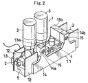
- Fig. 2 is a perspective view of the fluid control apparatus with the heating apparatus in accordance with the invention.
- A description will be given below of an embodiment in accordance with the invention with reference to the accompanying drawings.
- Figs. 1 and 2 show a part of a fluid control apparatus with a heating apparatus in accordance with the invention. A fluid control apparatus 1 is formed such that lines formed by a plurality of
fluid control devices joint members 5 arranged in a lower stage are arranged in parallel in a base member (not shown). - A heating apparatus 11, has
sheet heaters 12 arranged in both right and left sides of at least one line and heating thefluid control devices joint members 5, left and rightheat insulating boards sheet heaters 12, and the left and rightheat insulating boards sheet heater 12 is prevented from dropping out from thefluid control devices joint members 5. - In the
sheet heater 12, a height of a center portion is set to a height which can cover main bodies of thefluid control devices joint members 5, both end portion thereof is made higher than the center portion, and an entire is formed in an approximately-U shape. A shape of the sheet heater is not limited to the approximately-U shape, but may be of course in a band shape in which a height is fixed. - The left and right
heat insulating boards sheet heater 12, and a portion near both end portions is protruded to an upper side. Upper protruding portions thereof are respectively provided with protrudingportions heat insulating boards protruding portions portions heat insulating board 13 have a larger protruding amount than that of the protrudingportions 14a and 14b of the rightheat insulating board 13. - Each of the
protruding portions fluid control devices portions protruding portions fluid control devices 3, and the other protrudingportions 13b and 14b are arranged between the lower fluid control devices 4. The protrudingportion 13a of the leftheat insulating board 13 arranged between the higherfluid control devices 3 is formed in a shape obtained by partly notching the other protrudingportion 13b of the leftheat insulating board 13 in order to avoid an interference with thefluid control device 3. - As shown in Fig. 1, the protruding
portions 14a and 14b of the rightheat insulating boards 14 are provided with abolt insertion hole 16 for inserting acoupling bolt 15, and the protrudingportions heat insulating board 13 are provided with afemale thread portion 17 with which thecoupling bolt 15 is screwed, respectively. - In accordance with the structure mentioned above, a kind of the engineering plastic forming the
heat insulating boards heat insulating boards - Because the increase of the installation area due to the addition of the heating apparatus may be inhibited and the heating capacity may be improved, it is possible to provide a fluid control apparatus, used in such as a semiconductor manufacturing apparatus, capable of preventing the condensation and the reliquefaction at a time of gasifying the fluid corresponding to the liquid at the room temperature so as to flow, or the like, and having a high performance and a high general-purpose property.
Claims (5)
- A fluid control apparatus with a heating apparatus in which the heating apparatus is provided in the fluid control apparatus structured such that lines formed by a plurality of fluid control devices arranged in an upper stage and a plurality of block-like joint members arranged in a lower stage are arranged in parallel in a base member, characterized in that
the heating apparatus has sheet heaters arranged in both sides of at least one line and heating the fluid control devices and the joint members, heat insulating boards are respectively brought into contact with outer sides of the sheet heaters, and the heat insulating boards are coupled to each other by at least one thread member, whereby the sheet heater is prevented from dropping out. - A fluid control apparatus with a heating apparatus according to claim 1, wherein
an upper portion of each of the heat insulating boards is provided with at least one protruding portion extending in a direction of the other heat insulating board, and leading ends of the at least one protruding portion are confronted with each other. - A fluid control apparatus with a heating apparatus according to claim 2, wherein
a bolt insertion hole inserting and passing a coupling bolt is provided in the protruding portion of one heat insulating board, and a female thread portion with which the coupling bolt is screwed is provided in the protruding portion of the other heat insulating board, respectively. - A fluid control apparatus with a heating apparatus according to one of claims 1 to 3, wherein
the heat insulating board is made of an engineering plastic. - A fluid control apparatus with a heating apparatus according to one of claims 1 to 3, wherein
a coefficient of thermal conductivity of the heat insulating board is equal to or less than 0.30 (W/m·K).
Applications Claiming Priority (2)
| Application Number | Priority Date | Filing Date | Title |
|---|---|---|---|
| JP2003135541A JP2004340199A (en) | 2003-05-14 | 2003-05-14 | Fluid control device with heater |
| PCT/JP2004/005549 WO2004102054A1 (en) | 2003-05-14 | 2004-04-19 | Fluid control device with heater |
Publications (2)
| Publication Number | Publication Date |
|---|---|
| EP1624236A1 true EP1624236A1 (en) | 2006-02-08 |
| EP1624236A4 EP1624236A4 (en) | 2006-05-17 |
Family
ID=33447187
Family Applications (1)
| Application Number | Title | Priority Date | Filing Date |
|---|---|---|---|
| EP04728249A Withdrawn EP1624236A4 (en) | 2003-05-14 | 2004-04-19 | Fluid control device with heater |
Country Status (9)
| Country | Link |
|---|---|
| US (1) | US7677265B2 (en) |
| EP (1) | EP1624236A4 (en) |
| JP (1) | JP2004340199A (en) |
| KR (1) | KR101049205B1 (en) |
| CN (1) | CN100357647C (en) |
| CA (1) | CA2525706A1 (en) |
| IL (1) | IL171936A0 (en) |
| TW (1) | TWI345259B (en) |
| WO (1) | WO2004102054A1 (en) |
Families Citing this family (13)
| Publication number | Priority date | Publication date | Assignee | Title |
|---|---|---|---|---|
| JP2011012724A (en) * | 2009-06-30 | 2011-01-20 | Ckd Corp | Gas supply unit and gas supply device |
| JP5274518B2 (en) * | 2009-06-30 | 2013-08-28 | Ckd株式会社 | Gas supply unit and gas supply device |
| US8327879B2 (en) * | 2010-03-10 | 2012-12-11 | Coast Pneumatics, Inc. | Modular manifold with quick disconnect valve fittings |
| US8336573B2 (en) * | 2010-03-10 | 2012-12-25 | Coast Pneumatics, Inc. | Modular manifold with quick disconnect valve fittings |
| US8746284B2 (en) * | 2011-05-11 | 2014-06-10 | Intermolecular, Inc. | Apparatus and method for multiple symmetrical divisional gas distribution |
| SG11201507088YA (en) * | 2013-03-08 | 2015-10-29 | Fujikin Kk | Fluid control apparatus and thermal sensor installation structure with respect to fluid control apparatus |
| JP6475950B2 (en) | 2014-10-29 | 2019-02-27 | 株式会社フジキン | Heating device for fluid controller and fluid control device |
| JP6484497B2 (en) * | 2015-04-24 | 2019-03-13 | 株式会社フジキン | Thermal insulation cover and fluid control device |
| CN107710866B (en) * | 2015-07-01 | 2022-01-18 | 霓佳斯株式会社 | Heater device and heating method of heated body using the same |
| US9803778B2 (en) * | 2015-09-25 | 2017-10-31 | New York Air Brake, LLC | Heater control for an air dryer |
| JP6901722B2 (en) * | 2017-03-30 | 2021-07-14 | 東京エレクトロン株式会社 | How to manufacture fluid heaters, fluid controllers, and fluid heaters |
| CN110914470A (en) * | 2017-07-25 | 2020-03-24 | 株式会社富士金 | fluid control device |
| JP2023540004A (en) | 2020-07-28 | 2023-09-21 | バーサム マテリアルズ ユーエス,リミティド ライアビリティ カンパニー | A system having a heating valve multi-tube assembly, and a method for manufacturing the system |
Family Cites Families (25)
| Publication number | Priority date | Publication date | Assignee | Title |
|---|---|---|---|---|
| US2819858A (en) * | 1955-12-02 | 1958-01-14 | Avco Mfg Corp | Clip for defroster-heaters |
| US3733459A (en) * | 1971-02-09 | 1973-05-15 | C Lengstorf | Internal heating device for air valves |
| US3973585A (en) * | 1973-08-14 | 1976-08-10 | Controls Southeast, Inc. | Jacket construction for fluid flow fittings |
| US4792659A (en) * | 1987-05-22 | 1988-12-20 | Thomas Paul H | Garage door opener heater |
| JPH0464788A (en) | 1990-06-29 | 1992-02-28 | Fujikin:Kk | Constant temperature valve |
| JP3274895B2 (en) * | 1992-12-02 | 2002-04-15 | ミリポア・コーポレイション | Throttle valve |
| JPH07122500A (en) * | 1993-10-28 | 1995-05-12 | Fujitsu Ltd | Gas equipment and gas supply device using the same |
| JP3605705B2 (en) * | 1995-07-19 | 2004-12-22 | 株式会社フジキン | Fluid controller |
| JP3997337B2 (en) * | 1996-11-20 | 2007-10-24 | 忠弘 大見 | Fluid control device |
| JP4022696B2 (en) * | 1996-11-20 | 2007-12-19 | 忠弘 大見 | Circuit breaker |
| JP3785516B2 (en) * | 1997-03-07 | 2006-06-14 | 株式会社フジキン | Fluid control device |
| JP3752578B2 (en) | 1997-04-21 | 2006-03-08 | 株式会社フジキン | Heating device for fluid controller |
| JP3814704B2 (en) * | 1997-05-08 | 2006-08-30 | 忠弘 大見 | Fluid controller fittings |
| US6152175A (en) * | 1997-06-06 | 2000-11-28 | Ckd Corporation | Process gas supply unit |
| JP4378553B2 (en) * | 1997-10-13 | 2009-12-09 | 忠弘 大見 | Fluid control device |
| US6076543A (en) * | 1997-11-06 | 2000-06-20 | United States Filter Corporation | Gas handling device |
| JPH11294615A (en) * | 1998-04-10 | 1999-10-29 | Ckd Corp | Integrated valve |
| JP4110304B2 (en) * | 1998-06-30 | 2008-07-02 | 株式会社フジキン | Fluid control device and fluid control device assembly method |
| JP3921565B2 (en) * | 1998-07-10 | 2007-05-30 | 株式会社フジキン | Fluid control device |
| WO2000031462A1 (en) * | 1998-11-20 | 2000-06-02 | Mykrolis Corporation | System and method for integrating gas components |
| JP3745547B2 (en) * | 1998-12-10 | 2006-02-15 | シーケーディ株式会社 | Integrated valve |
| EP1132669B1 (en) * | 2000-03-10 | 2004-10-13 | Tokyo Electron Limited | Fluid control apparatus |
| JP4487135B2 (en) | 2001-03-05 | 2010-06-23 | 東京エレクトロン株式会社 | Fluid control device |
| JP4655423B2 (en) * | 2001-07-05 | 2011-03-23 | 株式会社フジキン | Fluid control device |
| US7028947B2 (en) * | 2004-04-30 | 2006-04-18 | Mlho, Inc. | Self-powered tethered decoy for heat-seeking transport aircraft missile defense |
-
2003
- 2003-05-14 JP JP2003135541A patent/JP2004340199A/en active Pending
-
2004
- 2004-04-19 US US10/556,552 patent/US7677265B2/en not_active Expired - Fee Related
- 2004-04-19 CN CNB2004800131322A patent/CN100357647C/en not_active Expired - Fee Related
- 2004-04-19 CA CA 2525706 patent/CA2525706A1/en not_active Abandoned
- 2004-04-19 KR KR1020057021434A patent/KR101049205B1/en not_active Expired - Fee Related
- 2004-04-19 EP EP04728249A patent/EP1624236A4/en not_active Withdrawn
- 2004-04-19 WO PCT/JP2004/005549 patent/WO2004102054A1/en not_active Ceased
- 2004-05-13 TW TW93113388A patent/TWI345259B/en not_active IP Right Cessation
-
2005
- 2005-11-14 IL IL171936A patent/IL171936A0/en unknown
Also Published As
| Publication number | Publication date |
|---|---|
| US7677265B2 (en) | 2010-03-16 |
| KR20060007430A (en) | 2006-01-24 |
| TWI345259B (en) | 2011-07-11 |
| CN100357647C (en) | 2007-12-26 |
| TW200504799A (en) | 2005-02-01 |
| KR101049205B1 (en) | 2011-07-14 |
| US20070169819A1 (en) | 2007-07-26 |
| CA2525706A1 (en) | 2004-11-25 |
| EP1624236A4 (en) | 2006-05-17 |
| IL171936A0 (en) | 2006-04-10 |
| WO2004102054A1 (en) | 2004-11-25 |
| CN1788174A (en) | 2006-06-14 |
| JP2004340199A (en) | 2004-12-02 |
Similar Documents
| Publication | Publication Date | Title |
|---|---|---|
| US7677265B2 (en) | Fluid control apparatus with heating apparatus | |
| US7360365B2 (en) | Thermoelectric heat pumps | |
| RU2599530C2 (en) | Cooling and holding device for heating-elements, heater and method for producing a cooling and holding device | |
| EP2345862A2 (en) | Fin for heat exchanger and heat exchanger having the same | |
| CN203588992U (en) | Hot end and cold end integrated heat dissipation structure for TEC chip | |
| WO2008032662A1 (en) | Electric heater and its manufacturing method | |
| CN112119555B (en) | Bus bar with cooling protrusion | |
| WO2011052208A1 (en) | Wiring board unit | |
| JP7620983B2 (en) | Temperature sensor mounting structure | |
| US20140130932A1 (en) | Methods and apparatus for universal transition | |
| CN207146817U (en) | Electric-controlled box fixed structure | |
| KR102957896B1 (en) | Insulation structure for rooftop slab of apartment | |
| KR101638137B1 (en) | Assembly type haeting structure having plate type heating system | |
| US5144273A (en) | High limit thermostat apparatus | |
| US11487306B2 (en) | Temperature control device and system | |
| JP7383115B2 (en) | Outdoor unit | |
| CN215523862U (en) | Refrigeration appliance | |
| CN209877182U (en) | Outdoor controller of air conditioner | |
| CN221857197U (en) | Clamps, temperature control installation structures and electrical appliances | |
| CN206259340U (en) | Control substrate device and outdoor unit of air conditioner | |
| RU2811774C2 (en) | Thermal control device and system | |
| CN101316494B (en) | Heat radiating device and fastener thereof | |
| KR100794836B1 (en) | Piping cover of air conditioner | |
| US5051717A (en) | High limit thermostat apparatus | |
| CN110131794A (en) | The auxiliary warmware of electricity and air conditioner |
Legal Events
| Date | Code | Title | Description |
|---|---|---|---|
| PUAI | Public reference made under article 153(3) epc to a published international application that has entered the european phase |
Free format text: ORIGINAL CODE: 0009012 |
|
| 17P | Request for examination filed |
Effective date: 20051119 |
|
| AK | Designated contracting states |
Kind code of ref document: A1 Designated state(s): CH DE FR GB IT LI NL |
|
| A4 | Supplementary search report drawn up and despatched |
Effective date: 20060404 |
|
| DAX | Request for extension of the european patent (deleted) | ||
| RBV | Designated contracting states (corrected) |
Designated state(s): CH DE FR GB IT LI NL |
|
| 17Q | First examination report despatched |
Effective date: 20070216 |
|
| GRAP | Despatch of communication of intention to grant a patent |
Free format text: ORIGINAL CODE: EPIDOSNIGR1 |
|
| GRAS | Grant fee paid |
Free format text: ORIGINAL CODE: EPIDOSNIGR3 |
|
| STAA | Information on the status of an ep patent application or granted ep patent |
Free format text: STATUS: THE APPLICATION IS DEEMED TO BE WITHDRAWN |
|
| 18D | Application deemed to be withdrawn |
Effective date: 20091103 |